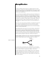
1
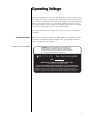
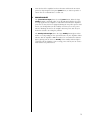
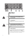
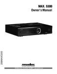
PR O C E E D
Five Channel Amplifier
WARNING: TO REDUCE THE RISK OF FIRE OR ELECTRIC SHOCK, DO
NOT EXPOSE THIS APPLIANCE TO RAIN OR MOISTURE.
CAUTION
RISK OF ELECTRIC SHOCK
DO NOT OPEN
CAUTION: TO REDUCE THE RISK OF ELECTRICAL SHOCK, DO
NOT REMOVE COVER. NO USER-SERVICEABLE PARTS INSIDE.
REFER SERVICING TO QUALIFIED PERSONNEL.
The lightning flash with arrowhead symbol, within an equilateral triangle, is intended to
alert the user to the presence of uninsulated “dangerous voltage” within the product’s enclosure that may be of sufficient magnitude to constitute a risk of electric shock to persons.
The exclamation point within an equilateral triangle is intended to alert the user to the
presence of important operating and maintenance (servicing) instructions in the literature
accompanying the appliance.
Marking by the “CE” symbol (shown left) indicates compliance of this device with the EMC
(Electromagnetic Compatibility) and LVD (Low Voltage Directive) standards of the
European Community.
The information contained in the manual is subject to change without notice. The most current version of this manual will
be posted on our web site at http://www.madrigal.com.
2
Important Saf ety Instructions
Please read all instructions and precautions carefully and completely before operating your Proceed power
amplifier.
1.
ALWAYS disconnect your entire system from the AC mains before connecting or disconnecting
any cables, or when cleaning any component.
2.
This product is equipped with a three-conductor AC mains power cord which includes an
earth ground connection. To prevent shock hazard, all three connections must ALWAYS be
used. If your electrical outlets will not accept this type of plug, an adapter may be purchased.
If an adapter is necessary, be sure it is an approved type and is used properly, supplying an
earth ground. If you are not sure of the integrity of your home electrical system, contact a licensed electrician for assistance.
3.
AC extension cords are not recommended for use with this product. If an extension cord must
be used, be sure it is an approved type and has sufficient current-carrying capacity to power
this product.
4.
NEVER use flammable or combustible chemicals for cleaning audio components.
5.
NEVER operate this product with any covers removed.
6.
NEVER wet the inside of this product with any liquid.
7.
NEVER pour or spill liquids directly onto this unit.
8.
NEVER block air flow through ventilation slots or heatsinks.
9.
NEVER bypass any fuse.
10. NEVER replace any fuse with a value or type other than those specified.
11. NEVER attempt to repair this product. If a problem occurs, contact your Proceed® retailer.
12. NEVER expose this product to extremely high or low temperatures.
13. NEVER operate this product in an explosive atmosphere.
14. ALWAYS keep electrical equipment out of the reach of children.
15. ALWAYS unplug sensitive electronic equipment during lightning storms.
3
From all of us at Madrigal Audio Laboratories, thank you for choosing this
Proceed power amplifier.
A great deal of effort went into the design and construction of this precision
device. Used properly, it will give you many years of enjoyment.
4
Table of Contents
Unpacking and Placement .................................................................
6
Unpacking .......................................................................................................... 6
Placement .......................................................................................................... 6
Ventilation ........................................................................................................... 6
Operating Voltage ..............................................................................
7
note the serial number ....................................................................................... 7
amplifier bottom-panel label ..................................................................... 7
A Quick Start ......................................................................................
Special Design Features .....................................................................
8
10
Multiple power supplies ................................................................................... 10
Low impedance power supply ....................................................................... 10
Balanced inputs ............................................................................................... 10
Robust output stage ......................................................................................... 10
Extensive protection ......................................................................................... 10
Home THX Audio System certification .............................................................. 11
Front Panel .........................................................................................
Rear Panel .........................................................................................
12
14
communication cable ............................................................................. 15
Remote turn-on tip polarity ...................................................................... 15
Bridged Operation .............................................................................
18
Bridging Explained ........................................................................................... 18
Balanced Bridging ........................................................................................... 18
Balanced Bridging Kit ............................................................................... 19
Single-Ended Bridging ...................................................................................... 20
Single-Ended Bridging Kit .......................................................................... 21
Biamplification ..................................................................................
23
Balanced Y-adapter ................................................................................. 23
Care & M aintenance ........................................................................
U.S. and Canadian Warranty ..............................................................
24
25
90-Day Limited Warranty .................................................................................. 25
Five Year Extended Warranty ........................................................................... 25
Obtaining Service .............................................................................
Specifications ....................................................................................
Dimensions .......................................................................................
Installation Notes ..............................................................................
26
27
28
29
5
Unpacking and Placement
Unpacking
Unpack your Proceed® Five Channel Amplifier and keep all packing m aterials
for future transport. Shipment of the amplifier without the original packing
material is not recommended, as it is heavy enough to make improvised packaging impractical. Locate and remove all accessory items from the cartons, and store
teh cartons for possible future use.
Carefully inspect the product for shipping damage. If you discover any, see your
Proceed dealer immediately.
Placement
Your Proceed amplifier may be placed either near the preamplifier/control center
or near the loudspeakers. It may be placed on a shelf or in a cabinet where it is
convenient to operate.
Note that adequate clearance for the AC cord and connecting
cables must be left behind your amplifier. We suggest leaving at
least three inches of free space behind your amplifier to allow all
cables sufficient room to bend without crimping or undue strain.
Ventilation
Be sure to allow 2 to 3 inches of clearance above your amplifier to allow heat
dissipation through air circulation. The vents on both the bottom and the top of
the amplifier must be kept free from any obstruction which would reduce the
flow of air through the unit. The best rule of thumb is this: if the top of your amplifier is too hot to touch when “idle,” it needs better ventilation. If so, consider
drilling holes in the supporting shelf under the amplifier to promote flow-through
ventilation, or use fans to increase air circulation.
Open equipment racks are generally best for power amplifiers, as they allow
ample ventilation. If your amplifier must be located inside a cabinet which restricts airflow, consider using some fans to increase ventilation.
Avoid placement on soft surfaces such as carpeting. If you prefer to have the amplifier on the floor near your loudspeakers, be sure to place it on a firm surface.
(A piece of tempered glass under the amplifier is aesthetically unobtrusive while
providing firm support and allowing the required ventilation.)
Mechanical drawings are included in this manual to facilitate special installations
and custom cabinet work (see “Dimensions” at the end of this manual).
PRECAUTION
6
For your protection, review “Important Safety Instructions”
before you install your amplifier.
Operating Voltage
The Proceed amplifier is factory-set for 100V, 120V, 220V, or 240V AC mains operation at either 50 or 60 Hz, according to the country for which the unit was manufactured. (230V in European Union countries, in compliance with CE regulations.)
Make sure that the label on the rear panel of the amplifier indicates the correct
AC operating voltage for your location. The operating voltage cannot be changed
by the user, and any attempt to do so will void the warranty.
If the voltage indicated does not match the service in your area, see your Proceed dealer.
note the serial number
amplifier bottom-panel label
While you are checking the voltage, it would probably be a good idea to make a
record of the serial number for your amplifier. This can be found on the label
found on the bottom of the amplifier.
WARNING: BEFORE ATTEMPTING TO OPERATE THIS
DEVICE, REFER TO OWNER'S MANUAL FOR PROPER
OPERATING INSTRUCTIONS AND SAFETY PRECAUTIONS.
HAZARDOUS VOLTAGE AVAILABLE INSIDE; DISCONNECT
AC ~ MAINS CABLE BEFORE OPENING UNIT.
PR O C E E D
R
five channel amplifier
S/N
MADRIGAL AUDIO LABORATORIES, INC.
designed and manufactured in USA
No User Serviceable Components Inside. For service, contact Madrigal Audio
Laboratories or an Authorized Dealer. Any modifications to this equipment will void all warranties.
Manufactured under license from Lucasfilm Ltd. Additionally licensed under the following
patents: U.S. number 5,043,970; 5,189,703; and 5,222,059. Foreign patents pending. Lucasfilm
THX Audio, Lucasfilm, and Home THX Cinema are registered trademarks of Lucasfilm Ltd.
7
A Quick Start
We recognize that many people are understandably eager to begin listening to
their new components, and that reading the manual is often done (if at all) at a
later time—perhaps while listening to music through the new product itself. We
strongly recommend that you read this manual thoroughly.
Fortunately, we can help you get some music up and running on your system
quickly, so that you may begin enjoying your new amplifier while reading more
about it. The goal here is simply to make some music as quickly as possible.
The following procedure assumes that the rest of your system is already connected (e.g., source components to preamplifier).
8
1
TURN DOWN THE VOLUME ON YOUR PREAMPLIFIER
Turning the volume on the preamp all the way down minimizes the opportunity for unpleasant surprises when first powering up your new amplifier.
It does not need to be turned off—merely turned down.
2
SELECT “XLR” OR “RCA” WITH THE “INPUT SELECT” SWITCHES
Each channel of the Proceed Five Channel Amplifier has both balanced
(XLR) and single-ended (RCA) inputs, with a small switch between the two
connectors to select between them. Using these switches, select the appropriate input for each channel, given your interconnecting cables and preamplifier/controller’s capabilities.
3
CONNECT YOUR PREAMP TO THE AMPLIFIER
Having selected the appropriate inputs in Step 2, now connect the outputs
of your preamplifier to the corresponding inputs on the power amplifier.
4
CONNECT YOUR SPEAKERS TO THE AMPLIFIER
Connect speaker wire from the amplifier to your loudspeakers. Be sure to
maintain consistency in polarity, e.g., the red post on the amplifier to the
red connector on the speaker, and likewise black to black. (Getting the
wires mixed up won’t damage anything, but the sound will be lacking in
bass and the imaging will be quite poor and unstable.)
5
CONNECT THE AC CORD TO THE AMPLIFIER AND TO YOUR AC OUTLET
The AC receptacle for the power cord is located on the right side of the
rear panel, as seen from the front.
6
TURN ON THE AMPLIFIER BY PRESSING POWER, THEN STANDBY
Press the latching power button on the front panel of the amplifier (small,
near the bottom) to connect the amplifier to the AC mains. The amplifier
will initially power up in standby mode. After five seconds (to let the power
supply charge up), pressing the large silver standby button will bring the
amplifier out of standby into its normal, fully operational mode.
7
SLOWLY RAISE THE VOLUME ON YOUR PREAMPLIFIER
Congratulations! You should now be able to enjoy your favorite music while
reading the rest of this manual. (Please, do read the rest of this manual. It
contains much valuable information about your new amplifier which we
could not possibly fit onto these two pages.)
9
Special Design Features
Congratulations on your purchase of a Proceed amplifier! While your new amplifier is straightforward in its use, it includes several design features which are responsible for its outstanding performance. A few of these are given below.
Multiple power supplies
Unlike other multichannel amplifiers, your new amplifier maintains outstanding
isolation and independence among its five channels. Three large toroidal transformers are used, with complete left/center/right channel separation maintained
throughout. Separate secondary windings for front vs. rear channels on the Left
and Right transformers feed separate rectifiers and separate banks of filter caps.
In short, after the transformer, each channel has its own, dedicated power supply.
This approach reduces crosstalk between audio channels for superior imaging
and reproduction of acoustic space. Any demands placed on one channel have
virtually no effect on the performance of the other channel(s).
Low impedance power supply
A critical factor in the ultimate performance of an amplifier is its “power supply
impedance,” which can be loosely thought of as the freedom with which the audio circuitry has access to the power it needs, when it needs it. The design of
your Proceed amplifier has addressed this important characteristic in a comprehensive fashion. For example, the power supply capacitors (which act as “reservoirs” of power for the amplifier circuitry) are mounted directly to the printed
circuit board rather than using point to point wiring. The layout of the circuitry
uses short, thick traces for high current paths. Internal current capability is further
enhanced with high purity copper bus bars. This attention to detail yields an optimal environment in which the amplifier may operate to its maximum potential.
Balanced inputs
Each channel of your amplifier is individually configurable to receive either balanced or single-ended inputs. This approach allows you to take full advantage of
the greater immunity from noise, RFI, and EMI which balanced transmission of
audio signals offers on any preamp-to-amplifier connection where it is supported.
At the same time, any or all channels of the amplifier may be configured for
single-ended inputs to maintain compatibility with the majority of preamplifiers
available today. The gain structure of the amplifier adjusts automatically when you
select different inputs to facilitate this “mix and match” approach.
Robust output stage
Each channel of your Proceed amplifier uses ten 150 watt power transistors.
These transistors are all individually tested and sorted, and are used in matched
sets to ensure that no one transistor bears a disproportionate part of the overall
load. The combination of an “overbuilt” design specification and extraordinary attention to detail in manufacturing improves performance, reliability, and longevity.
Extensive protection
Your Proceed amplifier will shut itself down if it senses either the presence of
either DC (direct current) or a short circuit at the output, or any unsafe operating
temperature. In any case, a power relay will cause the amplifier to be disconnected from the AC mains. In addition, the AC input to each transformer is fused
to protect against any possibility of component-level failure that could draw dangerous amounts of power. Finally, inrush limiting prevents premature aging of
10
power supply components during power-up, and switches off-line once the
power supply has been charged.
Home THX Audio
System certification
Lucasfilm, Ltd.® has established minimum standards for the performance of various components which may be used in their Home THX® Audio System. With
respect to power amplifiers, the standards address such things as:
• a low electrical noise floor to allow low-level information to be
fully appreciated;
• the absence of any mechanical noise (fan noise, transformer winding buzzes), for the same reason;
• adequate power to meet the demands of modern films (which can
be quite dynamic);
• flat frequency response for accurate reproduction of timbre;
• stability into relatively extreme loudspeaker loads, to ensure that
the amplifier will perform well with a wide range of loudspeakers.
As you can see from this list, there is nothing about the Home THX amplifier
specification that is particularly radical. It simply ensures a certain minimum standard of performance. In particular, there is nothing in the nature of the amplifier
specification which prevents anyone from going above and beyond the minimum
performance levels required by THX certification.
Your Proceed amplifier is certified for use in Home THX audio systems. Madrigal
engineers have created this powerful, versatile and extraordinarily musical power
amplifier, using the technology and design methodology for which they have become so well known. Equally suited to the rigors of film soundtracks and the finesse of high end music reproduction, the Proceed Five Channel Amplifier serves
both needs quite well. In today’s growing market for multipurpose systems, it
represents an extraordinary value.
11
2
five channel amplifier
standby
3
power
1
Front Panel
1
POWER BUTTON
Pressing this latching power button connects the amplifier to the AC mains,
charges the power supply (which takes about five seconds), and places it in
standby. Having a true standby function keeps the sensitive voltage gain
stages warmed up and sounding their best at all times. Power consumption
when in standby is less than 150 watts.
Note that if the amplifier has been disconnected from the AC mains power
by depressing the front panel power button or by unplugging it from the
AC outlet, it cannot respond to a remote turn-on command from a control
unit. If you wish the amplifier to turn on and off via the Proceed communications bus (or by a DC trigger), the amplifier needs to be in standby, with
this power button engaged.
2
STANDBY BUTTON
Assuming that the power is on and the unit is in standby (see 1, above),
pressing the standby button engages the output stage of the amplifier, taking it from standby to fully on. Pressing the standby button again will
toggle the amplifier back to standby. Power consumption when fully on and
at idle is less than 250 watts.
At your option, you may also toggle the amplifier between standby mode
and fully on by connecting a suitable 5-12V DC trigger such as can be provided by the Proceed PDSD or AVP to its remote trigger input.
Note that pressing the standby button has no effect until after the power
supply is fully charged.
12
Note also that if the amplifier has been disconnected from the AC mains
power by depressing the front panel power button, it cannot respond to a
remote turn-on command from a control unit.
3
INDICATOR LIGHTS
The power indicator light (above the small power button, below the large
standby button) is normally either on or off, indicating whether AC power
is being supplied to the amplifier. It will blink on and off if the amplifier’s
protection circuitry has been engaged (shutting the amp off to protect itself
and/or your loudspeakers). In the unlikely event that you see the power
indicator blinking, disconnect the amplifier from AC power and call your
dealer for assistance in solving the problem.
The standby indicator light (above the large standby button) glows either
amber or red, depending on the operational status of your amplifier. Amber
indicates that the amplifier is on and ready to be used. When the indicator
light is glowing red, the unit is in standby. If the standby indicator light is
completely off, the amplifier is not receiving power. Check your AC connections and the rear-panel AC fuse.
13
PR O C E E D
R
PUSH
PUSH
PUSH
PUSH
input select
PUSH
outputs
input select
1 2 3
right rear
input select
input select
right front
outputs
outputs
outputs
input select
communication
ports
outputs
trigger
inputs
~ac
mains
five channel amplifier by MADRIGAL AUDIO LABS made in u. s. a.
center
left rear
left front
4
5
6
7
Rear Panel
Caution!
Turn the volume on your controller/preamplifier all the way
down before attempting to connect anything to your Proceed
Five Channel Amplifier.
1
Warning!
Your Proceed amplifier has been safety-tested and is
designed for operation with a three-conductor power cord.
Do not defeat the “third pin” or earth ground of the AC power
cord.
2
14
AC MAINS RECEPTACLE
Connect the AC power cord (included in the accessory pack) to the IECstandard AC receptacle on the rear panel of the amplifier, then to the AC
mains outlet.
COMMUNICATION PORTS
These RJ-45 communications ports provide for sophisticated inter-component communications within the context of a Proceed system, allowing the
multichannel controller to toggle the amplifier between operate and
standby as needed, without forcing the user to turn the amplifier on separately. Since this communication link provides two-way communication, it is
more reliable and preferred over simpler DC trigger hookups (although we
support DC triggers as well, since their use is so widespread).
These two RJ-45 communications ports also support the PHAST™ intercomponent communications protocols, greatly simplifying the design and
installation of sophisticated home automation systems. They provide twoway communication with the home automation controller as to the
amplifier’s current status, ensuring reliable execution of sophisticated turnon and shutdown macros.
To use these ports, simply daisy chain the various Proceed products together. The modular cable needed for the connection may be purchased
from your Proceed dealer. It may also be easily and inexpensively made to
length using two modular connectors and the appropriate length (up to 100
feet/30 meters) of flat, eight conductor cable.
Modular cables and connectors are used throughout the world for both telecommunications and computers, and are widely available at low cost. The
connectors are crimped on to the ends of the cable such that pin 1 at one
end is connected to pin 1 at the other end. Such a “straight-through” connection is (counter-intuitively) made by introducing a 180° twist in the
cable between the two ends, as shown below.
communication cable
from Proceed PDSD or AVP
To Five Channel Amplifier
Locking tab
3
Remote turn-on
tip polarity
Locking tab
REMOTE TURN-ON (“TRIGGER’) JACKS
Two 1⁄8" “mini” jacks above the AC mains receptacle on the rear panel allows remote-controlled turn-on (that is, toggling between operate and
standby) of the Proceed amplifier. These remote “triggers” will be operated
by the presence of 5–12 volts DC, with tip polarity as shown below:
–
+
5-12 volts,
positive tip
polarity
The presence of a suitable DC voltage will cause the amplifier to be fully
on; the absence of such a voltage will cause it to enter standby. Your Proceed dealer can help you take advantage of these design features to maximize your system’s versatility.
Since these trigger inputs are wired in parallel, you can go into one and
out of the other to facilitate a “daisy-chain” of turn-on triggers (should you
have additional products that need to be controlled in this manner).
Special not e: if this method of control is used for the amplifier(s), the last
mini-jack in the chain must be terminated with a dummy 1⁄8" plug [that is,
an empty plug must be inserted into the final 1⁄8" (3.5 mm) jack]. Even if
only a single amplifier is controlled in this fashion, the “extra” mini-jack
must be terminated.
15
If you are not using these turn-on inputs, you may leave them both empty
of any plugs.
4
BALANCED AUDIO INPUTS
Accepts signals from preamplifiers with balanced outputs via high quality
XLR connectors.
The pin assignments of these XLR-type female input connectors are:
PUSH
2 1
3
Pin 1: Signal ground
Pin 2: Signal + (non-inverting)
Pin 3: Signal – (inverting)
Connector ground lug: chassis ground
These pin assignments are consistent with the standards adopted by the
Audio Engineering Society. Refer to the operating manual of your balancedoutput preamplifier to verify that the pin assignments of its output connectors correspond to your Proceed amplifier. If not, wire the cables so that the
appropriate output pin connects to the equivalent input pin.
If you are planning to use balanced connections between your preamplifier
and any particular channel of the amplifier, select the balanced input by
sliding the input select switch (see Item 5, below) toward the XLR input.
Then connect the balanced outputs of your preamplifier to the corresponding balanced inputs on the amplifier using high quality cables such as CZ
Gel-1.
5
INPUT SELECT SWITCH
This small switch is found between the balanced XLR input and the singleended RCA input on each channel of the amplifier. Use it to select which of
the two inputs you plan to use.
The input select switch disables the unselected input in order to avoid any
pickup of stray noise from what would otherwise be an open input. It also
causes the effective gain of that channel to be adjusted (either 23 dB balanced or 29 dB single-ended, to compensate for the 6 dB difference in signal level in these two connection standards). Should you use your amplifier
in a home theater system, this adjustment allows you to use any combination of balanced and single-ended connections without having to worry
about going outside the adjustment range of your surround decoder’s output calibration circuitry.
6
SINGLE-ENDED INPUTS
Accepts signals from preamp/controllers with single-ended outputs via high
quality RCA connectors.
If you are planning to use single-ended connections between your preamplifier and any particular channel of the amplifier, select the single-ended
input by sliding the input select switch (see Item 5) toward the RCA input.
Then connect the single-ended outputs of your preamplifier to the corresponding single-ended inputs on the amplifier, using high quality cable
such as CZ Gel-2.
16
7
Caution!
SPEAKER OUTPUTS & BINDING POSTS
The Proceed amplifier is equipped with gold-plated, high-current binding
posts for output termination to a loudspeaker system. To take full advantage
of the AMP’s sonic quality, we recommend using high-quality␣ speaker cable;
see your Proceed dealer.
NEVER connect the amplifier output terminals to any device
other than a loudspeaker.
NEVER short-circuit the amplifier’s output terminals.
There are two recommended methods for connecting speaker cables to the
amplifier. A high-quality␣ spade lug or hook lug, soldered to the cable (or
crimped with extremely high pressure), is best.
Spade lug
Hook lug
For each channel in turn, connect the left-channel – (negative or black) output post of the amplifier to the – (negative or black) input terminal of the
appropriate loudspeaker.
Then connect the + (positive or red) output post of the amplifier to the +
(positive or red) input terminal of the appropriate loudspeaker.
Repeat this procedure for all remaining channels.
17
Bridged Operation
Your Proceed amplifier has been designed to be extremely versatile. Should your
needs change or grow over time, you may wish to add additional power by one
of two means: Bridging, or Biamping. We will discuss bridged operation first.
Bridging Explained
Bridging refers to the act of reconfiguring the circuitry in two channels of your
amplifier to act as though it were a single, much larger amplifier. (Of course, this
reduces the number of available channels; you may need more amplifiers to
make up the difference.)
Bridging is accomplished by sending a normal signal to one channel and an inverted signal to the other. In this configuration, one channel will always be “pushing” when the other is “pulling.” By connecting the loudspeaker leads across the
left and right red output terminals, the amplifier can now deliver twice the normal voltage to the loudspeaker. Working together this way, the two amplifier channels can deliver about four times the power to a speaker that a single channel
could deliver on its own.
Bridged operation is particularly beneficial with low sensitivity, high-impedance
loudspeakers (8Ω or higher) that have a greater need for voltage than for current.
It is not recommended for low-impedance loudspeakers, as the speaker’s impedance is “split” by the two halves of the amplifier. Thus the bridged amplifier “sees”
a 2Ω load when connected to a 4Ω loudspeaker. Delivery of high power into
such a low impedance creates a great deal of heat that needs to be dissipated.
(Of course, your amplifier is protected against overheating, but having an amplifier shut itself down even temporarily can put a damper on the evening’s entertainment.)
Balanced Bridging
18
If your preamplifier has balanced outputs, you should use them. For this discussion, we will assume that you are using a Madrigal Balanced Bridging Kit for
each channel to be bridged. (Alternatively, you may have custom cables built using your preferred wire and connectors, being careful to follow the wiring diagram below.)
Balanced Bridging Kit
Balanced Bridging
Input Adapter
(pin configuration)
Male XLR Output (normal)
Pin 1: signal ground
Pin 2: signal + (non-inverting)
Pin 3: signal – (inverting)
1 2
3
2 1
3
(shield not connected)
Female XLR Input
Pin 1: signal ground
Pin 2: signal + (non-inverting)
Pin 3: signal – (inverting)
1 2
3
Male XLR Output (inverted)
Pin 1: not used (floated)
Pin 2: signal – (inverting)
Pin 3: signal + (non-inverting)
Bridging Output Adapter
(not drawn to scale)
The “normal” leg of the Madrigal Balanced Bridging Input Adapter will be marked
with a red stripe to indicate positive polarity, and the inverted leg will be marked
with a black stripe to indicate inverted polarity (corresponding to the red and
black terminals of your loudspeaker).
The Balanced Bridging Output Adapter is simply a heavy-gauge copper bar (silver- and gold-plated) used to strap two of the output ground terminals together.
This establishes a common reference for the amplifier and completes the circuit
that includes the loudspeakers.
Important!
Do not attempt to operate your amplifier in a bridged mode
without first strapping the black output terminals together.
Failure to establish a common ground reference between the
two channels can damage your amplifier by forcing
significant currents to flow where they do not belong!
To bridge your amplifier using a balanced input signal, follow these steps:
1
DISCONNECT YOUR AMPLIFIER FROM EVERYTHING
Start with your amplifier totally disconnected from inputs, outputs, and AC
power. It is always best to power down an amplifier before changing connections; here you are also changing its basic configuration, making this
step essential.
2
CONNECT THE BALANCED BRIDGING INPUT ADAPTER TO THE INPUTS
Connect the two male XLRs to two adjacent inputs on your amplifier, noting which XLR is marked red and which is black. The channel with the red,
normal input will later be connected to the red, positive terminal of your
loudspeaker. Don’t forget to choose the balanced input on each channel using the switch located between the XLR and the RCA connectors.
19
3
CONNECT THE BALANCED BRIDGING OUTPUT ADAPTER TO THE TWO
BLACK OUTPUT TERMINALS
Connect one end of the Balanced Bridging Output Adapter to a black output terminal on one of the two channels to be bridged together, and then
connect the other end of the Output Adapter to a black output terminal on
the other channel. Make sure these connections are snug and secure. (If
you need to use two channels of a different spacing—for example, two
center channel in different amplifiers—you can use a heavy gauge speaker
wire for this purpose.)
4
CONNECT YOUR LOUDSPEAKER WIRE ACROSS TWO RED OUTPUT TERMINALS, ONE TO EACH OF THE TWO CHANNELS BEING BRIDGED
Please read the following carefully:
Connect the positive/+/red binding post of your loudspeaker to the red
output terminal associated with the red (normal) side of the Input Adapter.
Connect the negative/–/black binding post of your loudspeaker to the red
output terminal on the other side of the amplifier, the one associated with
the black (inverted) side of the Input Adapter.
Following this connection convention preserves the polarity of the signal
sent to the loudspeaker. In practice, the most important thing is to be consistent throughout the system, as inconsistency will result in out-of-phase
loudspeakers. In turn, this results in unstable imaging and poor bass reproduction. (The effect is not dangerous, but neither is it desirable.)
Single-Ended Bridging
20
5
CONNECT ONE OUTPUT CHANNEL OF YOUR PREAMPLIFIER TO THE INPUT OF YOUR BRIDGED AMPLIFIER
The female XLR at the junction of the Balanced Bridging Input Adapter is
now the single input to this bridged pair of amplifier channels.
6
POWER UP YOUR AMPLIFIER
Plug the amplifier back into the AC mains; press the power button to turn
on the amplifier.
7
REPEAT THIS PROCESS WITH YOUR OTHER AMPLIFIER(S)
If your preamplifier has only single-ended (RCA) outputs, a few details of
bridged operation will differ from the discussion above, all pertaining to the connection of the preamp to the bridged amplifiers. For this discussion, we will assume that you are using a Madrigal Single-Ended Bridging Kit for each channel to
be bridged. (Alternatively, you may have custom cables built using your preferred
wire and connectors, being careful to follow the wiring diagram below.)
Single-Ended Bridging Kit
Single-Ended Bridging
Input Adapter
(pin configuration)
Male XLR Output (normal)
Pin 1: signal ground
Pin 2: signal + (non-inverting)
Pin 3: signal ground
1 2
3
Female RCA Input
Skirt: signal ground
Center: signal + (non-inverting)
1 2
3
Male XLR Output (inverted)
Pin 1: signal ground
Pin 2: signal ground
Pin 3: signal + (non-inverting)
Bridging Output Adapter
(not drawn to scale)
The “normal” leg of the Madrigal Single-Ended Bridging Input Adapter will be
marked with a red stripe to indicate positive polarity, and the inverted leg will be
marked with a black stripe to indicate inverted polarity (corresponding to the red
and black terminals of your loudspeaker).
The Balanced Bridging Output Adapter is simply a heavy-gauge copper bar (silver- and gold-plated) used to strap two of the output ground terminals together.
This establishes a common reference for the amplifier and completes the circuit
that includes the loudspeakers.
Important!
Do not attempt to operate your amplifier in a bridged mode
without first strapping the black output terminals together.
Failure to establish a common ground reference between the
two channels can damage your amplifier by forcing
significant currents to flow where they do not belong!
To bridge your Proceed amplifier using a single-ended (RCA) input signal, follow
these steps:
1
DISCONNECT YOUR AMPLIFIER FROM EVERYTHING
Start with your amplifier totally disconnected from inputs, outputs, and AC
power. It is always best to power down an amplifier before changing connections; here you are changing its basic configuration, making it essential.
2
CONNECT THE SINGLE-ENDED BRIDGING INPUT ADAPTER TO THE AMP’S
INPUTS
Connect the two male XLRs to two inputs of your amplifier, noting which
XLR is marked red and which is black. The channel with the red, normal
input will later be connected to the red, positive terminal of your loudspeaker.
21
3
CONNECT THE SINGLE-ENDED BRIDGING OUTPUT ADAPTER TO TWO
SIDE-BY-SIDE BLACK OUTPUT TERMINALS
Connect one end of the Balanced Bridging Output Adapter to a black output terminal on one side of the amplifier, and then connect the other end
to a black output terminal on the other side of the amplifier. (The two connections should be side-by-side rather than one above the other.) Make
sure these connection are snug and secure.
4
CONNECT YOUR LOUDSPEAKER WIRE ACROSS TWO SIDE-BY-SIDE, RED
OUTPUT TERMINALS
Please read the following carefully:
Connect the positive/+/red binding post of your loudspeaker to the red
output terminal associated with the red (normal) side of the Input Adapter.
Connect the negative/–/black binding post of your loudspeaker to the red
output terminal on the other side of the amplifier, the one associated with
the black (inverted) side of the Input Adapter.
Following this connection convention preserves the polarity of the signal
sent to the loudspeaker. In practice, the most important thing is to be consistent throughout the system, as inconsistency will result in out-of-phase
loudspeakers. In turn, this results in unstable imaging and poor bass reproduction. (The effect is not dangerous, but neither is it subtle.)
22
5
CONNECT ONE OUTPUT CHANNEL OF YOUR PREAMPLIFIER TO THE INPUT OF YOUR BRIDGED AMPLIFIER
The female RCA at the junction of the Single-Ended Bridging Input Adapter
is now the single input to this bridged amplifier.
6
REPEAT AS NEEDED FOR OTHER CHANNELS
7
POWER UP YOUR AMPLIFIER
Plug the amplifier back into the AC mains; engage the power button, followed a few seconds later by pressing standby to turn on the amplifier.
Biamplification
In contrast to bridged operation (wherein two amplifier channels are “fooled”
into behaving as a single, larger channel), biamplification makes use of two channels to drive different portions of a single loudspeaker. As with bridging, it offers a
modular way of increasing the overall performance of your system (if your loudspeakers support biamplification).
Since each channel of the amplifier is delivering current into its load only over a
limited range of frequencies (typically bass vs. mids and treble), several forms of
distortion may be reduced as compared to each channel handling the full range
of musical information. For this reason, many loudspeaker companies are designing their products to include multiple speaker inputs (since using multiple amplifiers improves the performance of their products as well). Another common use
of biamplification involves adding a subwoofer (along with an appropriate electronic crossover) to supplement and/or improve the deep bass performance of
your system.
Always refer to the specific directions provided by your loudspeaker manufacturer
prior to setting up a biamplified speaker system. Any instructions contained
herein cannot be substituted for those that are specific to the loudspeaker in
question. In general, however, biamping is done in one of two ways: active biamplification, or passive biamplification.
Active biamping refers to the presence of an “active” electronic crossover that divides the music into two (or sometimes more) bands of frequencies. These are
then forwarded to separate power amplifiers, and sent on directly to the appropriate drivers in the speakers. The most common application of this approach is
the use of a subwoofer crossover to separate the deep bass (below, say, 80 Hz)
from the rest of the program material. It is then amplified separately and sent to a
dedicated subwoofer designed to handle those extremely low frequencies.
Apart from adding a subwoofer, the next most common form of biamping (called
passive biamplification) involves merely using a conventional “Y-adapter” (either
balanced or single-ended) to provide a full range signal to two channels.
Male XLR Output
Pin 1: signal ground
Pin 2: signal + (non-inverting)
Pin 3: signal – (inverting)
Balanced Y-adapter
1 2
3
2 1
3
Female XLR Input
Pin 1: signal ground
Pin 2: signal + (non-inverting)
Pin 3: signal – (inverting)
1 2
3
Male XLR Output
Pin 1: signal ground
Pin 2: signal + (non-inverting)
Pin 3: signal – (inverting)
The outputs of these two channels are then connected to two sets of binding
posts on each loudspeaker. (See below.) The loudspeaker’s internal crossover continues to divide the frequencies appropriately among the various drivers.
To facilitate biamping, all Proceed power amplifiers have the same voltage gain
and input sensitivity. Because of this fact, you should not have to concern yourself with adjusting the relative volumes of the bass and treble sections of your
loudspeakers—if they sounded good with a single amplifier, they should sound
better when biamplified.
23
Care & Maintenance
To remove dust from the cabinet of your amplifier, use a feather duster or a lintfree soft cloth. To remove dirt and fingerprints, we recommend isopropyl alcohol
and a soft cloth. Dampen the cloth with alcohol first and then lightly clean the
surface of the amplifier with the cloth. Do not use excessive amounts of alcohol
that might drip off the cloth and into the amplifier.
Caution!
24
At no time should liquid cleaners be applied directly to the
amplifier, as direct application of liquids may result in
damage to electronic components within the unit.
U.S. and Canadian Warranty
90-Day Limited Warranty
This Proceed® product is warranted to be free from defects in material and workmanship under normal use for a period of ninety (90) days from the date of purchase. To extend the warranty of this Proceed product, return the warranty registration card along with a copy of the original receipt of purchase to Madrigal Audio
Laboratories, Inc., P. O. Box 781, Middletown, CT 06457.
Five Year Extended Warranty
The extended warranty for this Proceed product is five (5) years from the date of
purchase. During the warranty period, any Proceed component exhibiting defects
in materials and/or workmanship will be repaired or replaced, at our option,
without charge for either parts or labor, at our factory. The warranty will not apply
to any Proceed component that has been misused, abused or altered.
Any Proceed component not performing satisfactorily may be returned to the factory for evaluation. Return authorization must first be obtained by either calling
or writing the factory prior to shipping the component. The factory will pay for
return shipping charges only in the event that the component is found to be defective as above mentioned. There are other stipulations that may apply to shipping charges.
There is no other express warranty on this component. Neither this warranty nor
any other warranty, express or implied, including any implied warranties of merchantability or fitness, shall extend beyond the warranty period. No responsibility
is assumed for any incidental or consequential damages. Some states do not allow limitations on how long an implied warranty lasts and other states do not
allow the exclusion or limitation of incidental or consequential damages, so that
the above limitation or exclusion may not apply to you.
This warranty gives you specific legal rights, and you may also have other rights
which vary from state to state. This warranty is applicable in the United States and
Canada only. Outside of the U.S. and Canada, please contact your local, authorized Proceed distributor for warranty and service information.
25
Obtaining Service
We take␣ great pride in our dealers. Experience, dedication, and integrity make
these professionals ideally suited to assist with our customers’ service needs.
If your Proceed component must be serviced, please contact your dealer. Your
dealer will then decide whether the problem can be remedied locally, or whether
to contact Madrigal for further service information or parts, or to obtain a Return
Authorization. The Madrigal Technical Services Department works closely with
your dealer to solve your service needs expediently.
Important!
Return authorization must be obtained from Madrigal’s
Technical Services Department BEFORE a unit is shipped for
service.
It is extremely important that information about a problem be explicit and complete. A specific, comprehensive description of the problem helps your dealer and
the Madrigal Technical Services Department locate and repair the difficulty as
quickly as possible.
A copy of the original bill of sale will serve to verify warranty status. Please include it with the unit when it is brought in for warranty service.
Warning!
All returned units must be properly packaged (preferably in
their original packing material), and the proper return
authorization numbers must be marked on the outer carton
for identification. If the packaging to protect the unit is, in our
opinion or that of our dealer, inadequate to protect the unit,
we reserve the right to repackage it for return shipment at the
owner’s expense. Neither Madrigal nor your dealer can be
responsible for shipping damage due to improper (that is,
non-original) packaging.
Your dealer can order a new set of shipping materials for you if you need to ship
your component and no longer have the original materials. There will be a
charge for this service. We strongly recommend saving all packing materials in
case you need to ship your unit some day.
26
Specifications
The correlation between published specifications and performance is unreliable. A
list of numbers reveals virtually nothing. All technical measurements must be subject to qualitative as well as quantitative interpretation. Measurements of the Proceed amplifier yield excellent results by any standards. However, only those specifications that apply to its actual operation are included here. All specifications are
subject to change at any time, in order to improve the product.
■
■
■
■
■
■
■
■
■
■
■
■
Rated power output:
125 w/ch rms @ 8Ω, all channels driven,
20 Hz–20 kHz with no more than 0.1% THD
250 w/ch into 4Ω
Frequency response:
within 0.15 dB from 20 Hz to 20 kHz
Signal to Noise ratio (main outputs):
better than –80 dB (ref. 1 w)
Input impedance:
100kΩ (balanced)
10kΩ (single-ended)
Voltage gain:
23 dB (balanced)
29 dB (single-ended)
Input sensitivity:
2.24 V for full rated output (balanced)
1.12 V for full rated output (single-ended)
Power consumption:
less than 150 W in standby
less than 250 W when fully on and at idle
Mains voltage:
determined by the needs of country for which
the unit was manufactured; cannot be reset by dealer or user
Overall dimensions:
See “Dimensions”
Shipping weight:
119 lbs. (54 kg)
Connector Complement:
two binding posts per channel
one 3-pin XLR balanced input connector per channel
one RCA input connector per channel
two 1⁄8" mini-jacks for remote turn-on and loop-through
two RJ-45 modular connectors for PHAST™ communications
one IEC AC mains connector
Output impedance:
less than 0.05Ω, 20 Hz – 20 kHz
For more information, see your Proceed dealer, or contact:
Madrigal Audio Laboratories, Inc.
P.O. Box 781
2081 South Main Street (Route 17)
Middletown, Connecticut 06457 USA
Telephone (860) 346-0896
FAX
(860) 346-1540
Internet
http://www.madrigal.com/
Madrigal provides an owner-transferable, five year extended warranty on all
Proceed products within the U. S. and Canada ONLY. Warranty and service
policies outside the U. S. and Canada are set by the local, authorized
distributor and are applicable in the country of purchase ONLY. Madrigal
products are designed to operate at set voltages appropriate for the country
of sale and may be damaged if operated at the wrong voltage.
27
Dimensions
17.26"
43.84 cm
five channel amplifier
standby
6.53"
16.6 cm
power
17.61"
44.73 cm
0.695"
1.77 cm
15.47"
39.29 cm
19.55"
49.66 cm
1.40"
3.56 cm
16.87"
42.85 cm
PR O C E E D
R
PUSH
PUSH
PUSH
PUSH
input select
PUSH
outputs
input select
right rear
17.46"
44.35 cm
28
outputs
input select
input select
right front
outputs
outputs
input select
communication
ports
outputs
trigger
inputs
~ac
mains
five channel amplifier by MADRIGAL AUDIO LABS made in u. s. a.
center
left rear
left front
Rack Mounting
If you need or prefer to rack mount your amplifier, contact your Proceed dealer
about the optional rack mount kit. This purpose-designed assembly provides the
needed ventilation for the heatsink “chimneys” of the amplifier as well as the support required for this heavy component.
To use the rack mount kit, simply bolt the shelf securely to the rack, slide the amplifier into place, and then mount the provided trim ring around the faceplate of
the amplifier (which will protrude from the rack by approximately one inch or
2.5 cm). The drawing below will help you visualize the assembly.
The mounted amplifier and rack mount kit occupies 5 standard rack units of
height.
29
Madrigal Audio Laboratories, Inc.
2081 South Main Street, P.O. Box 781
Middletown, Connecticut 06457 USA
Telephone: (860) 346-0896
Fax: (860) 346-1540
http://www.madrigal.com/
PR O C E E D
R
is a registered trademark of Madrigal Audio Laboratories, Inc.
a Harman International company
630280-2
© 2/1998 Madrigal Audio Laboratories, Inc. All rights reserved.
Printed in U.S.A.