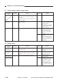
1
REVISION 0
APR. 1999
COPYRIGHT © 1999 CANON INC.
FY8-13G5-000
CANON NP6317 REV.0 APR. 1999 PRINTED IN JAPAN (IMPRIME AU JAPON)
IMPORTANT
THIS DOCUMENTATION IS PUBLISHED BY CANON INC., JAPAN, TO SERVE AS A SOURCE
OF REFERENCE FOR WORK IN THE FIELD.
SPECIFICATIONS AND OTHER INFORMATION CONTAINED HEREIN MAY VARY SLIGHTLY
FROM ACTUAL MACHINE VALUES OR THOSE FOUND IN ADVERTISING AND OTHER
PRINTED MATTER.
ANY QUESTIONS REGARDING INFORMATION CONTAINED HEREIN SHOULD BE DIRECTED
TO THE COPIER SERVICE DEPARTMENT OF THE SALES COMPANY.
THIS DOCUMENTATION IS INTENDED FOR ALL SALES AREAS, AND MAY CONTAIN INFORMATION NOT APPLICABLE TO CERTAIN AREAS.
COPYRIGHT © 1999 CANON INC.
Printed in Japan
Imprimé au Japon
Use of this manual should be strictly supervised to avoid disclosure of confidential
information.
Prepared by
OFFICE IMAGING PRODUCTS TECHNICAL SUPPORT DEPARTMENT 3
OFFICE IMAGING PRODUCTS TECHNICAL SUPPORT DIVISION
OFFICE IMAGING PRODUCTS QUALITY ASSURANCE CENTER
CANON INC.
5-1, Hakusan 7-chome, Toride-shi, Ibaraki 302-8501 Japan
COPYRIGHT © 1999 CANON INC.
CANON NP6317 REV.0 APR. 1999 PRINTED IN JAPAN (IMPRIME AU JAPON)
INTRODUCTION
This Service Manual contains basic data and figures for the Stapler Sorter-J1/K1/E3
needed to service the machine in the field.
General Description introduces the copier's features and specifications,
shows how to operate the copier, and explains how copies are made.
Chapter 2 Basic Operation provides outlines of the copier's various operational
workings.
Chapter 3 Exposure System discusses the principles of operation used for the copier's
lens drive unit and scanner drive unit. It also explains the timing at which
these drive units are operated, and shows how they may be disassembled/
assembled and adjusted.
Chapter 4 Image Formation System discusses the principles of how images are formed.
It also explains the timing at which the various units involved in image
formation are operated, and shows how they may be disassembled/
assembled and adjusted.
Chapter 5 Pick-Up/Feeding System explains the principles used from when copy paper
is picked up to when a copy is delivered in view of the functions of electrical
and mechanical units ahd in relation to their timing of operation. It also shows
how these units may be disassembled/assembled and adjusted.
Chapter 6 Fixing System explains the principles used to fuse toner images to tranfer
media in view of the functions of electrical and mechanical units and in
relation to their timing of operation. It also shows how these units may be
disassembled/assembled and adjusted.
Chapter 7 Externals/Auxiliary Mechanisms shows the copier's external parts, and
explains the principles used for the copier’s various control mechanisms in
view of the functions of electrical and mechanical units and in relation to their
timing of operation. It also shows how these units may be disassembled/
assembled and adjusted.
Chapter 8 Installtion introduces requirements for the site of installation, and shows how
the copier may be installed using step-by-step instructions.
Chapter 9 Maintenance and Servicing provides tables of periodically replaced parts and
consumables/durables and scheduled servicing charts.
Chapter 10 Troubleshooting provides tables of maintenance/inspection, standards/
adjustments, and problems identification (image fault/malfunction).
Chapter 1
Appendix contains diagrams showing electrical parts arrangement, tables of
signals, tables of special tools, tables of solvents/oils, and a general timing
chart.
The descriptions in this Service Manual are subject to change without notice for
product improvement or other purposes, and major changes will be communicated in the
from of Service Information bulletins.
All service persons are expected to have a good understanding of the contents of this
Service Manual and all relevant Service Information bulletins and be able to identify and
isolate faults in the machine.
COPYRIGHT © 1999 CANON INC.
CANON NP6317 REV.0 APR. 1999 PRINTED IN JAPAN (IMPRIME AU JAPON)
i
CONTENTS
CHAPTER 1 GENERAL DESCRIPTION
I.
II.
FEATURES ..................................1-1
SPECIFICATIONS .......................1-2
A. Type .......................................1-2
B. System ..................................1-2
C. Performance ..........................1-2
D. Others....................................1-3
III. NAMES OF PARTS ......................1-5
A. External View ........................1-5
B. Cross Section .......................1-6
IV. OPERATION ................................1-8
A. Control Panel.........................1-8
B. Daily Inspection to Be
Performed by the User ....... 1-10
V. IMAGE FORMATION ................ 1-11
A. Outline ................................ 1-11
CHAPTER 2 BASIC OPERATION
I.
BASIC OPERATION ....................2-1
A. Functions ...............................2-1
B. Outline of Electric Circuitry ...2-2
C. Inputs to DC Controller .........2-4
D.
E.
DC Controller Outputs ...........2-6
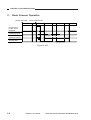
Basic Sequence of Operations
(Direct, Continuous Copying
(2 sheets)) .............................2-9
CHAPTER 3 EXPOSURE SYSTEM
I.
BASIC OPERATION ...................3-1
A. Changing the Reproduction
Ratio ......................................3-1
II. LENS DRIVE SYSTEM ................3-2
A. Outline ...................................3-2
B. Basic Lens Drive System
Operation (change of
reproduction ratio) .................3-3
III. SCANNER DRIVE SYSTEM .......3-4
A. Outline ...................................3-4
B. Relation Between Scanner
Sensor and Signals ...............3-5
C. Basic Scanner Operation ......3-6
COPYRIGHT © 1999 CANON INC.
D. Scanner Movement for
Two-Page Separation Mode
(copy count "2") .....................3-7
IV. No. 4/5 MIRROR DRIVE
SYSTEM ......................................3-8
V. DISASSEMBLY AND
ASSEMBLY ............................... 3-11
A. Lens Drive Assembly ......... 3-11
B. Scanner Drive Assembly .... 3-14
C. Exposure Assembly ........... 3-17
D. Blank Assembly .................. 3-19
E. No. 4/5 Mirror Mount........... 3-20
CANON NP6317 REV.0 APR. 1999 PRINTED IN JAPAN (IMPRIME AU JAPON)
iii
CHAPTER 4 IMAGE FORMATION SYSTEM
I.
PROCESSES ...............................4-1
A. Outline ...................................4-1
B. Basic Operation of Image
Formation System
(black developing assembly,
2 copies) ................................4-2
II. CONTROLLING THE SCANNING
LAMP ...........................................4-3
A. Outline ...................................4-3
B. Mechanism ............................4-4
III. PRIMARY/TRANSFER
CORONA CURRENT AND GRID
BIAS VOLTAGE CONTROL
SYSTEM ......................................4-5
A. Outline ...................................4-5
B. Switching Primary/Transfer
Corona Current ON/OFF .......4-5
C. Maintaining Primary/Transfer
Corona Current Constant ......4-6
D. Controlling Grid Bias
Voltage ..................................4-7
IV. CONTROLLING DEVELOPING
BIAS .............................................4-8
A. Outline ...................................4-8
B. Operation ..............................4-9
DOCUMENT DENSITY
MEASUREMENT SYSTEM ...... 4-11
A. Outline ................................ 4-11
B. Operation ........................... 4-11
C. Reading the Output of the AE
Sensor ................................ 4-12
D. Adjustment ......................... 4-13
VI. DEVELOPING ASSEMBLY/
DRUM CLAENER ..................... 4-14
A. Outlines .............................. 4-14
B. Remaining Toner Sensor .... 4-14
C. Torque Limiter..................... 4-15
VII. BLANKING ................................ 4-16
A. Outline ................................ 4-16
B. Movement of the Blank
Exposure Mechanism ........ 4-17
VIII. DISASSEMBLY AND
ASSEMBLY ............................... 4-19
A. Main Motor Assembly ......... 4-19
B. Corona System .................. 4-20
C. Primary/Transfer Corona
Assembly ............................ 4-22
D. Development System ......... 4-25
V.
CHAPTER 5 PICK-UP/FEEDING SYSTEM
I.
II.
PAPER PICK-UP ASSEMBLY AND
FEEDER.......................................5-1
A. Outline ...................................5-1
B. Pick-up and Feeder
Operation ..............................5-3
C. Identifying the Paper Size .....5-4
D. Pick-Up from the
Multifeeder .............................5-5
JAM DETECTION ........................5-7
A. Pick-up Assembly Delay
Jam ........................................5-8
B. Delivery Assembly Stationary
Jam ........................................5-9
C. Delivery Assembly Delay
Jam ..................................... 5-10
III. FEEDER SYSTEM.................... 5-11
A. Pick-up Assembly ............... 5-11
B. Feeder Assembly ............... 5-17
iv
COPYRIGHT © 1999 CANON INC.
CANON NP6317 REV.0 APR. 1999 PRINTED IN JAPAN (IMPRIME AU JAPON)
CHAPTER 6 FIXING SYSTEM
I.
BASIC OPERATIONS ..................6-1
A. Outline ...................................6-1
B. Operation of Fixing Assembly
Temperature Control
System ..................................6-3
III. DISASSEMBLY AND
ASSEMBLY ..................................6-4
A. Fixing Assembly ....................6-4
CHAPTER 7 EXTERNALS/AUXILIARY MECHANISMS
I.
II.
POWER SUPPLY .........................7-1
A. AC Driver DC Power
Supply ...................................7-1
DISASSEMBLY AND
ASSEMBLY ..................................7-3
A.
B.
C.
D.
E.
External Covers .....................7-4
Control Panel.........................7-7
Copyboard Cover ..................7-9
Fans .......................................7-9
PCBs .................................. 7-11
CHAPTER 8 INSTALLATION
I.
II.
LOCATION ...................................8-1
UNPACKING AND INSTALLING
THE COPIER ...............................8-2
A. Unpacking .............................8-2
B. Mounting the Drum ...............8-4
C. Checking the Operation ........8-5
D. Adding Toner .........................8-6
E. Checking the Image ..............8-7
F. Universal Cassette Code
Setting "123" .........................8-8
III. RELOCATING THE COPIER .......8-9
IV. INSTALLING THE CONTROL
CARD-V .................................... 8-10
CHAPTER 9 MAINTENANCE AND SERVICING
I.
II.
PERIODICALLY REPLACED
PARTS ..........................................9-1
DURABLE PARTS........................9-2
COPYRIGHT © 1999 CANON INC.
III. BASIC PROCEDURE FOR
PERIODIC SERVICING ...............9-3
IV. PERIODIC SERVICING
SCHEDULE .................................9-4
CANON NP6317 REV.0 APR. 1999 PRINTED IN JAPAN (IMPRIME AU JAPON)
v
CHAPTER 10 TROUBLESHOOTING
I.
MAINTENANCE AND
INSPECTION ............................ 10-1
A. Basic Image Adjustment
Procedure ........................... 10-1
B. Points to Check for Periodic
Maintenance ....................... 10-2
II. STANDARDS AND
ADJUSTMENT .......................... 10-3
A. Mechanical ......................... 10-3
B. Electrical ........................... 10-17
III. IMAGE
TROUBLESHOOTING ............ 10-21
A. Initial Check ...................... 10-21
B. Samples of Image
Faults ................................ 10-24
C. Troubleshooting of Image
Faults ................................ 10-25
IV. OPERATION
TROUBLESHOOTING ............ 10-37
A. Troubleshooting of
Malfunction ....................... 10-37
V.
TROUBLESHOOTING FEEDING
PROBLEMS ............................ 10-56
A. Paper Jams ...................... 10-56
VI. INCORRECT PAPER FEED
OPERATION ........................... 10-60
VII. FUNCTION AND ARRANGEMENT
OF THE ELECTRICAL
PARTS ..................................... 10-62
A. Sensors, Fuses and
Lamps............................... 10-62
B. Clutches, Solenoids, Fans,
Motors and Heaters ......... 10-63
C. Switches, Circuit Breakers,
Counters, Etc. .................. 10-64
D. PCBs ................................ 10-65
VIII. SERVICE MODE ..................... 10-66
A. Outline .............................. 10-66
B. Using the Service Mode ... 10-66
C. Guide to Service Mode .... 10-67
IX. SELF DIAGNOSIS .................. 10-69
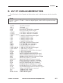
APPENDIX
A. GENERAL TIMING CHART ........ A-1
B. LIST OF SIGNALS/
ABBREVIATIONS ....................... A-3
vi
COPYRIGHT © 1999 CANON INC.
C. GENERAL CURCUIT
DIAGRAM ................................... A-5
D. SOLVENTS AND OILS LIST ....... A-7
CANON NP6317 REV.0 APR. 1999 PRINTED IN JAPAN (IMPRIME AU JAPON)
CHAPTER 1
GENERAL DESCRIPTION
I.
II.
FEATURES ..................................1-1
SPECIFICATIONS .......................1-2
A. Type .......................................1-2
B. System ..................................1-2
C. Performance ..........................1-2
D. Others....................................1-3
III. NAMES OF PARTS ......................1-5
A. External View ........................1-5
COPYRIGHT © 1999 CANON INC.
B. Cross Section .......................1-6
IV. OPERATION ................................1-8
A. Control Panel.........................1-8
B. Daily Inspection to Be
Performed by the User ....... 1-10
V. IMAGE FORMATION ................ 1-11
A. Outline ................................ 1-11
CANON NP6317 REV.0 APR. 1999 PRINTED IN JAPAN (IMPRIME AU JAPON)
CHAPTER 1 GENERAL DESCRIPTION
I. FEATURES
1.
Copies as large as A3 in size (DIRECT) may be made, and the copyboard is of a
fixed type.
• Although compact in design, the copier enables making copies as large as A3 in size in the
DIRECT mode.
• The copyboard is of a fixed type so that pages of a book may be copied with much ease.
2.
Zooming between 50% and 200%.
• Copies may be made in reproduction rations of between 50% and 200%, selectable in 1%
increments.
3.
Front loading for faster supply of paper.
• Paper is loaded from the front of the copier so that the cassette* may be replenished with
paper without wasting time. The design also saves space.
* Universal and its capacity is 500 sheets.
4.
Single-component fine particle toner for high resolution.
• Images are developed using the single component toner projection method. Further, the
copier uses toner of extremely fine particles for enhanced image quality.
5.
Multifeeder (stack bypass) pick-up.
• As many as 50 copies (80 g/m2) may be made continuously using the multifeeding mechanism.
6.
Low warm-up time
• The copier warms up in than 25 sec.
COPYRIGHT © 1999 CANON INC.
CANON NP6317 REV.0 APR. 1999 PRINTED IN JAPAN (IMPRIME AU JAPON)
1-1
CHAPTER 1 GENERAL DESCRIPTION
II. SPECIFICATIONS
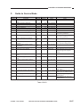
A.
Type
Body
Copyboard
Light sourse
Lens
Photosensitive medium
B.
Desktop
Fixed
Halogen lamp
Single lens + mirror movement
OPC
System
Indirect electrostatic method
Corona
Slit (moving light source)
Auto or manual
Dry
Exclusive cassette
Multifeeder
Corona
Curvature and Static eliminator
Blade
Heat roller (900W)
Reproduction
Charging
Exposure
Copy density adjustment
Development
Pick-up
Automatic
Manual
Transfer
Separation
Drum cleaning
Fixing
C.
Performance
Type of document
Document size
Wait time
First copy
Continuous copying
Cassette
Type of copy
Multifeed tray
paper
Sheet, Book, 3-D object (2 kg)
A3 max.
25 sec (approx.; at 20°C)
9.4 sec (A4, AE ON/OFF, 1:1)
99 copies
A3 (max.), A6 (min.;148x105 mm)
Plain paper (64 to 80 g/m2), Tracing paper, Colored paper
Plain paper (64 to 128 g/m2), Tracing paper*, Colored paper,
OHP film*, Label sheet
* Use of tracing paper may cause double feeding. If thin paper or OHP film, feed one sheet at a time.
1-2
COPYRIGHT © 1999 CANON INC.
CANON NP6317 REV.0 APR. 1999 PRINTED IN JAPAN (IMPRIME AU JAPON)
CHAPTER 1 GENERAL DESCRIPTION
Two-sided
copying
Overlay
copying
Cassette
Copy tray
Non-image
width (1st side)
Auto clear
Auto shutoff
Option
D.
Multifeed tray
Plain paper (64 to 128 g/m2), Colored paper
Multifeed tray
Plain paper (64 to 128 g/m2), Colored paper
Claw
Standard
Universal
Provided
60 mm deep (about 500 sheets of 80 g/m2 paper)
Yes
100 sheets (approx.; A4, 80 g/m2)
2.0 ±1.5 mm or less
2.5 ±1.5 mm or less
Provided (2 min, standard)
Yes
ADF-A1, MS-A1, Stapler Sorter D3, CC-V
Leading edge
Left/Right
Others
Power supply
Power
consumption
Noise
Ozone
Dimensions
Weight
Operating
environment
230V 50Hz
230V 50Hz
Maximum
Copying
Standby
Width
Depth
Height
Temperature
Humidity
Atmospheric
pressure
Others
COPYRIGHT © 1999 CANON INC.
Serial Numbers
UFW xxxxx
QFE xxxxx
1.5kW or less
(sound power level as prescribed by ISO)
55 dB or less
40 dB or less
0.05ppm or less (UL standards)
0.05 ppm or less (UL standards)
610 mm
617 mm
416 mm
50 kg or less
15.0° to 30°C
5% to 80%
0.6m to 1
Keep copy paper wrapped to protect against moisture.
CANON NP6317 REV.0 APR. 1999 PRINTED IN JAPAN (IMPRIME AU JAPON)
1-3
CHAPTER 1 GENERAL DESCRIPTION
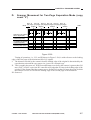
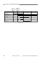
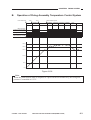
Reproduction mode
DIRECT
REDUCE
ENLARGE
1-4
I
II
I
II
Paper size
A3 (297x420mm)
A4 (210x297mm)
B4 (257x365mm)
B5 (182x257mm)
A5R (210x149mm)
50%
A3 → A4
A4 → A3
200%
COPYRIGHT © 1999 CANON INC.
Cassette
A3
A4
B4
B5
A5R
Copies/min
9
17
10
17
16
A4R
A3
10
9
CANON NP6317 REV.0 APR. 1999 PRINTED IN JAPAN (IMPRIME AU JAPON)
CHAPTER 1 GENERAL DESCRIPTION
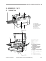
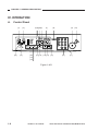
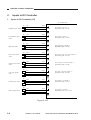
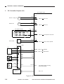
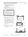
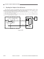
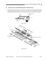
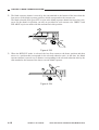
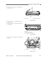
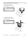
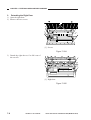
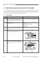
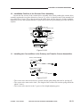
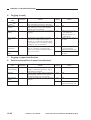
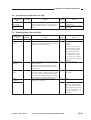
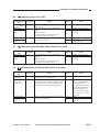
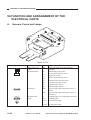
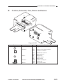
III. NAMES OF PARTS
A.
External View
[1]
[2]
[6]
[3]
[5]
[1]
[2]
[3]
[4]
[5]
[6]
[4]
Copy tray
Copyboard cover
Control panel
Cassette
Front cover
Delivery cover
Figure 1-301
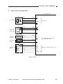
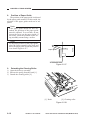
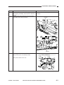
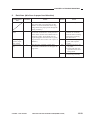
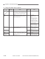
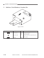
[2] [3]
[4]
[1]
[1]
[2]
[3]
[4]
[5]
[6]
[5]
[12]
[11]
[10] [8]
[9]
[7]
[6]
Copyboard glass
Power indicator
Power switch
Right cover
Multifeeder tray
Developing assembly
release lever
[7] Developing assembly
[8] Transfer/separation
assembly
[9] Primary corona assembly
cleaner
[10] Feeder assembly release
lever
[11] Copy density knob
[12] Fixing assembly knob
Figure 1-302
COPYRIGHT © 1999 CANON INC.
CANON NP6317 REV.0 APR. 1999 PRINTED IN JAPAN (IMPRIME AU JAPON)
1-5
CHAPTER 1 GENERAL DESCRIPTION
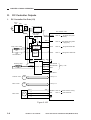
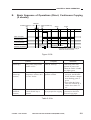
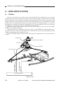
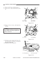
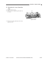
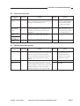
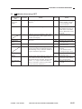
B.
Cross Section
[1]
[1]
[2]
[3]
[4]
[5]
[6]
[7]
[8]
[9]
[2]
[3]
[4]
[5]
[6]
[7]
[8]
[9]
[10]
[24]
[23]
[22]
[21]
[20]
[19]
[18]
[17]
[16]
[15]
[19]
[20]
[21]
[22]
[23]
[24]
Photosensitive drum
Cassette
Feeder assembly
Exhaust fan
Fixing assembly
Delivery roller
No. 3 mirror
No. 2 mirror
No. 1 mirror
Scanning lamp
Copyboard glass
Copyboard cover
Lens
Pre-exposure lamp
Primary corona
assembly
[10]
[11]
[12]
[13]
[14]
[15]
[16]
[17]
[18]
No. 6 mirror
No. 5 mirror
No. 4 mirror
Multifeeder tray
Developing assembly
Feeder roller 1
Pick-up roller
Registration roller
Transfer corona
assembly
[11]
[12]
[13]
[14]
Figure 1-303
1-6
COPYRIGHT © 1999 CANON INC.
CANON NP6317 REV.0 APR. 1999 PRINTED IN JAPAN (IMPRIME AU JAPON)
CHAPTER 1 GENERAL DESCRIPTION
Blank Page
COPYRIGHT © 1999 CANON INC.
CANON NP6317 REV.0 APR. 1999 PRINTED IN JAPAN (IMPRIME AU JAPON)
1-7
CHAPTER 1 GENERAL DESCRIPTION
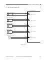
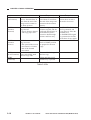
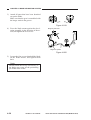
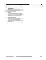
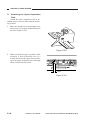
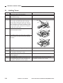
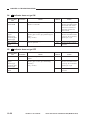
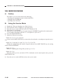
IV. OPERATION
A.
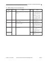
Control Panel
[1]
[22]
[2]
[21]
[20]
[19]
[18]
[3] [4][5] [6]
[7]
[17] [16]
[15] [14]
[8]
[13]
[9]
[12]
[10]
[11]
Figure 1-401
1-8
COPYRIGHT © 1999 CANON INC.
CANON NP6317 REV.0 APR. 1999 PRINTED IN JAPAN (IMPRIME AU JAPON)
CHAPTER 1 GENERAL DESCRIPTION
No.
Name
[1] Sort/Group key
[2]
[3]
[4]
[5]
Two-Page Separation key
Paper Jam indicator
Control Card Check indicator
Paper Out indicator
[6] Toner Out indicator
[7] Copy quantity/Copy ratio display
[8]
[9]
[10]
[11]
[12]
[13]
[14]
Reset key
Start key
Stop key
Clear key
Number keys
Percent key
Zoom keys
[15] Autom. Zoom key
[16] Paper Select key
[17] Paper Supply/Jam Location indicator
[18] Enlarge key
[19]
[20]
[21]
[22]
1:1 (Direct) Copy key
Reduce key
AE (Automatic Exposure) key
Exposure lever
COPYRIGHT © 1999 CANON INC.
Description
Press to select or cancel the Sort or Group mode.
* To use the Sort or Group mode, your copier must be
equipped with the optional Sorter or Stapler Sorter.
Press to select or cancel the Two-Page Separation mode.
Flashes when a paper jam occurs.
Flashes when the Control Card is not fully inserted.
Flashes when there is no paper in the selected paper supply (paper cassette or stack bypass).
Flashes when toner needs to be added.
Displays the number of copies to be made, and the selected enlargement/reduction ratio.
Also, when the copier is not functioning properly, the Service Call message will appear here.
Press to return the copier to the Standard mode.
Press to begin copying.
Press to stop the copier before copying is complete.
Press to change the number of copies to be made to one.
Press to input the number of copies to be made.
Press to display the selected enlargement/reduction ratio.
Press to reduce or enlarge copy images by any ratio from
50% to 200%, selectable in 1% increments.
Press to select or cancel Automatic Zoom.
* To use Automatic Zoom, your copier must be equipped
with the optional Automatic Document Feeder (ADF).
When copying using the stack bypass or a universal cassette, you cannot use Automatic Zoom.
Press to select the paper supply (paper cassette or stack
bypass).
Lights to show the selected paper supply (paper cassette
or stack bypass).
If a paper jam occurs, flashes to show jam location.
* This indicator will also flash to inform the user of various errors.
Press to enlarge copy images using a fixed enlargement
ratio.
Press to make copies the same size as the original.
Press to reduce copy images using a fixed reduction ratio.
Press to select or cancel Automatic Exposure Control.
Use to manually adjust the lightness/darkness of copies.
CANON NP6317 REV.0 APR. 1999 PRINTED IN JAPAN (IMPRIME AU JAPON)
1-9
CHAPTER 1 GENERAL DESCRIPTION
B.
Daily Inspection to Be Performed by the User
Carefully instruct the user to be sure to clean the following parts of the copier once a week.
1.
Primary Corona Assembly
Slide in and out the wire cleaner to clean the corona wires.
2.
Copyboard Glass
Clean the copyboard glass with a moist cloth; then, wipe it dry.
3.
Copyboard Cover
Clean the copyboard cover with a mild detergent solution; then, wipe it dry.
4.
Transfer Corona Assembly
Remove the transfer corona assembly from the copier; then, slide the knob (wire cleaner) at the
bottom of the transfer corona assembly back and forth to clean the corona wires.
Further, clean the static eliminator using the cleaning brush (accessory).
1-10
COPYRIGHT © 1999 CANON INC.
CANON NP6317 REV.0 APR. 1999 PRINTED IN JAPAN (IMPRIME AU JAPON)
CHAPTER 1 GENERAL DESCRIPTION
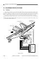
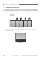
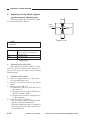
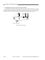
V. IMAGE FORMATION
A.
Outline
Copyboard glass
Scanning lamp
Lens
Developing
assembly
Primary corona assembly
Pre-exposure lamp
Cleaning roller
Drum cleaner
Picture to be changed
(1 register station only)
+
+
+
+
+
+
+
+
+
Upper fixing roller
+
+
+
Transfer corona assembly
+
+
Static charge
eliminator
+
Upper fixing roller
Figure 1-501
This copier consists of the units shown in Figure 1-501.
The image forming process is divided into the eight steps shown below.
Step 1: Pre-exposure
Step 2: Primary corona (negative DC)
Step 3: Image exposure
Step 4: Developing (positive plus AC)
Step 5: Transfer (negative DC)
Step 6: Separation
Step 7: Fixing
Step 8: Drum cleaning
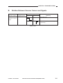
Electrostatic latent image formation block
2. Primary corona
3. Image exposure
1. Pre-exposure
4. Developing
8. Drum cleaning
5. Transfer
Copy delivery
6. Separation
7. Fixing
Multifeeder
Registration
Cassette
Flow of copy paper
Direction of rotation of drum
Figure 1-502
COPYRIGHT © 1999 CANON INC.
CANON NP6317 REV.0 APR. 1999 PRINTED IN JAPAN (IMPRIME AU JAPON)
1-11
CHAPTER 2
BASIC OPERATION
In outline diagrams,
represents mechanical drive paths, and
indicates
electrical signal paths.
Signals in digital circuits are identified as ‘1’ for High and ‘0’ for Low. The voltage of
signals, however, depends on the circuit.
Nearly all operations of the product are controlled by a microprocessor; the
internal workings of the processor are not relevant to the serviceman’s work and,
therefore, are left out of the discussions. By the same token, no repairs are
prescribed for the PCBs at the user’s premises; for this reason, PCBs are discussed
by means of block diagrams rather than circuit diagrams.
For the purpose of explanation, discussions are divided into the following: from
sensors to DC controller PCB input ports; from DC controller output ports to loads;
and minor control circuits and functions.
I.
BASIC OPERATION ....................2-1
A. Functions ...............................2-1
B. Outline of Electric Circuitry ...2-2
C. Inputs to DC Controller .........2-4
COPYRIGHT © 1999 CANON INC.
D.
E.
DC Controller Outputs ...........2-6
Basic Sequence of Operations
(Direct, Continuous Copying
(2 sheets)) .............................2-9
CANON NP6317 REV.0 APR. 1999 PRINTED IN JAPAN (IMPRIME AU JAPON)
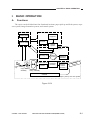
CHAPTER 2 BASIC OPERATION
I. BASIC OPERATION
A.
Functions
The copier can be divided into four functional sections: paper pick-up and feed system, exposure system, image formation system, and control system.
Control system
Exposure system
Control panel
Copybord
Scanner
Control circuit
Optical
system
Image tormation
system
Pnimary corona
Cleaning unit
Paper delivery
tray
Copy delivery
Fixing assembly
assembly
Feeder
Photosensitive drum
Transfer and
separation
assembly
Developing
assembly
Pick-up
control
assembly
er
ifeed
Mult mbly
asse
Cassette
Paper pick-up and feed system
Figure 2-101
COPYRIGHT © 1999 CANON INC.
CANON NP6317 REV.0 APR. 1999 PRINTED IN JAPAN (IMPRIME AU JAPON)
2-1
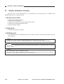
CHAPTER 2 BASIC OPERATION
B.
Outline of Electric Circuitry
The NP-6317's main mechanisms are controlled by the microprocessor, PROM, and
EEPROM on the DC controller PCB.
1. Microprocessor (Q300)
• controls the copying sequence
• controls the control panel
• controls the main motor/scanner motor/mirror motor
• controls the scanning lamp/fuser lamp
• reads the analog signals
2. PROM (Q301)
• contains the sequence program
3. EEPROM (Q317)
• stores data that can be modified in the service mode (replaces conventional variable resistors
and switches)
Note:
EEPROM is a type of ROM in which data may be erased or stored newly.
For this reason, the NP-6317's RAM and RAM are not backed up by a lithium battery.
Note:
The NP-6317 is equipped with an A/D converter and, therefore, its microprocessor can read
analog signals.
Note:
The main motor (M1) is a brushless motor.
The scanner motor (M2) and mirror motor (M3) are stepping motors which use the oscillation
frequency of the crystal oscillator on the DC controller.
2-2
COPYRIGHT © 1999 CANON INC.
CANON NP6317 REV.0 APR. 1999 PRINTED IN JAPAN (IMPRIME AU JAPON)
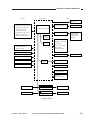
CHAPTER 2 BASIC OPERATION
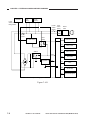
<Sensors>
<Control panel>
<Loads>
DC controller PCB
Main motor
AC driver/DC
power supply PCB
Scanner home position sensor
Fixing roller heater
Lens home position sendor
Cassette paper sensor
Microprocenssor (Q300)
Delivery paper sensor
Pre-registration paper sensor
HVT
Primary/Transfer
corona assembly
Multifeeder paper densor
Mirror home position sensor
Developing bias
PROM
(Q301)
EEPROM
(Q317)
GND bias
Registration roller clutch
Lens solenoid
Pick-up clutch solenoid
Cassette size sensor
Blank solenoid
Right door switch
Multifeeder solenoid
AE sensor
Lamp regulator
Scanning lamp
Black toner level sensor
Driver
(Q324)
Conntrol panel
Thermistors
Scanner motor
Mirror motor
Pre-exposure lamp
Exhaust fan
Scanner cooling fan
Microprocessor
Sensors, Switches
Sorter
Sorter controller PCB
Microprocessor
Sensors, Switches
ADF
ADF controller PCB
Figure 2-102
COPYRIGHT © 1999 CANON INC.
CANON NP6317 REV.0 APR. 1999 PRINTED IN JAPAN (IMPRIME AU JAPON)
2-3
CHAPTER 2 BASIC OPERATION
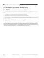
C.
1.
Inputs to DC Controller
Inputs to DC Controller (1/2)
DC controller PCB
Q1
Multifeeder paper sensor
Q2
Pre-registration paper
sensor
Q3
Right door sensor
Q4
Mirror home position
sensor
Q5
Scanner home position
sensor
Q6
Lens home position
sensor
Q7
Cassette paper sensor
Q8
Delivery paper sensor
5V
J24-1
J311-5
-2
-4
-3
-3
J23-1
J304-9
-2
-8
-3
-7
J27-1
J311-8
-2
-7
-3
-6
MFPD
when paper is over Q1, "1"
(light-blocking plate is at Q1)
5V
PRP
when paper is at Q2, "1"
(light-blocking plate is at Q2)
5V
RDC
when night door is closed, "1"
(light-blocking plate is at Q3)
5V
J801-1
J312-3
-2
-2
-3
-1
MHP
when mirror motor is at home position, "1"
(light-blocking plate is at Q4)
5V
J35-1
J312-6
-2
-5
-3
-4
J33-1
J312-9
-2
-8
-3
-7
J26-1
J303-7
-2
-6
-3
-5
J44-1
J314-5
-3
-3
-2
-4
SCHP
when scanner is at home position, "1"
(light-blocking plate is at Q5)
5V
LHP
when lens is at home position, "1"
(light-blocking plate is at Q6)
5V
CPEP
when paper is in cassette, "1"
(light-blocking plate is at Q7)
5V
DLP
when paper is at Q8, "0"
(light-blocking plate is not at Q8)
Figure 2-103
2-4
COPYRIGHT © 1999 CANON INC.
CANON NP6317 REV.0 APR. 1999 PRINTED IN JAPAN (IMPRIME AU JAPON)
CHAPTER 2 BASIC OPERATION
2.
Inputs to DC Controller (2/2)
DC controller PCB
AE
24V
J701-4
J312-13
-2
-11
-1
-10
-3
-12
J39-3
J303-3
-2
-2
-1
-1
J45-1
J317-1
-2
-2
-4
J317-4
-3
-3
J28-3
J313-2
-4
-3
-5
-4
-6
-5
-2
-1
24V
+
AE sensor
AE
See p. 3-25
AEGIN
TS1
5V
BTEP
Black toner
leveol sensor
Thermistor 2
(auxiliary)
TH2 (NTC2)
TH2
TH1(NTC1)
Thermistor 1
(main)
TH1
The voltage lowers as the fixing
heater temperature rises.
CST(SW3)
Cassette size
sensor
CSZ1
CSZ2
CSZ3
Reads the cassette size; see p. 3-32.
CSZ4
oscillation signal
Figure 2-104
COPYRIGHT © 1999 CANON INC.
CANON NP6317 REV.0 APR. 1999 PRINTED IN JAPAN (IMPRIME AU JAPON)
2-5
CHAPTER 2 BASIC OPERATION
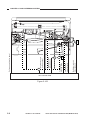
D.
1.
DC Controller Outputs
DC Controller Out Puts (1/3)
Noise
filter
DS1
SW1
Control panel PCB
J509-1
24V
J509-2
J503-1
DC controller PCB
Power supply
assembly
J316-11
24V
PWOFF
when "0"
AC power OFF (main
switch).
HTPT
when "0"
AC power OFF (power
supply unit).
HTCK
when "0"
fixing roller heater ON.
HTRD
when "1"
fixing roller heater ON.
K100
J318-3
Fixing heater
ON detection
circuit
Fixing roller heater
J4-1
LA1
Fixing
heater drive
circuit
-2
F1
Thermoswitch 1
Scanning lamp
LA2
-2
F2
-1
J201-1
J203
-1
J305
-6
-2
-4
-3
J202-3
-5
-2
-3
-4
-2
-5
-6
-1
Thermoswitch 2 -1 Lamp driver unit
24V
LAMP-CHECK
ZERO-CROSS
LIGHT
LAMP-SHIFT
Scanner motor
M2
See p. 3-9.
Mirror motor
M3
See p. 3-9.
Main motor
M1
J351-1
J301-1
-2
-2
-3
-3
-4
-4
See p. 3-20.
MMLOCK when "0"
MMD
when "1"
main motor is moving.
main motor ON.
+24V
Figure 2-105
2-6
COPYRIGHT © 1999 CANON INC.
CANON NP6317 REV.0 APR. 1999 PRINTED IN JAPAN (IMPRIME AU JAPON)
CHAPTER 2 BASIC OPERATION
2.
DC Controller Outputs (2/3)
DC controller PCB
Pick-up clutch solenoid
24V
J307-5
SL1
-6
Lens drive solenoid
PUSD
when "0", SL1 ON.
24V
J309-1
SL2
-2
Multifeeder solenoid
LNSD
when "0", SL2 ON.
24V
J311-9
SL3
-10
Blank solenoid
MFSD
when "0", SL3 ON.
24V
J307-7
SL4
-8
Registration roller clutch
BLSD
when "0", SL4 ON.
24V
J307-3
CL1
-4
RGCD
when "0", CL1 ON.
Figure 2-106
COPYRIGHT © 1999 CANON INC.
CANON NP6317 REV.0 APR. 1999 PRINTED IN JAPAN (IMPRIME AU JAPON)
2-7
CHAPTER 2 BASIC OPERATION
3.
DC Controller Outputs (3/3)
DC controller PCB
24V
J309-1
Scanner cooling fan
FM1
-2
FM1D
when "0"
FM1 ON
when "0"
FM2 ON
when "0"
Pre-exposure lamps ON
when "0"
Total counter operates
24V
J311-1
Exhaust fan
FM2
-3
Pre-exposure lamps
J731
-2
J307
-1
-1
-2
FM2D
24V
PEXP
24V
J314-2
CNT1
Total counter
-1
TCNTD
Control panel PCB
5V
CCV
J504-2
-4
J503-11
J316-1 CCNTC
When "0"
Operates.
-3
J503-10
-2 CCNNT
When "0"
Card sensed.
-1
Power indicator
PCB
5V
J505-1
J501
J502
J503
J315
J316
-2
Density volume
PCB
5V
J506-3
-2
-1
J501-1
J315-10
VR501
DNST
The voltage changes according
to the volume setting.
See p. 4-5.
H V T
Figure 2-107
2-8
COPYRIGHT © 1999 CANON INC.
CANON NP6317 REV.0 APR. 1999 PRINTED IN JAPAN (IMPRIME AU JAPON)
!"
CHAPTER 2 BASIC OPERATION
E.
Basic Sequence of Operations (Direct, Continuous Copying
(2 sheets))
WMUPR
POWER SWITCH
ON
90 C 110 C COPY START key
ON
WMUP
STBY
INTR
AER
SCRV
SCFW
SCRV
SCFW
LSTR
STBY
Main motor(M1)
Scanning lamp
Primary/transfer
corona assembly
Scanner movement
Scanner is set for
HOME position
Forward
Reverse
* Numbers in parentheses apply to
when the CT unit is used.
Figure 2-108
WMUP
(Warm-up)
Period
From switch on until the
fixing roller temperature
reaches 155°C.
Purpose
Allows time for fixing
roller to warm up.
WMUPR
(Warm-up
rotation)
Until the fixing roller
temperature reaches 90°C
to 110°C for the.
Keeps fixing roller temperature uniform.
INTR
(INITIAL
rotation)
About 2.2 sec after the
COPY START key is
pressed.
Stabilizes drum sensitivity to prepare for copying.
Remarks
Warm-up time varies
with fixing roller temperature at power ON.
When the COPY START
key lights green.
• After the WMUPR period ends, the READY/
WAIT indicator changes
from flashing green to
green.
• Even when the fixing
roller has warmed up, it
rotates for at least 4.2
sec.
A PAPER FEED signal is
generated to feed first
sheet of copy paper.
Table 2-101a
COPYRIGHT © 1999 CANON INC.
CANON NP6317 REV.0 APR. 1999 PRINTED IN JAPAN (IMPRIME AU JAPON)
2-9
CHAPTER 2 BASIC OPERATION
AER
(AE rotation)
SCFW
(Scanner
forward)
SCRV
(Scanner
reverse)
LSTR
(LAST rotation)
STBY
(Stand-by)
Period
From when the scanner
moves forward about 70
mm from the end of the
image until it returns to
its home position.
When the scanner is moving forward
• Travel distance changes
with copy paper size.
Purpose
Moves the scanner forward about 70 mm from
the end of the image and
measures the document
density.
The scanning lamp illuminates original, and the
reflected optical image is
transmitted to photosensitive drum through
mirrors and lens array.
While the scanner is moving in reverse.
• The speed of the reverse
movement is 2.5 times
that of the forward
movement.
Until the main motor
stops after SCRV until
the last copy ends.
The scanner is moved
back to HOME position
to prepare for the next
copy.
Remarks
In the non-AE mode the
scanner does not move
forward or in reverse.
• A REGISTRATION signal is generated, and
copy paper is fed to the
transfer area.
• A PAPER FEED signal
is generated to feed the
next sheet of copy paper.
Ensures full discharge of
the last copy.
Waits until the COPY
START key is pressed.
Table 2-101b
2-10
COPYRIGHT © 1999 CANON INC.
CANON NP6317 REV.0 APR. 1999 PRINTED IN JAPAN (IMPRIME AU JAPON)
CHAPTER 3
EXPOSURE SYSTEM
1. Disconnect the power cord for safety before disassembly or reassembly work.
2. Group the screws by type (length and diameter) and location.
3. The mounting screws are equipped with washers to protect against static
electricity; do not leave them behind when attaching the covers.
4. The mounting screw for the grounding wire is equipped with a washer to ensure
electrical continuity; make sure that the washer is attached to the screw when
removing/fitting it.
5. If possible, avoid operating the machine with any of its parts removed.
6. Unless otherwise noted, re-assembly is the reverse of disassembly.
I.
BASIC OPERATION ...................3-1
A. Changing the Reproduction
Ratio ......................................3-1
II. LENS DRIVE SYSTEM ................3-2
A. Outline ...................................3-2
B. Basic Lens Drive System
Operation (change of
reproduction ratio) .................3-3
III. SCANNER DRIVE SYSTEM .......3-4
A. Outline ...................................3-4
B. Relation Between Scanner
Sensor and Signals ...............3-5
C. Basic Scanner Operation ......3-6
COPYRIGHT © 1999 CANON INC.
D. Scanner Movement for
Two-Page Separation Mode
(copy count "2") .....................3-7
IV. No. 4/5 MIRROR DRIVE
SYSTEM ......................................3-8
V. DISASSEMBLY AND
ASSEMBLY ............................... 3-11
A. Lens Drive Assembly ......... 3-11
B. Scanner Drive Assembly .... 3-14
C. Exposure Assembly ........... 3-17
D. Blank Assembly .................. 3-19
E. No. 4/5 Mirror Mount........... 3-20
CANON NP6317 REV.0 APR. 1999 PRINTED IN JAPAN (IMPRIME AU JAPON)
CHAPTER 3 EXPOSURE SYSTEM
I.
BASIC OPERATION
A.
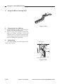
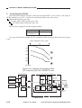
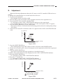
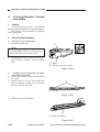
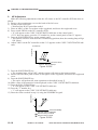
Changing the Reproduction Ratio
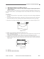
The reproduction ratio across the drum is varied by changing the position of the lens and the
position of No. 4 and No. 5 mirrors. It is moved by the lens drive system. The reproduction ratio
around the drum is varied by changing the speed of the scanner. Figure 3-101 shows how the
position of the lens and mirror is varied to change the reproduction ratio across the drum.
Lens
No. 4/5 mirror
100%
50%
200%
Figure 3-101
The scanner drive system changes the reproduction ratio around the drum by varying the speed
at which mirror 1 moves relative to the peripheral speed of the drum. (The scanner consists of
mirror 1 and the scanning lamp.)
The mirror speed is higher than the drum peripheral speed for REDUCTION and lower for
ENLARGEMENT.
Note:
For DIRECT copying, the speed of the mirror is the same as the peripheral speed of the
drum.
COPYRIGHT © 1999 CANON INC.
CANON NP6317 REV.0 APR. 1999 PRINTED IN JAPAN (IMPRIME AU JAPON)
3-1
CHAPTER 3 EXPOSURE SYSTEM
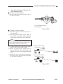
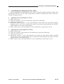
II. LENS DRIVE SYSTEM
A.
Outline
The lens is moved by the scanner motor (M2). Normally, the coupling gear is in its upper
position, and connects the scanner motor to the scanner drive capstan. To move the lens, the lens
solenoid (SL2) goes ON, causing the coupling gear to disengage from the scanner capstan gear and
engage with the lens capstan gear. The lens is a "floating element" type. In operation, the relative
position of lens elements (individual lenses) changes, and the focal length changes as a result, but
the changes are intended to optimize lens sharpness for each reproduction ratio, not to make the
lens function as a zoom lens. (The lens should not be dismantled.)
When the scanner motor rotates (CW), the lens will be moved to the left (for ENLARGEMENT) by the capstan and cable.
When the paper size is changed or when the copier is in the REDUCE mode, the blank exposure shutter moves in relation to the distance over which the lens travels, thereby blanking out the
width corresponding to the reproduction ratio.
The DC controller indicates 'E210' on the control panel in response to an error in the lens drive
system.
Couping gear
Scanner drive capstan
Solenoid "ON"
Scanner motor (M2)
SL2
Lens drive cable
Idler gear
Q4
LENS HOME POSITION
signal (LHP)
LENS SOLENOID
DRIVE command (LNSD)
Lens
ENLARGEMENT direction
DC contoroller PCB
Figure 3-201
3-2
COPYRIGHT © 1999 CANON INC.
CANON NP6317 REV.0 APR. 1999 PRINTED IN JAPAN (IMPRIME AU JAPON)
CHAPTER 3 EXPOSURE SYSTEM
B.
Basic Lens Drive System Operation (change of reproduction
ratio)
copy start
key ON
STAND BY
INITIAL ROTATION
AE ROTATION
SCAN FORWARD
Scanner home position
sensor (Q5)
Scanner motor (M2)
Scanner movement
Lens solenoid (SL2)
Lens movement
Lens home position
sensor (Q6)
Mirror home position
sensor (Q4)
Mirror movement
: Forward
: Reverse
Figure 3-202
When the paper size is changed or when the copier is in the ZOOM mode, the lens first returns
to the home position before moving to the position that corresponds to the cassette size and the
reproduction ratio.
This operation is executed also when the ZOOM mode is switched to the DIRECT mode.
COPYRIGHT © 1999 CANON INC.
CANON NP6317 REV.0 APR. 1999 PRINTED IN JAPAN (IMPRIME AU JAPON)
3-3
CHAPTER 3 EXPOSURE SYSTEM
III. SCANNER DRIVE SYSTEM
A.
Outline
The scanner is driven by the scanner motor (M2). The direction of rotation of the scanner motor
determines whether the scanner moves forward or backward. The forward speed of the scanner
motor is continuously variable to produce the required reproduction ratio. The reverse speed is
fixed regardless of the reproduction ratio (2.5 times the forward speed for DIRECT copying).
The distance that the scanner moves varies to suit the size of copy paper and the reproduction
ratio.
The control panel displays 'E202' in response to an error in the scanner motor (M2) or the
scanner home position sensor (Q5).
Scanner home
position sensor (Q5)
Mirror 2 mount
Mirror 1 mount
Lens gear
SL2
Scanner motor (M2)
A
COM-A
A
B
COM-B
B
J302-5
-4
-6
-2
-1
-3
Motor driver (Q324)
Solenoid
"OFF"
LENS
SOLENOID DRIVE
command (LNSL)
Signal generating
plate
DC controller
PCB
Connecting gear
Scanner home position signal (SCHP)
Forward
Figure 3-301
3-4
COPYRIGHT © 1999 CANON INC.
CANON NP6317 REV.0 APR. 1999 PRINTED IN JAPAN (IMPRIME AU JAPON)
CHAPTER 3 EXPOSURE SYSTEM
B.
Relation Between Scanner Sensor and Signals
Scanner sensor
Signal name
Scanner home
position sensor
(Q5)
SCHP
Scanner
Forward
Reverse
Meaning
• Grid bias ON
• After 0.1 sec, the scanner stops
advancing.
Table 3-301
COPYRIGHT © 1999 CANON INC.
CANON NP6317 REV.0 APR. 1999 PRINTED IN JAPAN (IMPRIME AU JAPON)
3-5
!!
CHAPTER 3 EXPOSURE SYSTEM
C.
Basic Scanner Operation
POWER switch ON
WMUP
COPY START key ON
STBY
INTR
AER
SCFW
SCRV
Forward
Reverse
SCFW
SCRV
LSTR
Scanner home
position sensor
(Q5)signal
Pre-registration paper
sensor (Q2) signal
Scanner movement
Scanning lamp
Figure 3-302
3-6
COPYRIGHT © 1999 CANON INC.
CANON NP6317 REV.0 APR. 1999 PRINTED IN JAPAN (IMPRIME AU JAPON)
CHAPTER 3 EXPOSURE SYSTEM
D.
Scanner Movement for Two-Page Separation Mode (copy
count "2")
Doc.L.E. Doc.L.E. Doc.L.E. Doc.L.E. Doc.L.E. Doc.L.E.
(1st page) (1st page) (1st page) (2st page) (1st page) (2st page)
INTR
SCRV1
SCRV1
SCFW1
SCFW1
Forward
Forward
SCRV2
SCFW2
STBY
SCRV2
SCFW2
LSTR
Scanner home position
sensor signal (Q5)
SCANNER FORWARD
command (SCFW)
SCANNER REVERSE
command (SCRV)
Scanning lamp (LA1)
Reverse
Forward
Reverse
Forward
Reverse
Reverse
Figure 3-303
Timing of operations, i.e., I, II, and III shown in Figure 3-304, is with reference to the leading
edge of the first page of the document (fall of Q3 signal).
I: The distance traveled by the scanner from the leading edge of the original is determined by the
reproduction ratio and the copy paper size, just as for a normal copy.
II: This is roughly the same as I. If the forward distance traveled by the scanner is greater than 210
mm (220V, or 240V copier) the DC controller will judge that 210 mm is the leading edge of the
original. If the distance that the scanner moves forward is less than 210 mm, the point at which
the scanner reverses in I will be the leading edge of the second page of the document.
III: Same as I.
COPYRIGHT © 1999 CANON INC.
CANON NP6317 REV.0 APR. 1999 PRINTED IN JAPAN (IMPRIME AU JAPON)
3-7
CHAPTER 3 EXPOSURE SYSTEM
IV. No. 4/5 MIRROR DRIVE SYSTEM
1.
Outline
The copier changes the reproduction ratio by varying the position of the No. 4/5 mirror and
moving the lens. Figure 3-401 shows the positions of the mirror and the lens according to different
reproduction ratios.
The mirror is driven by the mirror motor (M3), and its position is monitored by the mirror
home position sensor (Q4). The mirror is positioned with reference to the number of motor pulses
counted from the mirror home position.
When the power is turned on, the mirror motor (M3) continues to rotate clockwise until the
mirror home position sensor (Q4) turns on. Thereafter, it rotates counterclockwise for a specific
number of pulses to stop the No. 4/5 mirror at Direct position.
When a non-Direct ratio is selected during standby, both mirror and lens are driven accordingly.
Mirror
motor (M3)
Mirror
home position
sensor (Q4)
Enlargement /
Reduction
Direct
Figure 3-401
3-8
COPYRIGHT © 1999 CANON INC.
CANON NP6317 REV.0 APR. 1999 PRINTED IN JAPAN (IMPRIME AU JAPON)
CHAPTER 3 EXPOSURE SYSTEM
2.
Driving the Scanner Motor (M2) and the Mirror Motor (M3)
Figure 3-402 is a block diagram showing the drive circuit used for the scanner motor (M2) and
the mirror motor (M3). These motors are 4-phase stepping motors.
The pulse signals used to drive the motors (MIRRA, MIRRA*, MIRRB, MIRRB*) are generated by Q300 of the DC controller PCB; on the other hand, the motor select signal (MIRRCOM,
SCNCOM) is generated by Q300 and Q303.
The motor selected by the motor select signal is controlled for direction and speed by the pulse
signals from Q300.
DC controller PCB
24V
Q320
MIRRCOM
Q319
Q323 5V
MIRRA
J303
Q325
MIRRA*
MIRRA
5V
Q326
COM
Q325
MIRRA*
5V
Q327
MIRRB
MIRRB
Q325
MIRRB*
5V
Q328
MIRRB*
Q325
5V
5
Q329
4
2
1
Q330
Q370
TDA
Q324
Scanner motor
driver
J302
24V
Q365
SCNCOM
M3
3
5V
Q371
Q303
Mirror
motor
TDB
Q300
(CPU)
PMA
Q321
COM
PMA*
PMB
COM
PMB*
Scanner
motor
5
4
M2
6
2
1
3
Figure 3-402
COPYRIGHT © 1999 CANON INC.
CANON NP6317 REV.0 APR. 1999 PRINTED IN JAPAN (IMPRIME AU JAPON)
3-9
CHAPTER 3 EXPOSURE SYSTEM
100% to
70%
setting
70% to
50%
setting
50% to
200%
setting
Scanner motor (M2)
Lens HP sensor (Q6)
Mirror motor (M3)
Mirror HP sensor (Q4)
:motor foward
:motor reverce
Figure 3-403
3-10
COPYRIGHT © 1999 CANON INC.
CANON NP6317 REV.0 APR. 1999 PRINTED IN JAPAN (IMPRIME AU JAPON)
CHAPTER 3 EXPOSURE SYSTEM
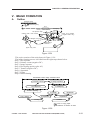
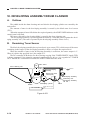
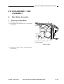
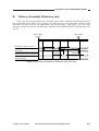
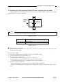
V. DISASSEMBLY AND ASSEMBLY
A.
Lens Drive Assembly
1.
Outline
The unit is adjusted at the factory with
high precision using special tools. Do not remove parts or loosen screws other than those
discussed.
Lens pully
Lens pully
fixing plate
[2]
4 turns
Mounting screws
[4]
[3]
Cable fixing
Pulley mount
Figure 3-501
COPYRIGHT © 1999 CANON INC.
CANON NP6317 REV.0 APR. 1999 PRINTED IN JAPAN (IMPRIME AU JAPON)
3-11
CHAPTER 3 EXPOSURE SYSTEM
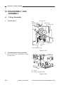
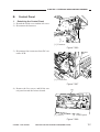
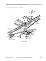
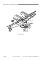
2. Detaching the Lens Cable
1) Detach the copyboard cover, copyboard
glass, lens cover, rear cover, and upper
rear cover.
2) Remove the three screws shown in Figure
3-502, and detach the upper frame.
[1]
[1] Screws
Figure 3-502
3) Mark the position of the pulley mount and
the cable mount using a scriber.
4) Remove the two screws that hold the pulley mount in place.
5) Detach the cable.
3-12
COPYRIGHT © 1999 CANON INC.
CANON NP6317 REV.0 APR. 1999 PRINTED IN JAPAN (IMPRIME AU JAPON)
CHAPTER 3 EXPOSURE SYSTEM
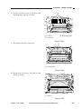
3. Routing the Lens Cable
1) Remove the two screws that hold the lens
pulley mount in place, and detach the lens
pulley; see Figure 3-501.
[2]
[1]
[3]
[1] Screws
[3] Pulley mount
[2] Pulley
Figure 3-503
2) Wind the lens cable around the lens pulley
as shown in Figure 3-504; then, fix it using two screws.
3) Shift the pulley mount to the position
marked with a scriber, and fix it in place
using two screws.
COPYRIGHT © 1999 CANON INC.
CANON NP6317 REV.0 APR. 1999 PRINTED IN JAPAN (IMPRIME AU JAPON)
3-13
CHAPTER 3 EXPOSURE SYSTEM
B.
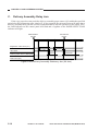
Scanner Drive Assembly
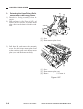
1. Detaching the Scanner Cable
1) Mark the position of the mount, and
loosen screws B (2 pcs.), which hold the
mount in place.
2) Loosen screw A (1 pcs.), and detach the
scanner cable.
2. Attaching the Scanner Cable
1) Route the scanner cable as shown in Figure 3-504.
2) Position the fixing plate where a mark has
been put using screw A.
3) Tighten screws B.
[6]
[2]
Pulley 1
[6]
Pulley 3
[5]
Top groove of the pulley
Lower groove of the pulley
Scanner pulley
[4]
[1]
[3]
Pulley 2
Mark the position
Screw A
Screws B
Figure 3-504 Scanner Drive Assembly
3-14
COPYRIGHT © 1999 CANON INC.
CANON NP6317 REV.0 APR. 1999 PRINTED IN JAPAN (IMPRIME AU JAPON)
CHAPTER 3 EXPOSURE SYSTEM
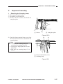
3.
Adjusting the Mirror Position (optical distance between No. 1 and
No. 2 mirrors)
Adjust the position of the mirror after attaching the scanner cable.
To adjust, relocate the fixing used for the
No. 1 mirror mount; loosen the two screws.
Note:
i. The cable tends to become slack as
more and more copies are made, requiring adjustment.
ii. If the horizontal reproduction ratio
becomes faulty because of inaccurate
optical distance between the No. 1
and No. 2 mirrors, the images on copies will become out of focus.
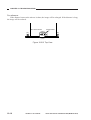
1) Draw a line 1 cm from both ends of copy
paper (A4 or A3) as shown in Figure 3505.
2) Make a copy of the sheet on which lines
have been drawn; call the copy obtained
this way "sheet A."
3) Place a blank sheet of paper on the
copyboard, and feed the sheet on which
lines were drawn in the manual mode; call
the delivered-sheet "sheet B."
• Sheet B will show contraction by heat.
4) Put the left lines on sheet A and sheet B
together, and adjust the position of the No.
1 mirror mount so that x and y in Figure 3406 are identical.
1cm
1cm
Lines
Figure 3-505
x
Sheet A
x=y correct
x>y move the No.1 mirror mount into the
direction of [a]
x<y move the No.1 mirror mount into the
direction of [b]
Sheet B
y
Figure 3-506
No.1mirror mount
Fixing screws
(front)
b
a
Mirror drive cable
(rear)
Figure 3-507
COPYRIGHT © 1999 CANON INC.
CANON NP6317 REV.0 APR. 1999 PRINTED IN JAPAN (IMPRIME AU JAPON)
3-15
CHAPTER 3 EXPOSURE SYSTEM
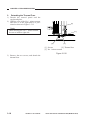
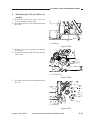
4.
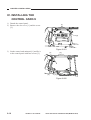
Using the Mirror Cleaning Tool
Figure 3-508
5. Cleaning the No. 6 Mirror
1) Detach the drum cartridge, developing assembly, and dustproofing glass.
2) Put the mirror cleaning tool against the
mirror as shown in Figure 3-509, and
clean the lens by sliding it back and forth.
Use the upper registration roller as a reference for sliding back and forth.
6.
Lubricating
Clean the scanner rail; then, apply lubricant evenly over it.
No. 6 mirror
Mirror cleaning tool
Figure 3-509
3-16
COPYRIGHT © 1999 CANON INC.
CANON NP6317 REV.0 APR. 1999 PRINTED IN JAPAN (IMPRIME AU JAPON)
CHAPTER 3 EXPOSURE SYSTEM
C.
Exposure Assembly
1. Detaching the Scanning Lamp
1) Disconnect the power plug.
2) Detach the copyboard glass.
3) Remove the two screws, and detach the
anti-glare plate.
[1]
[2]
[1] Screws
[2] Anti-glare plate
Figure 3-510
4) Push the lamp terminal plate (rear) into
the direction of the arrow, and detach the
scanning lamp.
[2]
[1]
Note:
i. Wait until the scanning lamp has
cooled before starting the work.
ii. Do not leave fingerprints on the scanning lamp.
iii. Dry wipe the scanning lamp if it is
soiled.
[1] Lamp terminal plate (rear)
[2] Scanning lamp
Figure 3-511
COPYRIGHT © 1999 CANON INC.
CANON NP6317 REV.0 APR. 1999 PRINTED IN JAPAN (IMPRIME AU JAPON)
3-17
CHAPTER 3 EXPOSURE SYSTEM
2. Detaching the Thermal Fuse
1) Detach the control panel and the
copyboard glass.
2) Hold the rear of the No. 1 mirror mount,
and move it to the right until it is positioned as shown in Figure 3-512.
[3]
Note:
When moving the No. 1 mirror mount,
be sure to hold its right side.
[1]
[1]
[2]
[1] Screws
[2] Thermal fuse
[3] No. 1 mirror mount
Figure 3-512
3) Remove the two screws, and detach the
thermal fuse.
3-18
COPYRIGHT © 1999 CANON INC.
CANON NP6317 REV.0 APR. 1999 PRINTED IN JAPAN (IMPRIME AU JAPON)
CHAPTER 3 EXPOSURE SYSTEM
D.
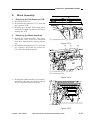
Blank Assembly
[1]
1. Detaching the Pre-Exposure PCB
1) Detach the rear cover.
2) Disconnect the connector (J731) from the
pre-exposure PCB.
3) Hold the pre-exposure PCB using pliers,
and pull it straight out taking care not to
damage the PCB.
2. Detaching the Blank Assembly
1) Detach the copyboard glass, lens cover,
lens motor cover, rear cover, and drum
unit; then, detach the developing assembly.
2) Disconnect the connector (J731) from the
pre-exposure PCB and the connector
(J30) from the blank solenoid.
[2]
[1] Lens motor cover [2] Screw
Figure 3-513
[3]
[1]
[2]
[1] Connector (J731) [2] HVT
[3] Connector (J30)
Figure 3-514
3) Holding the blank assembly on its bottom,
and remove the four screws; then, pull out
the pre-exposure lamp to the front.
[1]
[1]
[1] Screws
Figure 3-515
COPYRIGHT © 1999 CANON INC.
CANON NP6317 REV.0 APR. 1999 PRINTED IN JAPAN (IMPRIME AU JAPON)
3-19
CHAPTER 3 EXPOSURE SYSTEM
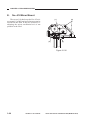
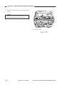
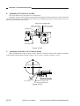
E.
No. 4/5 Mirror Mount
The screws [A] that keeps the No. 4/5 mirror mount [1] to the lens base plate must not be
loosened in the field. If they are loosened, readjusting the mirror mechanical axis is not
possible in the filed.
[A]
[1]
[A]
[A]
Figure 3-516
3-20
COPYRIGHT © 1999 CANON INC.
CANON NP6317 REV.0 APR. 1999 PRINTED IN JAPAN (IMPRIME AU JAPON)
CHAPTER 4
IMAGE FORMATION SYSTEM
I.
PROCESSES ...............................4-1
A. Outline ...................................4-1
B. Basic Operation of Image
Formation System
(black developing assembly,
2 copies) ................................4-2
II. CONTROLLING THE SCANNING
LAMP ..........................................4-3
A. Outline ...................................4-3
B. Mechanism ............................4-4
III. PRIMARY/TRANSFER
CORONA CURRENT AND GRID
BIAS VOLTAGE CONTROL
SYSTEM ......................................4-5
A. Outline ...................................4-5
B. Switching Primary/Transfer
Corona Current ON/OFF .......4-5
C. Maintaining Primary/Transfer
Corona Current Constant ......4-6
D. Controlling Grid Bias
Voltage ..................................4-7
IV. CONTROLLING DEVELOPING
BIAS .............................................4-8
A. Outline ...................................4-8
COPYRIGHT © 1999 CANON INC.
B. Operation ..............................4-9
V. DOCUMENT DENSITY
MEASUREMENT SYSTEM ...... 4-11
A. Outline ................................ 4-11
B. Operation ........................... 4-11
C. Reading the Output of the AE
Sensor ................................ 4-12
D. Adjustment ......................... 4-13
VI. DEVELOPING ASSEMBLY/
DRUM CLAENER ..................... 4-14
A. Outlines .............................. 4-14
B. Remaining Toner Sensor .... 4-14
C. Torque Limiter..................... 4-15
VII. BLANKING ................................ 4-16
A. Outline ................................ 4-16
B. Movement of the Blank
Exposure Mechanism ........ 4-17
VIII. DISASSEMBLY AND
ASSEMBLY ............................... 4-19
A. Main Motor Assembly ......... 4-19
B. Corona System .................. 4-20
C. Primary/Transfer Corona
Assembly ............................ 4-22
D. Development System ......... 4-25
CANON NP6317 REV.0 APR. 1999 PRINTED IN JAPAN (IMPRIME AU JAPON)
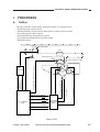
CHAPTER 4 IMAGE FORMATION SYSTEM
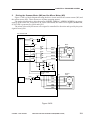
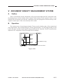
I. PROCESSES
A.
Outline
The basic structure of the image formation system is as shown below.
• Scanning lamp control system
• Primary/transfer corona current and grid bias voltage control system
• Developing bias control system
• Document density measurement system
• Developing assembly/drum cleaning system
• Blanking system
Scanning lamp
Lens
Pre-exposure lamp
AE sensor
Photosensitive
Developing bias
GRID ON signal (GRDON)
Transfer corona assembly
high voltage
drum
Static charge eliminator bias
(LIC)
LIGHT INTENSITY
CONTROL command
LAMP ON command
(LAON)
AE
Lamp
driver unit
PRE-EXPOSURE LAMP DRIVE command
(PEXP)
Blank exposure shutter
HVTON command (HVTON)
DC controller
PCB
AC BIAS ON command
(ACBON)
DC BIAS control command
(DCBC)
High-voltage
transformer
(HVT)
GRID BIAS control signal (GRBC)
Figure 4-101
COPYRIGHT © 1999 CANON INC.
CANON NP6317 REV.0 APR. 1999 PRINTED IN JAPAN (IMPRIME AU JAPON)
4-1
CHAPTER 4 IMAGE FORMATION SYSTEM
B.
Basic Operation of Image Formation System (black developing assembly, 2 copies)
COPY START key
ON
WMUPR
WMUP
STBY
INTR
AER
SCFW
SCRV
SCFW
SCRV LSTR
STBY
Main motor(M1)/
pre-exposure lamp
Forward
Scanner movement
Backward
Scanner home position
sensor (Q5) signal
Scanning lamp(LA1)
Primary/transfer
corona assembly
Grid bias ON/OFF
Developing bias DC
component
Developing bias AC
component
LIGHT INTENSITY
CONTROL command
Figure 4-102
4-2
COPYRIGHT © 1999 CANON INC.
CANON NP6317 REV.0 APR. 1999 PRINTED IN JAPAN (IMPRIME AU JAPON)
CHAPTER 4 IMAGE FORMATION SYSTEM
II. CONTROLLING THE SCANNING LAMP
A.
Outline
The scanning lamp (LA1) is controlled by the DC controller PCB.
Specifically, the DC controller
• turns the scanning lamp ON and OFF.
• controls the intensity of the scanning lamp.
COPYRIGHT © 1999 CANON INC.
CANON NP6317 REV.0 APR. 1999 PRINTED IN JAPAN (IMPRIME AU JAPON)
4-3
CHAPTER 4 IMAGE FORMATION SYSTEM
B.
Mechanism
1.
Turning the Scanning Lamp ON and OFF
The microprocessor (Q300) on the DC controller PCB controls the lamp regulator. The scanning lamp goes ON when the scanning LAMP ON command (LOAN) is '1', and it goes OFF when
the signal is '0'.
2.
Controlling the Intensity of the Scanning Lamp
The intensity of the scanning lamp is controlled by the lamp shift signal.
The intensity of the scanning lamp is changed.
When the reproduction ratio is different than 100% changing the T-on time of the lamp shift
signal. The T-on time of the lamp shift signals is fixed to 5ms at 100%. During AE exposure,
however, the voltage (135 V) applied to the scanning lamp remains the same.
The adjusts the copy density using its development bias; see p. 10-18.
3.
Error Protection
The condition of the scanning lamp is monitored using the lamp check signal.
If the lamp check signal is received by the DC controller even when the lamp is off, the error
detection circuit generates the AC SHUTOFF signal to force the relay (K100) on the AC driver/DC
power supply PCB to go OFF, thereby cutting AC power supply (p. 3-39). In this case, E220 error
is displayed.
4.
Zero-Cross Signal
The board generates the zero cross signal that the DC controller uses to control the fixing
heater temperature. E261 is indicated on the control panel if an zero cross error is identified.
Transistor
(Q320)
Microprocessor (Q300)
Error
detection
circuit
Power supply assembly
DC controller PCB
J306
-4
MEAT
Relay
K100
J201
-1
-2
J305 J203
-4
-3
LAMP
CHECK
ZERO
CROSS
J305 J203
-2
-5
J305 J203
-1
-6
LAMP
SHIFT
J305 J203
-4
-3
LAMP-ON
J202-1
Lamp ON
detection
circuit
FU2
Scanning lamp
(LA1)
Intensity
switching
circuit
Phase
control
switching
circuit
Triac-triggering circuit
J202-3
Lamp driver unit
Short connector
Figure 4-201
4-4
COPYRIGHT © 1999 CANON INC.
CANON NP6317 REV.0 APR. 1999 PRINTED IN JAPAN (IMPRIME AU JAPON)
CHAPTER 4 IMAGE FORMATION SYSTEM
III. PRIMARY/TRANSFER CORONA CURRENT AND
GRID BIAS VOLTAGE CONTROL SYSTEM
A.
Outline
The circuit shown in Figure 4-102 controls the primary/transfer coronal current and the bias
voltage of the grid of the primary corona. Main functions are as follows:
1. Switching primary/transfer corona current ON/OFF
2. Maintaining primary/transfer corona current constant
3. Switching primary corona grid bias voltage
4. Switching primary corona grid bias ON/OFF
In order to eliminate the effect of changes in atmospheric conditions on the effectiveness of the
corona discharge, the current to the primary corona wire is maintained constant.
The primary corona and transfer corona currents are switched ON and OFF by the HVT ON
command (HVTON).
The grid bias voltage is switched by the GRID ON signal (GRDON).
B.
Switching Primary/Transfer Corona Current ON/OFF
a. When HVTON=1,
Differential amplifier goes OFF.
Variable pulse width oscillator goes OFF.
High-voltage transformer goes OFF.
b. When HVTON=0,
Differential amplifier goes ON.
Variable pulse width oscillator goes ON.
High-voltage transformer goes ON.
COPYRIGHT © 1999 CANON INC.
CANON NP6317 REV.0 APR. 1999 PRINTED IN JAPAN (IMPRIME AU JAPON)
4-5
CHAPTER 4 IMAGE FORMATION SYSTEM
C.
Maintaining Primary/Transfer Corona Current Constant
If the primary corona current is greater than the correct value due to changes in the environment, the level (analog) of the feedback signal to the differential amplifier circuit will increase and
the output from the differential amplifier circuit will fall. As a result, the primary/transfer corona
current will fall. Similarly, if the primary corona current is too low, it will be increased.
If the output side of the high-voltage transformer supplying the primary corona assembly
should be overloaded, the current will be limited to a certain maximum.
DC controler PCB
High-voltage transformer(HVT)
Primary corona
assembly
24V
HVTON
Variable
pulse
width
oscillator
Differential
amplifier
High-voltage
transformer
T1
Photosensitive
drum
U1
Q10
Microprocessor
Grid
T3 drive
circuit
Limiter
circuit
CUR_LEV
24V
OVER
R5
Q10
Comparator
T4
GRDON
Transfer corona
assembly
Q8
Q9
Figure 4-301
4-6
COPYRIGHT © 1999 CANON INC.
CANON NP6317 REV.0 APR. 1999 PRINTED IN JAPAN (IMPRIME AU JAPON)
CHAPTER 4 IMAGE FORMATION SYSTEM
D.
Controlling Grid Bias Voltage
a. During scanning, the DC controller PCB output GRDON is '0' and CUR-LEV is '0'.
Q9 goes ON and the comparator output is '0'.
Q8 goes OFF.
Current does not flow into transformer T4, and Q10 goes ON.
Bias is applied to the grid.
The surface of the drum is charged.
The voltage applied to the grid is fixed by the shield current.
b. When scanning is not taking place, the DC controller PCB output GRDON is '1', and CURLEV is '1'.
Q9 goes OFF and the comparator circuit output is '1'.
Q8 goes ON, and current flows into T4.
Bias is not applied to the grid.
Under the above conditions, the surface of the drum is not charged; hence, toner does not
adhere to it (blanking).
The timing at which the grid bias is switched may be varied using "C3" or "C6" in the service
mode (leading edge non-image width adjustment).
COPYRIGHT © 1999 CANON INC.
CANON NP6317 REV.0 APR. 1999 PRINTED IN JAPAN (IMPRIME AU JAPON)
4-7
CHAPTER 4 IMAGE FORMATION SYSTEM
IV. CONTROLLING DEVELOPING BIAS
A.
Outline
The circuit shown in Figure 4-402 controls the developing bias. Its main functions are as follows:
1. Switching the AC component of the developing bias ON/OFF.
2. Regulating the voltage of the DC component of the developing bias.
The copy density can be controlled by varying the voltage of the developing bias to suit the
following variables:
1. Setting of the COPY DENSITY lever and recalibration dial
2. AE sensor output
The photosensitive drum gradually deteriorates with use, causing the potential (VL) of light
areas of the drum to increase, causing the copy density to be incorrect for a given setting of the copy
density lever. To compensate for this, a COPY DENSITY knob, which can be turned to raise the
DC bias by exactly the increase in VL, and thus produce clear copies again.
4-8
COPYRIGHT © 1999 CANON INC.
CANON NP6317 REV.0 APR. 1999 PRINTED IN JAPAN (IMPRIME AU JAPON)
CHAPTER 4 IMAGE FORMATION SYSTEM
B.
1.
Operation
Switching the AC Component of the Developing Bias ON/OFF
The square wave generator operates continuously when the copier is switched ON.
a) When ACBON=1
AC bias switch circuit goes ON.
Output from the square wave generator is cut off.
As a result, AC bias is not supplied to the developing cylinder.
b) When ACBON=0
The AC bias switch circuit goes OFF.
As a result, the output of the square wave oscillator goes to the T1 drive circuit. This causes the
AC high-voltage transformer to generate a 1300V AC bias, which is supplied to the developing
cylinder.
Also, the output of the AC high-voltage transformer is rectified and supplied to the static
charge eliminator (approx. 3.2 kV).
COPYRIGHT © 1999 CANON INC.
CANON NP6317 REV.0 APR. 1999 PRINTED IN JAPAN (IMPRIME AU JAPON)
4-9
CHAPTER 4 IMAGE FORMATION SYSTEM
2.
Controlling the DC Bias
The differential amplifier of Figure 4-402 operates when DCBC is 16V or below. (The range of
DCBC (analog) is 6 to 16V, as set by the copy density knob or the AE system.)
Differential amplifier goes ON.
Variable pulse-width oscillator goes ON.
DC high-voltage transformer goes ON.
The DC bias is applied to the developing cylinder.
DCBC
DC component of
developing bias
6V to 16V
-500V to -0V
The copy density knob changes the DC component of the developing bias as shown in Figure
4-401.
COPY DENSITY lever scale
(5)
-100
-200
-300
-400
-500
DC bias
Figure 4-401 Changes in Development Bias
(DC component) by COPY DENSITY Knob
DC controller PCB
COPY DENSITY
knob
AC bias
switching
circuit
Microprocessor
AE sensor
High-voltage transformer unit (HVT)
T2 drive
circuit
24V
AC high-voltage
transformer T2
ACBON
Photosensitive
drum
24V
COPY DENSITY
lever
D/A
converter
DCBC
Differential
amplifier
Variable
pulse-width
oscillator
T3 drive
circuit
DC high-voltage
transformer T3
Recoder
Developing
cyinder
Static charge
eliminator
Q1
Figure 4-402
4-10
COPYRIGHT © 1999 CANON INC.
CANON NP6317 REV.0 APR. 1999 PRINTED IN JAPAN (IMPRIME AU JAPON)
CHAPTER 4 IMAGE FORMATION SYSTEM
V. DOCUMENT DENSITY MEASUREMENT SYSTEM
A.
Outline
There is an automatic density adjustment (AE) system which adjusts the DC component of the
developing bias to suit the density of the original. If the density of the original is more or less
uniform, the AE function varies the DC component of the developing bias to suit the density of the
original, so that copies of the correct density will be made.
B.
Operation
The scanner moves forward approximately 70 mm past the leading edge of the original and
stops momentarily. The scanning lamp goes ON for approximately 1 sec, the image density is read
by the AE sensor, and the sensor output is interpreted by the DC controller. The DC controller then
adjusts the DC component of the developing bias accordingly.
Approx. 65mm
B5 A4
Approx.
30mm
Approx.
30mm
A
Approx.
70mm
B6 (reference only)
Approx.
28mm
Approx. Approx.
25mm 25mm
Note:
A is the position of the AE sensor
Figure 4-501
COPYRIGHT © 1999 CANON INC.
CANON NP6317 REV.0 APR. 1999 PRINTED IN JAPAN (IMPRIME AU JAPON)
4-11
CHAPTER 4 IMAGE FORMATION SYSTEM
C.
Reading the Output of the AE Sensor
The AE sensor consists of a photodiode (Q702) and an operational amplifier (Q701). If the
strength of light striking the photodiode is high, the output voltage (AE) of the amplifier will be
small. If the amount of light is small, the output voltage will be large.
The DC controller reads the output at a certain time after the zero-cross signal (ZXDP) is
received from the DC power supply.
The data representing the adjusted AE reference/slope values are written to EEPROM when
'C0' or 'C1' is used in the service mode.
24V
AE
Q702
J700-2
Q701
J312-11
24V
AEGIN
J700-1
J312-10
AE sensor PCB
ZXDP
Microprocessor
Q315
EEP
ROM
AC driver/
DC power
supply
PCB
VR301
DC controller PCB
Figure 4-502
4-12
COPYRIGHT © 1999 CANON INC.
CANON NP6317 REV.0 APR. 1999 PRINTED IN JAPAN (IMPRIME AU JAPON)
CHAPTER 4 IMAGE FORMATION SYSTEM
D.
Adjustment
Make the following adjustments when the AE sensor or the DC controller PCB has been replaced.
1) Remove the potentiometer cover at the back of the left cover.
2) Set the power switch ON.
• Wait until the WAIT period has ended.
3) Place an NB-3 or NA-2 test sheet on the copyboard, and lower the copyboard cover.
4) Press switch SW 300 on the DC controller PCB.
• "0" will appear on the COPY COUNT/RATIO indicator on the control panel.
• If "0" does not appear, press the "0" number key on the control panel so that "0" appears.
5) Press the SORT/GROUP key on the control panel.
• The scanner will move forward to the AE measuring position; then, the scanning lamp will go
ON. (Note)
6) Adjust VR 301 on the DC controller so that "22" appears on the COPY COUNT/RATIO indicator.
Copy density
For reference:
7.7
5
VR301
Document density
Test sheet Sheet of newspaper
Copy density
Figure 4-503
7) Press the SORT/GROUP key.
• The scanning lamp will go OFF, and the scanner will return to the HOME position.
8) Remove the test sheet, place a sheet of newspaper on the copyboard, and lower the copyboard
cover.
9) Press the SORT/GROUP key.
• The copier will perform the same operations as described in step 5).
10) Make a note of the numerical value displayed on the COPY COUNT/RATIO indicator.
11) Press the SORT/GROUP key.
• "0" will appear on the COPY COUNT/RATIO indicator.
12) Press the "1" number key.
• "1" will appear on the COPY COUNT/RATIO indicator.
13) Enter the value recorded in step 10) using the numeric keypad.
7.7
5
Document density
Test sheet Sheet of newspaper
: when the setting is lowered.
: when the setting is raised.
Figure 4-504
COPYRIGHT © 1999 CANON INC.
CANON NP6317 REV.0 APR. 1999 PRINTED IN JAPAN (IMPRIME AU JAPON)
4-13
CHAPTER 4 IMAGE FORMATION SYSTEM
VI. DEVELOPING ASSEMBLY/DRUM CLAENER
A.
Outlines
The paddle inside the drum cleaning unit and also the developing cylinder are rotated by the
main motor.
The amount of toner in the developing assembly is sensed by the black toner level sensor
(TS1).
When the amount of toner falls below the required quantity, the ADD TONER indicator on the
control panel will flash.
The toner collected by the cleaning blade is stored in the drum cleaning unit.
The developing assembly is pressed against the drum by a cam that presses against the developing assembly rail. (The cam is operated by the developing assembly release lever.)
B.
Remaining Toner Sensor
The black developing assembly has a piezoelectric type sensor (TS1) which senses if the toner
remaining in the hopper of the developing assembly is above or below the required level.
When the amount of toner in the developimg assembly is sufficient, the sensor output is '1'.
When it is below the specified level, the output is '0'.
The DC controller PCB checks for 40 sec during copying if the TONER EMPTY signal (TEP)
is being outputted. If the signal is outputted continuously for 40 sec, it is regarded as "TONER
OUT" and the DC controller PCB makes the ADD TONER indicator flash.
Main motor
M1
Drum cleaning unit
Cleaning blade
Torque
limiter
Black developing
assembly
Pressed
Released
Black toner level
sensor(TS1)
Developing assembly
positioning cam
Photosensitive
drum
Developing assembly
rail unit
Developing cylinder
Paddle
DC controller
Stirrer
TONER EMPTY signal
(TEP)
Figure 4-601
4-14
COPYRIGHT © 1999 CANON INC.
CANON NP6317 REV.0 APR. 1999 PRINTED IN JAPAN (IMPRIME AU JAPON)
CHAPTER 4 IMAGE FORMATION SYSTEM
C.
Torque Limiter
There is a torque limiter in the drive train between the main motor and the drum used to stop the
drum in response to a jam in the drum cleaner.
COPYRIGHT © 1999 CANON INC.
CANON NP6317 REV.0 APR. 1999 PRINTED IN JAPAN (IMPRIME AU JAPON)
4-15
CHAPTER 4 IMAGE FORMATION SYSTEM
VII.BLANKING
A.
Outline
The area of the drum between the tailing edge of one copy and the leading edge of the next
would normally act as an all-black area and attract toner if a preventive measure were not taken.
This measure is to switch the primary corona OFF and the primary corona assembly grid bias ON.
When the copy (cassette) size is a non-default size or when the copier is in the REDUCE mode,
the light from the pre-exposure lamp is directed to the photosensitive drum by way of the reflecting
plate to prevent adhesion of toner; the blank exposure shutter is moved to open the exposure slit
making use of the movement of the lens.
4-16
COPYRIGHT © 1999 CANON INC.
CANON NP6317 REV.0 APR. 1999 PRINTED IN JAPAN (IMPRIME AU JAPON)
CHAPTER 4 IMAGE FORMATION SYSTEM
B.
Movement of the Blank Exposure Mechanism
1. When the copier is switched ON, the lens first moves in the direction of enlargement and then
returns to the home position. Next, the lens moves in the direction of reduction for blank exposure up to a point that corresponds to the cassette size. At the time, the blank solenoid goes ON,
and the blank exposure shutter moves in the direction of the arrow by the force of a spring.
Blank exposure
shutter
(front)
Blank
ON solenoid
(SL4)
Spring
Figure 4-701
Di
tio rectio
n
rat n fo
io
r
of rep
99 rod
% uc
Di
tio rectio
n
rat n fo
io
r
of rep
50 rod
% uc
Reflector
Exposure window
Blank
solenoid
(SL4)
-
Cam
Pre-exposuer lamp
Cut-offs
Blank exposure shutter
(front)
Reflector
Figure 4-702
COPYRIGHT © 1999 CANON INC.
CANON NP6317 REV.0 APR. 1999 PRINTED IN JAPAN (IMPRIME AU JAPON)
4-17
CHAPTER 4 IMAGE FORMATION SYSTEM
2. The blank exposure shutter is moved by the cam attached to the bottom of the lens when the
lens moves to the blank exposure position, which corresponds to the cassette size.
The blank solenoid (SL4) goes OFF as soon as the blank exposure shutter has moved to a cutout to fix the shutter in position; cut-offs are provided for each cassette size. DIRECT and
ENLARGE copies are made with the mechanism in this position.
Cam
OFF
Cut-offs
SL4
Figure 4-703
3. When the REDUCE mode is selected, the lens first returns to the home position and then
moves to a position that corresponds to the selected reduction ratio. At the time, the blank
exposure shutter is moved over a distance corresponding to the selected reduction ratio by the
cam attached to the bottom of the lens to execute blank exposure.
Cam
OFF
SL4
Figure 4-704
4-18
COPYRIGHT © 1999 CANON INC.
CANON NP6317 REV.0 APR. 1999 PRINTED IN JAPAN (IMPRIME AU JAPON)
CHAPTER 4 IMAGE INFOMATION SYSTEM
VIII. DISASSEMBLY AND
ASSEMBLY
A.
Main Motor Assembly
1. Detaching the Main Motor
1) Detach the rear cover.
2) Disconnect the connector (J651) from the
mian motor.
[2]
[1]
[2]
[3]
[1] Connector (J651) [2] Screw
[3] Main motor
Figure 4-801
3) Remove the four screws, and detach the
main motor.
COPYRIGHT © 1999 CANON INC.
CANON NP6317 REV.0 APR. 1999 PRINTED IN JAPAN (IMPRIME AU JAPON)
4-19
CHAPTER 4 IMAGE INFOMATION SYSTEM
B.
Corona System
1. Drum Unit
a. Detaching the Drum Unit
1) Open the front door.
2) Release the feeder assembly, and remove
the screw.
[3]
[4]
[1]
[1]
[2]
[3]
[4]
[2]
Drum unit
Developing assembly
Developing assembly release lever
Screw
Figure 4-802
3) Turn the developing assembly release lever counterclockwise.
4) Pull out the drum unit to the front carefully.
Note:
Take care not to damage the drum.
Note:
The photosensitive drum is susceptible
to light; exposure to even room light can
lead to white spots or black lines on the
copies.
As a rule, do not switch the copier ON
with the drum unit detached.
Note:
Do not press the COPY START key.
4-20
COPYRIGHT © 1999 CANON INC.
CANON NP6317 REV.0 APR. 1999 PRINTED IN JAPAN (IMPRIME AU JAPON)
CHAPTER 4 IMAGE INFOMATION SYSTEM
b.
Cleaning
If the photosensitive drum is soiled, clean
it using a flannel cloth coated with toner; do
not use paper, lint-free or otherwise.
Note:
Do not use solvent or dry wipe the drum,
and never use drum cleaning powder.
COPYRIGHT © 1999 CANON INC.
CANON NP6317 REV.0 APR. 1999 PRINTED IN JAPAN (IMPRIME AU JAPON)
4-21
CHAPTER 4 IMAGE INFOMATION SYSTEM
C.
Primary/Transfer Corona
Assembly
1.
Outline
The photosensitive drum is surrounded
by the primary and transfer corona assemblies.
The primary corona assembly is equipped
with a grid plate.
2. Disassembly/Assembly
a. Primary Corona Assembly
1) Detach the drum unit.
[1]
Note:
Do not expose the photosensitive drum
to strong light; otherwise, white spots or
black lines can occur on the copies.
2) Disengage the hook, and pull out the primary corona assembly from the drum
unit.
[2]
[1] Hook
[2] Primary corona assembly
Figure 4-803
b.
Transfer Corona Assembly Gut Wire
and Static Eliminator
1) Detach the transfer corona assembly from
the copier.
2) Remove the two screws, and detach the
static eliminator, taking care so that the
gut wire will not come off.
[1]
[1] Screws
Figure 4-804
3) Detach the static eliminator.
[1]
[1] Static eliminator
Figure 4-805
4-22
COPYRIGHT © 1999 CANON INC.
CANON NP6317 REV.0 APR. 1999 PRINTED IN JAPAN (IMPRIME AU JAPON)
CHAPTER 4 IMAGE INFOMATION SYSTEM
c.
Attaching the Primary/Transfer Corona Assembly Wire
■ Primary Corona Assembly
1) Remove the four tension springs, and detach the grid plate.
[1]
[2]
[1]
[1] Grid Tension Screw
[2] Grid plate
Figure 4-806
■ Transfer Corona Assembly
2) Detach the gut wire from the transfer corona assembly.
3) Free the gut wire about 40 mm from the
corona wire reel (0.06 mm dia.), and form
a loop at its end about 2 mm in diameter.
Note:
Wind the corona wire around a hex key
once and turn the hex key four to five
times; then, twist it to form a loop.
4) Cut the twisted end of the corona wire to
about 1 mm or less using a nipper.
5) Hook the loop of the corona wire as
shown in Figure 4-807, and lead the wire
along the V-groove of the height adjusting
roll.
6) Hook the corona wire tension spring on
the corona wire, and twist the spring three
to four times as shown.
Primary corona assembly
(about 2 mm)
Transfer corona assembly
(about 5 mm)
Figure 4-807
COPYRIGHT © 1999 CANON INC.
CANON NP6317 REV.0 APR. 1999 PRINTED IN JAPAN (IMPRIME AU JAPON)
4-23
CHAPTER 4 IMAGE INFOMATION SYSTEM
7) Cut the excess corona wire to about 1 mm
or less using a nipper.
8) Pick the end of the corona wire tension
spring using tweezers and hook it on the
corona terminal.
Note:
i. Make sure that the corona wire is free
of breaks or twists and its gold plating has not peeled.
ii. Make sure that the corona wire is not
slack; normal, if the length of the corona wire tension spring is 12 mm.
iii. Make sure that the corona wire is in
the V-groove of the height adjusting
roll.
4-24
COPYRIGHT © 1999 CANON INC.
CANON NP6317 REV.0 APR. 1999 PRINTED IN JAPAN (IMPRIME AU JAPON)
CHAPTER 4 IMAGE INFOMATION SYSTEM
D.
1.
a.
Development System
Developing Assembly
Construction
Magnetic side seal
Magnetic cylinder
Figure 4-808
b. Detaching the Developing Assembly
1) Turn the developing assembly release lever counterclockwise.
2) Slide out the developing assembly carefully.
3) Hold the grip on the developing assembly,
and take the assembly out the copier.
[1]
[2]
[1] Developing assembly release lever
[2] Developing assembly
Figure 4-809
COPYRIGHT © 1999 CANON INC.
CANON NP6317 REV.0 APR. 1999 PRINTED IN JAPAN (IMPRIME AU JAPON)
4-25
CHAPTER 4 IMAGE INFOMATION SYSTEM
c.
1)
2)
3)
4)
Detaching the Blade, Developing
Cylinder, and Side Seal
Detach the developing assembly from the
copier.
Remove the screw, and detach the upper
cover fixing plate.
Detach the top cover.
Remove the two screws, and detach the
developing assembly upper cover.
[2]
[1]
[1] Screws
[2] Developing assembly upper cover
Figure 4-810
5) Place a newspaper on the floor, and pour
out the toner from the developing assembly.
6) Remove the two screws, and detach the
blade mount together with the blade.
[1]
[1] Screw
Figure 4-811
4-26
COPYRIGHT © 1999 CANON INC.
CANON NP6317 REV.0 APR. 1999 PRINTED IN JAPAN (IMPRIME AU JAPON)
CHAPTER 4 IMAGE INFOMATION SYSTEM
7) Disengage the hook on the bottom, and
detach the grip.
[2]
[1]
[1] Hook
[2] Grip
Figure 4-812
8) Remove the three screws, and detach the
developing cylinder holder (front), ball
bearing, and developing roll.
[3]
[2]
[1]
[1] Screws
[2] Developing cylinder holder
[3] Spacer roll
Figure 4-813
9) Remove the two E-rings, and remove the
two gears.
[2]
[1]
[2]
[1]
[1] E-rings
[2] Gears
Figure 4-814
COPYRIGHT © 1999 CANON INC.
CANON NP6317 REV.0 APR. 1999 PRINTED IN JAPAN (IMPRIME AU JAPON)
4-27
CHAPTER 4 IMAGE INFOMATION SYSTEM
10) Remove the two screws, and detach the
developing cylinder holder (rear), ball
bearing, and spacer roll.
[2]
[1] [3]
[4]
[1] Screws
[2] Developing cylinder holder
[3] Ball bearing
[4] Spacer roll
Figure 4-815
11) Detach the developing cylinder and side
magnetic seal.
Magnetic side seal
Magnetic cylinder
Figure 4-816
4-28
COPYRIGHT © 1999 CANON INC.
CANON NP6317 REV.0 APR. 1999 PRINTED IN JAPAN (IMPRIME AU JAPON)
i
[
CHAPTER 4 IMAGE INFOMATION SYSTEM
d.
Cleaning the Side Magnetic Seal
and the Blade
1) Clean the surface on which the side magnetic seal will be hooked using alcohol.
2) Fix the side magnetic seal at the position
shown in Figure 4-819.
Attach the seal so that the long hole
at its end is matched with the round hole
of the developing assembly housing.
Note:
Put the hook of the magnetic side seal on
its side on plastic marking so that the
magnetic side seal is firmly in the correct
position.
Side seal
Butted.
Figure 4-817
Magnetic side seal
Magnetic cylinder
Figure 4-818
COPYRIGHT © 1999 CANON INC.
CANON NP6317 REV.0 APR. 1999 PRINTED IN JAPAN (IMPRIME AU JAPON)
4-29
CHAPTER 4 IMAGE INFOMATION SYSTEM
3) Attach all parts that have been detached
except the blade.
Make sure that the gear is assembled with
the longer tooth in the groove.
[a]
[b]
Figure 4-819
4) Force the blade mount against the developing assembly in the direction of the arrow, and tighten the two screws.
Magnetic side seal
Magnetic cylinder
Figure 4-820
5) Loosen the four screws that hold the blade
on the blade mount, and tighten them
back.
Note:
Do not loosen the screws excessively, or
the blade may come off the positioning
pin found at the center.
4-30
COPYRIGHT © 1999 CANON INC.
CANON NP6317 REV.0 APR. 1999 PRINTED IN JAPAN (IMPRIME AU JAPON)
CHAPTER 5
PICK-UP/FEEDING SYSTEM
I.
II.
PAPER PICK-UP ASSEMBLY AND
FEEDER.......................................5-1
A. Outline ...................................5-1
B. Pick-up and Feeder
Operation ..............................5-3
C. Identifying the Paper Size .....5-4
D. Pick-Up from the
Multifeeder .............................5-5
JAM DETECTION ........................5-7
COPYRIGHT © 1999 CANON INC.
A. Pick-up Assembly Delay
Jam ........................................5-8
B. Delivery Assembly Stationary
Jam ........................................5-9
C. Delivery Assembly Delay
Jam ..................................... 5-10
III. FEEDER SYSTEM.................... 5-11
A. Pick-up Assembly ............... 5-11
B. Feeder Assembly ............... 5-17
CANON NP6317 REV.0 APR. 1999 PRINTED IN JAPAN (IMPRIME AU JAPON)
CHAPTER 5 PICK-UP/FEEDING SYSTEM
I. PAPER PICK-UP ASSEMBLY AND FEEDER
A.
Outline
When the pick-up clutch solenoid (SL1) engages, main motor (M1) turns the roller, feeding a
sheet of copy paper to the registration rollers. The number of rotations of the pick-up roller varies
with the length of the copy paper.
The copy paper is fed by the registration rollers so that its leading edge is in line with the
leading edge of the toner image on the photosensitive drum. It then passes through the transfer,
separation, feed, fixing and delivery stages to the copy tray.
The copy paper is sensed by paper sensor (Q2 and Q5). If it does not reach or pass the sensors
within the specified period, the DC controller PCB judges that a jam has occurred and causes the
JAM indicator on the control panel to flash.
The cassette paper sensor (Q11) senses whether there is paper in the cassette. If there is not, the
CASSETTE PAPER EMPTY signal (CPEP) goes '0', causing the ADD PAPER indicator on the
control panel to go ON.
Pick-up roller
SL1
Control ring
Figure 5-101
COPYRIGHT © 1999 CANON INC.
CANON NP6317 REV.0 APR. 1999 PRINTED IN JAPAN (IMPRIME AU JAPON)
5-1
5-2
COPYRIGHT © 1999 CANON INC.
M1
Multifeeder solenoid
drive command
Cassette paper
detection signal
SL1
CL1
Pick-up clutch
drive command
Registration clutch
drive command
Registration paper
detection signal
Delivery paper detection signal
SL3
CHAPTER 5 PICK-UP/FEEDING SYSTEM
DC controller PCB
Figure 5-102
CANON NP6317 REV.0 APR. 1999 PRINTED IN JAPAN (IMPRIME AU JAPON)
CHAPTER 5 PICK-UP/FEEDING SYSTEM
B.
Pick-up and Feeder Operation
COPY START key
ON
STBY
INTR
AER
SCRV
SCFW
SCRV
SCFW
LSTR
STBY
Main motor (M1)
Scanner home position sensor
(Q5) signal
Pick-up clutch solenoid (SL1)
Registration roller clutch (CL1)
Pre-registration paper sensor
(Q2) signal
Delivery paper sensor
(Q8) signal
Counter
Figure 5-103
COPYRIGHT © 1999 CANON INC.
CANON NP6317 REV.0 APR. 1999 PRINTED IN JAPAN (IMPRIME AU JAPON)
5-3
CHAPTER 5 PICK-UP/FEEDING SYSTEM
C.
Identifying the Paper Size
The presence/absence of a cassette in the cassette holder and the size thereof are identified by
four switches (CST1 through CST4) provided in the cassette holder. Based on the combinations of
the switches which have been actuated, the microprocessor recognizes the presence/absence of a
cassette as shown in Tables 5-101 and 5-102 and, at the same time, determines where to reverse the
scanner and how to control the blank shutter.
0: SW is OFF
1: SW is ON
NO cassette
A4
A3
A4R
A5R
Universal
cst1
cst2
cst3
cst4
0
1
1
1
1
0
0
0
1
1
1
1
0
0
0
1
1
1
0
0
0
0
1
1
Table 5-101
In case of the universal cassette (U), the cassette size is selected by service mode No. 23 according to Table 5-102:
Service 23
0
1
2
3
4
5
6
Size
B4
B5
B5R
LETTER
LETTER R
LEGAL
STMT R
Table 5-102
5-4
COPYRIGHT © 1999 CANON INC.
CANON NP6317 REV.0 APR. 1999 PRINTED IN JAPAN (IMPRIME AU JAPON)
CHAPTER 5 PICK-UP/FEEDING SYSTEM
D.
Pick-Up from the Multifeeder
The multifeeder pick-up roller and holding plate are driven by the main motor (M1). The presence/absence of paper is monitored by the multifeeder paper sensor (Q1).
When the Copy Start key is pressed, the multifeeder solenoid (SL3) turns on temporarily,
causing the claw 1 to disengage from the control ring. When the multifeeder pick-up roller rotates,
the holding plate starts to move up; the pick-up roller continues to rotate even after the multifeeder
solenoid turns off.
A specific time (Note 1) after the leading edge of paper has reached the pre-registration sensor,
the multifeeder solenoid turns on once again, causing the claw 2 to engage with the control ring
gear and, ultimately, stopping the control ring.
The multifeeder solenoid turns off once again as soon as the registration roller starts to rotate.
This causes the claw 2 to disengage from the control ring gear. When the multifeeder pick-up roller
rotates, the holding plate starts to move down. When the control ring makes a full turn, the claw 1
engages with the control ring to stop the ring.
Note 1:
May be varied using 'C4' of service mode.
Multifeeder
pick-up roller
Lifter plate
Cam
Claw 1
Control ring
Multifeeder
View A
A
Lifter plate
Claw 2
Multifeeder
solenoid (SL3)
Lifter plate
Cam
Figure 5-104
COPYRIGHT © 1999 CANON INC.
CANON NP6317 REV.0 APR. 1999 PRINTED IN JAPAN (IMPRIME AU JAPON)
5-5
CHAPTER 5 PICK-UP/FEEDING SYSTEM
Paper
set
Copy Start
key ON
STAND BY
INITIAL ROTATION
SCAN FORWARD
SCAN REVERSE
Multifeeder paper
sensor (Q1)
Main motor (M1)
Pre registration paper
sensor (Q2)
Multifeeder solenoid
(SL3)
Registration roller
clutch (CL1)
Figure 5-105
5-6
COPYRIGHT © 1999 CANON INC.
CANON NP6317 REV.0 APR. 1999 PRINTED IN JAPAN (IMPRIME AU JAPON)
CHAPTER 5 PICK-UP/FEEDING SYSTEM
II. JAM DETECTION
The copier has two sensors to sense whether copy paper is being fed normally.
• Pre-registration paper sensor (Q2)
• Delivery paper sensor (Q8)
A paper jam is identified by the microprocessor by reading signals from the sensors at predetermined times. In relation to the presence/absence of paper at a sensor at that time, it identifies if
paper is moving through the copier correctly.
If a jam occurs, the copier memorizes the number of copies that are still to be made and also
the copier settings. This information is stored in the copier, even if the power is cut off by opening
the front door as when resetting the copier.
The microprocessor identifies a jam in any of the following four cases. Also, the microprocessor judges that there is a jam if one of the sensors detects paper when the power is switched ON.
COPYRIGHT © 1999 CANON INC.
CANON NP6317 REV.0 APR. 1999 PRINTED IN JAPAN (IMPRIME AU JAPON)
5-7
CHAPTER 5 PICK-UP/FEEDING SYSTEM
A.
Pick-up Assembly Delay Jam
If the copy paper does not reach the paper sensor of the pick-up assembly within a specified
period after paper pick-up starts, the microprocessor will judge that a pick-up delay jam has occurred, and immediately stop the operation of the copier. Also, the JAM indicator on the control
panel will flash and a segment of the PAPER SELECT/JAM indicator will go ON.
1. Multifeeder
JAM indicator
flashes
COPY START
key ON
STBY
INTR
SCFW
SCRV
SCFW
Multifeeder solenoid (SL3)
1 sec
JAM check
1 sec
Normal
Pre-registration paper sensor (Q2)
signal
Abnormal
Main motor (M1)
Figure 5-201 (multifeeder pick-up assembly delay jam)
2.
Cassette
JAM indicator
flashes
COPY START
key ON
STBY
INTR
SCFW
SCRV
SCFW
Pick-up clutch solenoid (SL1)
2 sec
JAM check
Pre-registration paper sensor (Q2)
signal
2 sec
Normal
Abnormal
Main motor (M1)
Figure 5-202 (cassette pick-up assembly delay jam)
5-8
COPYRIGHT © 1999 CANON INC.
CANON NP6317 REV.0 APR. 1999 PRINTED IN JAPAN (IMPRIME AU JAPON)
CHAPTER 5 PICK-UP/FEEDING SYSTEM
B.
Delivery Assembly Stationary Jam
If the copy does not pass the delivery assembly paper sensor within the specified period after
the registration roller clutch (CL1) operates, the microprocessor will judge that a delivery unit
stationary jam has occurred, and immediately stop the operation of the copier. Also, the JAM
indicator on the control panel will flash and a segment of the PAPER SELECT/JAM indicator will
go ON.
JAM indicator
flashes
COPY START
key ON
INTR
SCFW
SCRV
SCFW
SCRV
Registration roller clutch (CL1)
7.6 sec
Jam check
7.6 sec
Normal
Abnormal
Delivery paper sensor (Q8) signal
Main motor (M1)
Figure 5-203 Delivery Assembly Stationary Jam (A4 size)
COPYRIGHT © 1999 CANON INC.
CANON NP6317 REV.0 APR. 1999 PRINTED IN JAPAN (IMPRIME AU JAPON)
5-9
CHAPTER 5 PICK-UP/FEEDING SYSTEM
C.
Delivery Assembly Delay Jam
If the copy paper does not reach the delivery assembly paper sensor (Q8) within the specified
period after the registration roller clutch (CL1) has operated, the microprocessor will judge that a
delivery assembly delay jam has occurred, and immediately stop the operation of the copier. Also,
the JAM indicator on the control panel will flash and a segment of the PAPER SELECT/JAM
indicator will light.
JAM indicator
flashes
COPY START
key ON
INTR
SCFW
SCRV
SCFW
SCRV
Registration roller clutch (CL1)
5.4 sec
5.4 sec
Jam check
Normal
Abnormal
Delivery paper sensor (Q8) signal
Main motor (M1)
Figure 5-204 Delivery Assembly Stationary Jam (A4 size)
5-10
COPYRIGHT © 1999 CANON INC.
CANON NP6317 REV.0 APR. 1999 PRINTED IN JAPAN (IMPRIME AU JAPON)
CHAPTER 5 PICK-UP/FEEDING SYSTEM
III. FEEDER SYSTEM
A.
Pick-up Assembly
1. Detaching the U Guide Plate
1) Detach the inside cover, right cover, and
rear cover; then, detach the right door.
2) Disconnect the connector.
[1]
[1] Connector
Figure 5-301
3) Remove the pick-up roller assembly.
4) Remove the E-ring and slide the bush.
[2]
[1]
[1] E-ring
[2] Bush
Figure 5-302
COPYRIGHT © 1999 CANON INC.
CANON NP6317 REV.0 APR. 1999 PRINTED IN JAPAN (IMPRIME AU JAPON)
5-11
CHAPTER 5 PICK-UP/FEEDING SYSTEM
5) Remove the E-ring and slide the bush.
[2]
[1]
[1] E-ring
[2] Bush
Figure 5-303
6) Detach the U guide plate.
[1]
[1] U guide plate
Figure 5-304
5-12
COPYRIGHT © 1999 CANON INC.
CANON NP6317 REV.0 APR. 1999 PRINTED IN JAPAN (IMPRIME AU JAPON)
CHAPTER 5 PICK-UP/FEEDING SYSTEM
2.
Detaching the Pick-up Roller Assembly
1) Detach the cassette, the inner cover, the
rear cover and the right cover.
2) Detach the pick-up roller bushing found at
the front.
[1]
[1] Bushing
Figure 5-305
3) Remove the power supply unit and the
noise filter.
4) Detach the control ring from the pick-up
roller shaft.
[1]
[1] Control ring
Figure 5-306
5) Detach the pick-up roller bushing found at
the rear.
[1]
[1] Bushing
Figure 5-307
COPYRIGHT © 1999 CANON INC.
CANON NP6317 REV.0 APR. 1999 PRINTED IN JAPAN (IMPRIME AU JAPON)
5-13
CHAPTER 5 PICK-UP/FEEDING SYSTEM
6) Shift the pick-up roller assembly to the
rear, and detach the pick-up roller shaft
from the front door cassette area.
[1]
[1] Pick-up roller assembly
Figure 5-308
Note:
When attaching the pick-up roller assembly, the cut-off of the sliding bush
must match the base plate.
Base plate
[1] Cut-off
Cut-off
[2] Base plate
Figure 5-309
5-14
COPYRIGHT © 1999 CANON INC.
CANON NP6317 REV.0 APR. 1999 PRINTED IN JAPAN (IMPRIME AU JAPON)
CHAPTER 5 PICK-UP/FEEDING SYSTEM
3. Front Pick-Up Roller
1) Remove the pick-up roller assembly.
2) Remove the front pick-up roller.
[1]
[1] Front pick-up roller
Figure 5-310
4.
Detach the Rear Pick-up Roller
from the Sliding Bush
1) Remove the pick-up roller assembly.
2) Bend the rib of the pick-up roller.
3) Pull the pick-up roller out of the support.
[1]
[1] Rib
[2]
[2] Pick-up roller
Figure 5-311
COPYRIGHT © 1999 CANON INC.
CANON NP6317 REV.0 APR. 1999 PRINTED IN JAPAN (IMPRIME AU JAPON)
5-15
CHAPTER 5 PICK-UP/FEEDING SYSTEM
5. Detaching the Multifeeder Roller
1) Detach the right door.
2) Remove the E-ring and remove the
multifeeder roller together with its shaft.
[2]
[1]
[1] E-ring
[2] Multifeeder roller
Figure 5-312
6. Detaching the Multifeeder Pad
1) Detach the right door.
2) Remove the multifeeder roller.
3) Detach the feed guide.
[1]
[1] Feed guide
Figure 5-313
4) Remove the multifeeder pad from the
bush.
[1]
[1] Mutlifeeder pad
Figure 5-314
5-16
COPYRIGHT © 1999 CANON INC.
CANON NP6317 REV.0 APR. 1999 PRINTED IN JAPAN (IMPRIME AU JAPON)
CHAPTER 5 PICK-UP/FEEDING SYSTEM
B.
1.
Feeder Assembly
Feeder Assembly
Note:
Make sure that the drum unit transfer corona assembly and developing assembly
have been detached before detaching the
feeder assembly.
1) Release the feeder assembly
2) Detach the DC contoroller PCB.
3) Remove the E-ring, and detach the bushing
[2]
[1]
[1] E-ring
[2] Bushing
Figure 5-315
4) Detach the inside cover, and remove the
E-ring; then, detach the bushing.
5) Disconnect the connector, and detach the
grounding wire (1 screw); then, detach the
cord mount (1 screw).
[2]
[1]
[4]
[3]
[1] E-ring
[3] Grounding wire
[2] Bushing
[4] Cord mount
Figure 5-316
COPYRIGHT © 1999 CANON INC.
CANON NP6317 REV.0 APR. 1999 PRINTED IN JAPAN (IMPRIME AU JAPON)
5-17
CHAPTER 5 PICK-UP/FEEDING SYSTEM
6) Hold the side of the feeder assembly
closer to the fixing assembly, and pull it
out toward the front slowly as if to lift it.
[1]
[1] Feeder assembly
Figure 5-317
5-18
COPYRIGHT © 1999 CANON INC.
CANON NP6317 REV.0 APR. 1999 PRINTED IN JAPAN (IMPRIME AU JAPON)
CHAPTER 5 PICK-UP/FEEDING SYSTEM
2. Feeder Belt
1) Detach the feeder assembly.
2) Remove the two screws, and detach the
rail cover found at the front.
[1]
[2]
[1] Screws
[2] Rail cover
Figure 5-318
3) Remove the two screws found at the front
that hold the corona assembly rail in
place.
[2]
[1]
[1] Screws
[2] Corona assembly rail
Figure 5-319
COPYRIGHT © 1999 CANON INC.
CANON NP6317 REV.0 APR. 1999 PRINTED IN JAPAN (IMPRIME AU JAPON)
5-19
CHAPTER 5 PICK-UP/FEEDING SYSTEM
4) Remove the two screws, and detach the
terminal holder found at the rear.
[1]
[1] Screws
[2]
[2] Terminal holder
Figure 5-320
5) Remove the two screws found at the rear,
and detach the corona assembly rail.
[2]
[1]
[1] Screws
[2] Corona assembly rail
Figure 5-321
6) Detach the feeder belt.
[1]
[1] Feeder belt
Figure 5-322
5-20
COPYRIGHT © 1999 CANON INC.
CANON NP6317 REV.0 APR. 1999 PRINTED IN JAPAN (IMPRIME AU JAPON)
CHAPTER 6
FIXING SYSTEM
I.
BASIC OPERATIONS ..................6-1
A. Outline ...................................6-1
B. Operation of Fixing Assembly
Temperature Control
System ..................................6-3
COPYRIGHT © 1999 CANON INC.
III. DISASSEMBLY AND
ASSEMBLY ..................................6-4
A. Fixing Assembly ....................6-4
CANON NP6317 REV.0 APR. 1999 PRINTED IN JAPAN (IMPRIME AU JAPON)
CHAPTER 6 FIXING SYSTEM
I. BASIC OPERATIONS
A.
Outline
The upper and lower rollers of the fixing assembly are driven by the main motor (M1).
The upper roller is heated by a single heater (H1: 900W). When the surface temperature of the
roller rises, the resistance of the thermistors (TH1/TH2) falls, so the voltage of the signal FIXING
ROLLER SURFACE TEMPERATURE signal (MAIN-TH/AUX-TH) also falls.
Whether the voltage of TH1 (analog) is above or below a certain level at a given time determines if the microprocessor of the DC controller causes the HEATER DRIVE command (HTRD)
to go '1' or '0'.
The copier is provided with the following three protection mechanisms:
• The microprocessor monitors the voltage of TH1 and TH2 and indicates 'E000' or 'E001' in
response to an error, i.e., ACOFF goes '0' to turn the relay (K100) OFF, thereby cutting the
AC power to the fixing heater.
• The fixing roller error detection circuit monitors the voltage of TH1 and TH2 and, when it
drops below 0.9V (equivalent of 215°C), turns HTRD OFF.
• The microprocessor monitors the signal of HTON. When the HTON signal is ON while the
HTRD signal is OFF, the microprocessor cuts the AC power.
• The thermal switch (F1) goes OFF when the temperature of its inside rises to 230°C to cut off
the power to the fixing heater.
Note:
The thermal switch (TS1) cannot be used after its contact has opened: the contact will not
return to its normal state at room temperature.
COPYRIGHT © 1999 CANON INC.
CANON NP6317 REV.0 APR. 1999 PRINTED IN JAPAN (IMPRIME AU JAPON)
6-1
CHAPTER 6 FIXING SYSTEM
Main motor
M1
Fixing roller heater H1
900W
Upper fixing roller
J317-2
TH2
-1
J317-4
Thermistor 2 (AUXTH)
Microprocessor (Q300)
TH1
Thermistor 1 (MTH)
-3
Delivery rollers
Lower fixing roller
5V
J318-2
HTON
Thermoswitch
F1 230˚C
24V
J318-1
HTRD
K100
J318-3
HTPT
24V
Error detection
circuit
Power supply assembly
DC controller PCB
Figure 6-101
6-2
COPYRIGHT © 1999 CANON INC.
CANON NP6317 REV.0 APR. 1999 PRINTED IN JAPAN (IMPRIME AU JAPON)
CHAPTER 6 FIXING SYSTEM
B.
Operation of Fixing Assembly Temperature Control System
Power switch ON
50˚C
WARM-UP
110˚C
WARM-UP
ROTATION
COPY START key ON
STAND-BY
SCANNER SCANNER SCANNER SCANNER
LAST
STAND-BY
FORWARD REVERSE FORWARD REVERSE ROTATION
Main motor (M1)
Scanner cooling fan (FM1)
Exhaust fan (FM2)
Fixing roller heater (H1)
COPY START key indicator
Blinks green
Glows green
Glows red
Glows green
195˚C
180˚C
155˚C
110˚C
50˚C
0˚C
Figure 6-102
Note:
When the preheat mode starts in response to a press on the STANDBY key, the fixing temperature is controlled to 155°C.
COPYRIGHT © 1999 CANON INC.
CANON NP6317 REV.0 APR. 1999 PRINTED IN JAPAN (IMPRIME AU JAPON)
6-3
CHAPTER 6 FIXING SYSTEM
III. DISASSEMBLY AND
ASSEMBLY
A.
1.
Fixing Assembly
Construction
Upper
separation claw
Cleaning roller
Upper roller
Paper guide
Lower roller
Heat sink
roller
Lower separation claw
Figure 6-201
2. Detaching the Fixing Assembly
1) Remove the screw, and detach the fixing
assembly knob.
[2]
[1]
[1] Screw
[2] Fixing assembly knob
Figure 6-202
6-4
COPYRIGHT © 1999 CANON INC.
CANON NP6317 REV.0 APR. 1999 PRINTED IN JAPAN (IMPRIME AU JAPON)
CHAPTER 6 FIXING SYSTEM
2) Remove the three screws, and detach the
blanking plate and the left cover.
[1]
[3]
[2]
[1]
[1] Screws
[3] Left cover
[2] Blanking plate
Figure 6-203
3) Disconnect the three connectors.
[1]
[1] Connectors
Figure 6-204
4) Remove the two screws, and slide out the
fixing assembly.
[1]
[1] Screws
Figure 6-205
COPYRIGHT © 1999 CANON INC.
CANON NP6317 REV.0 APR. 1999 PRINTED IN JAPAN (IMPRIME AU JAPON)
6-5
CHAPTER 6 FIXING SYSTEM
3.
Detaching the Upper Fixing Roller,
Heater, and Lower Fixing Roller
1) Detach the fixing assembly from the
copier.
2) Pull out faston A (See Figure 6-207), and
remove the two screws; the heater mount
plate (front) can be detached in this condition.
[1]
[2]
[1]
[1] Screw
[2] Heater mount plate (front)
Figure 6-206
3) Pull faston B, and remove the mounting
screw from the heater mount plate found
at the rear; then, pull out the heater mount
plate (rear) and the heater carefully.
[1]
[5]
[4]
[2]
[3]
[1]
[2]
[3]
[5]
Screw
Heater mount plate (rear)
Heater
[4] Faston A
Faston B
Figure 6-207
6-6
COPYRIGHT © 1999 CANON INC.
CANON NP6317 REV.0 APR. 1999 PRINTED IN JAPAN (IMPRIME AU JAPON)
CHAPTER 6 FIXING SYSTEM
4) Remove the two screws, and detach the
thermistor cover.
[1]
[2]
[1] Screws
[2] Thermistor cover
Figure 6-208
5) Remove the screw, and detach the thermistor mount.
6) Remove the screw, and detach the thermal
switch mount.
[1]
[1]
[2]
[3]
[1] Screw
[2] Thermistor mount
[3] Thermal switch mount
Figure 6-209
7) Remove the C-ring at the rear, and detach
the gear.
[1]
[2]
[1] C-ring
[2] Gear
Figure 6-210
COPYRIGHT © 1999 CANON INC.
CANON NP6317 REV.0 APR. 1999 PRINTED IN JAPAN (IMPRIME AU JAPON)
6-7
CHAPTER 6 FIXING SYSTEM
8) Remove the E-ring, and detach gear A.
9) Remove the C-ring, and detach two gears
B.
[4]
[3]
[2]
[1] E-ring
[3] C-ring
[1]
[2] Gear A
[4] Gear B
Figure 6-211
[1]
10) Remove the two screws, and detach the
bushing.
[2]
Note:
The bushing is pushed up from below. If
it is difficult to detach, try pushing the
upper fixing roller to the bottom to facilitate detachment.
[1]
[1] Screw
[2] Bushing
Figure 6-212
11) Push the pressure spring of the lower fixing roller using a screwdriver, and detach
the upper fixing roller.
12) Detach the lower fixing roller.
[1]
[2]
[1] Screwdriver
[2] Lower roller
Figure 6-213
6-8
COPYRIGHT © 1999 CANON INC.
CANON NP6317 REV.0 APR. 1999 PRINTED IN JAPAN (IMPRIME AU JAPON)
CHAPTER 6 FIXING SYSTEM
4.
Attaching the Heater and Upper
Fixing Roller
Attach the heater and the upper fixing
roller as in detaching them but in reverse order
while noting the following:
a. Heater
i. Do not touch the surface of the heater.
ii. Make sure that the end showing the
manufacturer's name is to the front.
b. Upper Fixing Roller
i. Wrap the roller with copy paper to prevent soiling or scarring its surface.
ii. Make sure that the end with two C-rings
is to the rear.
iii. Make sure that the two identical gears
are used at the front.
COPYRIGHT © 1999 CANON INC.
CANON NP6317 REV.0 APR. 1999 PRINTED IN JAPAN (IMPRIME AU JAPON)
6-9
CHAPTER 6 FIXING SYSTEM
5.
Adjusting the Nip Width (tightening the pressure adjusting nut)
If the nip width is not as shown in Figure
6-214, turn the bolt to adjust it.
c
Feed
direction
A3 size
b Center of
copy
a
Note:
a and c represent points 10 mm from
each end.
Dimension
b
|a-c|
Figure 6-214
Measure after the upper and
lower rollers have heated up.
4.5 ±0.5 mm
0.5 mm or less
Table 6-201
a.
Measuring the Nip Width
If the roller is not heated, wait for 15 min.
after the WAIT indicator has changed to
green; then, make 20 copies before taking
measurements.
b. Measuring Procedure
1) Open the copyboard cover and make a
A3-size solid black copy.
2) Set the solid black copy to the multi
feeder.
3) Select service mode C13.
3-1) Detach the VR cover from the rear of
the left cover.
3-2) Press the service switch (SW300) on
the DC controller PCB.
3-3) Select service mode C13 using 10-key
or the zoom key.
4) Press the COPY START key.
• The solid black paper is automatically
picked up from the multifeeder.
• Then the solid black paper is stopped at
the fixing roller and, after a specific period, is delivered.
6-10
COPYRIGHT © 1999 CANON INC.
CANON NP6317 REV.0 APR. 1999 PRINTED IN JAPAN (IMPRIME AU JAPON)
CHAPTER 6 FIXING SYSTEM
6.
Mounting the Thermistors
Make sure that the sensor face of the thermistor is in even contact with the surface of
the upper fixing roller.
Note:
The position of the thermistor need not
be adjusted; if the contact is not even,
make sure that the thermistor spring is
not deformed.
Thermistor spring
Upper roller
Thermistor
Figure 6-215
7.
Attaching the Thermoswitch
Make sure that the sensor face of the
thermoswitch is in even contact with the surface of the upper fixing roller.
Note:
The position of the thermoswitch need
not be adjusted; if the contact is not
even, make sure that the thermoswitch
spring is not deformed.
Thermoswitch mount
Leaf spring
Thermoswitch
Upper roller
Figure 6-216
COPYRIGHT © 1999 CANON INC.
CANON NP6317 REV.0 APR. 1999 PRINTED IN JAPAN (IMPRIME AU JAPON)
6-11
CHAPTER 6 FIXING SYSTEM
8.
Position of Paper Guide
The position of the paper guide is adjusted
by the paper guide mount. For this reason, the
position of the paper guide need not be adjusted.
Note:
To adjust the position of the paper guide,
place the fixing assembly on a desk, and
move the paper guide so that the position
is as shown Figure 6-217.
43 mm
Note:
If the paper guide mount has been detached, the position of the paper guide
must be adjusted. To avoid this, do not
loosen the screw on the paper guide: if
necessary, mark the position on the fixing assembly mount using a scriber.
Paper guide
Figure 6-217
9. Detaching the Clearing Roller
1) Open the delivery assembly.
2) Release the spring from the hook [1].
3) Detach the cleaning roller [2].
[2]
[1]
[1] Hook
[2] Cleaning roller
Figure 6-218
6-12
COPYRIGHT © 1999 CANON INC.
CANON NP6317 REV.0 APR. 1999 PRINTED IN JAPAN (IMPRIME AU JAPON)
CHAPTER 6 FIXING SYSTEM
10. Detaching the Upper Separation
Claw
1) Open the delivery assembly.
2) Detach the cleaning roller.
3) Remove the three screws, and detach the
upper separation claw assembly.
[1]
[2]
[1]
[1] Screw
[2] Upper separation claw assembly
Figure 6-219
4) Remove the spring, and detach the upper
separation claw.
COPYRIGHT © 1999 CANON INC.
CANON NP6317 REV.0 APR. 1999 PRINTED IN JAPAN (IMPRIME AU JAPON)
6-13
CHAPTER 6 FIXING SYSTEM
11. Attaching the Upper Separation
Claw
Attach the upper separation claw as detaching it but in reverse order with the following in mind.
a. Make sure that the boss on the upper separation claw is in contact with the mount as
shown in Figure 6-220.
Figure 6-220
b. Make sure that the upper separation claw
assembly is fully toward the rear. If a
scratch is noted on the upper fixing roller,
move the upper separation claw assembly
about 4 mm toward the front.
4mm
Figure 6-221
6-14
COPYRIGHT © 1999 CANON INC.
CANON NP6317 REV.0 APR. 1999 PRINTED IN JAPAN (IMPRIME AU JAPON)
CHAPTER 6 FIXING SYSTEM
12. Detaching the Lower Separation
Claw
1) Open the delivery unit.
2) Slide the lower separation guide plate [1]
to remove.
[1]
Figure 6-222
3) Remove the spring, and remove the lower
separation claw.
COPYRIGHT © 1999 CANON INC.
CANON NP6317 REV.0 APR. 1999 PRINTED IN JAPAN (IMPRIME AU JAPON)
6-15
CHAPTER 7
EXTERNALS/AUXILIARY MECHANISMS
I.
II.
POWER SUPPLY .........................7-1
A. AC Driver DC Power
Supply ...................................7-1
DISASSEMBLY AND
ASSEMBLY ..................................7-3
COPYRIGHT © 1999 CANON INC.
A.
B.
C.
D.
E.
External Covers .....................7-4
Control Panel.........................7-7
Copyboard Cover ..................7-9
Fans .......................................7-9
PCBs .................................. 7-11
CANON NP6317 REV.0 APR. 1999 PRINTED IN JAPAN (IMPRIME AU JAPON)
CHAPTER 7 EXTERNALS/AUXILIARY MECHANISMS
I. POWER SUPPLY
A.
AC Driver DC Power Supply
1.
Outline
The AC driver/DC power supply PCB is supplied with AC power when the door switch (DS1)
and the power switch (SW1) go ON.
On the other hand, the DC power supply supplies the main body with 24 VDC and 5 VDC.
24 VDC is used to drive the scanner motor (M2), main motor (M1), mirror motor (M3) fans
and solenoids as well as high-voltage transformer (HVT); 5 VDC is used by the sensors and ICs on
the DC controller PCB.
2.
DC Power Supply Circuit
The 24 VDC output voltage is generated by a S.M.P.S*. The 5V is derived by a step-down
circuit from the 24V DC output.
The S.M.P.S. and the step-down circuit are provided with an overcurrent and overvoltage protection mechanisms and are used to maintain the output voltage stable against line load variations.
3.
AC Drive Circuit
The DC power supply/AC drive PCB has an AC driver circuit and, based on the signals from
the DC controller PCB, controls the SSRs and relays on the DC power supply/AC drive PCB to
drive AC loads.
If the DC controller PCB detects an error, the ACOFF signal is generated to turn the relay
(SK101) on the DC power supply/AC drive PCB OFF, thereby shutting off the power to the LDN
and the fixing heater.
When the power is shut off, switch the copier OFF, and identify the cause; then, switch the
copier OFF.
Note that repeated short-circuiting and resetting can cause the built-in fuse to blow.
* S.M.P.S.; Switching mode power supply.
COPYRIGHT © 1999 CANON INC.
CANON NP6317 REV.0 APR. 1999 PRINTED IN JAPAN (IMPRIME AU JAPON)
7-1
CHAPTER 7 EXTERNALS/AUXILIARY MECHANISMS
Sorter power
supply
(option)
AC load
Lamp
driver unit
fixing heater
ADF power
supply
(option)
Door
Power switch
switch (DS1)
(SW1)
F101
Fuse
K101
Relay
AC drive circuit
Noise
filter
24V
Scanner motor
AC OFF
24V
24V
SMPS
Main motor
Mirror motor
24V
24V
Regulator 2
5V
24V
24V
5V
AC driver/DC power supply PCB
DC loads
HVT
AE sensor
Photointerrupters
DC controller PCB
Figure 7-101
7-2
COPYRIGHT © 1999 CANON INC.
CANON NP6317 REV.0 APR. 1999 PRINTED IN JAPAN (IMPRIME AU JAPON)
CHAPTER 7 EXTERNAL/AUXILIARY MECHANISMS
II. DISASSEMBLY AND
ASSEMBLY
This section explains mechanical characteristics and describes how to disassemble/assemble the machine.
Be sure to observe the following whenever disassembling/assembling the machine:
1.
Disconnect the power plug before starting the work.
2. Unless otherwise shown, assemble the
parts by reversing the steps given to disassemble them.
3. Identify each screw by type (length, diameter) and location.
4. A washer is used for one of the mounting
screws on the rear cover to protect against
static electricity; be sure to use the washer
when assembling the part.
5. A washer is used for some mounting
screws (for grounding wire, varistor) to
ensure correct electrical continuity; be
sure to use the washer when assembling
the part.
6. As a rule, do not operate the machine
while any of its parts are removed.
7. When sliding out the duplexing unit or the
fixing assembly, be sure to turn off the
front door switch or the power switch.
COPYRIGHT © 1999 CANON INC.
CANON NP6317 REV.0 APR. 1999 PRINTED IN JAPAN (IMPRIME AU JAPON)
7-3
CHAPTER 7 EXTERNAL/AUXILIARY MECHANISMS
A.
External Covers
[1]
[2]
[3]
[4]
Detach the covers as necessary when
cleaning, checking, or repairing the inside of
the machine. Covers that can be detached by
mere removal of the fixing screws are omitted
from the discussions.
[7]
[1]
[3]
[5]
[7]
[6]
[5]
Copy tray
[2] PCB cover
Copyboard cover [4] Control panel
Cassette
[6] Front door
Left door
Figure 7-201
Note:
On the back side of the PCB cover, there
is an inscription that reads "VR300," intended to indicates the presence of
VR300 on the DC controller PCB. However, the VR300 does not exist on the
DC controller PCB.
1. Detaching the Inside Cover
1) Remove the two screws that hold the front
cover in place.
2) Remove the screw, and detach the fixing
assembly knob.
3) Remove the knob by pulling out it.
4) Remove the four mounting screws, and
detach the inside cover.
[1]
[2]
[3]
[1] Right cover
[3] Right door
[2] Rear cover
Figure 7-202
7-4
COPYRIGHT © 1999 CANON INC.
CANON NP6317 REV.0 APR. 1999 PRINTED IN JAPAN (IMPRIME AU JAPON)
CHAPTER 7 EXTERNAL/AUXILIARY MECHANISMS
[2] [3]
[1]
[10]
[9] [8] [6] [4]
[7] [5]
[1] Copyboard glass [2] Power indicator
[3] Power switch
[4] Developing assembly release lever
[5] Developing assembly
[6] Stack eliminating charger
[7] Primary charger wire cleaner
[8] Feeder assembly release lever
[9] Copy density knob
[10] Inner cover
Figure 7-203
COPYRIGHT © 1999 CANON INC.
CANON NP6317 REV.0 APR. 1999 PRINTED IN JAPAN (IMPRIME AU JAPON)
7-5
CHAPTER 7 EXTERNAL/AUXILIARY MECHANISMS
2. Detaching the Right Door
1) Open the right door.
2) Remove the two screws.
[1]
[1] Screws
Figure 7-204
3) Detach the right door as if to lift it out of
the cut-offs.
[1]
[1] Right door
Figure 7-205
7-6
COPYRIGHT © 1999 CANON INC.
CANON NP6317 REV.0 APR. 1999 PRINTED IN JAPAN (IMPRIME AU JAPON)
CHAPTER 7 EXTERNAL/AUXILIARY MECHANISMS
B.
Control Panel
1. Detaching the Control Panel
1) Detach the inside cover and the left cover.
2) Disconnect the fasteners.
[1]
[1] Fasteners
Figure 7-206
3) Disconnect four connectors from DC controller PCB.
[1]
[1]
[1] Connectors
Figure 7-207
4) Remove the five screws, and lift the control panel toward the front to detach.
[2]
[1]
[1]
[1] Screws
[2] Control panel
Figure 7-208
COPYRIGHT © 1999 CANON INC.
CANON NP6317 REV.0 APR. 1999 PRINTED IN JAPAN (IMPRIME AU JAPON)
7-7
CHAPTER 7 EXTERNAL/AUXILIARY MECHANISMS
5) Lift the control panel to the front, and turn
it over.
[1]
Note:
Do not force the control panel, or the
harness connected to it may snap off.
[1] Control panel
Figure 7-209
7-8
COPYRIGHT © 1999 CANON INC.
CANON NP6317 REV.0 APR. 1999 PRINTED IN JAPAN (IMPRIME AU JAPON)
CHAPTER 7 EXTERNAL/AUXILIARY MECHANISMS
C.
Copyboard Cover
1.
Replacing the Copyboard Sheet
The copyboard sheet is attached to the
copyboard cover using adhesive tape and can
be detached by pulling at its corner.
After replacement, make sure to even out
the sheet for even contact.
D.
Fans
1.
Outline
The copier is equipped with two fans to
circulate the air inside the machine, thereby
preventing the machine from overheating.
Each fan serves the following function.
FM1
FM2
Scanner cooling fan (FM1): cools the
scanner.
Exhaust fan (FM2): discharges air to the
outside.
Figure 7-210
2. Scanner Cooling Fan (FM1)
1) Detach the rear cover and the upper rear
cover.
2) Disconnect the connector (J308) from the
DC controller PCB.
3) Detach the scanner cooling fan by releasing the fasteners.
[2]
[3]
[1]
[1] Connector (J308) [2] Fasteners
[3] Scanner cooling fan
Figure 7-211
COPYRIGHT © 1999 CANON INC.
CANON NP6317 REV.0 APR. 1999 PRINTED IN JAPAN (IMPRIME AU JAPON)
7-9
CHAPTER 7 EXTERNAL/AUXILIARY MECHANISMS
3. Exhaust Fan (FM2)
1) Open the front door, and detach the drum
unit.
2) Detach the rear cover.
3) Disconnect the connector (J310) from the
DC controller PCB, and remove the two
screws.
[2]
[2]
[1]
[1] Connector
[2] Screw
Figure 7-212
4) Detach the ozone filter and the inside
cover; then, lower the feeder assembly.
5) Hold the exhaust fan assembly on its bottom, and remove the two screws; then,
pull the assembly to the front.
[1]
[2]
[1] Screws
[2] Exhaust fan
Figure 7-213
7-10
COPYRIGHT © 1999 CANON INC.
CANON NP6317 REV.0 APR. 1999 PRINTED IN JAPAN (IMPRIME AU JAPON)
CHAPTER 7 EXTERNAL/AUXILIARY MECHANISMS
E.
PCBs
1. DC Controller PCB
1) Remove the rear cover.
2) Disconnect all connectors on the DC controller PCB.
3) Remove the two screws; then, remove the
DC controller PCB together with its
mount.
[2]
[1]
[2]
[1]
[3]
[1] Connectors
[2] Screw
[3] DC controller PCB
Figure 7-214
2. Power Supply Unit
1) Remove the rear cover.
2) Disconnect all connectors on the power
supply unit.
3) Remove the two screws; then, remove the
power supply unit.
[2]
[3]
[1]
[1]
[1] Connectors
[2] Screws
[3] Power supply unit
Figure 7-215
COPYRIGHT © 1999 CANON INC.
CANON NP6317 REV.0 APR. 1999 PRINTED IN JAPAN (IMPRIME AU JAPON)
7-11
CHAPTER 8
INSTALLATION
I.
II.
LOCATION ...................................8-1
UNPACKING AND INSTALLING
THE COPIER ...............................8-2
A. Unpacking .............................8-2
B. Mounting the Drum ...............8-4
C. Checking the Operation ........8-5
D. Adding Toner .........................8-6
COPYRIGHT © 1999 CANON INC.
E. Checking the Image ..............8-7
F. Universal Cassette Code
Setting "123" .........................8-8
III. RELOCATING THE COPIER .......8-9
IV. INSTALLING THE CONTROL
CARD-V .................................... 8-10
CANON NP6317 REV.0 APR. 1999 PRINTED IN JAPAN (IMPRIME AU JAPON)
CHAPTER 8 INSTALLATION
I. LOCATION
The location of the copier should be chosen based on the following considerations. If possible,
make a visit to the user for a study of the site before delivery of the copier.
a. The ambient temperature should be between 15° and 35°C and the humidity, 10% to 80%.
Avoid locations near water faucets, humidifiers, water boilers, and refrigerators.
b. Avoid locations near open fire or subject to dust or ammonia fumes and direct rays of the sun.
Provide curtains over the windows if necessary.
c. Choose a well-ventilated place.
d. Make sure all feet of the copier will be in contact with the pedestal.
e. Allow at least 10 cm from any wall to provide access.
10 cm min.
1.5 m min.
Copier
2 m min.
Figure 8-101
10 cm min.
1.5 m min.
Copier
2.5 m min.
Figure 8-102 (with sorter)
COPYRIGHT © 1999 CANON INC.
CANON NP6317 REV.0 APR. 1999 PRINTED IN JAPAN (IMPRIME AU JAPON)
8-1
CHAPTER 8 INSTALLATION
II. UNPACKING AND INSTALLING THE COPIER
When a piece of metal is moved from a cold place to a warm place, droplets of water form on
its surface. This phenomenon is known as "condensation" and affects the performance of machines.
The simplest way to eliminate condensation in the copier, any machines for that matter, is to leave
it alone until it warms to room temperature (at least one hour).
A.
Unpacking
Step
1
2
3
4
5
6
Work
Open the shipping carton.
Place your hands beneath the front and rear
of the base plate of the copier (on skids);
then raise the copier and place it on a pedestal or a desk.
Open the cardboard box, and take out the
parts and accessories.
Remove all tape, and open the cassette.
Remove the cushion blocks from inside the
cassette.
Remove the tapes that secure the optical unit
in place (outside the left cover), and slide the
fixing to the right and pull it out.
Remove the tapes that secure the No. 4/5
mirror mount in place (outside of the right
cover), and slide the fixing to the right and
pull it out.
Remarks
Check that the following are available:
• Copy tray
• OPERATOR’S MANUAL
• Drum unit
• Power cable
Tape Fixing for optical unit
Tapes
Fixing
8-2
COPYRIGHT © 1999 CANON INC.
CANON NP6317 REV.0 APR. 1999 PRINTED IN JAPAN (IMPRIME AU JAPON)
CHAPTER 8 INSTALLATION
Step
7
8
Work
Open the front cover, and disengage the
developing assembly, and remove it from the
copier.
Remove the cushion blocks from the feeder
assembly and fixing assembly.
Remarks
Check that the developing cylinder is free of
scratches.
Cushion
Cushion
9
Disengage the feeder assembly, remove the
knob, and remove the dummy drum.
Dummy drum
Knob
Keep the knob for later use.
COPYRIGHT © 1999 CANON INC.
CANON NP6317 REV.0 APR. 1999 PRINTED IN JAPAN (IMPRIME AU JAPON)
8-3
CHAPTER 8 INSTALLATION
Step
10
Work
Open the delivery cover, and remove the two
fixing roller release rolls; then, close the
delivery cover.
Remarks
Release rolls
B.
Mounting the Drum
The photosensitive drum is susceptable to light; if exposed to room light, it can cause white
spots or black lines on the copy images. As such, be quick in performing the following work.
Step
1
2
3
4
8-4
Work
Take out the drum unit from the box, and
remove the light-blocking sheet.
Set the drum unit in the copier, and fix it in
place using the knob that held the dummy
drum.
Move the grip to clean the corona wire of the
drum unit two to three times.
Set the developing assembly in the copier,
and engage it.
COPYRIGHT © 1999 CANON INC.
Remarks
Drum unit
Light-blocking
sheet
Take care not to damage the drum.
Slide the drum unit straight along the rails
into the copier.
The front cover may be left open.
CANON NP6317 REV.0 APR. 1999 PRINTED IN JAPAN (IMPRIME AU JAPON)
CHAPTER 8 INSTALLATION
C.
Checking the Operation
Step
1
2
3
4
5
6
7
8
9
Work
Turn the door switch ON using the door
switch actuator.
Connect the power plug, and shift the
POWER switch to "ON".
Set the cassette size to suit the needs of the
user.
Put copy paper in the cassette, and set the
cassette in the copier.
Set the copy tray on the copier.
Open the copyboard cover, and remove the
protection seal and the cushions.
Record the reading of the copy counter.
After making any copies of the following,
the COPY START key goes red.
[1] making 7 continuous copies on A3
[2] making 9 continuous copies on A4
[3] making 5 single copies on A3
[4] making 5 single copies on A4
Check that the counter operates properly.
COPYRIGHT © 1999 CANON INC.
Remarks
Check that the ADD PAPER and CASSETTE OUT indicators go ON and the
WAIT indicator lights red.
See p. 8-8.
• Check that the ADD PAPER indicator goes
OFF.
• Press the keys, except the COPY START
key, on the control panel, and check that
each operation is correct.
Check the following:
• No abnormal sound is heard.
• The ADD TONER indicator starts to flash
when the Copy key on the control panel
turns red at the end of copying for any of
the following:
[1] making 7 continuous copies on A3
[2] making 9 continuous copies on A4
[3] making 5 single copies on A3
[4] making 5 single copies on A4
Check that the reading has increased by 2
from the reading recorded in step 7.
CANON NP6317 REV.0 APR. 1999 PRINTED IN JAPAN (IMPRIME AU JAPON)
8-5
CHAPTER 8 INSTALLATION
D.
Adding Toner
Step
1
2
3
4
5
Work
Remove the door switch actuator.
Disengage the developing assembly, and
slide it until it stops.
Shake the toner cartridge well.
Open the developing assembly lid, and fit the
boss on the rear end of the toner cartridge
into the hole of the plate on the rear end of
the developing assembly; thereafter, pull the
toner cartridge to the front somewhat so that
it comes into contact with the boss found on
the left side of the front.
Hold the toner cartridge, and pull on the seal
to the front until it stops.
6
Tap lightly on the top of the toner cartridge
until all toner has fallen into the developing
assembly.
7
Remove the toner cartridge, and keep it in an
empty box.
Close the developing assembly lid, and slide
the assembly inside until it stops.
Turn the developing assembly lever clockwise to engage it.
Close the front cover.
Set a blank sheet of paper (A3/11"x17") on
the copyboard after the COPY START key
goes green, and make six to ten copies.
8
9
10
11
8-6
COPYRIGHT © 1999 CANON INC.
Remarks
The operation causes the toner inside the
developing assembly to be stirred.
CANON NP6317 REV.0 APR. 1999 PRINTED IN JAPAN (IMPRIME AU JAPON)
CHAPTER 8 INSTALLATION
E.
Checking the Image
Step
1
Work
Place the Test Sheet on the copyboard, and
check the image.
2
Feed paper in the manual mode.
3
Clean up the area around the copier, and fill
out the Service Sheet.
Remarks
Check that copies are made without a problem and the non-image width along the
leading edge is correct; otherwise, make
adjustments.
Non-image width:
2.0mm (approx.) for leading edge
2.5mm (approx.) on left/right side
Make two-sided and overlay copies, and
check that the operation is correct; otherwise,
make adjustments.
When all above work is finished, install the options (ADF-A1, MS-A1, Stapler Sorter-D3, and
Control Card V), if any, and the document holder.
■ Points to Note for Photosensitive Drum After Installation
The photosensitive drum is susceptible to light and, if exposed to light, can cause white spots
or black lines on the copy image; take note of the following:
• Limit the removal of jams within five minutes; and
• Keep the drum wrapped in the light-blocking sheet (from drum unit) or fresh copy paper and
place it in a dark place whenever it is removed from the copier.
Do not touch the drum; if its surface is soiled, wipe off the dirt using a flannel cloth coated with
toner. Do not use paper, lint-free or otherwise, or never use a dry cloth or solvent.
COPYRIGHT © 1999 CANON INC.
CANON NP6317 REV.0 APR. 1999 PRINTED IN JAPAN (IMPRIME AU JAPON)
8-7
CHAPTER 8 INSTALLATION
F.
1.
2.
3.
4.
Universal Cassette Code Setting "123"
By means of this program, it is possible to set the paper size to universal cassette code.
Active service program by pressing "Sorter" key.
The "0to6" or "ZOOM+/-" keys set the paper size to universal cassette code.
The universal paper size code is indicated on the control panel display ("0 to 6").
Display
0
1
2
3
4
5
6
Size
B4
B5
B5R
LETTER
LETTER R
LEGAL
STMT R
Remarks
Default setting
Note:
The settings in the above table are enabled when the knob selector in the cassette is in "U"
position.
8-8
COPYRIGHT © 1999 CANON INC.
CANON NP6317 REV.0 APR. 1999 PRINTED IN JAPAN (IMPRIME AU JAPON)
CHAPTER 8 INSTALLATION
III. RELOCATING THE COPIER
Perform the following when relocating the copier by truck or other means of transportation.
Step
1
2
3
4
5
Work
Remove the drum unit.
Check
Fix the scanner, and mirror carriage
in place.
Tape the corona assembly release
lever in place against vibration.
Tape the front door and delivery
assembly.
Place a sheet of A3 paper on the
copyboard glass, and tape the
copyboard cover.
Remarks
Put the drum unit in a
separate box for transport.
Fix the No. 4/5 mirror in
place.
Table 8-501
COPYRIGHT © 1999 CANON INC.
CANON NP6317 REV.0 APR. 1999 PRINTED IN JAPAN (IMPRIME AU JAPON)
8-9
CHAPTER 8 INSTALLATION
IV. INSTALLING THE
CONTROL CARD-V
1) Detach the control panel.
2) Remove the slot cover [1] and the screw
[2].
[1]
[2]
Figure 8-601
3) Set the control card main unit [1] and fix it
to the control panel with four screws [2].
[2]
[1]
[2]
[2]
Figure 8-602
8-10
COPYRIGHT © 1999 CANON INC.
CANON NP6317 REV.0 APR. 1999 PRINTED IN JAPAN (IMPRIME AU JAPON)
CHAPTER 8 INSTALLATION
4) Disconnect the shorting connector [1].
[1]
Figure 8-603
5) Connect the relay cable [1] to the control
card connector [2] and the control panel
PCB connector [3].
[2]
[1]
[3]
Figure 8-604
6) Route the cable [1] as shown in Figure 8605.
[1]
Figure 8-605
COPYRIGHT © 1999 CANON INC.
CANON NP6317 REV.0 APR. 1999 PRINTED IN JAPAN (IMPRIME AU JAPON)
8-11
CHAPTER 8 INSTALLATION
7) Fix the grounding wire [1] to the support
plate [2].
[1]
[2]
Figure 8-606
8) Attach the control panel sheet [1] to the
control panel.
[1]
Figure 8-607
9) Attach the control panel to the main body.
8-12
COPYRIGHT © 1999 CANON INC.
CANON NP6317 REV.0 APR. 1999 PRINTED IN JAPAN (IMPRIME AU JAPON)
CHAPTER 9
MAINTENANCE AND SERVICING
I.
II.
PERIODICALLY REPLACED
PARTS ..........................................9-1
DURABLE PARTS........................9-2
COPYRIGHT © 1999 CANON INC.
III. BASIC PROCEDURE FOR
PERIODIC SERVICING ...............9-3
IV. PERIODIC SERVICING
SCHEDULE .................................9-4
CANON NP6317 REV.0 APR. 1999 PRINTED IN JAPAN (IMPRIME AU JAPON)
CHAPTER 9 MAINTENANCE AND SERVICING
I. PERIODICALLY REPLACED PARTS
To maintain the copier at its peak performance, the parts listed in the following chart must be
replaced periodically. Although the deterioration of a part may not be visible, it can seriously
hamper the performance of the copier if not replaced on schedule.
Parts should be replaced during the regular service visit that is closest to the end of the service
life of the part.
as of March 1999
No.
1
2
3
4
5
Description
Ozone filter
Optical fan filter
Static charge eliminator
Transfer corona wire
Developing cylinder
spacer roller
Part No.
FF2-5595-00P
FA0-0339-00P
FF1-9438-070
FY3-0040-000
FS2-6019-000
Quantity
1
1
1
AR
2
Repacement
60,000
60,000
60,000
60,000
300,000
Remarks
Or 1year
Table 9-101
Note:
The above values are estimates and are subject to change depending on future data.
COPYRIGHT © 1999 CANON INC.
CANON NP6317 REV.0 APR. 1999 PRINTED IN JAPAN (IMPRIME AU JAPON)
9-1
CHAPTER 9 MAINTENANCE AND SERVICING
II. DURABLE PARTS
The values shown in the table below indicate the expected average life (number of copies) of
parts which may require replacement at least once during the warranty period due to deterioration
or damage but which can be simply replaced in order to restore the performance of the copier.
as of March 1999
No.
Description
Part No.
Quantity
1
FA5-1952-000
1
FC2-9799-00P
FH7-3114-000
FC2-9750-00P
1
1
2
100,000
100,000
100,000
FS1-1240-000
2
100,000
FG2-3009-00P
FC2-8962-00P
1
1
200,000
200,000
FC2-9774-00P
1
200,000
FB1-0301-000
5
200,000
FA2-9037-000
5
200,000
11
12
Oil-applying roller (fixing
assembly)
Scanner drive cable
Scanning lamp (scanner)
Paper pick-up roller
(pick-up assembly)
Upper fixing roller
bearing (fixing assembly)
Pre-exposure lamp
Upper fixing roller (fixing
assembly)
Lower fixing roller
(fixing assembly)
Upper separation claw
(fixing assembly)
Lower separation claw
(fixing assembly)
Multi feeder roller
Pad (multi feeder)
Service life
(number of
copies)
30,000
FB1-8581-000
FF3-3698-00P
1
1
90,000
90,000
13
14
Thermistor assembly
Heat sink roller
FF3-2855-00P
FB3-4494-00P
1
1
100,000
100,000
2
3
4
5
6
7
8
9
10
Remarks
Must be replaced at the
same time
Table 9-201
Note:
The above values are estimates and are subject to change depending on future data.
9-2
COPYRIGHT © 1999 CANON INC.
CANON NP6317 REV.0 APR. 1999 PRINTED IN JAPAN (IMPRIME AU JAPON)
CHAPTER 9 MAINTENANCE AND SERVICING
III. BASIC PROCEDURE FOR PERIODIC SERVICING
Note:
i. Perform periodic servicing after every 15,000 copies, as a general rule.
ii. Before making a service call, check the service log and take along any replacement parts
that are likely to be needed:
No.
1
2
3
Procedure
Note the operator's comments.
Record the counter reading.
Make DIRECT and two-page
overlay test copies.
4
Clean the corona assemblies.
5
Clean separation feeder assemblies.
Clean fixing and delivery
assemblies.
• Paper guide plate
• Separation claws (upper and
lower)
Perform the periodic servicing
appropriate to the number of
copies. (See p. 6-4.)
Clean the copyboard cover and
the copyboard glass.
Check the amount of waste
toner.
Make test copies.
Make sample copies.
Select sample copies to keep for
the user’s record.
Clean up around the copier.
Record the final counter value.
Fill in the service sheet and
check out with the person in
charge.
6
7
8
9
10
11
12
13
14
Check
Condition of copier
Number of miscopies
a. Image density
b.Dirty background
c. Clarity of letters
d.Leading edge blank area
e. Left and right margins
f. Fixing, synchronizing, and
soiling of back
g.Unusual noise
h.Operation of counter
Remarks
Standard: 2.0 ±1.5 mm
(DIRECT)
Standard: 10.0 ±2.0 mm
(DIRECT), front side
Dry Wipe using lint-free paper;
then clean using alcohol.
Alcohol
Table 9-301
COPYRIGHT © 1999 CANON INC.
CANON NP6317 REV.0 APR. 1999 PRINTED IN JAPAN (IMPRIME AU JAPON)
9-3
CHAPTER 9 MAINTENANCE AND SERVICING
IV. PERIODIC SERVICING SCHEDULE
Note:
Do not use solvents or oils other than those specified.
: Clean
: Replace
Unit
External
Scanner drive
assembly
Feeder
Optical path
Corona assemblies
Developing assembly
Fixing assembly
Drum unit
: Lubricate
: Adjust
: Check
Periodic servicing
Every *
Every
15,000
30,000
copies
copies
Description
Remarks
Clean with alcohol.
Replace yearly.
Clean with alcohol then
apply high viscosity
lubricating oil (TKN0451).
Damp cloth
Copyboard glass
Ozone filter
Scanner rails
Transfer guide
Feeder belt
Feeder frame
Scanning lamp reflector
Scanning lamp side
reflector
Mirrors 1 to 6
Lens
Dustproofing glass
Primary corona assembly
Primary corona wire
Transfer corona assembly
Transfer corona wire
Static charge eliminator
Spacer rollers (front and
rear)
Upper fixing roller
Lower fixing roller
Paper guide plate
Separation claws
(upper and lower)
Lower face of drum unit
Clean with a blower
brush. If very dirty,
clean with alcohol.
Clean mirror 6 with the
mirror cleaning tool.
Dry wipe using lint-free
paper; then clean using
alcohol.
Damp cloth
Clean with alcohol.
Clean with cleaning oil.
Clean with MEK.
* Items to be cleaned every 15,000 copies or every 6 months, whichever comes first.
Table 9-401
9-4
COPYRIGHT © 1999 CANON INC.
CANON NP6317 REV.0 APR. 1999 PRINTED IN JAPAN (IMPRIME AU JAPON)
CHAPTER 10
TROUBLESHOOTING
I.
MAINTENANCE AND
INSPECTION ............................ 10-1
A. Basic Image Adjustment
Procedure ........................... 10-1
B. Points to Check for Periodic
Maintenance ....................... 10-2
II. STANDARDS AND
ADJUSTMENT .......................... 10-3
A. Mechanical ......................... 10-3
B. Electrical ........................... 10-17
III. IMAGE
TROUBLESHOOTING ............ 10-21
A. Initial Check ...................... 10-21
B. Samples of Image
Faults ................................ 10-24
C. Troubleshooting of Image
Faults ................................ 10-25
IV. OPERATION
TROUBLESHOOTING ............ 10-37
A. Troubleshooting of
Malfunction ....................... 10-37
COPYRIGHT © 1999 CANON INC.
V.
TROUBLESHOOTING FEEDING
PROBLEMS ............................ 10-56
A. Paper Jams ...................... 10-56
VI. INCORRECT PAPER FEED
OPERATION ........................... 10-60
VII. FUNCTION AND ARRANGEMENT
OF THE ELECTRICAL
PARTS ..................................... 10-62
A. Sensors, Fuses and
Lamps............................... 10-62
B. Clutches, Solenoids, Fans,
Motors and Heaters ......... 10-63
C. Switches, Circuit Breakers,
Counters, Etc. .................. 10-64
D. PCBs ................................ 10-65
VIII. SERVICE MODE ..................... 10-66
A. Outline .............................. 10-66
B. Using the Service Mode ... 10-66
C. Guide to Service Mode .... 10-67
IX. SELF DIAGNOSIS .................. 10-69
CANON NP6317 REV.0 APR. 1999 PRINTED IN JAPAN (IMPRIME AU JAPON)
Guide to Troubleshooting Tables
The troubleshooting procedures in this manual are prepared in the form of tables, rather than
flow charts. Study the following for an idea of how to consult the tables.
EX. AC power is absent.
Cause/Fault
Power plug
Covers
Step
1
2
Main power
3
4
Checks
Is the power plug connected to the outlet?
Are the front door and delivery cover
closed property?
Is the specified voltage present at the
power outlet?
Is the specified voltage present between
J1-1 and J1-2? (J1 is located near the
power supply cord mount.)
YES/NO
NO
NO
NO
YES
Remedies
Connect the plug.
Close the door and
cover.
The problem is not
the copier's; advise
the user.
Go to step 6.
■ To find out the cause (faulty part) of a single problem, see the Cause/Fault column. In the case
of "AC power is absent," you will learn that the power plug may not be connected, the covers
may not be closed properly, or the main power may be absent.
■ To find out checks to make or remedies to provide for a single problem, see the Remedy column as guided by YES/NO to the checks; or, move to the next step as necessary.
Step
Checks
YES/NO
Remedies
1
Is the power
plug connected to
the outlet?
NO
Connect the
plug.
NO
Close the door
and cover.
NO
The problem is not
the copier's: advise
the user.
YES
2
Are the front door
and delivery cover
closed properly?
YES
3
Is the specified
voltage present at the
power outlet?
YES
■ The instruction "Measure the voltage between J109-1 (+) and J109-2 (-) on the DC controller
PCB" asks you to connect the meter's positive probe (+) to J109-1 and negative probe to J1092 (-).
I. MAINTENANCE AND INSPECTION
A.
Image adjustment should be performed using the following settings:
1. Manual (non AE) exposure
2. Density cursor setting : 5
3. DIRECT reproduction ratio
Adjust the image by the following
procedure when the photosensitive drum has been replaced.
Make this adjustment with the
upper front panel and front door
installed.
Adjusting side-to side
density
Pre-check
Basic Image Adjustment Procedure
Adjusting the density
Clean the corona wires.
Is there a
difference in density
on the near and far sides
of the copies?
Is the
density of gray
scale No. 10 correct?
(See Note 3.)
NO
Is there a
difference in density
in the image area of a
reduced copy?
YES
Check the following :
1. Differences in density
between the near and
far sides of the copies.
2. Density of gray scale
No. 10.
3. Fogging in blank areas.
Check for stains on the
scanning lamp, reflector
plate, and mirror; clean
them if necessary.
Is the
density of gray
scale No. 10 too dark?
(See Note 3.)
NO
Is the
distance between the primary
corona grid and the photosensitive drum
correct?
Turn the copy density knob
clockwise. (Note 2)
(The image will become
lighter.)
YES
(See Note 4.)
Turn the copy density knob
counterclockwise. (Note 3)
(The image will become
darker.)
NO
Replace the drum unit.
Make one copy.
YES
Make one copy.
Mount the drum unit
and make one copy.
NO
Adjust Service mode (
(See p. 2-1.)
YES
NO
(Note 1)
Replace the grid plate and
grid mounting panel.
Is the top
margin of the copy
at copy density 1 within
the standard?
End.
NO
YES
Make the following copies
(using test sheet NA-2 or
NB-3):
Copy density 5: 2 copies
Copy density 1: 1 copy
YES
Note 1 :
The distance between the grid and
photosensitive drum is determined by
the spacer mounted on the grid.
Check for deterioration or damage to
the spacer.
Note 3 :
No. 10 on the gray scale of a copy
should reproduce the density of No. 8
on the gray scale of the test sheet,
and no fogging in the background
should be visible.
Note 2 :
This changes the developing bias, but
not the intensity of the scanning
lamp.
Note 4 :
Turning the copy density knob clockwise too far past the proper position
will result in fogging in blank areas.
).
Return copy density
to 5.
Figure 10-101
COPYRIGHT © 1999 CANON INC.
CANON NP6317 REV.0 APR. 1999 PRINTED IN JAPAN (IMPRIME AU JAPON)
10-1
B.
Points to Check for Periodic Maintenance
Optical path
Copyboard/Scanner
Location
Copyboard glass
Reflectors
Tool/Cleaner
Alcohol
Blower brush
Mirrors 1, 2 and Blower brush or
3
alcohol and
lint-free paper
Location
Action/Remarks
Cleaning
Lens
Cleaning
Dust-proofing
glass
Clean with a
blower brush.
If dirt cannot be
removed with a
blower brush,
clean with
alcohol.
Tool/Cleaner
Action/Remarks
Blower brush or
alcohol and
lint-free paper
Clean with a
blower brush.
If dirt cannot be
removed with a
blower brush,
clean with
alcohol.
Mirror
creaning tool
Cleaning
Mirror 4/5
carriage
Mirror 6
Corona assemblies
Location
Developing
rollers
Primary corona
assembly
Tool/Cleaner
Action/Remarks
Separation claws
MEK
Cleaning
Upper fixing
roller, lower
fixing roller
Cleaning oil
(TKN-0464)
Cleaning
Paper guide plate MEK
Heat sink roller
Cleaning oil
(TKN-0464)
Cleaning
Static charge
ellminator
Primary corona
grid
Action/Remarks
Alcohol
Cleaning
Alcohol and
lint-free paper
Wipe with a dry
cloth; then, clean
with lint-free
paper moistened
with alcohol.
Transfer corona
assembly
Fixing assembly and Paper pick-up assembly
Location
Tool/Cleaner
Blower brush
Blower brush
Cleaning
Cleaning
Separation and transfer assemblies
Location
Tool/Cleaner
Transter guide
Damp cloth
Feeder belt,
Feeder assembly
Action/Remarks
Cleaning
Figure 10-102
10-2
COPYRIGHT © 1999 CANON INC.
CANON NP6317 REV.0 APR. 1999 PRINTED IN JAPAN (IMPRIME AU JAPON)
:
9
,
+
CHAPTER 10 TROUBLESHOOTING
II. STANDARDS AND ADJUSTMENT
A.
1.
Mechanical
Leading Edge Non-Reproduced Area
There is a white strip on the bottom of the copyboard glass in the position shown in the figure
below. If bias is being applied to the grid of the primary corona while the scanner is passing over
the white strip, the leading edge of the copy will be reproduced blank. If the leading edge nonimage width is outside the standards, adjust the timing at which the grid bias goes from OFF to ON
in the service mode (C3).
White strip
Surface of copyboard glass
Approx. 10 mm
Figure 10-201
The standard leading edge non-reproduced area on a DIRECT copy of the test sheet is 2.0 ±1.5
mm.
2.0 ±1.5 mm
Figure 10-202
A higher setting (C3) increases the leading edge non-image width; in units of 0.25 mm.
COPYRIGHT © 1999 CANON INC.
CANON NP6317 REV.0 APR. 1999 PRINTED IN JAPAN (IMPRIME AU JAPON)
10-3
CHAPTER 10 TROUBLESHOOTING
2.
Leading Edge Registration
Make adjustments in the service mode (C2) so that the distance shown is 10.0 ±1.5 mm when
the test sheet is copied in DIRECT.
Note:
Adjust the leading edge non-reproduced area before making this adjustment.
10.0 ±1.5 mm
Figure 10-203
A higher setting in the service mode (C2) increases the leading edge margin.
3.
a.
Side-to-Side Registration
Cassette Feeding
The standard near side registration on a DIRECT copy of the test sheet is 10.0 ±2 mm.
0
2
4
6
8
10
10 ±2 mm
Figure 10-204
Loosen the two screws, and adjust the latch assembly for the cassette found on the back of the
bottom plate by sliding it.
Screws
Feeder release
lever
Cover
Figure 10-205
10-4
COPYRIGHT © 1999 CANON INC.
CANON NP6317 REV.0 APR. 1999 PRINTED IN JAPAN (IMPRIME AU JAPON)
CHAPTER 10 TROUBLESHOOTING
b. Multifeeder Feeding
The standard near side registration on a DIERCT copy of the test sheet is 10.0 ±2 mm.
0
2
4
6
10 ±2 mm
8
10
Figure 10-206
Loosen the screw, and adjust the multifeeder side guide by sliding it. Then, tighten the screw.
Screw
Side guide
Figure 10-207
COPYRIGHT © 1999 CANON INC.
CANON NP6317 REV.0 APR. 1999 PRINTED IN JAPAN (IMPRIME AU JAPON)
10-5
CHAPTER 10 TROUBLESHOOTING
4.
Installing the Lens Drive Cable
This unit has been accurately adjusted at the factory with special gauges. Do not remove parts
other than those shown below, nor loosen any other screws.
Lens pulley
Lens pulley
fixing plate
[2]
4 turns
Mounting screws
[4]
[3]
Cable fixing
Pulley mount
Figure 10-208
a.
1)
2)
3)
4)
Removing the Lens Cable
Remove the two screws and remove the lens cover.
Mark the positions of the pulley fixing base and the wire fixing piece with a scriber.
Remove the two screws keeping the pulley fixing base.
Remove the cable.
b. Attaching the Lens Cable
1) Remove the two screws keeping the lens pulley fixing plate, and remove the lens pulley.
2) Wind the lens cable around the lens pulley as shown in Figure 10-206, and secure it with the
two fixing screws.
3) Shift the pulley fixing base to the position of the scriber mark; then, fix it with the two fixing
screws.
10-6
COPYRIGHT © 1999 CANON INC.
CANON NP6317 REV.0 APR. 1999 PRINTED IN JAPAN (IMPRIME AU JAPON)
CHAPTER 10 TROUBLESHOOTING
5.
Installing the Scanner Drive Cable
[6]
[2]
Pulley 1
Pulley 3
[5]
[6]
Top groove
Lower groove
Scanner pulley
[4]
[1]
[3]
Pulley 2
Mark the position
4 turns
Screw A
Screws B
Figure 10-209
COPYRIGHT © 1999 CANON INC.
CANON NP6317 REV.0 APR. 1999 PRINTED IN JAPAN (IMPRIME AU JAPON)
10-7
CHAPTER 10 TROUBLESHOOTING
6.
Adjusting the Tension of the Scanner Drive Cable
Move the mirror 1 mount to the home position (start position). As shown in Figure 10-210, pull
at point [A] (approximate center) of the free cable with a spring gauge so that the cable lengths
touch each other. If the reading on the spring balance is not about 1.0 ±0.5 kg, loosen the screws [B]
of Figure 10-213, turn screw [A] to achieve this reading, and then tighten the screws [B].
1.0 ±0.5 kg
Scanner
Mirror
2/3
mount
Pulley 1
Pulley 2
Pulley 2
A
Scanner drive capstan
Figure 10-210 Top View
10-8
COPYRIGHT © 1999 CANON INC.
CANON NP6317 REV.0 APR. 1999 PRINTED IN JAPAN (IMPRIME AU JAPON)
CHAPTER 10 TROUBLESHOOTING
7.
a.
Adjusting the Position of the Mirrors and Lens
Adjusting the Position of the No.1 Mirror Mount (length of optical path between
mirrors 1 and 2)
Adjust the tension of the scanner drive cable before making this adjustment. Adjust the position of the scanner (mirror 1) by altering the tension of the scanner drive cable. (Loosen the cap
screws.)
For reference:
1. The cable will stretch after a large number of copies have been made, making readjustment
necessary.
2. An incorrect distance between mirror 1 and mirror 2 will cause an incorrect side-to-side reproduction ratio and poor focus, resulting in poor sharpness and fuzziness in the copy image.
1) Draw lines 10 mm from each edge of a piece of copy paper (A3), as shown in Figure 10-211.
1 cm
1 cm
Lines
Figure 10-211
2) Make a copy of the paper with the lines marked on it. (A)
3) Place a blank sheet of paper on the copyboard and feed the marked sheet of paper into the
copier. (Use manual feed.) (B)
• Passing the sheet through the copier indicates the amount of shrinkage due to heat.
4) Align the lines on the left side of the copy sheet (A) and the sheet passed through the copier (B).
If the lines on the right do not match, adjust the position of the scanner so that the dimensions
x and y equal.
x
Sheet A
y
Sheet B
Figure 10-212
x=y Correct
x>y Move the scanner in direction a.
x<y Move the scanner in direction b.
COPYRIGHT © 1999 CANON INC.
CANON NP6317 REV.0 APR. 1999 PRINTED IN JAPAN (IMPRIME AU JAPON)
10-9
]
\
[
Z
Y
X
CHAPTER 10 TROUBLESHOOTING
For reference:
If the distance between the mirrors is short, the image will be enlarged. If the distance is long,
the image will be reduced.
No.1 mirror mount
Fixing screws
(front)
[a]
Mirror drive cable
[b]
(rear)
Figure 10-213 Top View
10-10
COPYRIGHT © 1999 CANON INC.
CANON NP6317 REV.0 APR. 1999 PRINTED IN JAPAN (IMPRIME AU JAPON)
CHAPTER 10 TROUBLESHOOTING
b.
1)
2)
3)
4)
Adjusting the Direct Copy Ratio (lens position)
Make a Direct copy.
Check the copy ratio. If the copy ratio is not appropriate, perform the following steps:
Enter service mode C10 (lens home position adjustment).
Try increasing or decreasing the value using the +/- keys. The (-) key moves the lens position
for enlargement (0.113%).
5) Exit from the service mode; and then turn the main switch to OFF/ON.
6) Make a Direct copy.
7) Check the copy ratio. If the copy ratio is appropriate, go to c. "Adjusting Focus (No. 4 and 5
mirror position)."
If the copy ratio is not appropriate, repeat step 4) and later.
c.
1)
2)
3)
4)
Adjusting the Focus (No. 4 and 5 mirror position)
Make a Direct copy.
Check the copy ratio. If the copy ratio is not appropriate, perform the following steps:
Enter service mode C11 (mirror home position sensor adjustment).
Try increasing or decreasing the value using the +/- keys. The (-) key moves the mirror position
to the right by 0.05 mm (i.e., increases the optical path length by 0.1 mm).
5) Exit from the service mode; and then turn the main switch to OFF/ON.
6) Make a direct copy.
7) Check the copy ratio. If the copy ratio is appropriate, go to d. "Adjusting the Lens and Mirror
Position (50%)."
If the copy ratio is not appropriate, repeat step 4) and later.
d.
1)
2)
3)
4)
Adjusting the Lens and Mirror Position (50%)
Make a 50% copy.
Check the copy ratio. If the copy ratio is not appropriate, perform the following steps:
Enter service mode C7 (copy ratio adjustment (50%)).
Try increasing or decreasing the value using the +/- keys. The (-) key moves the mirror and lens
position for enlargement (0.037%).
5) Exit from the service mode; and then turn the main switch to OFF/ON.
6) Make a 50% copy.
7) Check the copy ratio. If the copy ratio is appropriate, go to e. "Adjusting the Lens and Mirror
Position (200%)."
If the copy ratio is not appropriate, repeat step 4) and later.
e.
1)
2)
3)
4)
Adjusting the Lens and Mirror Position (200%)
Make a 200% copy.
Check the copy ratio. If the copy ratio is not appropriate, perform the following steps:
Enter service mode C8 (lens ratio adjustment (200%)).
Try increasing or decreasing the value using the +/- keys. The (-) key moves the mirror and lens
position for enlargement (0.15%).
5) Exit from the service mode, and then turn the main switch to OFF/ON.
6) Make a 200% copy.
7) Check the copy ratio; if the copy ratio is appropriate, finish the adjustment. If the copy ratio is
not appropriate, repeat step 4) and later.
COPYRIGHT © 1999 CANON INC.
CANON NP6317 REV.0 APR. 1999 PRINTED IN JAPAN (IMPRIME AU JAPON)
10-11
CHAPTER 10 TROUBLESHOOTING
8.
Adjusting the Tension of the Belt
The main motor drives the drum via a timing belt.
Adjust the tension of the belt by selecting the mounting hole of the main motor so that when the
center of the timing belt is pushed down with a force of 500g, the distance between the two runs of
the belt is between 20 and 25 mm.
Main motor mounting holes
Tension decreases
Dimension
20 to 25 mm
Tension Increases
Spring scal
500g
Belt
Drum drive unit
Main motor
Figure 10-214
9.
Installation Position of the Transfer Guide
When installing the transfer guide, ensure that the clearance between the transfer assembly
roller and the photosensitive drum is about 1.8 ±0.2 mm, as shown in Figure 10-215.
Photosensitive drum
Lower transfer guide
1.8 ±0.2 mm
Transfer assembly roller
Figure 10-215
10-12
COPYRIGHT © 1999 CANON INC.
CANON NP6317 REV.0 APR. 1999 PRINTED IN JAPAN (IMPRIME AU JAPON)
CHAPTER 10 TROUBLESHOOTING
10. Installation Position of the Scanner Drive Assembly
Loosen the four screws of the scanner drive assembly; then, while pushing the scanner drive
assembly against the rear plate (direction of arrow [1]), move it in the direction of the manual feed
tray (direction of arrow [2]) so that it touches the pulley base and the lens gear. In this condition,
tighten the screws, and confirm that there is play between the lens gear and the gear of the lens drive
capstan.
Pulley gear
Pulley base
Lens base
Lens gear
Shaft
[1]
[2]
Scanner drive
assembly
Figure 10-216
11. Installing the Corona Wires in the Primary and Transfer Corona Assemblies
Primary corona assembly
(about 2 mm)
Trasnfer corona assembly
(about 5 mm)
Figure 10-217
• The corona wire must not be bent or twisted, and the gold plating must not be peeling off.
• The corona wire must not be slack. (The length of the corona wire tension spring should be
about 12 mm.)
• The corona wire must be in the V groove of the height adjusting piece.
COPYRIGHT © 1999 CANON INC.
CANON NP6317 REV.0 APR. 1999 PRINTED IN JAPAN (IMPRIME AU JAPON)
10-13
CHAPTER 10 TROUBLESHOOTING
12. Adjusting Height of the Corona Wires
Corona assembly
Primary corona
assembly
Standard position
Allowable range
±2 mm
Approx. 10.5 mm
Transfer corona
assembly
±2 mm
Approx. 10 mm
Figure 10-218
Note:
The height (position) of the corona wire of the primary and transfer corona assemblies can be
adjusted by turning the screw at the back of the corona wire.
Turning the screw once causes the height of the corona wire to change by about 0.7 mm.
10-14
COPYRIGHT © 1999 CANON INC.
CANON NP6317 REV.0 APR. 1999 PRINTED IN JAPAN (IMPRIME AU JAPON)
L
>
CHAPTER 10 TROUBLESHOOTING
13. Adjusting the Fixing Assembly Roller Pressure (adjusting the nip width)
The nip width should conform to the dimension shown in Table 10-201. Adjust the nip width
with the bolts if it is out of standard.
c
Direction of
advance of
paper
A3 size
b Center of
copy paper
a
Note:
a and c are 10 mm from both edges of the copy paper.
Figure 10-219
Dimension
b
|a-c|
Measure after the upper and lower rollers have
been adequately heated. (10 blank copies)
5.0 ±0.5 mm
0.5 mm or less
Table 10-201
■ Measuring the Nip Width
If the rollers are cool, leave the copier ON. Wait for 15 minutes; then make 20 copies, and
measure the nip width.
Measuring Procedure
1) Open the copyboard cover and make an A3 size solid black copy.
2) Set the solid black copy to the multifeeder.
3) Select the service mode C13.
3-1) Detach the VR cover from the rear of the left cover.
3-2) Press the service switch (SW300) on the DC controller PCB.
3-3) Select the service mode C13 using the 10-key or the zoom key.
4) Press the COPY START key.
• The solid black paper is automatically picked up from the multifeeder.
• Then the solid black paper is stopped at the fixing roller and, after a specific period, is delivered.
COPYRIGHT © 1999 CANON INC.
CANON NP6317 REV.0 APR. 1999 PRINTED IN JAPAN (IMPRIME AU JAPON)
10-15
CHAPTER 10 TROUBLESHOOTING
14. Degree of Arching (multifeeder)
Make the following adjustments if the copy paper picked up from the multifeeder moves askew
or wrinkles are noted on the leading edge of the copy paper; the adjustments are made by changing
the degree of arching of the copy paper between the multifeeder pick-up roller and the registration
roller.
1) Set 50 sheets of A4 paper (80 g/m2) on the multifeeder tray.
2) Press the PAPER SELECT key on the control panel to select the multifeeder.
3) Press the COPY START key.
4) Check that the leading edge of the copy paper butts against registration roller and arches; at the
time, turn the copier OFF.
5) Measure the distance between A (trailing edge of the second sheet) and B (trailing edge of the
first sheet).
o 75
70 t
[A]
[B]
Registration roller
Arching
Multifeeder
roller
Figure 10-220
6) Turn the copier ON, and select C4 in the service mode.
7) Enter a setting so that the measurement between A and B (step 5) is between 70 and 75 mm.
Note:
A higher setting increases the measurement, i.e., the multifeeder clutch OFF timing is delayed (in units of 0.25 mm).
10-16
COPYRIGHT © 1999 CANON INC.
CANON NP6317 REV.0 APR. 1999 PRINTED IN JAPAN (IMPRIME AU JAPON)
CHAPTER 10 TROUBLESHOOTING
B.
Electrical
1.
List of PCBs/VRs/LEDs/Check Pins
Variable resistors, LEDs and check pins which are used for adjustments in the field are listed
below.
VRs and check pins not listed here are used only for factory adjustments, which require special
tools and measuring instruments, as well great care and precision. Do not attempt to adjust such
parts.
Notes:
1. Leakage current may flow through some LEDs and cause them to glow dimly even though
they are supposed to be OFF.
2. VRs which can be adjusted in the field ................ .
VRs which should not be adjusted in the field ...... .
DC Controller PCB
1
10
1
13
J311
1
J312
5
1
5 1
J313
J314
1
3
1
8
2
J315
J307
1
11
J309
10
2
J310
4
1
1
J317
5
4
6
J303
J301
1
J302
9
1
J304
1
VR301
8
SW300
J305
1
1
J316
11
7
J306
20
1
J308
1
a.
J318
J300
6
1
1
3
J352
1
8
Figure 10-221
VR No
VR301
Purpose
Adjusting AE refence point
Table 10-202
SW No
SW300
Purpose
Press to enter or leave the SERVICE mode.
Table 10-203
COPYRIGHT © 1999 CANON INC.
CANON NP6317 REV.0 APR. 1999 PRINTED IN JAPAN (IMPRIME AU JAPON)
10-17
CHAPTER 10 TROUBLESHOOTING
2.
AE Adjustment
Make the following adjustments when the AE sensor or the DC controller PCB has been replaced.
1) Remove the potentiometer cover at the back of the left cover.
2) Set the power switch ON.
• Wait until the WAIT period has ended.
3) Place an MB-3 or MA-2 test sheet on the copyboard, and lower the copyboard cover.
4) Press switch SW300 on the DC controller PCB.
• "0" will appear on the COPY COUNT/RATIO indicator on the control panel.
• If "0" does not appear, press the "0" number key on the control panel so that "0" appears.
5) Press the SORT/GROUP key on the control panel.
• The scanner will move forward to the AE measuring position; then, the scanning lamp will go
ON. (Note)
6) Adjust VR301 on the DC controller so that "19" appears on the COPY COUNT/RATIO indicator.
Copy density
For reference:
7.7
5
VR301
Document density
Test sheet Sheet of newspaper
Figure 10-222
Copy density
7) Press the SORT/GROUP key.
• The scanning lamp will go OFF, and the scanner will return to the home position.
8) Remove the test sheet, place a sheet of newspaper on the copyboard, and lower the copyboard
cover.
9) Press the SORT/GROUP key.
• The copier will perform the same operations as described in step 5).
10) Make a note of the numerical value displayed on the COPY COUNT/RATIO indicator.
11) Press the SOR+T/GROUP key.
• "0" will appear on the COPY COUNT/RATIO indicator.
12) Press the "1" number key.
• "1" will appear on the COPY COUNT/RATIO indicator.
13) Enter the value recorded in step 10) using the NUMERIC keypad.
7.7
5
Document density
Test sheet Sheet of newspaper
When the setting is lowered.
When the setting is raised.
Figure 10-223
10-18
COPYRIGHT © 1999 CANON INC.
CANON NP6317 REV.0 APR. 1999 PRINTED IN JAPAN (IMPRIME AU JAPON)
CHAPTER 10 TROUBLESHOOTING
3.
Lamp Brightness Adjustment (50%, 200%)
Before adjusting the lamp brightness (50%, 200%), adjust the optimum exposure in the direct
reproduction ratio (F5, w/o AE, copy density knob is centered, using the NA3 chart). Then, perform the adjustment below.
a.
1)
2)
3)
4)
Adjusting the Lamp Brightness (50%)
Make a 50% copy.
Check the exposure; if it is not satisfactory, perform the following:
Enter service mode C24.
Modify the value using the +/- keys (increasing the value makes the copy density lighter;
standard value is 110 to 120, variation of ten steps is equivalent to approximately one step of F
of the exposure lever on the control panel).
5) Make a 50% copy; if the copy density is not yet satisfactory, repeat steps 3) to 4).
b.
1)
2)
3)
4)
Adjusting the Lamp Brightness (200%)
Make a 200% copy.
Check the exposure; if the density is not satisfactory, perform the following:
Enter service mode C25.
Modify the value by +/- keys (increasing the value makes the copy density lighter, standard
value is 140 to 170, variation of ten steps is equivalent to approximately one step of F of the
exposure lever on the control panel).
5) Make a 200% copy; if the copy density is not yet satisfactory, repeat steps 3) to 4).
COPYRIGHT © 1999 CANON INC.
CANON NP6317 REV.0 APR. 1999 PRINTED IN JAPAN (IMPRIME AU JAPON)
10-19
CHAPTER 10 TROUBLESHOOTING
4.
Checking Photointerrupters
No.
Purpose
(+) lead
(-) lead
Check; operation is normal
if the meter needle swings to
the right
No.
Purpose
(+) lead
(-) lead
Check; operation is normal
if the meter needle swings to
the right
No.
Purpose
(+) lead
(-) lead
Check; operation is normal
if the meter needle swings to
the right
10-20
Q1
Multifeeder paper sensor
(MFPD)
J311-5
J311-4
With the copier in
STANDBY, raise and
lower the arm manually.
• Arm raised: voltage
approx. 0.6V
• Arm lowered: voltage
approx. 0V
Q4
Mirror home position
sensor (MHP)
J312-2
J312-1
Move the mirror carriage.
• When the light-blocking plate is in Q4: voltage approx. 5V
• When the light-blocking plate is not in Q4:
voltage approx. OV
Q7
Cassette paper sensor
(CPEP)
J303-6
J303-5
Remove the cassette with
the copier in
STANDBY, move the
arm up and down manually.
• Arm raised: voltage
approx. 0.6V
• Arm lowered: voltage
approx. 0V
COPYRIGHT © 1999 CANON INC.
Q2
Pre-registration paper
sensor (PDP1)
J304-8
J304-7
With the copier in
STANDBY, raise and
lower the arm manually.
• Arm raised: voltage
approx. 5V
• Arm lowered: voltage
approx. 0V
Q5
Scanner home position
sensor (SCHP)
J312-5
J312-4
With the copier in
STANDBY, move the
scanner by hand.
• Scanner in HOME position: voltage approx.
5V
• Scanner not in HOME
position: voltage
approx. 0V
Q8
Delivery paper sensor
(PDP2)
J314-5
J314-6
Remove the delivery
cover; with the copier in
STANDBY, raise and
lower the arm manually.
• Arm raised: voltage
approx. 0V
• Arm lowered: voltage
approx. 0.6V
Q3
Right door sensor
(RDC)
J311-7
J311-6
Open and close the right
door.
• When opening the
door: voltage approx.
0V
• When closing the door
voltage approx. 5V
Q6
Lens home position sensor (LHP)
J312-8
J312-9
With the copier in
STANDBY: insert a
sheet of copy paper into
the Q4 section.
• With paper in Q4: voltage approx. 5V
• With no paper in the
Q4: voltage approx. 0V
CANON NP6317 REV.0 APR. 1999 PRINTED IN JAPAN (IMPRIME AU JAPON)
CHAPTER 10 TROUBLESHOOTING
III. IMAGE TROUBLESHOOTING
A.
Initial Check
1. Checking the Installation Environment
a. The line voltage should be within 10% of the voltage on the rating plate.
b. The copier should not be installed in a hot or humid location (such as near a water faucet or
humidifier), a cold area, near an open flame, or in a dusty location.
c. Do not install the copier in a location where ammonia gas is generated. (diazo copiers, etc.)
d. Do not install the copier in direct sunlight. If such a location is unavoidable, install curtains or
other means to block out sunlight.
e. Install the copier in a well-ventilated location.
f. Install the copier where it can be set level.
2.
Checking the Original
Determine if the trouble is due to the original or a malfunction of the copier.
a. The copy density lever should normally be set to 4.5 ±1.5.
b. Check if the original has a background color, such as yellow, which causes poor contrast.
c. Check the density of the original.
Examples:
Originals which are diazo copies or transparent originals: Copies are likely to be mistakenly judged as being foggy.
Pencil originals: Copies are likely to be mistakenly judged as having a light image.
3.
Checking the Copyboard Cover or the Copyboard Glass
If the cover or glass is dirty, clean it with a mild detergent or with alcohol. If there is damage,
replace the damaged part.
4. Checking Corona Assemblies
a. Check for dirt on the corona assemblies or abnormalities (such as scratches) on the corona
wires.
b. Clean the corona wires and wire shield plates of each corona assembly. (Replace the wires if
the dirt cannot be removed.)
c. Ensure that each corona assembly is installed correctly.
d. Make sure that the corona wire tension springs are not rusted.
5.
Checking the Transfer Feed Guides
If the transfer guides or feed guides are dirty, clean them with a moist cloth.
6.
Checking the Fixing Assembly
7.
Checking the Static Charge Eliminator Space 1
COPYRIGHT © 1999 CANON INC.
CANON NP6317 REV.0 APR. 1999 PRINTED IN JAPAN (IMPRIME AU JAPON)
10-21
CHAPTER 10 TROUBLESHOOTING
8. Check the Copy Paper
a. Is copy paper recommended by Canon being used?
b. Has the copy paper absorbed moisture?
Open a now package of copy paper and make copies, then compare the copies.
9.
Others
When a copier is brought in to a warm room from a warehouse or other cold area in winter,
particularly when it is being installed, condensation may form inside the copier and cause various
problems.
Examples of problems:
a. The copy image may become light due to condensation in the scanner (lens, mirrors, etc.)
b. The drum may be cold (the electrical resistivity of the OPC will be high), causing the contrast
to be low.
c. Current leakage from the coronas may occur.
d. Paper may jam or fail to be fed satisfactorily due to condensation on the pick-up and delivery
guide plate.
e. The friction of the lower manual feed paper pick-up roller may be reduced, resulting in unsatisfactory paper pick-up.
If condensation occurs in the copier, switch the copier ON and leave it to stand for 10 to 20
minutes.
If a cartridge in its original sealed wrapping is taken from a cold place to a warm place and then
immediately unwrapped, condensation may form on it, resulting in image problems. To prevent
this, instruct the customer to leave the cartridge sealed in the room for a sufficient period to allow
it to reach the temperature of the room (between one and two hours) before unwrapping it.
Note:
When detects such as uneven density (differences in the density on the near and far sides of
the copy), lightness or fogging occur first make the adjustments outlined in Basic Image
Adjustment Procedures.
10-22
COPYRIGHT © 1999 CANON INC.
CANON NP6317 REV.0 APR. 1999 PRINTED IN JAPAN (IMPRIME AU JAPON)
NOTE: The samples are created intentionally. The NA-3 Test Sheet was copied in the direct mode
in A3 and printed with a reduction of about 19%; actual images may be somewhat different.
10-24
COPYRIGHT © 1999 CANON INC.
CANON NP6317 REV.0 APR. 1999 PRINTED IN JAPAN (IMPRIME AU JAPON)
CHAPTER 10 TROUBLESHOOTING
C.
1.
Troubleshooting of Image Faults
Light image (halftone areas only)
Cause/Problem
area
Procedure
1
AE adjustment
Black developing assembly
2
Lens, dustproofing glass
Photosensitive
drum
4
3
COPYRIGHT © 1999 CANON INC.
Check
Result
Action
Does the image quality improve after the
basic adjustment procedure is followed?
Is the image lighter is when a copy is
made using AE?
Is the image lighter when a copy is made
using a black developing assembly?
Yes
End.
Yes
Perform AE adjustment.
Yes
Is the image quality improved after the
lens, dust proofing glass, and mirror are
cleaned?
Yes
Check that J39-1 and
J39-4 of the black developing assembly are connected by a jumper wire.
If they are not, connect
them.
End.
No
Replace the drum unit.
CANON NP6317 REV.0 APR. 1999 PRINTED IN JAPAN (IMPRIME AU JAPON)
10-25
CHAPTER 10 TROUBLESHOOTING
2.
3.
Light image (even in dark areas)
Light image (very light overall)
Cause/Problem
area
Procedure
Check
Result
1
Does the image quality improve after the basic
adjustment procedure is followed?
Switch the copier OFF during copying and
open the front door. Does the toner image on
the surface of the photosensitive drum (prior to
transfer) appear normal?
Are the corona and grid wires of the transfer
corona assembly installed correctly, and is the
corona wire height normal?
Yes
End.
No
Perform step 6 and subsequent steps.
No
1. Install the corona wires
correctly.
2. Adjust the height of the
corona wires.
3. Clean the corona wires.
4. Install the corona assembly securely.
1. The paper may have absorbed moisture, so instruct the user about the
correct method of storing
paper.
2. Explain to the user that if
paper not recommended
by Canon is being used,
the image quality may be
slightly poorer.
1. Check if the lower transfer assembly guide plate
is touching the spring of
the feeder wait.
2. Replace the varistor.
Check the high-voltage
transformer and the DC
controller PCB.
Check the pressure applying mechanism of the developing assembly.
1. If the problem is the
black developing assembly, see sub-section
"ADD TONER indicator
does not go ON."
2. If the problem is in the
CT unit, replace the CT
unit.
Check if the developing
bias is being supplied to the
developing cylinder.
2
3
Copy paper
4
Does the image become darker when fresh
copy paper is used?
Yes
• Lower transfer
assembly
guide plate
• Varistor
• High-voltage
transformer
• DC controler
PCB
Developing unit
pressure applying mechanism
Amount of
toner in developing assembly
5
Is the resistance between the metal part of the
lower transfer guide and the feeder 0Ω?
Yes
Faulty transfer
Developing defect
Transfer corona
assembly
No
6
7
Is the developing roller of the developing assembly pressing against the photosensitive
drum?
Is the surface of the developing cylinder coated
uniformly with toner?
No
Yes
Developing bias
10-26
No
COPYRIGHT © 1999 CANON INC.
Action
CANON NP6317 REV.0 APR. 1999 PRINTED IN JAPAN (IMPRIME AU JAPON)
CHAPTER 10 TROUBLESHOOTING
4.
5.
Uneven density (front side dark)
Uneven density (front side light)
Cause/Problem
area
Primary
corona wire
height
Developing
assembly
Procedure
Check
Result
Action
1
Does the image quality improve after the
basic adjustment procedure is followed?
Yes
End.
2
Is the spacer roller of the developing assembly pressing against the photosensitive
drum?
Does the image improve after the scanning
lamp, reflectors, side reflectors, lens and
dust-proofing glass are cleaned?
Does the pre-exposure lamp go ON during
copying?
No
Check the pressure applying mechanism of the
developing assembly.
End.
Dirt on the
scanner
3
Pre-exposure
lamp unit
4
Developing
assembly
5
Corona assembly and
copy paper
COPYRIGHT © 1999 CANON INC.
Is the surface of the developing cylinder
coated uniformly with toner density?
Yes
No
No
Yes
CANON NP6317 REV.0 APR. 1999 PRINTED IN JAPAN (IMPRIME AU JAPON)
1.Replace the pre-exposure lamp unit.
2.Replace the DC controller PCB.
1.Clean the edge of the
blade of the developing assembly.
2.If the problem is in the
black developing assembly, wipe the surface of the developing
cylinder with a dry
cloth.
3.If the problem is in the
CT unit, try putting the
CT unit in the storage
box and shaking it vigorously. If the image
does not improve, replace the CT unit
1.Clean all the corona
wires once more; then
recheck the position of
each corona wire.
2.Try changing the copy
paper.
10-27
CHAPTER 10 TROUBLESHOOTING
6.
Fogging (overall)
Cause/Problem
area
Procedure
Check
Result
1
Does the image quality improve after the
basic adjustment procedure is followed?
Does the image improve after the scanning
lamp, reflectors, mirrors, lens and dustproofing glass are cleaned?
Does the pre-exposure lamp go ON during
copying?
Yes
End.
Yes
End.
No
Set the meter to the 30VDC range and
measure the voltage between J307-6 (+)
and J307-7 (-) of the DC controller PCB.
Is the voltage 10V or less during copying
and approx. 16V at other times?
Is the voltage between J307-5 (+) and
J307-7 (-) of the DC controller PCB
approx. 0.6V during copying and approx.
14V at other times?
No
1.Replace the pre-exposure lamp unit.
2.Replace the DC controller PCB.
Replace the DC controller PCB.
Dirt on the
scanner
2
Pre-exposure
lamps
3
DC controller
PCB
4
High-voltage
transfomer
5
DC controller
PCB
7.
Fogging in paper feed direction
8.
Dark lines (broad lines in paper feed direction)
Cause/Problem
area
Primary corona assembly
No
1.Replace the high-voltage trans former.
2.Replace the drum unit.
Replace the DC controller PCB.
Procedure
Check
Result
1
Does the image quality improve after the
primary corona wires, grid wires, and corona frame are cleaned?
Does the image quality improve when the
scanning lamp, reflectors, lens, mirrors,
and dust-proofing glass are cleaned?
Is the pre-exposure lamp brighter after it is
cleaned?
Yes
End.
Yes
End.
Yes
End.
No
Clean the feed roller below the developing unit.
Scanner
2
Pre-exposure
lamps
Feed roller
3
10-28
Yes
Action
COPYRIGHT © 1999 CANON INC.
Action
CANON NP6317 REV.0 APR. 1999 PRINTED IN JAPAN (IMPRIME AU JAPON)
CHAPTER 10 TROUBLESHOOTING
9.
Dark lines (thin lines in paper feed direction)
Cause/Problem
area
Photosensitive
drum
Developing
system, Exposure system
Fixing assembly
Procedure
Check
Result
1
Press the COPY START key and switch
the copier OFF to stop the paper on the
feeder. Are there black lines on the copy
image before the paper passes through the
fixing assembly?
Are there any scratches or black lines
around the circumference of the photosensitive drum? (In the case of black lines on
the drum surface, do the black lines on
copies disappear when the lines are gently
wiped off the drum surface with a piece of
flannel?)
No
Check from step 3.
Yes
Replace the drum unit.
(If there are scratches,
find out what is causing
them before replacing
the drum unit.)
Check the developing
system and exposure
system.
1.Replace the upper fixing roller.
2.Check and clean the
separation claws and
fixing blade.
Check for dirt at the inlet
of the fixing assembly.
2
3
Are there any scratches or black lines
around the circumference of the upper fixing roller?
No
Yes
No
COPYRIGHT © 1999 CANON INC.
CANON NP6317 REV.0 APR. 1999 PRINTED IN JAPAN (IMPRIME AU JAPON)
Action
10-29
CHAPTER 10 TROUBLESHOOTING
10. White strips (in paper feed direction)
11. Narrow white lines (in paper feed direction)
Cause/Problem
area
Fixing assembly
Procedure
Check
Result
Action
1
Press the COPY START key with the
copyboard cover open, then switch the copier
OFF to stop the copy paper on the feeder. Are
there any white strips or narrow white lines on
the copy image before the paper passes through
the fixing assembly?
No
Primary corona
assembly
2
Does the image improve after the corona wires,
grid plate and frame of the primary corona assembly are cleaned?
Yes
Developing assembly
3
Is the surface of the developing cylinder coated
uniformly with toner?
No
Copy paper
4
Does the image improve when fresh copy paper
is used?
Yes
Photosensitive
drum
5
Are there any scratches around the circumference of the photosensitive drum?
Yes
1. Clean the upper and
lower inlet guides of the
fixing assembly.
2. Check the upper fixing
roller.
3. Check and clean the
separation claws and fixing blade.
Wipe the corona wires with
dry lint-free paper; then,
clean them with alcohol. If
the dirt will not come off,
replace the corona wires.
1. If the trouble is in the
black developing assembly, check the edge of the
blade. If there is no toner
in the developing assembly, see the sub-section
"ADD TONER indicator
does not go ON."
2. If the trouble is in the CT
unit, try putting the CT
unit in the storage box
and shaking it vigorously. If the image does
not improve, replace the
CT unit.
The paper may be absorbing moisture, so instruct the
user about the correct
method of storing paper.
Replace the drum unit.
(Find out the causes of the
scratches on the drum.)
Check if outside light is
striking the photosensitive
drum.
End.
Light from outside
Transfer corona
assembly
Static charge
eliminator
10-30
No
6
Does the image improve after the corona wires
and frame of the transfer corona assembly are
cleaned?
COPYRIGHT © 1999 CANON INC.
Yes
No
Clean the static charge
eliminator.
CANON NP6317 REV.0 APR. 1999 PRINTED IN JAPAN (IMPRIME AU JAPON)
CHAPTER 10 TROUBLESHOOTING
12. White strips (in cross feed direction)
Cause/Problem
area
Developing
assembly
Procedure
Check
Result
Action
1.Clean the developing
cylinder spacer rollers.
2.Clean the surface of
the developing cylinder.
3.If there are scratches
on the surface of the
developing cylinder,
replace the cylinder or
the CT unit.
1.Clean the drum.
2.If the drum is
scratched, replace it.
The paper may be absorbing moisture, so instruct the use about the
correct method of storing
paper.
1.Check the scanner rail
for foreign matter adhering to it.
2.Adjust the tension of
the scanner drive
cable.
Clean each corona assembly (wires and
frame).
1
Do the white strips occur at intervals of
approx. 63mm? (scratches on developing
cylinder)
Yes
Photosensitive
drum
2
Yes
Copy paper
3
Do the white strips occur at intervals of
approx. 94mm? (scratches on the photosensitive drum)
Does the image become darker when fresh
copy paper is used?
Scanner rail,
Scanner cable
4
Do the white strips occur on the same part
of each copy?
Yes
Dirt on the corona wires
COPYRIGHT © 1999 CANON INC.
Yes
No
CANON NP6317 REV.0 APR. 1999 PRINTED IN JAPAN (IMPRIME AU JAPON)
10-31
CHAPTER 10 TROUBLESHOOTING
13. Toner marks on back of copy paper
Cause/Problem
area
Procedure
Check
Result
1
Press the COPY START key, and switch
the copier OFF while the copy paper is on
the feeder.
Are there any toner marks on the back of
the copy paper?
Do the toner marks occur at intervals of
approx. 50mm?
No
Check from step 3.
Yes
1.Clean the registration
rollers and transfer assembly guide.
2.Check if toner is leaking from the developing assembly.
1.Clean the upper and
lower fixing rollers.
2.Check if the oiling
roller is soiled with
toner.
If the roller is very dirty,
replace it.
Clean the copy delivery
rollers, separation claws,
and fixing assembly paper guide.
Developing
assembly
2
Fixing assembly
3
Are the upper and lower fixing rollers
dirty?
Yes
No
Action
14. Faulty fixing
Cause/Problem
area
Upper and
lower developing rollers
Fixing roller
heater (H1)
Lower fixing
roller pressure
Copy paper
10-32
Procedure
Check
Result
Action
1
Is faulty fixing occurring in the feed direction of the paper?
Yes
2
Does the fixing roller heater (H1) go ON
immediately after the copier is switched
ON?
Is the nip width within the standard?
No
Check for scratches on
the upper and lower fixing rollers.
Refer to the sub-section
"Fixing roller heater
does not operate."
Adjust the lower fixing
roller pressure.
Check if the recommended paper is being
used. If the results are
satisfactory when the
recommended paper is
used, instruct the user to
use it.
3
No
Yes
COPYRIGHT © 1999 CANON INC.
CANON NP6317 REV.0 APR. 1999 PRINTED IN JAPAN (IMPRIME AU JAPON)
CHAPTER 10 TROUBLESHOOTING
15.
16. Faulty leading edge registration
17.
Cause/Problem
area
Original
Procedure
Check
Result
Action
1
Is the original set correctly?
No
Set the original correctly.
Copy paper
2
Is copy paper recommended by Canon being used?
No
Pick-up roller
3
Is the pick-up roller soiled by paper dust,
etc.?
Yes
Registration
adjustment
Registration
rollers, Registration roller
clutch
4
Does the copy improve when registration
is adjusted? (leading edge blank area)
Set the meter to the 30VDC range and
measure the voltage between J308-3 (+)
and J308-4 (-) of the DC controller PCB.
Is the voltage 24V or less during copying
and approx. 0V at other times?
Yes
Check if the recommended paper is being
used. If the results are
then satisfactory, recommend that the customer
use it.
1.Clean the pick-up
roller.
2.Check the total number of sheets picked up
by the pick-up roller.
If it has reached
100,000, replace the
pick-up roller.
End.
5
DC controller
PCB
COPYRIGHT © 1999 CANON INC.
Yes
No
CANON NP6317 REV.0 APR. 1999 PRINTED IN JAPAN (IMPRIME AU JAPON)
1.Check the registration
rollers for deformation
and wear.
2.Check the wiring from
the DC controller PCB
to the registration
roller clutch. If it is
normal, replace the
registration roller
clutch.
Replace the DC controller PCB.
10-33
CHAPTER 10 TROUBLESHOOTING
18. Blurred image
Cause/Problem
area
Scanner drive
cable
Procedure
Check
Result
Action
1
Does the cable overlap as it winds around
the drive capstan while the scanner is
moving? Is the tension of the cable alternately too slack and too tight?
Does the scanner move smoothly when it
is pushed gently by hand?
Yes
Is the gear of the scanner drive system
missing?
Does the blurring occur at intervals of
approx. 95mm?
Yes
1.Re-tension the cable.
2.Replace the drive
cable if it is twisted or
frayed.
Clean the scanner rails
with alcohol; then, apply
a small quantity of lowviscosity lubricating oil.
Replace the gear.
Does the blurring occur at intervals of
approx. 63mm?
Yes
Scanner
system rail
2
Scanner drive
system
Photosensitive
drum
3
Developing
gear
Drum drive
system
5
4
No
Yes
No
1.Check the drum drive
gear.
2.Check the ends of the
drum (where the
spacer rollers contact
it) for scratches or projections.
Check the developing assembly.
Check the drum drive
unit.
19. Broad dark lines in cross feed direction
Cause/Problem
area
Procedure
Check
Result
1
Are the dark lines always in the same position when DIRECT copies are made?
Does the scanning lamp flicker when the
scanner is moving forward?
Is there any difference in the broad dark
lines on a black copy compared with on a
color copy?
Yes
Check from step 4.
Yes
Does the position of the dark lines change
on a REDUCTION copy as compared with
a DIRECT copy?
Yes
Check the scanning lamp
and lamp regulator.
Check the toner coating
on the developing cylinder of the developing assembly in which the
trouble occurs.
Check the scanner.
No
Check the paper feeder.
Scanning
lamp regulator
Black developing unit and
CT unit
2
Scanner
blurring
Paper feeder
blurring
4
10-34
3
COPYRIGHT © 1999 CANON INC.
Yes
Action
CANON NP6317 REV.0 APR. 1999 PRINTED IN JAPAN (IMPRIME AU JAPON)
CHAPTER 10 TROUBLESHOOTING
20. Unsharp (Unforcussed) image
Cause/Problem
area
Original
Procedure
Copyboard
glass
Lens drive
assembly
Mirror
position
Check
Result
Action
1.Check if the
copyboard copy is
wrapped.
2.Explain to the user
how to place the original on the copyboard.
Clean the copyboard
glass.
Check the lens drive
unit.
Adjust the distance between the No.1 mirror
mount and the mirror 2
mount.
Clean the scanning lamp,
reflectors, mirrors, lens,
and dust-proofing glass.
1
Is the original lying flat on the glass?
No
2
Is any oil or other substance adhering to
the copyboard glass?
Set the power switch OFF and then ON
again. Does the lens move smoothly?
Is the horizontal reproduction ratio within
the standard for a DIRECT copy?
Yes
3
4
Dirt on the
scanner
No
No
Yes
21. Blank image
Cause/Problem
area
Drum unit
Developing
assembly
Drum drive
unit
DC controller
PCB
High-voltage
transformer
(HVT)
Procedure
Check
Result
Action
Insert the drum unit.
Insert the developing assembly.
1.Check if the photosensitive drum rotates
smoothly.
2.Check the drum drive
unit.
Replace the DC controller PCB.
Replace the high-voltage
transformer (HVT).
1
2
Is the drum unit inserted?
Is the developing assembly inserted?
No
No
3
Does the photosensitive drum rotate during copying?
No
4
Set the meter to the 30VDC range and
measure the voltage between J307-1 (+)
(GRDON) and J307-7 (-) of the DC controller PCB. Is the voltage approx. 15V
when the scanner is advancing and 0V at
other times?
No
COPYRIGHT © 1999 CANON INC.
Yes
CANON NP6317 REV.0 APR. 1999 PRINTED IN JAPAN (IMPRIME AU JAPON)
10-35
CHAPTER 10 TROUBLESHOOTING
22. Black image
Cause/Problem
area
Procedure
1
10-36
Check
Does the scanning lamp go ON during
copying?
COPYRIGHT © 1999 CANON INC.
Result
Action
No
Check according to
"Scanning lamp does not
go ON."
CANON NP6317 REV.0 APR. 1999 PRINTED IN JAPAN (IMPRIME AU JAPON)
CHAPTER 10 TROUBLESHOOTING
IV. OPERATION TROUBLESHOOTING
A.
1.
Troubleshooting of Malfunction
"E000, E003 and E004" indication
Cause/Problem
area
Thermistors
2.
Check
Result
1
Cancel the indication. Open the front
cover and delivery assembly door; then,
insert a door switch actuator into the door
switch, and wedge paper into the delivery
paper sensor. Does the fixing roller heater
go ON immediately after power is
switched ON? (Check visually.)
Does the problem disappear when the thermistors (TH1/2) are replaced?
No
Refer to the sub-section
"Fixing roller heater
does not operate."
No
Yes
Replace the DC controller PCB.
End.
Action
2
Action
"E001" indication
Cause/Problem
area
Thermistor
(TH1)
DC controller
PCB
AC driver/DC
Power supply
PCB
3.
Procedure
Procedure
Check
Result
1
Cancel the E001 indication. Does the fixing roller heater (H1) go ON immediately
after power is switched ON?
Does the problem disappear when the
main thermistor (TH1) is replaced?
No
2
Yes
No
Refer to the sub-section
"Fixing roller heater
does not operate."
End.
Replace the DC power
supply PCB or DC controller PCB.
"E030" indication
Cause/Problem
area
Procedure
1
DC controller
PCB
COPYRIGHT © 1999 CANON INC.
Check
Does the total counter operate normally?
Result
Action
No
Refer to the subsection
"Counter does not operate."
Replace the DC controller PCB.
Yes
CANON NP6317 REV.0 APR. 1999 PRINTED IN JAPAN (IMPRIME AU JAPON)
10-37
CHAPTER 10 TROUBLESHOOTING
4.
"E202" indication
Cause/Problem
area
Check
Procedure
1
Set the power switch OFF, remove the
copyboard glass, and move the scanner
fully to the right manually. Switch the
power ON. Does the scanner reverse?
Set the power switch OFF and move the
scanner fully to the left manually. Switch
the power ON. Does the scanner advance
very slightly after the lens moves?
Is the scanner home position sensor (Q5)
normal?
2
Scanner home
position
sensor (Q5)
Result
3
DC controller
PCB
5.
No
Refer to the sub-section
"Scanner does not
move."
No
Refer to the sub-section
"Scanner does not
move."
No
Check the wiring from
the DC controller PCB to
Q5. If it is normal, replace the scanner home
position sensor (Q5).
Replace the DC controller PCB.
Yes
"E208" indication
Cause/Problem
area
Mirror home
position
sensor (Q4)
Mirror motor
(M3)
Procedure
Check
Result
Action
1
Check Q4. Is Q4 normal?
No
Replace Q4.
2
Press the zoom key within 50%/200%.
Does the mirror carriage move?
Yes
Replace the DC controller PCB.
Replace the mirror motor.
No
6.
Action
"E210" indication
Cause/Problem
area
Lens home
position
sensor (Q4)
Procedure
Check
Result
Action
1
Switch the power ON. Does the lens move
to the left?
Yes
No
2
Is the lens home position sensor (Q4)
functioning normally? (See p. 2-10.)
No
Check from step 2.
Refer to the sub-section
"Lens does not move."
Check the wiring between the DC controller
PCB and Q4. If it is normal, replace Q4.
Replace the DC controller PCB.
DC controller
PCB
10-38
Yes
COPYRIGHT © 1999 CANON INC.
CANON NP6317 REV.0 APR. 1999 PRINTED IN JAPAN (IMPRIME AU JAPON)
CHAPTER 10 TROUBLESHOOTING
7.
"E220" indication
Cause/Problem
area
Scanning
lamp (LA1)
Lamp
regulator
DC controller
PCB
8.
Procedure
Check
Result
Action
Refer to the sub-section
"Scanning lamp does not
light."
Replace the DC controller PCB.
Replace the lamp regulator.
1
Check the scanning lamp (LA1) does not
light when copying.
Yes
2
Check if the scanning lamp (LA1) lights
when copier is in standby.
Yes
No
"E261" indication
Cause/Problem
area
Power unit
DC controller
PCB
Procedure
1
COPYRIGHT © 1999 CANON INC.
Check
Does the problem disappear when the
power unit is replaced?
Result
Action
Yes
No
End.
Replace the DC controller PCB.
CANON NP6317 REV.0 APR. 1999 PRINTED IN JAPAN (IMPRIME AU JAPON)
10-39
CHAPTER 10 TROUBLESHOOTING
9.
"E400" indication
Cause/Problem
area
Circuit
breaker (CB2)
Procedure
Result
Action
End. (Check the wiring
between the DC controller and the ADF controller.)
End. (Be sure to determine why CB2 went
OFF.)
Check from step 6.
1
Does the problem disappear when the
power is switched OFF and then ON
again?
Yes
2
Does the problem disappear when circuit
beaker CB2 on the ADF controller PCB is
pressed?
Set the meter to the 12VDC range; then,
connect the (+) lead to J10-3 and the (-)
lead to J10-2 of the ADF controller PCB.
Is the voltage approx. 5V?
Set the meter to the 30VDC range; then,
connect the (+) lead to J9-1 and the (-)
lead to J9-2 of the ADF controller PCB. Is
the voltage approx. 24V?
Yes
Set the meter to the 30VDC range; then,
connect the (+) lead to J70-2 and the (-)
lead to J70-4. Is the voltage approx. 24V?
No
3
3-terminal
(5V)
power supply
4
ADF
power supply
Wiring
5
DC controller
PCB
ADF
controller
PCB
6
10-40
Check
Does the problem disappear when the DC
controller PCB or ADF controller PCB is
replaced?
COPYRIGHT © 1999 CANON INC.
Yes
Yes
Yes
Yes
No
Check the continuity
through the circuit beaker (CB2). If it is normal, replace the 3-terminal (5V) power supply.
Replace the ADF power
supply PCB.
Check the wiring from
the ADF power supply to
the ADF controller.
End.
Replace the cable between the DC controller
PCB and the ADF controller PCB.
CANON NP6317 REV.0 APR. 1999 PRINTED IN JAPAN (IMPRIME AU JAPON)
CHAPTER 10 TROUBLESHOOTING
10. "E500" indication
Cause/Problem
area
Wiring
Circuit
breaker (CB1)
Procedure
Action
Yes
End. (Check the wiring
between the DC controller PCB and the sorter
controller PCB.)
End. (Be sure to determined the reason why
CB1 tripped.)
Check from step 6
No
Replace the fuse
Yes
Replace the sorter power
supply PCB.
Check the wiring between the sorter power
supply PCB and the AC
driver PCB.
Check if the cable between the sorter controller PCB and the DC controller PCB is connected
correctly. If it is normal,
replace the sorter controller PCB.
Replace the communications cable.
End.
Does the problem disappear when the
power is switched OFF and then ON
again?
Yes
2
Does the problem disappear when circuit
breaker CB1 on the sorter controller PCB
is reset?
Set the meter to the 30VDC range; then,
connect the (+) lead to J2-1 and the (-)
lead to J2-3 of the sorter PCB. Is the voltage approx. 24V?
Is the fuse on the sorter power supply PCB
normal?
Set the meter to an AC range high enough
for measuring line voltage. Connect the
(+) lead to J106-1 and the (-) lead to J1062. Is the prescribed voltage supplied?
Yes
Set the meter to the x10kΩ range. Is there
continuity between the sorter controller
PCB and the DC controller PCB?
Yes
Fuse
4
Sorter power
supply PCB
5
Communications cable
DC controller
PCB, Sorter
controller
PCB
Result
1
3
Cable between
the sorter
power supply
PCB and the
AC driver
Check
6
No
No
7
COPYRIGHT © 1999 CANON INC.
Does the problem disappear when the DC
controller PCB or the sorter controller
PCB is replaced?
Yes
CANON NP6317 REV.0 APR. 1999 PRINTED IN JAPAN (IMPRIME AU JAPON)
10-41
CHAPTER 10 TROUBLESHOOTING
11. "E802" (main switch auto shut-off mechanism)
Cause/Problem
area
Main switch
(SW1)
Wiring
Control panel
PCB
Wiring
DC controller
PCB
10-42
Procedure
1
2
3
4
Check
Try operating the main switch by hand.
Does it operate normally?
Check the wiring from the DC controller
PCB (J316-1 and -2) to the control panel.
Is it normal?
Is there electrical continuity from J503-1
to J509-2 on the control panel PCB?
Is the wiring from J509 of the control
panel PCB to the main switch normal?
COPYRIGHT © 1999 CANON INC.
Result
Action
No
Replace the main switch.
No
Correct the wiring.
No
Replace the control
panel PCB.
Correct the wiring.
Replace the DC controller PCB.
No
Yes
CANON NP6317 REV.0 APR. 1999 PRINTED IN JAPAN (IMPRIME AU JAPON)
CHAPTER 10 TROUBLESHOOTING
12. AC power is not supplied
Cause/Problem
area
Power plug
Door switches
Line power
Procedure
Check
Result
Action
1
2
Is the power cord plugged into the outlet?
Are the front door and the delivery assembly closed completely?
Is line voltage being supplied to the power
outlet?
No
No
Is line voltage present between J1-1 and
J1-2?
Check the voltage between J101 and J102.
Is the voltage standard?
Yes
Plug it in.
Close the door and the
delivery assembly.
Explain to the user that
the problem is not in the
copier.
Check from step 6.
3
4
Noise filter
5
Power cord
Door
switch (DS1)
6
Power
switch (SW1)
Wiring
7
COPYRIGHT © 1999 CANON INC.
Check the continuity between the terminals of the door switch (DS1). Is the resistance 0Ω when the actuator is pressed, and
infinite when the actuator is released?
Check the continuity between the terminals of the power switch (SW1). Is the resistance 0Ω when the switch is “ON” and
infinite when “OFF”?
No
Yes
No
No
No
Yes
CANON NP6317 REV.0 APR. 1999 PRINTED IN JAPAN (IMPRIME AU JAPON)
Check the wiring between
J103 and J103-2/J104 and
J103-1. If normal, replace
the noise filter.
Check the power cord.
Replace the door switch
(DS1).
Replace the power
switch (SW1).
Check the AC power line
wiring and connectors.
10-43
CHAPTER 10 TROUBLESHOOTING
13. DC power is not supplied
Cause/Problem
area
Overcurrent
protection
circuit
AC
power supply
Short connector
Procedure
Check
Result
Action
1
Does the problem disappear when the
copier is switched OFF and the ON again?
Yes
2
Is AC line voltage present between terminals J103-1 and J103-2?
Are the following connector pins connected properly?
J100-4 and J100-5, J100-1 and J100-2
Has a fuse (F100) on the power supply assembly blown?
No
End. (Be sure to find out
why the protection circuit operated.)
See sub-section "AC
power is not supplied."
Replace the power supply assembly.
3
Fuse (F100)
4
Power supply
assembly
5
Are the following output voltages present
at the various connectors on the power
supply assembly shown below?
Range
to
which
meter is
set
DC controller
PCB
10-44
50VDC
50VDC
10VDC
Position
to
which
(+) lead
is connected
J101-1
J101-2
J101-3
COPYRIGHT © 1999 CANON INC.
Position
to
which
(-) lead
is connected
J101-6
J101-6
J101-6
No
Yes
No
Remove the cause of the
fuse blowing; then, replace the power supply
assembly.
Replace the power supply assembly.
Meter
indication
24V
24V
5V
Yes
Replace the DC controller PCB.
CANON NP6317 REV.0 APR. 1999 PRINTED IN JAPAN (IMPRIME AU JAPON)
CHAPTER 10 TROUBLESHOOTING
14. Drum does not rotate
Cause/Problem
area
Drum unit
Torque limiter
Drive belt
Drum
drive unit
Check
Procedure
1
2
3
Is the drum unit properly installed?
Is copy paper or foreign matter jammed
between the drum and the cleaning unit?
Is the drive belt installed correctly?
Result
Action
No
Yes
Insert properly.
Remove the foreign matter.
Install the belt correctly.
Remove and check the
drum drive unit. Repair
or replace the unit.
No
Yes
15. Paper is not picked up from cassette
Cause/Problem
area
Procedure
Check
Action
Yes
Refer to the sub-section
Indicator does not
"
go OFF."
Install the belt correctly.
Refer to the sub-section
"Registration rollers do
not rotate."
Check or replace the
pick-up rollers.
1
Does the
Drive belt
2
3
Is the drive belt installed correctly?
Is the leading edge of the copy paper
reaching the registration rollers?
No
Yes
Pick-up rollers
4
Yes
Spring clutch
5
Open the right door and press the lever of
the right door sensor (Q3) by hand. Do the
paper pick-up rollers rotate when the
COPY START key is pressed? (visual
check)
Does the pick-up clutch solenoid (SL1)
operate when the COPY START key is
pressed?
Pick-up clutch
solenoid
(SL1)
6
Switch the copier OFF and disconnect
connector J307 on the DC controller PCB.
Set the meter to the 1kΩ range, and measure the resistance between J307-5 and
J307-6 (attached to solenoid wiring). Is resistance approx. 165Ω?
No
DC controller
PCB
COPYRIGHT © 1999 CANON INC.
indicator remain ON?
Result
Yes
Yes
CANON NP6317 REV.0 APR. 1999 PRINTED IN JAPAN (IMPRIME AU JAPON)
Check the position of the
solenoid. If it is normal,
check the spring clutch
and control ring. Replace
any necessary parts.
Check the wiring from
the pick-up clutch solenoid (SL1) to the DC
controller PCB. If it is
normal, replace SL1.
Replace the DC controller PCB.
10-45
CHAPTER 10 TROUBLESHOOTING
16. Paper is not picked up from multifeeder
Cause/Problem
area
Sensor arm
Pre-registration paper
sensor (Q2)
Multifeeder
solenoid
(SL3)
Procedure
1
2
3
4
Gears
5
DC controller
PCB
Result
Check
Action
Is the arm of the pre-registration paper
sensor (Q2) broken? Does it move
smoothly?
Is the pre-registration paper sensor (Q2)
functioning normally?
No
Replace the sensor arm.
No
Replace pre-registration
paper sensor (Q2).
Disconnect J311 on the DC controller
PCB. Set the meter to the 1kΩ range. Connect the leads to J311-9 and J311-10 of
part of J311 connected to the wiring. Is the
resistance approx. 145Ω?
Is the leading edge of the copy paper
reaching the registration rollers?
No
Check the wiring from
J312 to SL3. If it is normal, replace the
multifeeder clutch (SL3).
Yes
Refer to the sub-section
"Registration rollers do
not turn."
Re-install or replace the
gears.
Replace the DC controller PCB.
Are all drive gears from the main motor
(M1) to the pre-registration rollers normal?
No
Yes
17. Registration rollers do not rotate
Cause/Problem
area
Belts and
gears
Procedure
Check
Result
Action
1
Are the belts and gears from the main motor (M1) to the registration roller clutch
(CL1) normal?
Disconnect J307 on the DC controller
PCB. Set the meter to the 1kΩ range. Connect the leads to J307-3 and J307-4 of part
of J307 connected to the wiring. Is the
registance approx. 120Ω?
Connect J307 to the DC controller PCB.
Set the meter to the 30VDC range. Connect the (+) lead to J307-3 and the (-) lead
to J307-4. Press the COPY START key.
Does the voltage change from 0V to about
24V?
No
Re-install or replace any
belts or gears.
No
Check the wiring from
J307 to CL1. If it is normal, replace the registration roller clutch (CL1).
No
Replace the DC controller PCB.
Do the registration rollers or drive gears interfere with other parts?
Remove parts from the
vicinity.
Registration
roller clutch
(CL1)
2
DC controller
PCB
3
10-46
COPYRIGHT © 1999 CANON INC.
Yes
CANON NP6317 REV.0 APR. 1999 PRINTED IN JAPAN (IMPRIME AU JAPON)
CHAPTER 10 TROUBLESHOOTING
18. Scanner does not move
Cause/Problem
area
Drive cable
Procedure
1
Check
Result
Action
Is the scanner drive cable installed correctly?
Switch the copier OFF, hold the back of
the scanner and move it back and forth.
Does it move smoothly?
No
Install the cable correctly.
Check for dirt or foreign
matter on the scanner
rails or some object that
is touching the scanner.
If necessary, clean, lubricate or repair.
Check if the spring that
lifts the interruption
gear, the interruption
gear, or the scanner drive
capstan is damaged. Adjust or replace any parts
necessary.
Check the wiring from
J302 to the scanner motor (M2). If it is normal,
replace the scanner motor.
Foreign object
in the path of
the scanner
2
Gears
3
Is the scanner drive capstan engaged with
the interruption gear? (See Figure 10-401.)
No
Scanner motor
(M2)
4
No
DC power
supply PCB
5
Switch the power OFF and disconnect
connector J302 on the DC controller PCB.
Set the meter to the 100Ω range and measure the registance between the connectors
shown below. Is the registance Ω?
J302-1 (COMB)-J302-2(B) →6Ω
J302-1 (COMB)-J302-3(B) →6Ω
J302-4 (COMA)-J302-5(A) →6Ω
J302-4 (COMA)-J302-6(A) →6Ω
Set the meter to the 50VDC range. Connect the (+) lead to J300-1 and the (-) lead
to J300-3, and the (+) lead to J300-2 and
the (-) lead to J300-3, of the DC controller
PCB. Is the voltage approx. 24V?
DC controller
PCB
6
Does the problem disappear when the DC
controller PCB is replaced?
Yes
COPYRIGHT © 1999 CANON INC.
No
No
CANON NP6317 REV.0 APR. 1999 PRINTED IN JAPAN (IMPRIME AU JAPON)
Check the wiring from
the DC controller PCB to
the DC Power supply
PCB. If it is normal, see
"DC power not being
supplied."
End.
10-47
CHAPTER 10 TROUBLESHOOTING
Engaged
Connecting gear
Scanner drive
capsten
SL2
Figure10-401
10-48
COPYRIGHT © 1999 CANON INC.
CANON NP6317 REV.0 APR. 1999 PRINTED IN JAPAN (IMPRIME AU JAPON)
CHAPTER 10 TROUBLESHOOTING
19. Pre-exposure lamp does not light
Cause/Problem
area
Pre-exposure
lamp PCB
DC controller
PCB
Procedure
Check
Result
Action
1
Set the meter to the DC 30V range. Connect the leads to J307-1 (+) and J307-2 (-).
Press the Start key. Is the voltage approx.
24V?
Yes
Replace the pre-exposure
lamp PCB.
Replace the DC controller PCB.
No
20. Scanning lamp does not light
Cause/Problem
area
Lamp
Thermal fuse
(FU2)
Procedure
Check
Result
Action
Re-installed the lamp.
Replace the thermal fuse
(FU2).
Note:
There may be trouble
with the lamp not lighting normally, the fuse
being installed in the
wrong position, or the
cooling fan not operating, so be sure to check
operation after replacing
the fuse.
Replace the lamp.
1
2
Is the lamp installed correctly?
Check the continuity of the thermal fuse
(FU2). (Connect the leads to both ends of
the fuse.) Is there continuity?
No
No
Broken lamp
filament
3
No
DC controller
PCB
4
Lamp
regulator
Wiring
5
Disconnect connector J204 (2P) from the
lamp regulator.
Set the meter to the 1kΩ range. Connect
the leads to the lamp terminals. Does the
needle move?
Set the meter to the 50VDC range. Connect the (+) lead to J305-4 and the (-) lead
to J305-5; then, press the COPY START
key. Does the voltage change from about
5V to about 0V when the lamp goes ON?
Does the lamp go ON where the lamp
regulator is replaced?
COPYRIGHT © 1999 CANON INC.
No
Replace the DC controller PCB.
Yes
End.
No
Check the AC wiring
from the power switch to
the lamp regulator and
lamp, and check the DC
wiring from the DC controller to the lamp
ragulator.
CANON NP6317 REV.0 APR. 1999 PRINTED IN JAPAN (IMPRIME AU JAPON)
10-49
CHAPTER 10 TROUBLESHOOTING
21. Fixing roller heater does not operate
Cause/Problem
area
Procedure
Check
Result
1
Disconnect connector J106 (3P) from the
AC driver/DC power supply PCB. Set the
meter to the 1kΩ range. Connect the leads
to J106-1 and J106-3. Does the needle
move?
Remove the fixing assembly. Connect the
leads to both ends of thermoswitch (F1).
Does the needle move?
Yes
Go to step 3.
No
Connect the leads to the heater terminals.
Does the needle move?
No
Replace the
thermoswitch (F1).
Note:
There may be trouble
with the heater going on,
a faulty SSR, or the
thermoswitch installed
improperly, so be sure to
check after replacing the
thermoswitch (F1).
Also be sure to check for
damage to the fixing
rollers or the separation
claws.
Check the installation of
the heater (LA1). If it is
normal, replace the
heater.
Check the AC wiring inside the fixing assembly.
Replace the DC controller PCB.
Replace the AC driver/
DC power supply PCB.
Thermoswitch
(F1)
2
Heater (LA1)
3
AC line
DC controller
PCB
Power supply
assembly
10-50
Yes
4
Set the meter to the 10VDC range. Connect the (+) lead to J318-1 and the (-) lead
to J300-6. Switch the power ON. Is the
voltage approx. 5V?
COPYRIGHT © 1999 CANON INC.
No
Yes
Action
CANON NP6317 REV.0 APR. 1999 PRINTED IN JAPAN (IMPRIME AU JAPON)
CHAPTER 10 TROUBLESHOOTING
22. Lens does not move
Cause/Problem
area
Lens solenoid
(SL2)
Procedure
Check
Result
Action
1
Switch the power OFF and remove the
rear cover. Set the power switch ON. Does
the lens solenoid (SL2) go ON?
No
Lens drive
cable pulley,
Rails
2
No
Scanner motor
(M2)
Power supply
assembly
DC controller
PCB
3
Switch the power OFF. Move the lens in
the ENLARGEMENT and REDUCTION
directions by hand. Does the lens move
smoothly?
See step 4 of "Scanner does not move."
See step 5 of "Scanner does not move."
Check the wiring from
the DC controller PCB to
the lens solenoid (SL2).
If it is normal, replace
SL2.
Check the lens drive
cable and capstan, and
rails. If necessary, clean
or re-install the wire.
4
See step 6 of "Scanner does not move."
---
---
---
---
Action
23. Counter does not operate
Cause/Problem
area
Counter
Counter
DC controller
PCB
Procedure
Check
Result
1
Switch the power OFF. Disconnect J314
on the DC controller PCB. Set the meter to
the 1kΩ range and connect the leads to
J314-1 and J314-2 of the part of J134 connected to the wiring. Does the needle
move?
Connect J314 to the DC controller PCB
and set the switch ON. Set the meter to the
30VDC range and connect the (+) lead to
J314-2 and the (-) lead to J314-1. Press the
COPY START key. Does the voltage
change from approx. 0V to approx. 24V?
No
Check the wiring
betweeen the DC controller PCB and the
counter. If it is normal,
replace the counter.
Yes
No
Replace the counter.
Replace the DC controller PCB.
2
COPYRIGHT © 1999 CANON INC.
CANON NP6317 REV.0 APR. 1999 PRINTED IN JAPAN (IMPRIME AU JAPON)
10-51
CHAPTER 10 TROUBLESHOOTING
24.
indicator does not go ON
Cause/Problem
area
Cassette size
sensor PCB
Multifeeder
paper
sensor (Q1)
Cassette paper
sensor (Q7)
Control panel
DC controller
PCB
25.
Check
Result
Action
Check the wiring from
the DC controller PCB to
the cassette size sensor
PCB. If it is normal, replace the cassette size
sensor PCB.
Check the wiring from
the DC controller PCB to
Q1 or Q7. If it is normal,
replace Q1 or Q7.
1
Does the indicator remain OFF when the
cassette is removed?
Yes
2
Is the multifeeder paper sensor (Q1) or
cassette paper sensor (Q7) performing normally?
(See p. 10-20.)
No
3
Does the trouble diappear if the controll
panel is replaced?
Yes
No
End.
Replace the DC controller PCB.
Result
Action
No
Push the cassette in fully.
No
Check the wiring from
the DC controller PCB to
Q1 or Q7. If it is normal,
replace Q1 or Q7.
Yes
Replace the DC controller PCB.
indicator does not go OFF
Cause/Problem
area
Cassette
Multifeeder
paper
sensor (Q1)
Cassette paper
sensor (Q7)
DC controller
PCB
10-52
Procedure
Procedure
1
2
Check
Is the cassette pushed fully into the
holder?
Is the multifeeder paper sensor (Q1) or
cassette paper sensor (Q7) functioning
normally?
(See p. 10-20.)
COPYRIGHT © 1999 CANON INC.
CANON NP6317 REV.0 APR. 1999 PRINTED IN JAPAN (IMPRIME AU JAPON)
CHAPTER 10 TROUBLESHOOTING
26. 8
indicator does not go ON
Cause/Problem
area
Procedure
Check
Result
1
Does the copying operation stop when a
jam occurs?
Are the following sensors functioning normally?
(See p. 10-20.)
• Pre-registration paper sensor (Q2)
• Delivery paper sensor (Q8)
Does the trouble disappear when the control panel is replaced?
Yes
Continue from step 3.
No
Yes
Replace the jam sensor.
Replace the DC controller PCB.
Yes
No
End.
Replace the DC
contorller PCB.
Jam sensor
DC controller
PCB
2
Control panel
DC controller
PCB
3
27. 8
indicator goes ON when paper feeding is normal
Cause/Problem
area
Jam sensor
DC controller
PCB
28.
Action
Procedure
Check
Result
Action
1
Are the following sensors functioning normally?
(See p. 10-20.)
• Pre-registration paper sensor (Q2)
• Delivery paper sensor (Q8)
No
Yes
Replace the jam sensor.
Replace the DC controller PCB.
Action
indicator does not GO on when there is no toner
Cause/Problem
area
Connector
connection
Black
toner level
sensor (TS1)
Control panel
DC controller
PCB
Procedure
Check
Result
1
Is the connector J39 of the pin inside the
upper front cover connected?
Set the meter to the 12VDC range. Connect the (+) lead to J304-2 (BTEP) and the
(-) lead to J304-1 (GND) on the DC controller PCB. Is the voltage approx. 0V?
No
Connect J39 securely.
No
Does the problem disappear when the control panel is replaced?
Yes
No
Check the wiring from
the DC controller PCB to
TS1 and check the
movement of the stirring
rod inside the black developing assembly. If
these are normal, replace
the black toner level sensor (TS1).
End.
Replace the DC controller PCB.
2
3
COPYRIGHT © 1999 CANON INC.
CANON NP6317 REV.0 APR. 1999 PRINTED IN JAPAN (IMPRIME AU JAPON)
10-53
CHAPTER 10 TROUBLESHOOTING
29.
indicator does not go OFF when there is toner during black copying
Cause/Problem
area
DC controller
PCB
Procedure
Check
Result
Action
1
Does the indicator come back ON when
the power switch is set OFF, and then ON
again?
Turn the power OFF, and disconnect J39.
Turn the power ON, and press the COPY
START key to make copies of the following:
[1] making 7 continuous copies on A3
[2] making 9 continuous copies on A4
[3] making 5 single copies on A3
[4] making 5 single copies on A4
Press the COPY START key once again.
Does the indicator go red when any of the
above has been made?
Does the stirring rod inside the developing
assembly operate normally?
Yes
Replace the DC controller PCB.
Yes
Replace the DC controller PCB.
No
Check the stirring rod
and gear.
Replace the black toner
level sensor (TS1).
DC controller
PCB
2
Stirring rod
gear
Black toner
level sensor
3
30.
Yes
indicator does not go ON
Cause/Problem
area
Procedure
Check
Result
Action
Disconnect the shorting
connector, and connect
the connector of the control card unit.
Check the wiring between the control card V
unit and the DC controller PCB.
1
Was the shorting connector for J504 disconnected when the control card unit was
installed?
No
Wiring
2
No
Control panel
DC controller
3
Set the power switch OFF; then, disconnect J316 on the DC controller PCB. Set
the meter to the "Ω × 1" range.
Connect the leads to J316-1 and J504-4 on
the part of J316 connected to the wiring.
Does the meter indicate 0W?
Does the problem disappear when the control panel is replaced?
Card sensor
PCB
4
Does the problem disappear when the card
sensor PCB in the Control Card V unit is
replaced?
Controller
PCB
10-54
Yes
No
Yes
No
COPYRIGHT © 1999 CANON INC.
End.
Replace the DC controller PCB.
End.
• There may be a problem with the relay on
the card sensor PCB.
Replace the controller
PCB of the Control Card
V unit.
CANON NP6317 REV.0 APR. 1999 PRINTED IN JAPAN (IMPRIME AU JAPON)
CHAPTER 10 TROUBLESHOOTING
31.
indicator does not go OFF
Cause/Problem
area
Control Card
unit power
supply
Operation
Card
Card sensor
PCB
Controller
PCB
Controller
PCB
Wiring
Procedure
Check
Result
Action
Disconnect the shorting.
Either 24VDC or GND
is not connected to the
control card unit.
Explain to the user that
the indicator will not go
OFF unless a card other
than a department card is
inserted.
Continue with step 7.
1
Is anything displayed on the control card
display?
No
2
Is a department card being used?
No
3
Take the card out completely; then, insert
it once again. Does "-EE-" appear on the
control card display?
Is there dirt on the card PCB, or is it broken, etc.?
No
Yes
No
5
Does the display in step 4 flash?
No
6
Borrow the upper limit setting card from
the user and check the departmental upper
limit flashing in step 5. Has the number of
copies reached the upper limit?
Yes
4
No
7
DC controller
PCB
COPYRIGHT © 1999 CANON INC.
Set the power switch OFF. Put a test control counter into the socket. Disconnect
J314 from the DC controller. Set the meter
to the Ω × 1 range. Connect the leads to
J316-1 and J504-4, and J316-2 and J5043. Does the meter indicate 0Ω?
No
Yes
CANON NP6317 REV.0 APR. 1999 PRINTED IN JAPAN (IMPRIME AU JAPON)
Use another card.
Replace the control card
controller PCB.
Replace the control card
controller PCB.
Is the Control Card V
normal?
• Use another card or
change the upper limit.
Replace the control card
controller PCB.
Check the wiring between the socket and the
DC controller PCB.
Replace the DC controller PCB.
10-55
CHAPTER 10 TROUBLESHOOTING
V. TROUBLESHOOTING FEEDING PROBLEMS
A.
[1]
[2]
[3]
[4]
Paper Jams
The main areas in this copier where jams could occur are as follows:
Paper pick-up area
Separation and feeder area
Fixing and delivery assembly area
Drum cleaner area
Troubleshooting of paper jamming is described here for each of the above areas.
[3]
[4]
[2]
[1]
Figure 10-501
10-56
COPYRIGHT © 1999 CANON INC.
CANON NP6317 REV.0 APR. 1999 PRINTED IN JAPAN (IMPRIME AU JAPON)
CHAPTER 10 TROUBLESHOOTING
1.
Jamming in the paper pick-up area
Cause/Problem
area
Cassette
Procedure
Check
Result
Action
1
2
Is the cassette pushed fully into the copier?
Does the problem disappear when a different casssette is used?
No
Yes
Copy paper
3
Is the copy paper curled or creased?
Yes
DC controller
PCB, Pick-up
roller clutch
Pick-up roller
4
Does the pick-up roller rotate during the
copying cycle?
No
Push the cassette in fully.
1.Check the paper holddown tabs.
2.Check the strength of
the paper-lifting
springs.
1.Change the copy paper.
2.Instruct the user about
the correct method of
storing paper.
Refer to the sub-section
"Paper is not picked up."
5
Yes
Pre-registration paper
sensor (Q2)
Feed roller
and paper
guide plate
6
Are the pick-up roller shoes deformed or
worn?
Is the pre-registration paper sensor (Q2)
correctly?
COPYRIGHT © 1999 CANON INC.
No
Yes
CANON NP6317 REV.0 APR. 1999 PRINTED IN JAPAN (IMPRIME AU JAPON)
Replace the pick-up rollers.
Replace the pre-registration paper sensor (Q2).
1.Check each feed roller
for wear and deformation.
2.Check the paper guide
plate for burrs or deformation.
10-57
CHAPTER 10 TROUBLESHOOTING
2.
Jamming in the separation and feeder assembly area
Cause/Problem
area
Procedure
1
Registration
roller clutch
(CL1)
Registration
roller
Check
Result
Does the leading edge of the copy paper
pass through the registration rollers?
Does the registration roller clutch (CL1)
operate correctly?
Yes
Continue with step 5.
No
Check the registration
roller clutch (CL1).
3
Are the registration rollers worn, deformed,
or dirty?
Yes
4
Are the reataining spring at the ends of the
registration rollers installed correctly?
No
If they are dirty, clean
them with alcohol. If
they are deformed.
Install the springs correctly.
Check the transfer guide
for foreign matter and
deformation.
Install the wire correctly.
2
Yes
Paper
guide wire
Feeder belt
5
6
Is the paper guide wire of the transfer corona assembly installed correctly?
Does the feeder belt move properly?
No
No
Yes
10-58
Action
COPYRIGHT © 1999 CANON INC.
Check the feeder belt,
roller, and pulleys.
Replace the DC controller PCB.
CANON NP6317 REV.0 APR. 1999 PRINTED IN JAPAN (IMPRIME AU JAPON)
CHAPTER 10 TROUBLESHOOTING
3.
Jamming in the fixing and paper delivery assembly area
Delivery assembly
Cause/Problem
area
Delivery assembly separation
claws
Procedure
Upper and
lower fixing
rollers
Paper guide
plate
Action
1.Replace the separation
claws.
2.If the separation claws
are dirty, clean them
with MEK.
Replace the upper and
lower fixing rollers (both
at the same time).
Clean the paper guide
plate with MEK.
Adjust the height of the
paper guide plate.
Adjust the nip width.
Are the separation claws worn or deformed?
Yes
2
Is the upper or lower fixing roller deformed or scratched?
Yes
3
Is toner, etc., adhering to the paper
guide?
Is the height of the paper guide plate
correct?
Is the roller pressure (nip width) within
the standard?
Does the delivery sensor arm move
smoothly?
Yes
No
Adjust the arm so that it
moves smoothly.
Is the delivery paper sensor correctly
(See p. 2-10.)
No
Replace the delivery paper sensor (Q5).
No
Check the delivery roller
drive assembly.
Yes
Check if there is a leading edge blank area (10
±1.5 mm) on the leading
edge of the copy paper.
Result
Action
Explain to the user that
thin paper is likely to
jam.
Instruct the user to remove curling from the
copy paper before using
it.
Check if voltage is being
supplied to the static
charge eliminator.
4
5
Delivery paper sensor
arm
Delivery
paper sensor
(Q5)
Delivery
roller drive
assembly
Leading edge
blank area
6
Fixing assembly
Result
1
Nip width
4.
Check
7
8
No
No
Jamming around the drum cleaning unit area
Cause/Problem
area
Copy paper
Procedure
Check
1
Does jamming occur when thin paper is
used?
Yes
2
Did a jam occur when a 2-sided or overlay
copy was being made?
Yes
Static charge
eliminator,
High-voltage
transformer
COPYRIGHT © 1999 CANON INC.
No
CANON NP6317 REV.0 APR. 1999 PRINTED IN JAPAN (IMPRIME AU JAPON)
10-59
CHAPTER 10 TROUBLESHOOTING
VI. INCORRECT PAPER FEED OPERATION
1.
Copy paper
Cause/Problem
area
Cassette
Procedure
Check
Result
Action
1
Is the copy paper positioned correctly under the hold-down tabs?
Push the copy paper down in the cassette
and release it.
Does it rise smoothly?
No
Is paper recommended by Canon being
used?
No
Set the copy paper correctly.
1.Check the width of the
copy paper.
2.Check the position of
the side panels of the
cassette.
3.Measure the strength
of the paper-lifting
springs. If it is weak,
replace them.
Suggest that the user use
paper recommended by
Canon.
Check if the hold-down
tabs are deformed.
2
Copy paper
3
Hold-down
tabs
10-60
No
Yes
COPYRIGHT © 1999 CANON INC.
CANON NP6317 REV.0 APR. 1999 PRINTED IN JAPAN (IMPRIME AU JAPON)
CHAPTER 10 TROUBLESHOOTING
2.
Wrinkles
Cause/Problem
area
Pick-up assembly
Procedure
Check
Result
Action
1
Switch the power OFF while the copy
paper is passing along the feeder. Are
there any wrinkles in the copy paper at
this point? Is the paper skewed?
Does the trouble disappear when new
copy paper is used?
Yes
Is any foreign matter such as toner adhering to the paper guide?
Is the height of the paper guide correct?
Is the roller pressure (nip width) within
the standard?
Yes
1.Check the pick-up assembly.
2.Check the registration
rollers.
The paper may be absorbing moisture. Instruct the user in the correct paper storage
method.
Clean the paper guide
with MEK.
Adjust the height of the
paper guide.
Adjust the nip width.
Copy paper
Fixing assembly
Paper guide
2
3
4
Roller
pressure
Upper and
lower fixing
rollers
COPYRIGHT © 1999 CANON INC.
5
Yes
No
No
Yes
CANON NP6317 REV.0 APR. 1999 PRINTED IN JAPAN (IMPRIME AU JAPON)
Replace the upper and
lower fixing rollers (both
at the same time).
10-61
CHAPTER 10 TROUBLESHOOTING
VII.FUNCTION AND ARRANGEMENT OF THE
ELECTRICAL PARTS
A.
Sensors, Fuses and Lamps
Q4
Q3
LA1
Q1
Q5
FU2
Q6
Q2
Q7
TS1
LA731~LA738
TH2
TH1
Q8
Figure 10-701
Symbol
Name
Black toner level
sensor
Photointerrupter
Thermistor
Thermoswitch
Lamp
10-62
COPYRIGHT © 1999 CANON INC.
Code
TS1
Function
Senses the toner in the development
assembly
Multifeeder paper sensor
Q1
Pre-resistrarion paper sensor
Q2
Right door sensor
Q3
Mirror home position sensor
Q4
Scanner home position sensor
Q5
Lens home position sensor
Q6
Cassette paper sensor
Q7
Delivery paper sensor
Q8
Upper fixing roller temperature sensor 1
TH1
(main)
Upper fixing roller temperature sensor 2
TH2
(auxiliary)
Scanning lamp over temperature protector
F2
Scanning lamp
LA2
LA731 Pre-exposure lamp
|
|
LA738 Pre-exposure lamp
CANON NP6317 REV.0 APR. 1999 PRINTED IN JAPAN (IMPRIME AU JAPON)
CHAPTER 10 TROUBLESHOOTING
B.
Clutches, Solenoids, Fans, Motors and Heaters
CL1
SL4
H1
FM2
M3
SL3
M2
FM1
SL2
SL3
SL1
M1
Figure 10-702
Symbol
Name
Clutch
Code
CL1
Function
Registration roller clutch
Solenoid
SL1
SL2
SL3
SL4
M1
M2
M3
FM1
FM2
LA1
Pick-up roller clutch solenoid
Lens drive solenoid
Multifeeder solenoid
Blank solenoid
Main motor
Scanner motor
Mirror motor
Scanner cooling fan
Exhaust fan
Fixing roller heater
CL
SL
M
Motor
Fan unit
Heater
COPYRIGHT © 1999 CANON INC.
CANON NP6317 REV.0 APR. 1999 PRINTED IN JAPAN (IMPRIME AU JAPON)
10-63
CHAPTER 10 TROUBLESHOOTING
C.
Switches, Circuit Breakers, Counters, Etc.
SW1
SW2
DS1
CNT1
F1
Figure 10-703
Symbol
CNT
10-64
Name
Switch
Microswitch
Thermoswitch
Code
SW1
SW2
DS1
F1
Counter
CNT1
COPYRIGHT © 1999 CANON INC.
Function
Power switch
Cassette size sensor
Front door switch
Fixing assembly over temperature protector
Total counter
CANON NP6317 REV.0 APR. 1999 PRINTED IN JAPAN (IMPRIME AU JAPON)
CHAPTER 10 TROUBLESHOOTING
D.
PCBs
[11]
[6]
[10]
[4]
[8]
[3]
[9]
[5]
[2]
[1]
[7]
Figure 10-704
Symbol
[1]
[2]
[3]
[4]
[5]
[6]
[7]
[8]
[9]
[10]
[11]
Name
DC controller PCB
Power supply assembly
AE sensor PCB
Lamp regulator PCB
High voltage transformer
PCB
Control panel PCB
DC power supply PCB (for
sorter)
DC power supply PCB (for
ADF)
Noise filter PCB
Copy density volume PCB
Power indicator PCB
COPYRIGHT © 1999 CANON INC.
Function
Controlling operations
Powering the fixing roller heater and supplying DC
power to the copier
Measuring the document density
Contolling scanning lamp voltage
Supplying high voltage for primary and transfer
assemblies and developing bias
Controlling the control panel
Supplying power to the sorter
Supplying power to the ADF
Preventing noise
Controlling copy density
Indicating power
CANON NP6317 REV.0 APR. 1999 PRINTED IN JAPAN (IMPRIME AU JAPON)
10-65
CHAPTER 10 TROUBLESHOOTING
VIII. SERVICE MODE
A.
Outline
The NP6317's service mode allows the following:
• checking the operation of some switches and LEDs
• changing data in EEPROM
• operating some functions
B.
Using the Service Mode
1)
2)
3)
4)
5)
Detach the VR cover from the rear of the left cover.
Check that the COPY START key is glowing green.
Press the service switch (SW300) on the DC controller PCB.
Check that 'C0' is indicated.
Enter the No. of the desired service mode using the NUMERIC keypad on the control panel.
• For example, the display indicates 'C3' in response to a press on '3'.
6) Press the SORT/GROUP key.
7) Operate as follows as necessary.
<Mode No. C0, C12, C17 and C22>
A press on the SORT/GROUP key executes the selected mode; a second press stops the execution.
<Mode No. C1 through C11 and C15, C21, C23, C24, C25>
Change the setting using the numeric keypad, and press the SORT/GROUP key; the setting
will be stored in EEPROM.
<Mode No. C13>
Refer to "Adjusting the fixing roller pressure (p. 10-13)."
<Mode No. C18>
Press the AE key twice, and check 'CEE' is indicated on the control panel; then, press the
SORT/GROUP key.
8) Press the service switch (SW300) to leave the service mode.
10-66
COPYRIGHT © 1999 CANON INC.
CANON NP6317 REV.0 APR. 1999 PRINTED IN JAPAN (IMPRIME AU JAPON)
CHAPTER 10 TROUBLESHOOTING
C.
Guide to Service Mode
C1
C2
C3
C4
C5
C6
C7
SERVICE PROGRAMS
Function
Auto exposure sensor monitoring.
Auto exposure adjusting.
Register A-side adjusting.
Blank A-side adjusting.
Curve adjusting.
Register B-side adjusting.
Blank B-side adjusting.
Lens focus 50% adjusting.
0 to 50
0 to 63
0 to 63
0 to 63
0 to 63
0 to 63
0 to 65
C8
Lens focus 200% adjusting.
0 to 65
C9
Fuser temperature adjusting.
C10
Lens home-position sensor adjusting.
Mirror home-position sensor
adjusting.
Cassette sensor monitoring.
Nip area cycle starting.
130 to
230
0 to 63
Display
C0
C11
C12
C13
Range
Default
---
---
---
0.10 Volt/step
0.25 mm/step
0.25 mm/step
0.25 mm/step
0.25 mm/step
0.25 mm/step
0.0037 %/step
0.15 %/step
--180
0 to
255
32
0.113 %/step
95
0.05 mm/step
---
0/1
1
Enable/diable
0 to 5
0
Factory only
C17
Default auto exposure re/setting.
Copier configuration monitoring.
Control panel LEDs checking.
---
---
C18
C21
EEPROM memory initializing.
Automatic shut-off setting.
--0/1
---
C22
Main switch shut-off check
---
---
C23
Universal cassette code setting.
0 to 6
0
C24
Lamp brightness 50% adjusting. 100 to
185
Lamp brightness 200% adjust- 100 to
ing.
185
124
C16
C25
Note
A higher setting changes the
lens focus parameter.
A higher setting changes the
lens focus parameter.
[°C]
Display code
Fixing nip
---
C15
25
32
32
32
32
32
Note
A higher setting changes the
lens position enlargement.
See Table 10-802.
For checking fixing pressure
after fixing roller replacement.
Turn all LEDs
on.
1
Enable/disable
shut-off copier
145
For U cassette
Used to test the main shut
off switch.
For setting the universal cassette size, see Table 10-803.
For adjusting the exposure
lamp (LA1).
For adjusting the exposure
lamp (LA1) .
Table 10-801
COPYRIGHT © 1999 CANON INC.
CANON NP6317 REV.0 APR. 1999 PRINTED IN JAPAN (IMPRIME AU JAPON)
10-67
CHAPTER 10 TROUBLESHOOTING
Size
No cassette
A4
A3
A4 R
A5 R
Universal
code
0
8
12
14
15
7
Table 10-802
Size
B4
B5
B5 R
LETTER
LETTER R
LEGAL
STMT R
Code
0
1
2
3
4
5
6
Table 10-803
10-68
COPYRIGHT © 1999 CANON INC.
CANON NP6317 REV.0 APR. 1999 PRINTED IN JAPAN (IMPRIME AU JAPON)
CHAPTER 10 TROUBLESHOOTING
IX. SELF DIAGNOSIS
The DC controller PCB has a microprocessor that diagnoses the functions of the copier (particularly the sensors) at appropriate intervals. If this microprocessor detects an abnormality, it will
display the type of the abnormality on the indicator on the control panel.
The table below shows the various fault codes, their meaning, and the corresponding detection
timing.
Example of E000 code indication:
Eó000 light alternately.
Code displayed
E000
E001
E002
E003
E004
E010
E030
COPYRIGHT © 1999 CANON INC.
Main cause
Fixing roller heater (LA1) low temperature error
Thermistor1 (TH1), Power supply assembly, Fixing roller heater (LA1), or
DC controller PCB
Fixing roller heater (LA1) low temperature error:
Thermistor, fixing roller heater, AC
driver, power supply assembly, DC
controller PCB, thermoswitch (F1),
auxiliary thermistor (TH2)
Fixing roller heater (LA1) low temperature error:
Thermistor (TH1), fixing roller heater,
power supply assembly, DC controller
PCB, thermoswitch (F1), auxiliary
thermistor (TH2)
Fixing heater ON timing error:
Triac (U104) on power supply assembly
Main motor error:
Main motor (M1), DC controller PCB
Counter (CNT1), DC controller PCB
Fault criteria
• If the temperature difference between
the thermistors 1 and 2 is 60°C or
higher.
• If the fixing asssembly temperature is
lower than 50°C after 15 sec from the
power-on.
If the tempereture remains 220°C or
higher for 0.1 sec or longer.
If warm-up is not over after 60 sec
from when the temperature reached
50°C.
If fixing unit temperature drops below
50°C when the copier is in stand by or
copying.
If the C HEAT CHECK signal is on
while the HEAT ON signal is off.
If the main motor speed feedback signal does not appear after 2 sec from
the main motor.
If the break signals is generated continuously for 0.1 sec or more when the
counter is not being driven.
CANON NP6317 REV.0 APR. 1999 PRINTED IN JAPAN (IMPRIME AU JAPON)
10-69
CHAPTER 10 TROUBLESHOOTING
Code displayed
E202
E208
E210
E220
E245
E261
E400
E500
E802
10-70
Main cause
Scanner home position sensor (Q5),
scanner motor (M2), or DC controller
PCB
Mirror error: Mirror home position
sensor (Q4), mirror motor (M3), DC
controller PCB
Lens home position sensor (Q6), DC
controller PCB
Lamp drive unit,
Scanning lamp (LA2)
DC controller PCB
Fault criteria
1. If the scanner is not at the home position (SCHP=0) when the COPY
START key is pressed.
If the scanner does not return to the
home position (SCHP remains 0)
within 15 sec (A4 size) after it starts
to reverse.
2. If the scanner is in the home position (SCHP=1) when the COPY
START key is pressed.
• If the scanner does not leave the
home position (SCHP remains 1)
within 1.5 sec after it starts to advance.
• If the scanner does not return to the
home position (SCHP remains 0)
within 1 sec after it leaves the home
position (SCHP=0).
If the No. 4 and No. 5 mirrors do not
reach home position after 8 sec from
driving starts.
• If the lens does not return to the
home position (LHP remains 0)
within 2.5 sec
• If LHP remains 1 for at least 4 sec.
At the lamp ON timing, LAON=1 is
not true.
At the lamp OFF timing, LAON=0 is
not true.
If the data in EEPROM has been rewritten more than specified.
Power supply assembly,
DC controller PCB
If the main frequency is out of the allowed range.
ADF controoler PCB, ADF power supply, or DC controller PCB
If ADF remains 0 for 12 sec or longer.
Sorter controller PCB, Sorter power
supply PCB, or DC controller PCB
• If the copier does not communicate
with the sorter for at least 12 sec.
• If the SORTER STANDBY signal
does not return within 35 sec after the
BCR signal is outputted.
If the AC power is not off when the
DC controller PCB generates the
ACCOFF signal.
Main switch (SW1), or DC controller
PCB
COPYRIGHT © 1999 CANON INC.
CANON NP6317 REV.0 APR. 1999 PRINTED IN JAPAN (IMPRIME AU JAPON)
CHAPTER 10 TROUBLESHOOTING
Note:
After self diagnosis has been executed, the copier may be reset by switching if OFF and then
ON unless 'E000', 'E001', 'E002', 'E003' or 'E004' is indicated on the display.
This consideration is made to prevent the user from resetting the copier when the fixing assembly has a serious fault (open thermistor or others) that can damage the assembly.
Reset the copier as follows if 'E000', 'E001', 'E002', 'E003' or 'E004' is indicated:
1) Detach the switch cover (one screw).
2) Shift the main switch (SW1) to ON and continuously hold the main switch down so that the
main power does not turn OFF.
3) Press the service switch (SW300) on the DC controller PCB once.
4) Shift the main switch to OFF.
5) Attach the switch cover.
COPYRIGHT © 1999 CANON INC.
CANON NP6317 REV.0 APR. 1999 PRINTED IN JAPAN (IMPRIME AU JAPON)
10-71
APPENDIX
A. GENERAL TIMING CHART ........ A-1
B. LIST OF SIGNALS/
ABBREVIATIONS ....................... A-3
COPYRIGHT © 1999 CANON INC.
C. GENERAL CURCUIT
DIAGRAM ................................... A-5
D. SOLVENTS AND OILS LIST ....... A-7
CANON NP6317 REV.0 APR. 1999 PRINTED IN JAPAN (IMPRIME AU JAPON)
A. GENERAL TIMING CHART
(A4, AE, 2 copies)
Power switch
ON
110˚C
Sequence
WMUP
190˚C
WMUPR
COPY START key
ON
STBY
Green indicator lights to
indicate copying can start
INTR
SCFW
SCRV
SCFW
SCRV
LSTR
STBY
AER
1
Main motor (M1)
Scanner cooling fan (FM1)
Pre-exposure lamp
2
Fixing roller heater (LA1)
3
Primary/Transfer corona assembly
4
Developing bias DC component
5
Developing bias AC component
6
Scanning lamp (LA2)
7
Scanner home position sensor
(Q5) signal
8
Grid bias ON/OFF
9
Scanner motor (M2)
*1
*2
10 Scanner movement
11 Lens solenoid (SL2)
12 Lens movement
13 Lens home position sensor (Q6) signal
14 Blank solenoid (SL4)
15 Mirror motor (M3)
16 Mirror home position sensor (Q4)
17 Pick-up clutch solenoid (SL1)
18 Multifeeder solenoid (SL3)
19
Pre-registration paper sensor
(Q2) signal
*5
20 Registration roller clutch (CL1)
*9
21 Delivery paper sensor (Q8) signal
22 Exhaust fan (FM2)
SLOW
23 Total counter (CNT1)
*1
*2
*3
*5
Varies depending on the reproduction ratio and the setting of 'leading edge (C3)' in the service mode.
Varies depending on the cassette size and the selected reproduction ratio.
Varies depending on the reproduction ratio.
Varies depending on the paper size.
COPYRIGHT © 1999 CANON INC.
CANON NP6317 REV.0 APR. 1999 PRINTED IN JAPAN (IMPRIME AU JAPON)
*7
*8
*9
Rotates at lower speed for 30 sec.
Used only when the multifeeder is in use.
Varies depending on the setting of 'leading edge non-image width' in the service mode.
A-1
<MULTI FEED>
(A4, 2 copies, multifeed)
COPY START key
ON
INTR
Sequence
1
Main motor (M1)
Scanner cooling fan
Pre-exposure lamp
2
Fixing roller heater (LA1)
3
Primary/Transfer corona assembly
4
Developing DC component
5
Developing AC component
6
Scanning lamp (LA2)
7
Scanner home position sensor
(Q5) signal
8
Grid bias ON/OFF
9
Scanner motor (M2)
CW
SCFW
SCRV
SCFW
SCRV
LSTR
CCW
10 Registration roller clutch (CL1)
11 Pre-registration paper sensor (Q2) signal
12 Delivery paper sensor (Q8) signal
13 Exhaust fan (FM2)
14 Total counter (CNT1)
15 Multifeeder solenoid (SL3)
A-2
COPYRIGHT © 1999 CANON INC.
CANON NP6317 REV.0 APR. 1999 PRINTED IN JAPAN (IMPRIME AU JAPON)
APPENDIX
B. LIST OF SIGNALS/ABBREVIATIONS
The following is a list of signals and abbreviations used in this document and the circuit diagrams:
Note:
The abbreviations in parentheses are electrical signals but are analog, which cannot be expressed in terms of '1' and '0'. Others are digital signals, which can be expressed as being
either '1' or '0'.
ACOFF
AE
AEGIN
BLSD
BTEP
CCNNT
CCNTD
C-HEAT-CHECK
CPEP
CSZ1
CSZ2
CSZ3
CSZ4
DLP
FM1D
FM2D
HTRD
LAMP-CHECK
LAMP-SHIFT
LHP
LIGHT
LNSD
MFPD
MFSD
MHP
MMD
MMLOCK
PEXP
PRP
PUSD
RDC
RGCD
SCHP
TCNTD
TH1
TH2
ZERO-CROSS
COPYRIGHT © 1999 CANON INC.
AC OFF command
AE signal
AE GAIN signal
BLANK SOLENOID drive command
BLACK TONER LEVEL signal
CONTROL CARD detection siganl
CONTROL CARD drive command
CASSETTE PAPER detection signal
CASSETTE SIZE 1 signal
CASSETTE SIZE 2 signal
CASSETTE SIZE 3 signal
CASSETTE SIZE 4 signal
DELIVERY PAPER detection signal
FAN MOTOR drive command 1
FAN MOTOR drive command 2
HEATER DRIVE command
LAMP ON CHECK detection signal
LAMP SHIFT command
LENS HOME POSITION detection signal
LIGHT ON command
LENS SOLENOID drive command
MULITIFEEDER PAPER detection signal
MULITIFEEDER SOLENOID drive signal
MIRROR HOME POSITION detection signal
MAIN MOTOR drive command
MAIN MOTOR LOCK detection signal
PER-EXPOSURE LAMP drive command
PAPER REGISTRATION detection signal
PICK-UP SOLENOID drive command
RIGHT DOOR CLOSED detection signal
REGISTRATION CLUTCH drive command
SCANNER HOME POSITION detection signal
TOTAL COUNTER drive command
THERMISTOR 1 signal
THERMISTOR 2 signal
ZERO CROSS signal
CANON NP6317 REV.0 APR. 1999 PRINTED IN JAPAN (IMPRIME AU JAPON)
A-3
C. GENERAL CURCUIT DIAGRAM
8
7
6
5
4
3
2
1
F
Noise filter
N-white
L-black
LA1
J100
JP102
3 2 1
JP101
1 2 3 4 5 6
Pre-exposure
lamps
Multifeeder
solenoid
Cassette size sensor
Multifeeder Right
paper
door
sensor
sensor
SW2
Registration
foller Pick-up
clutch clutch Blank
solenoid solenoid
SL3
J36
Q1
1 2 3
1 2 3 4 5 6
J28
J24
Q3
1 2 3
SL1
CL1
SORTER
JP105
2 1
3 2 1
J201
Scanning lamp
LA2
SL4
1 2
J2
1 2 3 4 5 6 7
5
#110
6
#110
F2
D
Mirror
moter
M2
M3
SL2
LAMP-SHIFT
ZERO-CROSS
LAMP-CHECK
LIGHT
VBG
VCC-24V
GRID-VR
GRID
HVT
VCC-24V
BIAS-AC
BIAS-PWM
VBG
COM-B
PMB
PMB/
COM-A
PMA
PMA/
3 4
5 6
J307
7 8
1 2 3 4 5 6
J300
1 2 3
J318
1 2 3 4 5 6
J305
1 2 3 4 5 6 7
J306
1 2 3 4 5 6
J302
VCC-24V
RGCD
1 2
HVT
J204
HTRD
HTCK
HTPT
9 10
VCC-24V
PR-LAMP
MFSD
VCC-24V
GND
RDC
VCC
6 7 8
J311
2
4
Lens
Scanner
solenoid cooling fan
Scanner
moter
VCC-24V
VCC-24V
VCC
GND
VBG
VBG
1 2 3 4 5
1
3
FM1
J25
SORT-ACK
SORT-RXD
GND
SORT-SB
SORT-TXD
SORT-REQ
FM2
1 2
J309
1 2
J308
1 2 3
J310
1 2 3 4 5
J303
DC conroller PCB
J315
1 2 3 4
1 2 3 4
7 6 5
1 2 3
4 3 2
4 5 6
1 2
1 2
J35
J33
3 2 1
Q5
J42
B
J26
J15
3 2 1
Q6
Mirror home Scanner home Lens home
position
position
position
sensor
sensor
sensor
1 2 3 4
J701 EI
AE sensor
C
MMLOCK
MMD
VRG
VCC-24V
1 2 3
1 2 3
1
7
8
7
6
5 ADF
4 J352
3
2
1
J301
1 2 3 4
2 1
VCC-24V
TCNTD
GND
PRP
VCC
GND
CPEP
VCC
J314
5 4 3
7 8 9
DF-REQ
DF-TXD
DF-SB
GND
DF-RXD
DF-ACK
GND
GND
J14
3 2 1
Q4
Thermistor 2 Thermistor 1
(main)
(auxiliary)
J304
4 5 6
J21
J39
3 2 1
1 2 3
J801
J504
1 2 3 4
1 2 3
GND
TNEMP
VCC
GND
LHP
VCC
10 11 12 13
J800
GND
VCC
CCNNT
CCNTD
GND
VON
J505
1 2
J9
J10
VCC
KVR
GND
J6
J7
J8
+24V
PW-ON-OFF
J506
1 2 3
GND
SCHP
VCC
2 1
3 4
Control panel
J509
1 2
J312
7 8 9
J34
4 3
1 2
1 2 3 4 5 6 7 8 9 10
J502
4 5 6
AEGIN
AE
VRG
VCC-24V
J45
1 2 3 4 5 6 7 8 9
J501
1 2 3
GND
MHP
VCC
2 1
GND
TH1
J317
4 3
TH2
GND
J315A
10
1
10 9 8 7 6 5 4 3 2 1
VCC
GND
DLP
1 2 3 4 5 6 7 8 9 10 11
J503
J315B
20
11
10 9 8 7 6 5 4 3 2 1
SEG2
SEG1
SEG0
DG5
DG4
DG3
DG2
DG1
DG0
24VB
ACOFF
KR7
KR6
KR5
KR4
KR3
KR2
KR1
KR0
KCNT-SB
KEY-CNT
J316
11 10 9 8 7 6 5 4 3 2 1
K-VR
M-VR
GND
VCC
SEG7
SEG6
SEG5
SEG4
SEG3
6
5
SORTER 4
3
J351
2
1
J30
F1
L-black
Exhaust fan
J203
1 2 3 4 5 6
1 2
2 1
1 2
2 1
N-white
SW1
Main switch
Brown Gray
From control panel
VCC-24V
BLSD
1 2 3 4 5
J313
7 8
2 1
J20
GND
MFPD
VCC
oscillation signal
CSZ4
CSZ3
CSZ2
CSZ1
J802
4 5 6
5 4 3
L-black
DS1
Door switch
F4
F3
N-white
VCC-24V
PUSD
1 2 3
8 7 6
1 2 3 4 5 6
6 5 4 3 2 1
J731
E
Thermoswitch 2
2 2
1 1
2 1
J803
ADF
JP104
2 1
J204
J29
230V
L-black
3
2
1
Lamp
driver
unit
1 2
2 1
J27
JP106
4 3 2 1
N-white
L-black
MIRRB/
MIRRB
MIRR-COM
MIRRA/
MIRRA
VAR1
2
1
Power supply assembly
J105
P1
INLET
FM2D
Paper passing varistor
L
J101
L-black
L-black
1 1
N-white
N-white
2 2
N-white
N-white
3 3
L-black
L-black
4 4
J1 VL
JP103
3
2
1
J104
VCC-24V
Thermoswitch 1
N
J102
VCC-24V
FM1D
N J4
1 1
2 2
L
F1
5 4 3 2 1
5 4 3 2 1
JP100
JP107
VCC-24V
LNSD
Fixing roller heater
J103
1 2 3
J23
3 2 1
Q7
CNT1
J44
3 2 1
Q2
3 2 1
Q9
TS1
Toner sensor
Cassete Pre-registration
paper
paper
sensor
sensor
Delivery
position
sensor
J651
1 2 3 4
123
Total counter
M1
Main motor
1 2 3 4
CCV
BROWN
GREY
Control card unit
To main switch
VR501
Copy density
volume PCB
COPYRIGHT © 1999 CANON INC.
CANON NP6317 REV.0 APR. 1999 PRINTED IN JAPAN (IMPRIME AU JAPON)
L531
Power
indicator PCB
J504 EI
1 2 3 4
1 2 3 4
Insead of CCV
A
TP1
A-5
APPENDIX
D. SOLVENTS AND OILS LIST
No.
Name
1 Alcohol
2
Lubricant
COPYRIGHT © 1999 CANON INC.
Uses
Cleaning;
e.g., glass,
plastic, rubber
(external covers).
Driving parts,
friction parts
(lead cam)
Composition
Remarks
Fluorine-family
• Do not bring near fire.
hydrogen carbon, • IPA (isopropyl alcohol)
alcohol, surface
activating agent
• FY9-6008 (10g)
Silicone oil
CANON NP6317 REV.0 APR. 1999 PRINTED IN JAPAN (IMPRIME AU JAPON)
A-7
Prepared by
Office Imaging Products Technical Support Department 3
Office Imaging Products Technical Support Division
Office Imaging Products Quality Assurance Center
CANON INC.
Printed in Japan
REVISION 0 (APR. 1999) (18756)
5-1, Hakusan 7-chome, Toride-shi, Ibaraki 302-8501 Japan
COPYRIGHT © 1999 CANON INC.
CANON NP6317 REV.0 APR. 1999 PRINTED IN JAPAN (IMPRIME AU JAPON)
This pubication is printed on
70% reprocessed paper.
PRINTED IN JAPAN (IMPRIME AU JAPON)
0499AB0.91-1