1
Operator's Manual
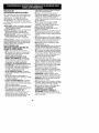
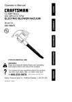
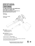
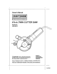
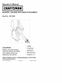
BLOWER / VACUUM WITH RAKE ATTACHMENT
Model
No. 900.74828
• Safety
A CAUTION:
• Assembly
Before using this product,
read this manual and follow
all its Safety Rules and
Operating Instructions.
Sears,
Roebuck
and Co., Hoffman
• Operation
• Maintenance
• Espa5ol, 12
Estates,
IL 60179
USA
www.sears.com/craftsman
Form No. 90534503
APR. '08
Printed in China
=]I(e_vivd
:::1-'i
D kv/±_e_lZIJ
_vA
I w]V±_-'_±Y_vAI
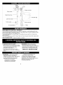
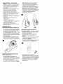
Upper vac tube
Power
¢[_
i
Upper blow tube_
Lower blow tube
Turbo nozzle __
%=' _,_
---"-----_-_
Air concentrator _
_ i
{-"]_1
lviv/-'lit i!-'I 1 / i'i
CRAFTSMAN TWO YEAR FULL WARRANTY
If this Craftsman product fails due to a defect in material or workmanship within two
years from the date of purchase, return it to any Sears store or other Craftsman outlet
in the United States for free replacement.
This warranty applies for only 90 days if this product is ever used for commercial or
rental purposes.
This warranty gives you specific legal rights, and you may also have other rights which
vary from state to state.
Sears, Roebuck and Co., Hoffman Estates, IL 61079
TO REDUCE RISK OF INJURY:
• Before any use, be sure everyone using
this toot reads and understands all safety
instructions and other information
contained in this manual.
• Save these instructions and review
frequently prior to use and in instructing
others.
_"]_l,]li[lit
-&WARNING: When using electric
gardening appliances, basic safety
precautions should always be followed to
reduce risk of fire, electric shock, and
personal injury, including the following:
READ ALL INSTRUCTIONS.
[,,,'I-'Iii _i i "l iviv/-'lit 1111[19
-&WARNING:
Some dust contains
chemicals known to the State of
California to cause cancer, birth defects
or other reproductive harm. Some
examples of these chemicals are:
• compounds in fertilizers
• compounds in insecticides,
herbicides and pesticides
• arsenic and chromium from
chemically treated lumber
To reduce your exposure to these
chemicals, wear approved safety
equipment such as dust masks that are
specially designed to filter out
microscopic particles.
SAFETY GUIDELINES
DEFINITIONS
-
It is important for you to read and
understand this manual.
The information it contains relates to
protecting YOUR SAFETY and
PREVENTING PROBLEMS. The symbols
below are used to help you recognize this
information.
•
•
IIDANGER:
Indicates an imminently
hazardous situation which, if not
avoided, will result in death or serious
injury.
IIWARNING:
Indicates a potentially
hazardous situation which, if not
avoided, could result in death or serious
injury.
&CAUTION:
Indicates a potentially
hazardous situation which, if not
avoided, may result in minor or
moderate injury.
CAUTION: Used without the safety
alert symbol indicates a potentially
hazardous situation which, if not
avoided, may result in property damage.
READ ALL INSTRUCTIONS
BEFORE USING BLOWER.
• READ and follow all instructions.
• DO NOT place inlet or outlet of vacuum
near eyes or ears when operating.
• THIS APPLIANCE IS PROVIDED WITH
DOUBLE INSULATION. Use only
identical replacement parts. See
instructions for servicing of double
insulated appliances.
• STORE IDLE TOOLS. When not in use,
the unit should be stored in a dry, high or
locked-up place - out of reach of
children.
• DON'T OVERREACH. Keep proper
footing and balance at all times.
• DO NOT pick up anything that is burning
or smoking, such as cigarettes, matches
or hot ashes.
• MAINTAIN TOOL WITH CARE. Keep
fan area clean for best and safest
performance. Follow instructions for
proper maintenance.
• DO NOT attempt to repair the
blower/vac. To assure product safety
•
•
•
•
•
•
•
•
•
•
•
•
•
•
and reliability, repairs, maintenance, and
adjustments should be performed by
Sears service centers or authorized
service stations, always using Sears
replacement parts.
DO NOT operate blower/vac in a
gaseous or explosive atmosphere.
Motors in these tools normally spark,
and the sparks might ignite fumes.
DO NOT use to pick up flammable or
combustible liquids such as gasoline or
use in areas where they may be present.
USE EXTRA CARE when cleaning on
stairs.
DO NOT leave appliance when plugged
in. Unplug from outlet when not in use
and before servicing.
DO NOT allow to be used as a toy.
Close attention is necessary when used
by or near children. Not recommended
for use by children.
DO NOT attempt to clear clogs from toot
without first unplugging it.
USE ONLY as described in this manual.
Use only manufacturer's recommended
attachments.
DO NOT use with damaged cord or plug.
If appliance is not working as it should,
has been dropped, damaged, left
outdoors, or dropped into water, return it
to a Sears Service Center.
DO NOT pull or carry by cord, use cord
as a handle, or pull cord around sharp
edges or corners. Keep cord away from
heated surfaces.
DO NOT unplug by pulling on cord. To
unplug, grasp the plug, not the cord.
DO NOT put any objects into openings.
Do not use with any opening blocked;
keep free of dust, lint, hair and
everything that may reduce air flow.
KEEP hair, loose clothing, fingers, and
all parts of body away from openings
and moving parts.
TURN OFF all controls before
unplugging.
DO NOT vacuum water, other liquids, or
wet objects. Never immerse any part of
the toot in liquid.
DO NOT handle plug or appliance with
wet hands.
KEEP CHILDREN, BYSTANDERS
AND ANIMALS AWAY from the work
areaaminimum
of30feet(10meters)
whenstarting
oroperating
thetoot.
• INSPECT
THEAREAbefore
usingthe
tool.Remove
alldebrisandhardobjects
suchasrocks,
glass,wire,etc.thatcan
ricochet,
bethrown,
orotherwise
cause
injuryordamage
during
operation.
Asa
vacuum,
thetootisdesigned
topickup
drymaterial
suchasleaves,
grass,
small
twigs,andbitsofpaper.
Donotvacuum
stones,
gravel,
metal,broken
glass,
etc.
•,WARNING:
SHOCK
HAZARD.
To
reduce
theriskofelectrical
shock;
do
notexpose
torain,donotuseonwet
surfaces.
Storeindoors.
&WARNING:
CUTHAZARD.
Turnoff
andunplug
unit,thenwaituntilfanstops
oratleast10seconds
before
removing
theblower
orvacuum
tubeassemblies.
• GROUND
FAULT
CIRCUIT
INTERRUPTER
(GFCI)
protection
should
beprovided
onthecircuit(s)
or
outlet(s)
tobeusedforthehedge
trimmer.
Receptacles
areavailable
having
built-in
GFCIprotection
andmay
beusedforthismeasure
ofsafety.
_kWARNING: To reduce the risk of
electric shock use only with an
extension cord intended for outdoor
use, such as SW-A, S0W-A, STW-A,
STOW-A, SJW-A, SJOW-A, SJTW-A or
SJTOW-A.
• EXTENSION CORD. Make sure your
extension cord is in good condition.
When using an extension cord be sure
it is heavy enough to carry the current
your product will draw. An undersized
extension cord will cause a drop in line
voltage resulting in loss of power and
overheating. The following table shows
the correct size to use depending on
cord length and nameplate ampere
rating. If in doubt, use the next heavier
gage. The smaller the gage number, the
heavier the cord.
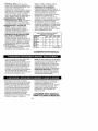
Minimum Gage for Extension Cords (AWG) 120 VAC Tools
26-50
51-100
105-150
Total Cord Length 0-25
(0-7,6m' (7,6-15,2m) (15,2-30,4m) (30,4-45,7m)
AWG
AWG
AWG
Amp Rating AWG
More than 0
18
16
16
14
Not More than 6
More than 6
18
16
14
12
Not More than 10
More than 10
16
16
14
12
Not more than 12
More than 12
14
12
Not Recommended
Not more than 16
SAVE
THESE
INSTRUCTIONS
V__.-.]':1=l::llnk'dl,V,
Vl:1;:i_ll_[e-I,.'_
_[olIIj:]llJ= II#[,."ll]_i_o]#l
Double insulated tools are constructed
throughout with two separate layers of
electrical insulation or one double
thickness of insulation between you and
the tool's electrical system. Tools built
with this insulation system are not
intended to be grounded. As a result, your
toot is equipped with a two prong plug
which permits you to use extension cords
without concern for maintaining a ground
connection.
NOTE: Double insulation does not take
the place of normal safety precautions
when operating this toot. The insulation
system is for added protection against
injury resulting from a possible electrical
insulation failure within the tool.
Replacement parts: When servicing all
tools, USE IDENTICAL REPLACEMENT
PARTS. Repair or replace damaged
cords.
Toreduce
theriskofelectric
shock,
this
equipment
hasapolarized
plug(one
bladeiswiderthantheother).
This
equipment
mustbeusedwithasuitable
polarized
2 wireor3wireextension
cord.
Polarized
connections
willfittogether
onlyoneway.Makesurethatthe
receptacle
endoftheextension
cordhas
largeandsmallbladeslotwidths.
Ifthe
plugdoesnotfitfullyintotheextension
ASSEMBLY
FOR BLOW
MODE
A, WARNING: Before attempting any of
the assembly steps below, ensure
product is switched off and disconnected
from the power supply.
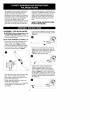
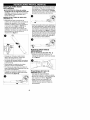
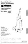
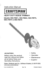
BLOW TUBE ASSEMBLY (FIGURES 1-4)
• Ensure fan cover grill is attached to the
power head. If not, attach cover as
shown in the inset of figure 1. NOTE:
Unit will not operate in blow mode without
fan cover grill in place. Align the upper
and lower tubes as shown in figure 1.
cord,reverse
theplug.Ifitstilldoesnot
fit,obtainasuitable
extension
cord.Ifthe
extension
corddoesnotfitfullyintothe
outlet,
contact
aqualified
electrician
to
install
theproper
outlet.Donotchange
thetootplugorextension
cordinany
way.
SAVE THESE INSTRUCTIONS
FOR FUTURE USE
• Push the tube assembly onto the power
head until it is in the fully locked position
(figure 2).
Use the air concentrator attachment to
target air flow to a tighter area. Add the
attachment to the assembly as shown in
figure 3. Push on until hole in tab
engages raised post on tube.
O
• Push the lower tube firmly into the upper
tube, until the tubes click into place.
• Blow tubes must be assembled to the
power head before use.
• Never operate without both lower and
upper tubes assembled.
• In the interest of safety, it is not intended
for the tubes to be separated once
assembled.
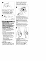
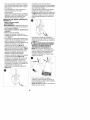
• Use the turbo nozzle attachment to
rapidly move air back and forth to
remove stubborn debris from grassy
areas. Add the tube to the assembly as
shown in figure 4. Push on until hole in
tab engages raised post on tube. To lock
the turbo nozzle attachment and reduce
the back and forth motion, pushforward on
the locking tab.
O
ASSEMBLY
MODE
FOR VACUUM
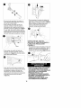
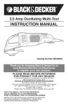
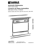
SHOULDER COLLECTION BAG
(FIGURE 5)
• Attach the shoulder collection bag to the
power head as shown in figure 5.
Wings
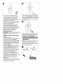
• To remove the rake from the vacuum
tube, lift up on the catch as shown in
figure 8 and pull the rake backwards to
release.
VACUUM TUBE ASSEMBLY
(FIGURES 6-10)
• Vacuum tubes must be assembled
together before use.
• Align the notches and the triangles on
upper and lower tubes. (figure 6)
O
O
• Remove the fan cover grill from the
bottom of the power head by pressing the
spring loaded release button (located on
the back of the power head) and pulling
the cover off (figure 9).
o /
• Push the lower tube firmly into the upper
tube, until the triangles click into place.
(Never operate apart).
• In the interest of safety, it is not intended
for the tubes to be separated once
assembled.
• To attach the rake to the vacuum tube,
slide the rake over the flat end of the
vacuum tube opentng as shown in figure
7. The "wings" of the rake must go under
the lip of the flat portion of the tube.
Continue to slide the rake toward the end
of the tube until you hear it "click" into place.
• Attach the vacuum tube assembly to the
power head (figure 10) by locating the
assembly as indicated by arrow, then
pivot about this point until the
locking/release catch is fully engaged.
G
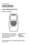
• To turn the tool ON, rotate the knob
clockwise. The further the knob is
rotated, the higher the air speed.
• To turn tool OFF, rotate the knob
counterclockwise to the off position (0).
O
REMOVING BLOW TUBE, VAC TUBE
OR COLLECTION BAG (FIGURE 11)
• To remove the blow tube, vac tube or
shoulder collection bag, depress the
release button on the power head and
pull straight off (figures 9 & 11).
[o] :,1:l-'r:_l / I #[_11 #F.'ll/-'tl_a.]l / [o] #F.
1
USE AS A BLOWER:
ALWAYS WEAR SAFETY GLASSES.
WEAR A FILTER MASK IF THE
OPERATION IS DUSTY. USE OF
RUBBER GLOVES AND SUBSTANTIAL
FOOTWEAR IS RECOMMENDED
WHEN WORKING OUTDOORS. FOR
HOUSEHOLD USE ONLY.
Z_WARNING: CUT HAZARD. When
turning the toot off for tube installation or
any other reason, wait 10 seconds for
the fan to stop rotating before
disassembly.
• Do not use in vacuum mode without the
vacuum tubes and collection bag in place.
• Always switch off and remove the plug
from the electrical supply when:
• Changing from blower to vacuum.
• The power supply cord has become
damaged or entangled.
• You leave btower/vac unattended.
• Clearing a blockage.
• Checking, adjusting, cleaning or
working on btower/vac.
• Use btower/vac only in daylight or good
artificial bight.
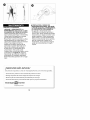
ON/OFF SWITCH (FIGURE 12)
Your blower vac is fitted with a variable
speed switch located on the top of the
power head below the handle.
CORD RETAINER (FIGURE 13)
• A cord retainer is incorporated into the
rear of the power head. It can be used in
two different ways:
• To use the cord retainer as shown in
figure 13A, hook the extension cord
under the retainer. Then plug the cord
from the power head into the extension
cord.
• To use the cord retainer as shown in
figure 13B, loop the extension cord over
the power head cord and plug the two
ends into each other. Then hook the
extension cord under the retainer.
13A
13B
BLOW MODE (FIGURE 14)
•,WARNING:
Ensure product is
switched off and disconnected from the
power supply.
• Fit fan cover grill as shown in figure 1.
• Attach the blow tube assembly to the
power head as shown in figure 2.
• Connect the cord on the power head to
the power supply (figure 13).
@
• Hold the blow tube approximately
7 inches (180 mm) above the ground,
turn the blower/vac on and using a
sweeping motion from side to side,
advance slowly keeping the accumulated
debris/leaves in front of you.
• Once you have blown the debris/leaves
into a pile, you can convert to vacuum
mode to collect the debris.
• Using the air concentrator will help
remove matted debris and leaves.
• Using the turbo nozzle attachment wilt
help move air back and forth to remove
stubborn debris from grassy areas.
VACUUM MODE (FIGURE 15)
USE AS A VACUUM:
AWARNING:
Ensure product is switched
off and disconnected from the power
supply.
To fit the shoulder collection bag to
product:
• Remove blow tube.
• Attach the shoulder collection bag to the
power head as shown in figure 5.
• Remove the fan cover from the bottom of
the power head by pressing the spring
loaded release button (located on the
back of the power head) and pulling the
cover off (figure 9).
• Attach the vacuum tube assembly to the
power head (figure 10) by locating the
assembly as indicated by arrow, then
pivot about this point until the
locking/release catch is fully engaged.
• Connect the cord on the power head to
the power supply (figure 13).
• Position the tube slightly above the
debris/leaves. Turn the blower/vac on,
then using a sweeping motion the
debris/leaves will be sucked up the tube,
mulched by the vacuum fan and
deposited into the collection bag
(figure 15).
As the bag fills the power of the suction
will decrease, turn the btower/vac off and
unplug from power supply.
@
• When using the rake attachment, push
down on the unit to bend the rake tines
as shown in figure 16. This will aid the
raking action and lower the vacuum tube
to allow the debris/leaves to be sucked
into the tube.
0
• Empty the shoulder collection bag by
sliding the retaining bar off the bottom of
the bag as shown in figure 17.
ACAUTION:
NEVER REMOVE THE
COLLECTION BAG WITHOUT FIRST
TURNING OFF AND UNPLUGGING
THE VACUUM.
NOTE: If the suction decreases and the
bag is not full, the vacuum tube is
probably clogged with debris. Turn off
and unplug the blower/vac and clear the
tube before continuing.
/
• To reattach the retaining bar, close the
bottom of the shoulder bag by folding
the bi-fotds flat as shown in figure 18.
Slide the retaining bar over the closed
bag.
/
[
i
CLEANING AND STORAGE
TURN OFF AND UNPLUG TOOL!
(Unplug extension cord at power
source.)
Use only mild soap and a damp cloth to
clean the toot. Clean out any clippings
which may have accumulated in the
Blower/Vac. When used properly with
dry leaves the fan chamber of your
Blower/Vac should remain clean. If
damp earth and debris are ingested
some of the particles may build up on
the inside of the fan chamber. If this
happens the performance of the unit wilt
decrease. This area can be cleaned out
using a wooden stick as shown in
figure 19 after disconnecting from the
power source. Your BtowerNac should
be stored in a dry place.
WARNING: SHOCK HAZARD. DO
NOT POUR OR SPRAY WATER ON
THE TOOL IN AN ATTEMPT TO
CLEAN.
Do not store the toot on or adjacent to
fertilizers or chemicals. Such storage
can cause rapid corrosion of the metal
parts.
Use only mild soap and a damp cloth to
clean the toot. Never let any liquid get
inside the toot; never immerse any part
of the toot into a liquid.
NEED MORE HELP?
You'll find the answer and more on managemyhome.com
o Find this and all your other product
manuals online.
o Get answers from our team of home experts.
o Get a personalized
o Find information
maintenance
plan for your home.
and tools to help with home projects.
manage[_
home
brought
to you by Sea_s
10
- for free!
Parts page
11
Cabezal
de _
impulsion
Tubo de aspirado inferior
Tubo de soplado
superior
Tubo de aspirado superior
..........
5_
_. .............. _'_
i
_
Tubo de soptado
:
/
I
/
/
i
j,
inferior
3
Botsa
Boquilla turbo __
?:'_
Concentrador
Rastrillo
DOS AI_IOS DE GARANT|A COMPLETA PARA LAS HERRAMIENTAS CRAFTSMAN
Siesta herramienta Craftsman falta debido a defectos en el material o en la fabricacion
dentro det dos aRos de ta fecha de compra, devuetvala a cualquier tienda Sears u otro
punto de venta de productos Craftsman en Estados Unidos para recibir gratis una
herramienta de reemptazo.
Esta garantia se aptica solo por 90 dias si este producto se utiliza con fines
comerciates o de atquiler.
Esta garantia te concede derechos legales especificos; pueden existir otros derechos
_ue varian segun et estado.
ears, Roebuck and Co., Hoffman Estates, IL 60179
PARA REDUCIR EL RIESGO DE LESIONES:
• Antes de cuatquier uso, asegurese que
cuatquier persona que vaya a utilizar esta
herramienta tea y comprenda todas tas
instrucciones de seguridad y la
informacion conten_a en este manual.
• Conserve estas instrucciones y repaselas
con frecuencia antes de usar la
herramienta e instruir a otras personas.
&ADVERTENCIA:
Siempre que utilice
herramientas electricas de jardina debe
seguir ciertas precauciones bb.sicas de
seguridad, a fin de reducir los riesgos de
incendio, choque electrico y tesiones
personates, entre las que se encuentran
las siguientes.
LEA TODAS I_AS INSTRUOOIONES.
• compuestos en insecticidas, herbicidas
y pesticidas
• arsenico y cromo de madera tratada
quimicamente
Para reducir su exposicion a estos
quimicos, utitice equipo de seguridad
aprobado como mascaras contra potvo
dise_adas especificamente para fll"trar
particutas microscopicas.
_,ADVERTENClA:
Parte det potvo
originado por este producto contiene
quimicos queen el Estado de California
se consideran como causantes de
cancer, defectos congenitos u otros
da5os reproductivos. Algunos ejemplos
de estos quimicos son:
• compuestos en fertilizantes
12
autorizadas y siempre deben utitizarse
piezas de repuesto Sears.
• NO opere el soptador/aspiradora en
atm6sferas gaseosas o explosivas. Los
motores en estas unidades producen
chispas en condiciones normales, y
estas chispas pueden originar la ignici6n
de los vapores.
• NO se utitice para recoger liquidos
combustibles o infiamabtes como
gasotina, ni se utilice en &reas en las
que puedan estar presentes.
• TENGA MUCHO CUlDADO cuando
limpie en escatones.
• NO deje el aparato cuando este conectado.
Desconectelo de la toma de corriente
cuando no este en uso y antes de darte
servicio.
• NO permita que se utilice como juguete.
Se requiere atenci6n cercana cuando se
utilice por nifios o cerca de ellos. No se
recomienda para ser usada pot nifios.
• NO intente limpiar la unidad sin antes
desconectarla.
• USESE SOLAMENTE como se describe
en este manual. Solamente utitice los
dispositivos recomendados por el fabricante.
• NO Io use con un cable o enchufe dafiados.
Si el aparato no funciona como deberia,
se ha caido, dafiado, dejado at aire libre
o sumergido en agua, devuelvato a un
centro de mantenimiento Sears.
• NO tire del cable ni cargue la
herramienta por este, no lo utitice como
asa ni to cotoque sobre bordes o aristas
afilados. Atejeto de superficies calientes.
• NO desconecte tirando det cable. Para
desconectar, tire de ta ctavija, no del cable.
• NO coloque ningun objeto en las
aberturas. No se use con ninguna
abertura btoqueada; conservelas tibres
de polvo,petusas y cuatquier objeto que
pueda reducir el flujo de aire.
• CONSERVE cabelto, cabelto, ropas
fiojas, dedos y dem&s partes del cuerpo
atejados de aberturas y partes m6viles.
• APAGUE todos los controtes antes de
desconectar la unidad.
• NO aspire agua, otros tiquidos u objetos
humedos. Nunca sumerja ninguna parte
de la herramienta en ningun h'quido.
• NO maneje la ctavija ni otra parte de la
unidad con las manos humedas.
• CONSERVE A LOS NII_iOS,
ESPECTADORES Y ANIMALES
ALEJADOS del b.rea de trabajo, a un
minimo de 10 metros cuando encienda u
opere la unidad.
PAUTAS DE
SEGURIDAD/DEFINICIONES
Es importante que lea y comprenda este
manual. La informacion que contiene se
relaciona con la proteccion de SU
SEGURIDAD y la PREVENClON DE
PROBLEMAS. Los simbotos que siguen
se utilizan para ayudarto a reconocer esta
informacion.
-& pELIGR. O: indica una sitq.acion de peligro
_nmJnen[,eq.ue,s_no se ew[a, provocara _a
muer[e o Jes_onesgraves.
• ,ADVERTENClA:
indica una situacion de
peligro potencial que, si no se evita,
provocarb, la muerte o lesiones graves.
A PRECAUCION:
indica una situacion de
peligro potencial que, si no se evita,
provocar& lesiones teves o moderadas.
PRECAUCION: utitizado sin el simboto de
aterta de seguridad indica una situacion de
peligro potencial que, si no se evita, puede
provocar dafios en la propiedad.
LEA TODAS LAS
INSTRUCCIONES
ANTES
USAR EL SOPLADOR
DE
• LEA y siga todas las instrucciones.
• NO cotoque la entrada o la satida de la
aspiradora cerca de sus ojos u oidos
cuando este en operacion.
• ESTE APARATO CUENTA CON
DOBLE AISLAMIENTO. Sotamente
utilice refacciones identicas. Consutte
las instrucciones sobre el servicio
a aparatos con doble aislamiento.
• GUARDE LAS HERRAMIENTAS QUE
NO EMPLEE. Cuando no utitice ta
herramienta, esta deber& guardarse en
un tugar seco y etevado o bajo ttave,
fuera del atcance de los nifios.
• NO SE SOBREEXTIENDA. Conserve
siempre bien apoyados los pies asi como
el equilibrio.
• NO recoja objetos en combusti6n o
humeantes, tales como cigarrillos, ceritlos
o cenizas catientes.
• CUlDE LA HERRAMIENTA. Conserve
limpia la zona det ventitador para que
funcione mejor y de manera mas segura.
Siga las instrucciones
para et mantenimiento apropiado.
• NO intente reparar la aspiradora/sopladora.
Para garantizar la seguridad y la
confiabitidad del producto, tas
reparaciones, et mantenimiento y los
ajustes deben estar a cargo de los
centros de mantenimiento Sears, o de
las estaciones de mantenimiento
13
• REVISE EL AREA antes de usar ta
unidad. Etimine todos los objetos duros
como rocas, vidrios,alambres, etc., que
puedan satir despedidos y por
consiguiente, causar lesiones durante la
operaci6n. Como aspiradora, la unidad
esta disefiada para recoger materiates
secos como hojas, pasto, pequefias
varas y trozos de papel. No aspire piedras,
grava, metates, trozos de vidrio, etc.
-4,ADVERTENCIA;
RIESGO DE
DESCARGA ELECTRICA. Para reducir
el riesgo de choque etectrico; no se
exponga a ta Iluvia, no se utilice sobre
superficies mojadas. Gub.rdese bajo techo.
-&ADVERTENCIA:
PELIGRO DE
CORTE. Apague y desconecte ta
unidad, despues, espere a que et
ventitador se detenga o at menos 10
segundos antes de desmontar los
subensambtes de aspirado o del soptador.
• INTERRUPTOR DE ClROUlTO PARA
FALLAS EN LA TIERRA (GFCI) Se
debe proporcionar proteccion a los
circuitos o clavijas que se usarb.n con la
podadora de setos. Existen contactos con
proteccion GFCI integrada y se pueden
utilizar para esta medida de seguridad.
• ,ADVERTENCIA: Para reducir el riesgo
de choque etectrico, utilicese sotamente
con cables de extension para
intemperie, como los siguientes: SW-A,
SOW-A, STW-A, STOW-A, SJW-A,
SJOW-A, SJTW-A o SJTOW-A.
• CORDONES DE EXTENSION.
Asegurese que su extension este en
buenas condiciones. Cuando utilice una
extension, asegurese que tenga el
calibre suficiente para conducir la
corriente que su herramienta necesita.
extension con calibre menor al
necesario causara una caida en el
voltaje de la linea, resuttando en perdida
de potencia y sobrecalentamiento. La
tabla siguiente muestra et calibre
correcto para usarse, de acuerdo con la
Iongitud de la extension y el amperaje en
la placa de identificacion. Si tiene dudas,
utilice el calibre siguiente. Mientras
menor sea el numero del calibre, mayor
sera la capacidad del cable.
Calibre minimo para cordones de extension
(AWG) 120 V ca herramientas
Longitudtotalenmetros
0-7.62
-15.24
-30.48
-45.72
AMPERAJE
AWG
AWG
AWG
AWG
Masde
0
18
16
16
14
No mas de
6
Masde
6
No mas de
10
18
16
14
12
Masde
No mas de
10
12
16
16
14
12
Mas de
12
14
12
No mas de
16
CONSERVE
No
Recomendado
ESTE MANUAL
Las herramientas con dobte aislamiento
estan construidas con dos capas
separadas de aistamiento etectrico o una
capa de espesor doble entre usted y el
sistema electrico de la herramienta. Las
herramientas con doble aistamiento no
necesitan conectarse a tierra. Como
resultado, su herramienta esta. equipada
con una clavija de dos patas que le
permite utilizar extensiones sin preocuparse
por tener una conexion a tierra.
NOTA: El dobte aistamiento no reemptaza
las precauciones normates de seguridad
cuando se opere la herramienta. Et
sistema de aistamiento te proporciona
proteccion afiadida contra las lesiones
resuttantes de posibles fatlas en el
aistamiento electrico de la herramienta.
PARTES DE REPUESTO: Solamente
emptee refacciones identicas cuando
haga servicio. Repare o reemplace los
cordones electricos dafiados.
Este equipo cuenta con una ctavija
potarizada (con una pata m&s ancha que
la otra) para reducir el riesgo de choque
electrico. El equipo debe utilizarse con
una extensi6n adecuada de 2 o 3 cables.
Las conexiones potarizadas sotamente
ajustan de una manera. Asegurese que
a conexi6n hembra de la extensi6n
tenga una ranura grande y una mas
pequefia. Si ta ctavija no se ajusta
completamente a la extension, inviertala.
Si aun asi no ajusta, consiga una
extension adecuada. Si la extension no
se ajusta por compteto a la toma de
corriente comuniquese con un
electricista catificado para que le instale
la toma de corriente adecuada. Por
ningun motivo cambie la ctavija en ta
herramienta o en ta extension de
ninguna manera.
CONSERVE ESTE MANUAL
PARA FUTURAS CONSULTAS.
14
• Utilice et accesorio concentrador de aire
para dirigir et flujo de aire hacia un area
mas estrecha. Conecte el accesorio al
conjunto, como se muestra en la figura
3. Empuje hasta que el orificio de ta ficha
encaje en el poste mb.s alto del tubo.
MONTAJE PARA MODO
SOPLADORA
AADVERTENCIA:
Antes de realizar
cualquiera de los siguientes pasos de
montaje, asegurese de que el producto
este apagado y desconectado de la
fuente de energia.
MONTAJE DEL TUBO DE SOPLADO
(FIGURAS 1-4)
• Asegurese de que la parritia de ta
cubierta del ventilador este conectada al
cabezal de impulsion. Si no 1oest&,
conecte la cubierta como se muestra en
el recuadro de la figura 1. NOTA: La
unidad no funcionar& en modo de
soptado si la parrilla de ta cubierta del
ventilador no est& en su lugar. Atinee los
tubos superior e inferior como se
muestra en ta figura 1.
• Utilice el boquilta turbo para desptazar el
aire hacia adetante y hacia atra.s y quitar
los desechos mas rebeldes de las areas
con cesped. Conecte el tubo at conjunto,
como se muestra en la figura 4. Empuje
hasta que et orificio de ta ficha encaje en
et poste mb.s alto det tubo. Para btoquear
et boquilla turbo y reducir el movimiento
hacia adelante y hacia atrb.s, empuje la
ficha de btoqueo hacia adelante.
O
O
MONTAJE PARA MODO
ASPIRADORA
BOLSA DE RECOLECCION (FIG. 5)
• Conecte la botsa de recoieccion at
cabezat de impulsion, como se muestra
en ta figura 5.
• Empuje con firmeza el tubo inferior
dentro det tubo superior, hasta que
ambos se ajusten en su lugar.
• Los tubos de soptado deben conectarse
at cabezal de impulsion antes de utilizar
la herramienta.
• Nunca opere la unidad sin los tubos
superior e inferior ensambtados.
• Por motivos de seguridad, los tubos no
est&n diseffados para separarse una vez
que esta.n ensambtados.
• Empuje et conjunto de tubos sobre el
cabezal de impulsion hasta que encaje
perfectamente (figura 2).
Ensamblaje
del tubo
aspiraao (FIG. 6 - 10)
de
• Los tubos de aspirado deben
ensambtarse entre si antes de usarse.
• Alinear tas muescas y los triangulos del
tubo superior e inferior. (figure 6)
• Haga coincidir las muescas y los
triangutos en los tubos superior e
inferior. (Nunca opere sin haberlos
ensambtado.)
15
O
O
Para conectar et conjunto de tubos de
aspirado al cabezal de impulsion (figura
10), cotoque et conjunto como 1oindica la
flecha y luego gire sobre este punto
hasta que el pestillo de bloqueo y
liberacion encaje perfectamente.
• En aras de la seguridad, los tubos no
estan hechos para separarse una vez
que se han ensambtado.
• Para conectar el rastrilto al tubo de
aspirado, destice el rastrillo sobre el
borde ptano de ta abertura del tubo de
aspirado, como se muestra en la figura
7. Las "alas" del rastrillo deben quedar
debajo det borde de la porci6n plana del
tubo. Destice el rastritlo hacia et extremo
del tubo hasta que se ajuste en su tugar.
EXTRACCI()N DEL TUBO DE
SOPLADO, EL TUBO DE ASPIRADO O
LA BOLSA DE RECOLECCI()N
(FIGURA 11)
• Para extraer el tubo de soptado, el tubo de
aspirado o ta bolsa de recotecci6n, oprima
et bot6n de tiberaci6n del cabezat de
imputsi6n y tire hacia afuera (figura 9 & 11).
• Para extraer el rastrilto del tubo de
aspirado, levante el pestitlo, como se
muestra en la figura 8, y tire del rastrillo
hacia atrb.s para liberarlo.
0
PARA UTILIZAR COMO SOPLADORA:
UTILICE SIEMPRE ANTEOJOS DE
SEGURIDAD. UTILICE UNA M.ASCARA
CON FILTRO Sl LA OPERAClON
PRODUCE POLVlLLO. SE
RECOMIENDA UTILIZAR GUANTES
DE GOMA Y CALZADO CERRADO DE
MATERIAL RESlSTENTE AL
TRABAJAR AL AIRE LIBRE. PARA
USO DOMf=STICO SOLAMENTE.
• Para retirar la parritta de la cubierta del
ventilador de ta parte inferior det cabezal
de impulsion, presione el boton de
liberacion con resorte (ubicado en la
parte posterior del cabezal de impulsion)
y tire de la cubierta para extraerla
(figura 9).
16
_,ADVERTENClA:
PELIGRO
DE
CORTE.
AIapagar
laherramienta
para
instatar
lostubosoporcualquier
otro
motivo,
espere
10segundos
hastaque
elventilador
dejedegirarantes
de
desarmada.
• Nolautiliceenmodoaspiradora
silos
tubosdeaspirado
ylabolsade
recotecci6n
noestanensutugar.
• Apague
siempre
taherramienta
y
desenchufela
deltomacordente
cuando:
• Cambie
demodo
soptadora
a modo
aspiradora.
• Elcabledealimentaci6n
estedafiado
o
enredado.
•Dejelaaspiradora/soptadora
sin
supervisi6n.
•Elimine
unaobstruccion.
•Verifique,
ajuste,
limpie
otrabaje
enta
aspiradora/soptadora.
• Utilice
laaspiradora/sopladora
sotamente
contaluzdeldiaoconuna
buena
luzartificial.
INTERRUPTOR
13A, enganche et cable prolongador
debajo det dispositivo de retencion.
Luego conecte el cable det cabezal de
impulsion at cable protongador.
Para utilizar el dispositivo de retencion
del cable como se muestra en la figura
13B, conecte et extremo det cable
prolongador con el extremo del cable del
cabezal de impulsion. Luego enganche
el cable protongador debajo del
dispositivo de retencion.
DE
13A
ENCENDIDO/APAGADO
(FIGURA 12)
Su aspiradora soptadora esta. equipada
con un interruptor de velocidad variable
ubicado en la parte superior del cabezal
de imputsi6n, debajo det mango.
• Para ENCENDER ta herramienta, gire la
peritla en sentido de tas agujas del retoj.
Cuanto mas gire la perilla, mayor sera la
vetocidad del aire.
• Para APAGAR ta herramienta, gire la
perilla en sentido contrado a tas agujas
del reloj hasta la posici6n de apagado (0).
13B
MODO SOPLADORA (FIGURA 14)
• ,ADVERTENCIA:
Asegurese de que et
producto este apagado y desconectado
de la fuente de energia.
• Coloque ta parritla de la cubierta del
ventilador como se muestra en la
figura 1.
• Conecte el conjunto de tubos de soplado
at cabezat de impulsi6n, como se
muestra en la figura 2.
• Conecte el cable del cabezat de impulsi6n
a la fuente de energia (figura 13).
O
@
DISPOSlTIVO DE RETENCI(_N DEL
CABLE (FIGURA 13)
• La parte posterior del cabezal de
impulsi6n tiene un dispositivo incorporado
de retencion del cable. Puede utilizarse
de dos maneras diferentes:
• Para utilizar el dispositivo de retencion
del cable como se muestra en ta figura
Sostenga et tubo de soplado a
aproximadamente 178 mm (7 pulgadas)
del piso, encienda ta aspiradora/soptadora
y avance tentamente, con un movimiento
de barrido de tado a lado, y mantenga
los residuos y las hojas acumutadas
delante suyo.
17
• Unavezquehayasoplado
losresiduos
ylashojashastaformar
unapila,podra
pasar
amodoaspiradora
pararecoger
losresiduos.
• Elconcentrador
deaireloayudara
a
quitarlosresiduos
ylashojas
enmarafiados.
• Eldispositivo
boquilta
turbo1oayudara
a
desptazar
elairehaciaadelante
yhacia
atrAs
paraquitarlosdesechos
mAs
rebeldes
delasAreas
concesped.
MODELOS CON MODO ASPIRADORA
(FIGURA 15)
PARA UTILIZAR COMO
ASPIRADORA:
AADVERTENCIA:
Asegurese de que et
producto este apagado y desconectado
de la fuente de energia.
Para anexar la bolsa de recoleccion al
producto:
• Retire el tubo de soptado.
• Conecte la botsa de recoleccion at
cabezat de impulsion, como se muestra
en la figura 5.
• Para retirar la cubierta del ventilador de
la parte inferior det cabezat de impulsion,
presione el boton de liberacion con
resorte (ubicado en la parte posterior del
cabezal de impulsion) y tire de la
cubierta para extraerta (figura 9).
• Para conectar et conjunto de tubos de
aspirado at cabezal de impulsion (figura
10), cotoque el conjunto como Io indica
la flecha y luego gire sobre este punto
hasta que el pestillo de btoqueo y
liberacion encaje perfectamente.
• Conecte el cable det cabezat de impulsion
a la fuente de energia (figura 13).
• Cotoque et tubo apenas por encima de
los residuos y las hojas. Encienda la
aspiradora/soptadora; luego con un
movimiento de barrido, el tubo aspirara
los residuos y las hojas, el ventilador de
la aspiradora los triturara y los
depositara en ta botsa de recoteccion
(figura 15).
A medida que ta bolsa se ltene, la
potencia de succion disminuira; apague
la aspiradora/soptadora y desenchufela
de ta fuente de energia.
Cuando utilice el accesorio de rastrillo,
presione la unidad para doblar los
dientes det rastritto, como se muestra en
la figura 16. Esto facilitara la accion de
rastrillado y bajara el tubo de aspirado
para que pueda aspirar los residuos y
hojas.
• Para vaciar la botsa de recoleccion,
deslice ta barra de retencion de la parte
inferior de ta botsa, como se muestra en
la figura 17.
A PRECAUCION: NUNCA EXTRAIGA
LA BOLSA DE RECOLECCION SIN
APAGAR Y DESENCHUFAR LA
ASPIRADORA PREVIAMENTE.
NOTA: Si la succion disminuye y la
bolsa no esta Ilena, es probable que el
tubo de aspirado este obstruido con
residuos. Apague y desenchufe la
aspiradora sopladora y limpie el tubo
antes de continuar.
0
• Para votver a colocar la barra de
retenciOn, cierre la parte inferior de la
botsa ptegando la parte plana ptegabte,
como se muestra en la
figura 18. Destice la barra de retencion
sobre la botsa cerrada.
18
A, PRECAUCION: RIESGO DE
DESCARGA ELECTRICA. NO VACiE
O ROCIE AGUA EN LA HERRAMIENTA
EN UN INTENTO POR LIMPIARLA.
No guarde la herramienta sobre
fertitizantes o productos quimicos ni
junto a ellos. Dicho atmacenaje puede
ocasionarte una rapida corrosion alas
partes metalicas. Utilice 0nicamente
jabon suave y un trapo humedo para
limpiar la herramienta. Nunca permita
que se introduzcan liquidos en la
herramienta; nunca sumerja ninguna
parte de la herramienta en ningun
liquido.
LIMPIEZA Y GUARDADO
APAGUE Y DESCONECTE LA
HERRAMIENTA (desconecte el cable
de extension de la toma de corriente).
Utilice 0nicamente jabon suave y un
trapo h0medo para timpiar la herramienta.
Limpie todos los desechos y recortes
que se hayan acumulado en su
BtowerNac. Cuando la unidad se utiliza
apropiadamente con hojas secas, la
camara del ventilador debe permanecer
limpia. Si se trabaja con tierra y
desechos humedos, algunas de las
)articutas se pueden acumular en el
interior de ta camara det ventilador.
Si esto ocurre, el rendimiento de la
unidad bajara. Esta parte puede
limpiarse con una vara de madera, como
se muestra en ta figura 19, luego de
desconectar ta unidad de ta fuente de
atimentacion.Su soplador aspiradora
BlowerNac debe guardarse en un tugar
seco.
iNECESITA MAS AYUDA?
Encontrara" respuestas
y ma's en managemyhome.com
en forma
• Encuentre _ste y todos losotros manuales de productos en linea.
• Obtenga respuestas de nuestro equipo de expertos en el hogar.
• Reciba un plan de mantenimiento personalizado para su hogar.
• Encuentre informaci6n y herramientas 0tiles para sus proyectos dom_sticos.
manage[
home
Auspiciado
por Sears
19
gratuita.
Your
For expert troubleshooting
anage
Home
and home solutions advice:
home
www,managemyhome,com
For repair - in your home - of all major brand appliances,
lawn and garden equipment, or heating and cooling systems,
no matter who made it, no matter who sold it !
For the replacement parts, accessories and
owner's manuals that you need to do-it-yourself.
For Sears professional installation of home appliances
and items like garage door openers and water heaters.
1-800-4-MY-HOME
®
Ca, anytime,
(1-800-469-4663)
(U.S.A.
www.sears.corn
day or night
and Canada)
www.sears.ca
Our Home
For repair of carry-in items like vacuums, lawn equipment,
and electronics, call anytime for the location of the nearest
Sears Parts & Repair Service Center
1=800-488=1222 (U.S.A.)
www,sears=com
1=800=469=4663 (Canada)
www.sears.ca
To purchase a protection agreement on a product serviced by Sears:
1-800-827-6655
(u.s._)
1=800=361=6665 (Canada)
Para pedir servido de reparaci6n
a domicilio, y para ordenar piezas:
I..888-SU-HOGAR®
OL
O .C __7w
Au Canada pour service en frangais:
(I-888-784-.6427)
@ Sears Brands, LLC
® Registered
® Marca
MCMarque
Trademark
Registrada
/ TM Trademark
I TM Marca
de commerce
/ SMService
de Fabrica
/ MDMarque
/ SMMarca
d6posee
2O
Mark of Sears
de Servicio
de Sears
Brands,
Brands,
de Sears
LLC
LLC
Brands,
LLC