1
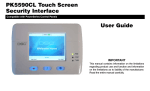
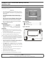
PK5590CL Color Touchscreen Security Interface
Installation Guide
Touch-sensitive Colour LCD Display. Compatible on partition 1 of single-partition PowerSeries control panels.
The PK5590CL Touchscreen is a touch-sensitive color LCD Interface. This
keypad provides interactive operation for the User of PowerSeries alarm panels (programmed for partition 1).
Figure 1, Front View
IMPORTANT:
•
Alarm Panel programming must be performed with a PowerSeries
Keypad. The PK5590CL is intended for User programming functions
and operations.
•
This Installation Guide shall be used in conjunction with the
CONTROL PANEL Installation Manual to which this equipment is
connected.
•
This device is powered from a Limited Power supply. The wiring
and/or cables used to connect the PK5590CL Touchscreen shall be
insulated with PVC, TFE, PTFE, FEP, neoprene or polyimide.
•
Refer to the associated User Guide and Alarm Panel installation
manual for additional information.
Specifications
Operating Voltage Range ..............................9.5 - 24.0 VDC
Current Consumption ................................... 320 mA (max.)
Operating Temperature Range......... 14°-122°F(-10°+50°C)
Humidity ........................... 85%, RH non-condensing (max)
Out of the Box
Touch Panel Display............................................. Qty 1
User Guide........................................................... Qty 1
This Installation Guide ......................................... Qty 1
Figure 2, Back View
Installation
1.
Select a mounting location in the drywall between two studs.
Ensure that there is at least 1.5” clearance from the outer edge of
the back box and the nearest stud.
2.
Cut a hole in the drywall using the template provided (Fig 3).
3.
Route the 4-conductor keybus wire out from the wall.
NOTE: Use 22AWG wire only (9.5VDC min. required for Touchscreen).
4.
Connect the Programming Keypad (PK5500) to the keybus and
program Panel as indicated (see Programming). Do NOT remove
the keypad when programming is completed.
5.
Remove the front bezel from the PK5590CL. Insert a small slotted
screwdriver between the cover and plastic backplate and gently
pry apart exposing screws for the drywall tabs.
6.
Enter [,][8] Installer Code [902]. Quickly remove Programming
Keypad and install the PK5590CL described in Step 7 (This must
be done within 30 seconds.
7.
Connect the four Keybus wires to the terminals on the back of the
unit in the locations indicated.
8.
Position the unit in the wall cut out and secure using the two
mounting screws and drywall tabs.
9.
Replace the front bezel by snapping in place.
Drywall Tabs
10. Verify Correct Operation. Refer to the PK5590CL User Guide.
NOTE:
Auto-arming is not supported on this command output panel.
Function Key 1 is used for Output Command 1, Function Key 2 is used for Command Output 2.
4-wire Keybus Connection
Figure 3 Mounting Hole Template
Drill 4 holes in the positions indicated
using a 3/8” (9.5mm) drill bit
Mounting Hole Template
4.0” (10 cm)
NOTE:
Ensure cut out is 1.5 inches (4 cm)
minimum from nearest stud to enable
correct operation of drywall fasteners
FCC Compliance Statement
Limited Warranty
Caution: Changes or modifications not expressly approved by Digital Security Controls could void your authority
to use this equipment.
This equipment generates and uses radio frequency energy and if not installed and used properly, in strict accordance
with the manufacturer’s instructions, may cause interference to radio and television reception. It has been type tested and
found to comply with the limits for Class B device in accordance with the specifications in Subpart “B” of Part 15 of
FCC Rules, which are designed to provide reasonable protection against such interference in any residential installation.
However, there is no guarantee that interference will not occur in a particular installation. If this equipment does cause
interference to television or radio reception, which can be determined by turning the equipment off and on, the user is
encouraged to try to correct the interference by one or more of the following measures:
Digital Security Controls warrants that for a period of 12 months from the date of purchase, the product shall be free
of defects in materials and workmanship under normal use and that in fulfilment of any breach of such warranty,
Digital Security Controls shall, at its option, repair or replace the defective equipment upon return of the equipment
to its repair depot. This warranty applies only to defects in parts and workmanship and not to damage incurred in
shipping or handling, or damage due to causes beyond the control of Digital Security Controls such as lightning,
excessive voltage, mechanical shock, water damage, or damage arising out of abuse, alteration or improper application of the equipment.
The foregoing warranty shall apply only to the original buyer, and is and shall be in lieu of any and all other warranties, whether expressed or implied and of all other obligations or liabilities on the part of Digital Security Controls.
Digital Security Controls neither assumes responsibility for, nor authorizes any other person purporting to act on its
• Re-orient the receiving antenna
behalf to modify or to change this warranty, nor to assume for it any other warranty or liability concerning this prod• Relocate the alarm control with respect to the receiver
uct.
• Move the alarm control away from the receiver
In no event shall Digital Security Controls be liable for any direct, indirect or consequential damages, loss of antici• Connect the alarm control into a different outlet so that alarm control and receiver are on different circuits.
If necessary, the user should consult the dealer or an experienced radio/television technician for additional suggestions. pated profits, loss of time or any other losses incurred by the buyer in connection with the purchase, installation or
The user may find the following booklet prepared by the FCC helpful: “How to Identify and Resolve Radio/Television operation or failure of this product.
Interference Problems”. This booklet is available from the U.S. Government Printing Office, Washington, D.C. 20402, Warning: Digital Security Controls recommends that the entire system be completely tested on a regular basis. However,
Stock # 004-000-00345-4.
despite frequent testing, and due to, but not limited to, criminal tampering or electrical disruption, it is possible for this
product to fail to perform as expected.
Important Information:Changes or modifications not expressly approved by Digital Security Controls could void the
This Class B digital apparatus complies with Canadian ICES-003.
user’s authority to operate this equipment.
Cet appareil numérique de la classe B est conforme à la norme NMB-003 du Canada.
2 9 0 0 7 2 8 2 R0 0 3
©DSC 2007 Printed in Canada