1
GE Monogram
_
36" Built-In
Refrigerators
Custom
Options
Guide
and
Installation
Instructions
With
Custom
and Trim
Kit
Installation
Models:
These
Monogram
designed
built-in
to be customized
door and grille panels.
panels
are
with decorator
installed
panels
Lexan _ and Stainless
Optional
range
ZISB36D
trim will accommodate
1/4" thick custom
or optional
Steel panel
kits.
trim kits allow an even broader
of custom
appearance
this booklet carefully
desired appearance
options.
to accomplish
and to insure
the
a trouble free
installation.
This booklet
contains
information
illustrations
to demonstrate
possibilities.
Custom
and
custom
door and grille panel
sizes vary to accommodate
the kit being
used. Dimensions
for each application
are
included and can be faxed or sent to the
cabinet
manufacturer
be constructed
so that the panels
accurately.
ZIS36N
ZISW36D
Field installed
are required.
Factory
Read
refrigerators
can
Panel Dimensions
Instructions
Before you begin - Read these instructions
completely
and carefully.
IMPORTANT - Save these instructions for local inspector's use.
IMPORTANT - OBSERVE ALL GOVERNING CODES AND ORDINANCES.
Note to Installer
- Be sure to leave these instructions
Note to Consumer
- Keep these instructions
vivl_,
___
This appliance
lib III _1i_ II li [|]
with the Consumer.
with your Use and Care Book for future reference.
must be properly
If you received a damaged refrigerator, you should
immediately contact your dealer or builder.
is the responsibility
Product failure due to improper
covered
See "Grounding
under the GE Appliance
Use & Care Guide for warranty
of the installer.
installation
Warranty.
page 15.
• Use this appliance only for its intended purpose.
Immediately repair or replace electric service
cords that have become frayed or damaged.
• Unplug the refrigerator
before cleaning or making
repairs.
Repairs should be made by a qualified service
technician.
is not
See the
information.
For Monogram local service in yourarea,
1-800-444-1845.
For Monogram service in Canada, 1-888-880-3030.
For Monogram Parts andAccessories, call
1-800-626-2002.
• II ne faut utiliser cet appareil que pour I'usage pour
lequel il a ere construit,
• II faut reparer ou remplacer immediatement tout
cordon d'alimentation
electrique effiloche ou
endommage.
• Debrancher le refrigerateur
avant le nettoyage ou
toute intervention,
• Les reparations doivent
technicien qualifie.
Contents
the Refrigerator,"
i_ II Cet appareil dolt _tre correctement mis a la terre.
Consulter <<Mise a terre du refrigerateur >>,page 15.
If you have a question concerning the installation of this
product, call the GEAnswer CenterCR_
Consumer
Information Service at 800.626.2000,24 hours a day,
7 days a week.
Proper installation
grounded.
etre faites par un
Design Information
Advance Planning for a Flush Installation ...................................................................................................................................
Cutout and Product Dimensions ..................................................................................................................................................
3
3
Installation
Between
Base & Wall Cabinets .............................................................................................................................
4
Installation
At End-of-Run .............................................................................................................................................................
4
Frameless Cabinets ........................................................................................................................................................................
4
Accessory
4
Panel Kits .....................................................................................................................................................................
Advance Planning, Exterior Appearance
Options ......................................................................................................................
Appearance Examples, Trim Kit Descriptions
Custom Panel Dimensions
...........................................................................................................................
ZIS36N ............................................................................................................................................................................................
ZISW36D, ZIBB36D ..................................................................................................................................................................
5
5
6-9
10-13
Side Panel or Filler Options ........................................................................................................................................................
14
Installation
Instructions ...........................................................................................................................................................
15-20
Trim Kits
ZKH1 Trim Kit Installation Instructions
Custom Handles with 1/4" Thick Panels .............................................................................................................................
ZG2 Trim Kit Installation
21-25
Instructions
Grille Panel Frame Adjustment ..................................................................................................................................................
ZKT36 Trim Kit installation Instructions
26
3/4" Thick Custom Panels .......................................................................................................................................................
ZKHT1 Trim kit Installation Instructions
27-32
Custom Handles with 3/4" Thick Panels ..............................................................................................................................
33-37
ZKHSS1 Trim Kit Installation
Tubular Stainless
Instructions
Steel Handles for 1/4" Panel Installation
............................................................................................
38-41
ZKHTSB1 Trim Kit Installation Instructions
Tubular Stainless Steel Handles for 3/4" Panel Installation
............................................................................................
42-45
ZWCD1 Trim Kit Installation
Instructions
Custom Dispenser Collar ........................................................................................................................................................
46-47
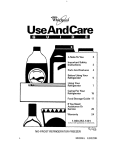
Design
Information
36 " Built-In
Advance
Flush
Refrigerator
Planning
or
Semi-Flush
Enclosure
Installations
/
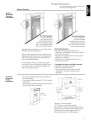
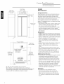
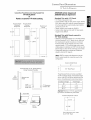
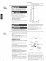
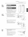
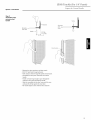
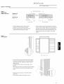
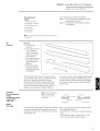
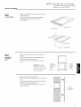
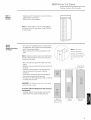
True Flush Installation
Semi-Flush Installation
In a flush installation,
These refrigerators
can also be installed
the refrigerator
doors
semi-flush
will align evenly with the
front face of adjacent
cabinet
doors. The refrigerator
blends
into the surrounding
Monogram
built-in
refrigerators
cabinetry.
can be installed
flush
frame around the opening.
Side Panel Requirements:
• Side panels are not required
with typical 24-3/4" deep cabinetry.
refrigerator
When installed
semi-flush,
the case trim will conceal
slight gaps around the enclosure.
project forward
approximately
face of surrounding
The refrigerator
will
3/4" beyond the front
situation,
through the use of
one or more trim kits. See trim kit descriptions
• Side panels are required
refrigerator
and
Product
Dimensions
and
options on page 5.
To accomplish
• The electrical
the sides of the
on the type of
an attractive installation,
1. Determine
the need for side panels.
2. Determine
side panel thickness.
• To achieve a flush fit the finished cutout width must
be at least 36" wide.
• A semi-flush installation
cutout width.
whenever
being made.
manufacturer.
dimensions.
Cutout
or between
are exposed.
3. Order matching
Enclosure
the
a wide range of appear-
ance options can be accomplished
appearance
whenever
into an enclosure
pantry and oven cabinets.
installation
In any installation
is installed
• Side panel sizes vary depending
cabinetry.
into an enclosure
using the minimum cutout
width. The case trim creates a
requires
you must:
side panels from the cabinet
Be sure to provide the exact
_Finished
Width
WallView
35-1/2" min. finished
and water locations
must be located as
shown for either type of installation.
83" Min
84-1/2"Max
841/2"max
83 1/4" min
Finished
Opening
--24 3/4"Total
Depth
74"FromFloor
to Bottom
d Electrical
31/2"
*36" Min. for a flush installation
35-1/2" Min. for a semi-flush
Note: Additional
installation
cutout width may be required when
side panels are used. Add side panel thickness
finished cutout to calculate
installation
examples
rough-in
on the following
width. See
page.
to the
Design Information
36" Built-In
Installation
Refrigerators
Examples
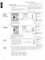
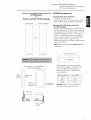
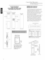
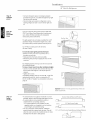
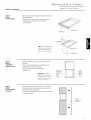
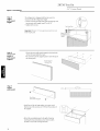
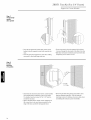
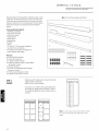
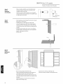
Side panels are required whenever the sides of the refrigerator will be exposed.
Therefore, the rough-in dimensions must allow for side panel
thickness. In both a flush and semi-flush installation, the
finished dimension, (the width of the opening after side panels
are installed), must accommodate the full width of the
refrigerator.
1/2" to 3/4" side panels are normally set into place and
fastened to adjacent cabinetry or to the back wall before
rolling the refrigerator into the opening.
See page 14for side panel sizes.
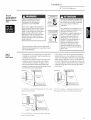
Installa
Flush and Semi-Flush
tion
Between
Base
Wall
Installations
&
Cabinets
cRefrigerator_
Side Panels
1/4" Thick _J
[_
Finished Dim. _35q/2'_
Roughedqn Dim.,
36'_
Note: 1/4" thick side panels can be
inserted into the case trim, making the
rough-in the same as the outside trim
width, 36".
Cabinet
1/4" Side Panels. Insert end of
side panel into trim
I
Flush and Semi-Flush
Installation
At
Installations
End-of-Run
l lJ2"Thick
II I
36"_
Finished Dim.
3T'_
Rough-In Dim.
Reffigerator_
Cabinet_
_ Refrigerator door _
/
Note: 1/2" thick side panels shown. Side panels can
be any thickness. Add side panel thickness to outside
trim width (36") to calculate the rough-in dimension.
The leading (front) edge must be finished to match
surrounding cabinetry.
Frameless
Cabinets
Accessory
Panel Kits
Side panels, 1/2" minimum thickness are
required when using frameless cabinets.
The side panel acts as a spacer between the
cabinet and the case trim and prevents
interference with cabinet door swing. The
leading (front) edge must be finished to
match surrounding cabinetry.
Cabinet
1/2" To 3/4" Side Panels.Leading
EdgeFlush With Cabinet
1/2" To 3/4" Side Panels.Leading
EdgeFlush With Cabinet
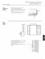
Field installed door and grille panels are required. The factory
installed trim will accept accessory panel kits. White or black
Lexan k and stainless steel kits are available. Panels are cutto
size and ready to install. These panel kits must be ordered
separately.
Model
Black
White
Stainless
ZlS36N
ZWBP36
ZWWP36
ZWSP36
ZWWP36D
ZWSP36D
ZlSW36D
ZlSB36D
ZWBP36D
ZWSP36D
A wide range of custom appearance options can be created
with optional custom trim kits. See the opposite page for
examples and trim kit descriptions.
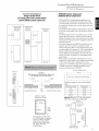
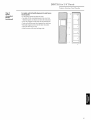
Design
Information
36"
Advance
These refrigerators
planning
exterior
decorator
appearance
options
are designed
to be customized
door and grille panels. Field installed
with
custom
door and grille panels are required.
Factory installed
trim accommodates
panels, Lexan (R_
or stainless
Built-In
Refrigerator
You should:
1. Select the appearance
option.
2. Order the trim kit(s) for that option.
1/4" thick custom
steel panel kits.
3. Order the custom door and grille panels from the
cabinet manufacturer. The exact dimension for each
Appearance options are accomplished through the
use of one or more trim kits. Kits must be ordered
trim kit application is provided in this booklet. Find
and pull out the page for your application and fax or
send it to the cabinet manufacturer. The cabinet
separately.
manufacturer
Door and grille panel sizes vary to accommodate
being used. Sizes are provided
the kit
in this booklet.
must have this information
struct the panels accurately.
4. Determine the final installation
matching
situation
to conand order
side panels.
3/4" thick custom panels-Without trim kits
A raised panel design, screwed or glued to a 1/4" thick
backing can be used. See pages 7 and 11 for panel
sizes and clearances.
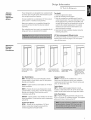
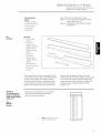
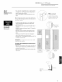
Appearance
Examples
Trim kit
Descriptions
J
1/4"and 3/4" panels with
standard handles. No trim
kits required.
Door Handle
1/4"Custom panels with
custom handles. Trim Kit
ZKHt.
1/4" Custom panels with
Tubular Stainless Steel
handles. Trim Kit ZKHSS1.
Options
ZKH1 - Provides the necessary
framework
to install
custom handles, of your choice, onto 1/4" thick panels.
(Handles not included.)
ZKHSS1 - Tubular stainless
steel handles for 1/4" thick
panel installations.
ZKH]I - Provides the necessary
framework
to install
custom handles, of your choice, onto 3/4" thick panels.
(Handles not included.) This kit must be used in
combination
with ZKT36.
ZKHTSS1 - Tubular stainless
panel installations.
with ZKT36.
steel handles for 3/4" thick
This kit must be used in combination
Custom Panel Options
ZKT36 - Provides for the installation
trimless
of 3/4" thick
custom door and grille panels with the
standard (supplied)
full length handle.
3/4" Custom panels with
custom handles. Trim kits
ZKT35 & ZKHT1.
Dispenser Options
ZWCD1 - Provides for the installation
collar trim on the dispenser
3/4" Custom panels with
Tubular Stainless Steel
handles and custem
dispenser collar. Trim
Kits ZKHTSS1, ZKT35 &
ZWCD1.
of a custom
and for one continuous
custom panel on the freezer door. This kit can be used
alone, or with all other kits.
Toekick Option
ZWT1 - White toekick (supplied toekick is black).
Includes a white toekick to fit 36, 42, 48"side-by-side
models and 36" bottom mount and single door models.
Grille Panel Options
ZG2- Provides 1/4" grille panel frame side pieces for
83",83-1/2"and 84-1/2"installation heights. The supplied
grille panel frame is factory set for 84".
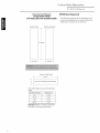
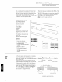
Custom
Panel
Dimensions
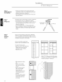
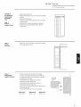
36" BzHlt-ln Refrigerator
ZIS36N
Front View
(not to scale)
Side View
not to scale
--24
3/4"--
--35"
--36"
(Non-dispenser)
Case Width/
Overall
Design
Width
Information
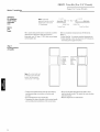
Cutout dimensions,
12 1/4" max
10-3/4" rrfin
determined
clearances
and side panel sizes are
by the many installation
options
Side panels must be used whenever
refrigerator
will be exposed.
when refrigerator
between
is installed
Side panels are not required
into an enclosure
pantry and oven cabinets.
panels, 1/2" minimum thickness,
FRAMELESS CABINETS.
84 1/2" max
83" min
• Field installed
• A custom toekick
are required
when using
The door panels and grille panel
the kit being used.
can be installed
to match or comple-
ment the surrounding
cabinetry.
toekick as a template
and water lines.
to cut out notches
Optional
or
IMPORTANT-Side
custom panels, Lexan ® or stainless steel
panels are required.
sizes vary to accommodate
72 1/4"
available.
the sides of the
Use the supplied
around hinges
Kits:
ZWBP36: Black Lexan ® Panel Kit (no trim kit required).
ZWWP36: White
Lexan C"_'
Panel Kit (no trim kit required).
ZWSP36: Stainless Steel Panel Kit (no trim kit required).
ZKHI: For installation
J
of a custom handle on 1/4" panels.
ZKT36: For installation
ZKHTI: For installation
4 _
of 3/4" custom panels.
of a custom handle on 3/4"
panels. (This kit must be used in combination
ZKT36.)
*Finished Width
Wall View
(not to Scale)
with
• ZKHSSI: Tubular Stainless Steel handles on 1/4" panels.
• ZKHTSSI: Tubular Stainless Steel handles on 3/4"
panels. (This kit must be used in combination
ZKT36.)
with
• ZG2: 1/4" grille panel frame side pieces for 83", 83-112"
84 112" max
83-114" min
Finished
Opening
Locate Grounded
Electrical outlet
Within Solid
Area Above
and 84-1/2" installation
A12
• ZWTI: White toekick
3t8"-
heights. Factory set height is 84".
(supplied toekick
Includes a white toekick
74" From
Floor to
Bottom of
Electrical Area
models and 36" bottom mount and single door models.
Additional
Specifications
• A 115 volt 60 Hz., 15 or 20 amp power supply is required.
An individual
Locate Water
Supply Within
the Shaded
is black).
to fit 36, 42, 48" side-by-side
properly
circuit breaker
grounded
is recommended.
branch circuit
or
Install a properly
grounded 3-prong electrical receptacle recessed into
the back wall. Electrical must be located on rear wall.
3 1/2"
• Water line can enter opening through
the floor or back
wall. The water line should be 1/4" O.D. copper tubing
between the cold water line and water connection
1/2"
--_-
*36" Min. for a flush installation
into an enclosure.
"35-1/2" Min. for a semi-flush
installation
into an enclosure.
Note: Additional
cutout width may be required when side panels
used. Add side panel thickness to the finished cutout to calculate
rough-in width. See installation
examples on page 4.
location,
long enough to extend to the front of the
refrigerator. Installation of an easily accessible
valve in the water line is recommended.
are
shut off
Clearances
If the refrigerator
is to be installed in a corner:
• A 4" min. clearance between the case trim and
adjacent
wall on both sides of the refrigerator
assure a 90 ° door opening
A 10" clearance
of pans.
is required
will
and access to all drawers.
on both sides for removal
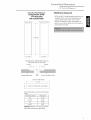
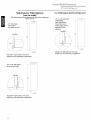
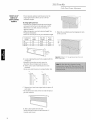
Custom
Panel
Dimensions
36 " Built-In
Custom Door Panel Dimensions Using Standard Trim
ZIS36N
1/4" thick panels
or
Panels secured to 1/4" thick backing
Standard
Freezer Panel
Fresh
Refrigerator
(non-dispenser)
Trim
with
1/4" Panels
• 1/4" Panels: Cut panels to size.
• Custom handles with 1/4" door panels require Trim Kit
ZKH1 (or ZKHSS1 for tubular-stainless
steel handles).
Food Panel
Standard
Trim
1/4" thick
backing
• Applying
with
Panels
secured
to
a raised panel design to a 1/4" thick backing
(screwed
or glued): Cut 1/4" panels to size, fabricate
raised panel to permit clearances
handle side for fingertip
the
of at least 2" from the
clearance
of the standard
handle, 1-1/4" from the hinge side to avoid striking
adjacent
67 7/8"
cabinetry
and 5/16" from the top and bottom
edges to allow for the trim flange then install.
• Countertops
adjacent
to refrigerator
installation
should
be mitered 45° degrees.
Note:
ZKHT1 custom handle kit cannot be used in this
configuration.
-15
1/4"--
--19
Custom Grille Panel
1/4"--
35"
1t4" Thick Panel
9"
.b
The grille panel frame is factory
Raised
Panel on 1/4" Thick
Backing
for 84" installation
assembled
height. If installation
height
varies, order ZG2 trim kit which provides
optional side trim pieces. Cut grille panel to
sizes shown below.
1/4" --_
Thick
BacMnc[
I I
[
bApp earance
[ Pand
2" Clearance
handle side
Handle
Installation Height
Panel Height
83"
8"
83-1/2"
8-1/2"
84-1/2"
9-1/2"
Important: Maintain 1-1/2" rain, gap between
top of doors and bottom of panel frame.
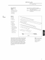
Custom
Panel
Dimensions
36" Built-In
Custom Door Panel Dimensions
ZIS36N
Refrigerator
(non-dispenser)
Using Trim Kit ZKT36
314"thick panel with standard handle
• The ZKT36 trim kit provides for the installation of 3/4"
custom door and grille panels, using the standard fulllength handle.
Freezer
Panel
Fresh Food
Panel
67 15/16"
_19
_15 1t16%
1/16",
Custom GriHHePaneH
35 1t2"
Over 1/4" Thick (3/4" max) Panel
Grille Panel height can vary to fill installation
height.
Installation Height
83"
Dimension A
8-1/4"
83-1/2"
8-3/4"
84"
9-1/4"
84-1/2"
9-3/4"
Important.. Maintain
1-1/2" min, gap between
top of doors and bottom of grille panel,
]
Cut panels to size and install.
Custom
Panel
Dimensions
36" Built-In
Custom Door Panel Dimensions
ZIS36N
Using Trim Kits ZKT36
3/4" thick panel
Panel
Fresh Food
(non-dispenser)
• ZKT36 and ZKHT1 installed together provides for the
installation of 3/4" custom door and grille panels,
with custom handle
Freezer
Refrigerator
Panel
using a custom handle, of your choice. Order
ZKHTSS1 for tubular stainless-steel
handles. Cut
panels to size, rout the handle side of the panels as
shown below and install.
67 15/16"
_19 5/16"_
Rout panels to specification
below
the handHe side of each paneH
1 13t16:'
on
1 13t16"
/'
Freezer Door Face
1/4"
max
\
Fresh Food Door Face
Custom GriHHePaneH
35 1/2"
A
Over 1/4" Thick (3/4" max) PaneH
Grille Panel height can vary to fill installation
height.
Installation Height
Dimension A
83"
8-1/4"
83-112"
8-314"
84"
9-1/4"
84-112"
9-314"
Important: Maintain
1-1/2" min. gap between
top of doors and bottom of grille panel.
/
Custom
Panel
Dimensions
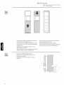
36" BzHlt-ln Refrigerator
ZISW36D
ZISB36D
Front View
(not to scale)
Side View
not to scale
--24
3/4"_
Design
35" Case Width_
6" Overall
(white
(black
Information
Cutout dimensions,
Width_
dispenser)
dispenser)
determined
clearances
panels must be used whenever
12 1/4" max
10-3/4" rnin
and side panel sizes are
by the many installation
options available.
will be exposed. Side panels are not required
refrigerator
is installed
and oven cabinets.
• Field installed
into an enclosure
IMPORTANT-Side
thick, are required
Custom door panels and grille panel
• A custom toekick
Optional
the kit being used.
can be installed
ment the surrounding
72 1/4"
pantry
panels, 1/2" min.
for FRAMELESS CABINETS.
sizes vary to accommodate
a template
when
or between
custom panels, Lexan C_'or stainless steel
panels are required.
84 1/2" max
83" rrfin
Side
the sides of the refrigerator
cabinetry.
to match or compleUse supplied toekick
as
to cut notches for hinges and water lines.
Kits:
ZWBP36D: Black Lexan ® Panel Kit (no trim kit required).
ZWWP36D:
White Lexan '_ Panel Kit (no trim kit required).
ZWSP36D: Stainless
Steel Panel Kit (no trim kit required).
ZKHI: For installation
of custom
ZKT36: For installation
_7
handles on 1/4" panels.
of 3/4" custom panels.
ZKHTI: For installation of custom handles on 314" panels.
(This kit must be used in combination with ZKT36.)
• ZWCDI: For installation of a custom collar trim on the
L
4"
dispenser for one continuous
on the freezer door.
*Finished Width
Wall View
(not to Scale)
custom panel
• ZKHSSI: Tubular Stainless Steel handles on 1/4' panels.
• ZKHTSSI: Tubular Stainless Steel handles on 3/4" panels.
(This kit must be used in combination with ZKT36.)
• ZG2: 1/4" grille panel frame side pieces for 83", 83-1/2" and
84-1/2" installation
84 1/2" max
83-1/4" rnin
Finished
Opening
Locate Grounded
Electrical outlet
Within Solid
Area Above
heights. Factory set height is 84".
• ZWTI: White toekick
(supplied toekick
_12 3/8"
74" From
Floor to
Bottom of
Electrical Area
Additional
Specifications
• A 115 volt 60 Hz., 15 or 20 amp power supply is required.
An individual
properly
grounded
• Water line can enter opening through
3 1/2"
location,
the floor or back
long enough to extend to the front of the
refrigerator. Installation of an easily accessible
valve in the water line is recommended.
into an enclosure.
installation
into an enclosure.
may be required
when
side panels
to the finished
cutout
to calculate
examples
on page 4.
shut off
Clearances
If the refrigerator
are
is to be installed
• A 4" rain. clearance
between
in a corner:
the case trim and adjacent
wall on both sides of the refrigerator
door opening
is required
10
or circuit
wall. The water line should be 1/4" O.D. copper tubing
between the cold water line and water connection
3 1/2"
cutout
width
panel thickness
See installation
branch circuit
Install a properly grounded
3-prong electrical receptacle recessed into the back wall.
Electrical must be located on rear wall.
Locate Water
Supply Within
the Shaded
Note: Additional
used. Add side
rough-in
width.
models and
36" bottom mount and single door models.
breaker is recommended.
*36" Min. for a flush
installation
"35-1/2"
Min. for a semi-flush
is black). Includes
a white toekick to fit 36, 42, 48" side-by-side
will assure a 90°
and access to all drawers.
A 10" clearance
on both sides for removal of pans.
Custom
Panel
Dimensions
36" Built-In
Custom Door Panel Dimensions Using Standard Trim
1/4" thick panels
or
Panels secured to 1/4" thick backing
ZISLIV36D
ZISB36D
(white
(black
Refrigerator
dispenser)
dispenser)
mm
Standard
Trim
with
1/4" Panels
• 1/4" Panels: Cut panels to size.
• Custom handles with 1/4" door panels require
Freezer Panel
Standard
Dispenser
ZKH1. When using ZKH1 with the standard
Freezer Panel
Custom
Dispenser
Fresh Food
Panel
Trim Kit
dispenser
trim, the length of the custom handle, top to bottom
cannot exceed 11-3/4".
• Tubular stainless steel handle kit, ZKHSS1.
• Custom collar dispenser
trim with 1/4" door panels
require trim kit ZWCD1,
Standard
1/4"
67 7/8"
_1
_2
Trim
thick
with
Panels
secured
to
backing
• Applying a raised panel design to a 1/4" thick backing
(screwed or glued): Cut 1/4" panels to size, fabricate
9t16"
the raised panel to permit clearances
from the handle side for fingertip
standard
36 7/8"
of at least 2"
clearance
of the
handle, 1-1/4" from the hinge side to avoid
striking adjacent
cabinetry
and 5/16" from the top and
bottom edges to allow for the trim flange, then install.
• Countertops
adjacent
to refrigerator
installation
should be mitered 45° degrees.
_15 1/4 4
_19
1/4"
Note: ZWCD1 custom collar dispenser trim and
ZKHT1 custom handle kits cannot be used in this
configuration.
Custom Grille Panel
35"
Raised Panel on 1/4" Thick Backing
Using Standard
Handles
1/4" Thick Panel
9"
The grille panel frame is factory assembled
1/4"--_
Thick
for 84" installation
II
height. If installation
varies, order ZG2 trim kit for optional
pAppearance
height
side trim
)ieces. Cut grille panel to sizes shown below.
Backing
I
Installation Height
I Panei
2" Clearance
handle side
Panel Height
83"
8"
83-1/2"
8-1/2"
84-1/2"
9-1/2"
Important: Maintain
1-1/2" min, gap between
top of doors and bottom of panel frame.
Custom
Handle
Dispenser
Cutout
12 5/16"
The Cutout is 9 7/16" wide
by 12 5/16" high,
11
H
Custom
Panel
Dimensions
36" Built-In
Custom Door Panel Dimensions
ZISW36D
ZISB36D
Using Trim Kit ZKT36
(white
(black
Refrigerator
dispenser)
dispenser)
3/4" thick panel with standard handle
and/or ZWCD1 custom collar trim
• The ZKT36 trim kit provides for the installation
of 3/4"
custom door and grille panels, using the standard fulllength handle. Cut panels to size and install.
• For standard dispenser trim: Cut panels to size, rout the
Freezer Panel
Standard
Dispenser
Freezer Panel
Custom
Dispenser
bottom of the upper freezer panel and the top of the
Fresh Food
Panel
lower freezer panel to allow placement
brackets and install (see detail A).
of support
• For custom dispenser trim ZWCD1 kit must be used: Cut
panels to size, refer to detail B for dispenser cutout
routing instructions
16 11_"_
and install. When a raised panel
design is used, a custom middle rail is required. A
14-1/2" wide middle rail must be used because the
custom collar trim must be located
within the raised
portion of the panel. This area must be 3/4" thick. See
detail C for raised panel design requirements.
Custom Grille Panel
35 1t2"
Over 114" Thick (3/4" max) Panel
-- 19 1t16"Grille Panel height can vary to fill installation
height.
DetailA
Upper
Freezer
Panel
Installation Height
83"
Dimension A
8-1/4"
83-1/2"
8-3/4"
84"
9-1/4"
84-1/2"
9-3/4"
Detail B Custom
Dispenser Cutout
Important.. Maintain
1-1/2" min. gap between
top of doors and bottom of grille panel.
1 "
.J.
_L9
1"
7/16"_
12 5116"
7/8"
Wide
Rout
Panel
Face
Lower
Freezer
Panel
The Cutout is 9 7/16" wide
by 12 5116" high. 3t4" panels
must be routed on all four
sides of the cutout. Rout
the back side of the panel
1t4" deep. 7t8" wide
(shaded area).
Detail C
Raised Panel Design
.....
_2-3/16" Stiles
RightSide
Hole is Cut
After Door
Fabrication ,
14 !/2"
Wide
Middle
Rail
--Handle
*CustomStiles and
MiddleRail Required
12
SectionAA
Custom
Panel
Dimensions
36" Built-In
Custom Door Panel Dimensions
ZISW36D
ZISB36D
Using Trim Kit ZKT36
(white
(black
Refrigerator
dispenser)
dispenser)
314" thick panel with custom handle
and/or ZWCD1 custom collar trim
• ZKT36 and ZKHT1 installed
installation
of 3/4" custom
together
provides for the
door and grille panels, using
a custom handle of your choice. Cut panels to size, rout
Freezer Pand
Standard
Dispenser
the handle side of the panels as shown below and install
Freezer Pand
Custom
Dispenser
(see detail B).
Fresh Food
Pand
• For ZKHTSS1 tubular
stainless steel handle kit, cut panels
to size and rout the handle side of the panels as shown in
detail B.
• For standard dispenser
trim: Cut panels to size, rout the
handle side of the panels as shown in detail B, rout the
16 1111_6"
_
bottom of the upper freezer panel and the top of the lower
freezer panel to allow placement
• For custom dispenser
i"
r ........
_1
_2
(see
trim ZWCD1 kit must be used: Cut
panels to size, refer to detail C for dispenser
9116"
routing instructions.
i
i
of support brackets
detail A) and install.
67 15/16"
I
cutout
When a raised panel design is used,
a custom middle rail is required. A 14-1/2" wide middle rail
must be used because the custom collar trim must be
located within the raised portion of the panel. This area
must be 3/4" thick. See detail D for raised panel design
requirements.
• When using the standard
L15 5/16",
/
full-width
dispenser
trim, the
length of the custom handle, top to bottom cannot exceed
11-3/4". Locate the handle a minimum of 3/4" and a
19 5t16"=
maximum of 1-1/2" from the edge of the panel. There are
no length restrictions
on handles for models using a
custom collar dispenser
trim (ZWCD1).
Custom
DetailA
Upper
Freezer
Panel
Detail
Rout
B
panels to specification
the handle side of each
Grille
Panel
35 1t2"
below
panel
on
A
Over 114" Thick
(314" max)
Panel
1 13116"
Grille Panel height can vary to fill installation
height.
1 "
.J
1"
Panel
Face
f
Freezer Door Face
1t4"
max
x
Fresh Food Door Face
DetMIC Custom
Dispenser
Cutout
Installation Height
83"
Dimension A
8-1/4"
83-1/2"
8-3/4"
84"
9-1/4"
84-1/2"
9-3/4"
Important:
Maintain
top of doors
Lower
Freezer
Panel
_19
7/16"+
12 5116"
*3" Stiles
Left Side
7/8"
Wide
Rout
is 9 7/16" wide
by 12 5116" high. 3/4" panels
must be routed on all four
sides of the cutout. Rout
the back side of the panel
1/4" deep. 7/8" wide
(shaded area).
min. gap between
_2-3/161' Stiles
Right Side
A
Hole is Cut
After Door
__
The Cutout
1-1/2"
and bottom of grille panel.
Detail D
Raised Panel Design
Fabrication
_[
141/2"
Wide
Middle
Rail
A
-Handle
Side
*Custom Stiles and
Middle Rail Required
Section AA
13
Custom
Panel
36
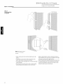
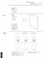
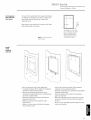
Side Panel or Filler Options
For All
Dimensions
" Built-In
Monogram
Refriserator
Built.In
Refrigerators
(not to scale)
Side panels must be used whenever the sides of the refrigerator
will be exposed.
-23
9/16"-
1/2" to 3/4" Side Panels
1/4" Side Panels
Front. The front or
Insert end of
leading edge, must be
finished to match
side panel into trim.
_24
3/4"_
Leading Edge
Flush with Cabinet
cabinetry.
Top View
84"
Top View
84"
\
\
3 3/4"
2 9/16"
Standard
4" high toekick or trim to fit.
Height may vary depending
Standard
4" high toekick or trim to fit.
Height may vary depending
on application.
=23 5/16"_
1/2" to 3/4" Side Panels
Recessed front
edge.
TopView
84"
\
]
\\
\.
j
2 5116"
Standard
4" high toekick or trim to fit.
Height may vary depending
14
on application.
on application.
Installation
36"
Tools
• Tinsnips to cut banding
Required
• Stepladder
• 1-1/2" open-end
• Bucket
• Level
Refrigerator
• 7/16"open-end wrench
• #2 Phillips screwdriver
• Stubby Phillips
screwdriver
• Appliance Hand Truck
• Tubing cutter
wrench
Built-In
• Drill and appropriate
bits
• 7/16" socket with
extension
3"
for ratchet
• Safety glasses
Hardware
Supplied
• Special velcro adhesive
• 1/4-1/4 union with nuts
strips for 1/4" side
• 1/4" panel foam spacers
panels
Materials
Required
Flooring
• Water shut-off valve (optional but recommended)
• Custom panels for fresh food, freezer compartments,
grille panel
• Side panels
• Hardware for side panel installation.
• 36"long 2x4 for Anti-Tip support
For proper installation, this refrigerator must be placed
on a level surface of hard material that is at the same
Note: Protect the finish of the flooring.
height as the rest of the flooring.
refrigerator
This surface
section of the cardboard
should be
Cut a large
carton and place under the
where you are working.
strong enough to support a fully loaded refrigerator.
Grounding
the
IMPORTANT - (Please read carefully)
Refrigerator
FORPERSONALSAFETY,THIS APPLIANCE MUST BE
PROPERLYGROUNDED.
Attaching
the adapter ground terminal
to a wall
outlet cover screw does not ground the appliance
unless the cover screw is metal, and not insulated,
The power cord of this appliance
three-prong
(grounding)
standard three-prong
minimize the possibility
is equipped
with a
and the wall outlet is grounded through the house
wiring. You should have the circuit checked by a
plug which mates with a
(grounding)
wall receptacle
of electric
to
qualified
electrician
shock hazard from
properly
grounded.
to make sure the outlet is
this appliance.
When disconnecting
Have the wall outlet and circuit
electrician
checked
by a qualified
always
to make sure the outlet is properly
with repeated
a standard
is your personal
replaced
2-prong wall outlet is encountered,
responsibility
and obligation
with a properly grounded
to have it
3-prong wall outlet.
Use of Adapterplug
f
Because of potential hazards under certain conditions,
we strongly recommend against use of an adapter plug.
However, if you still elect to use an adapter, where
local codes permit, a TEMPORARYCONNECTION,may
be made to a properly grounded 2-prong wall outlet by
use of a UL listed adapter available at most hardware
stores.
must be aligned with the
larger slot in the wall outlet to provide
the connection
proper polarity
use.
it
DO NOT,UNDERANY
CIRCUMSTANCES,CUT
OR REMOVETHE THIRD
(GROUND)PRONG
FROMTHE POWERCORD.
The larger slot in the adapter
in place with one hand and
pulling the power cord with the other hand. If this is not
done, the adapter ground terminal is very likely to break
grounded.
Where
the power cord from the adapter,
hold the adapter
in
Should the adapter ground terminal break, DO NOT USE
the appliance until a proper ground has again been
established.
Use of Extension Cords
Because of potential safety hazards under certain
conditions, we strongly recommend against the use of
an extension cord. However, if you still elect to use an
extension cord, it is absolutely necessary that it be a UL
listed 3-wire grounding type appliance extension cord
having a grounding type plug and outlet and that the
electrical rating of the cord be 15 amperes (minimum)
and 120volts.
FICHED'ADAPTATION
(Fiches d'adaptation
Canada)
non
permises
au
of the power cord.
15
Installation
36"
Built_ln
Refriserator
Step
1
Remove
Packaging
Refrigerator is much heavier at the top than at the
bottom - be careful when moving. When using a
hand truck, handle from side only.
Le refrigerateur
est beaucoup plus Iourd en haut
qu'en has. II faut etre prudent Iors des
deplacements. Si un diable est utilise, il faut
soulever le refrigerateur
sur le cote seulement.
• Remove outer carton.
- Carefully
cut banding at the top and bottom.
• Slide out back corner posts (2).
• Slide carton off top of cabinet.
NOTE: IT IS NOT NECESSARY TO LAY CABINET DOWN
IN ORDER TO REMOVE SKID!
• To remove skid, remove the four 7/16" bolts and their
brackets.
• There are support blocks on the bottom of the cabinet
and door. They must be removed before sliding unit
DO NOT ATTEMPTTO ROLLUNIT OFFSKID.
off the skid or damage will occur.
• Carefully, tilt cabinet
beneath cabinet,
IL NE FAUT PAS ESSAYERDE FAIREROULERLE
REFRIGERATEUR
POURL'ENLEVERDE LAYPALETTE.
• A cold water supply is required
Step 2
Install
operation.
Water
120 p.s.i.
Line
for automatic
and slide blocks out from
slide unit off skid.
• Remove toekick from fresh food compartment
set aside for later installation.
and
icemaker
The water pressure must be between
40 and
• Route 1/4" OB copper tubing between house cold water
line and the water connection location.
Floor
• Copper tubing should be long enough to extend to the
front of the refrigerator.
bend leading
Allow enough to accommodate
into the water valve.
CopperTubingJ
Shut off the main water supply.
Turn on the nearest faucet long enough to clear the line
of water.
• Install a shut-off
valve between
the icemaker
water
valve and cold water pipe in a basement or cabinet.
The shut-off valve should be located where it will be
easily accessible.
NOTE: It is best to install the valve into a vertical
pipe. If you install the valve into a horizontal
make the connection
,Inlet End
Saddle Type
Shuto_
-Pipe Clamp
water
Packing _
Compression Nut
water pipe,
at the top or side, rather than at
the bottom, to avoid drawing
off any sediment from the
water pipe.
• Drill a 1/4" hole in the water pipe.
Outlet Valve
Ferrule
• Fasten the shut-off valve to the pipe with pipe clamp.
• Tighten the clamp screws
NOTE: Saddle type shut-off valves are included in
begins to swell. Do not over tighten.
• Place a compression nut and ferrule (sleeve) onto the
end of the tubing and connect it to the shut-off valve.
Make sure the tubing is fully inserted
ferrule
into the valve and
many water supply kits. Before purchasing,
a saddle type valve complies
codes.
make sure
with your local plumbing
is tightened.
• Turn on the main water supply and flush debris from
the line. Run about a quart of water through the tubing
into a bucket. Shut off water supply at the shut-off
valve.
16
(Sleeve)
until the sealing washer
NOTE: Commonwealth of Massachusetts
Plumbing
Codes 248CMR shall be adhered to. Saddle valves
are illegal and use is not permitted
Consult with your licensed
plumber.
in Massachusetts.
Installation
36"
Built-In
Refrigerator
Step
2.4
For Installations
With
A Reverse
Osmosis
System
Only
When connecting a GE Reverse
Osmosis Water System to your
refrigerator, the only approved
installation is with a GE RVKIT.
Lors du raccordement
au refrigerateur
du systeme GE de purification de I'eau
par osmose inverse seule I'installation
avec un ensemble GE RVKIT est
z,t.SU
Clockwise ,_, m,b
To Remove
approuvee.
If the water supply to the refrigerator
is
from a Reverse Osmosis Water System
AND the refrigerator also has a water
filter, use the refrigerator's
filter bypass
plug. Using the refrigerator's
water
filtration cartridge in conjunction with
the RO filter can result in hollow ice
cubes and slower water flow from the
Si le refrigerateur
es alimente en eau
partir d'un systeme de filtration d'eau
par osmose inversee, et si le
refrigerateur
comporte egalement un
filtre a eau, utiliser le bouchon du
circuit de derivation du filtre du
refrigerateur.
Si la cartouche de
filtration d"eau du refrigerateur
est
utilisee en conjonction avec le
systeme de filtration par osmose
inversee, on peut observer une
reduction du debit d'eau au point de
puisage, et la production de cubes de
glace creux.
Bypass
Plug
water dispenser.
If you use the bypass Plug and want a light shield
without the filter opening,
order a replacement
solid
light shield WR02X3025.
Step
3
Install
Side
Panels
• Side panels are not required
installed
into an enclosure.
installing
in an enclosure.
• Side panels are required
refrigerator
between
when the refrigerator
is
Skip this step if you are
panels to the refrigerator
whenever
the sides of the
will be exposed and when installed
frameless
cabinets.
• Side panel installation
• If you choose to use 1/4" side panels, they should be
inserted into the case trim as illustrated. Fasten the
See pages 3 and 4.
will be determined
by the
design of the side panel you have previously
• Side panels must be installed
chosen.
before setting refrigerator
with Velcro
strips (provided)
in place. See illustration
A.
• 1/2" to 3/4" side panels are normally set into place and
fastened
to adjacent
cabinetry
rolling the refrigerator
tions B and C.
or the back wall before
into the opening.
See illustra-
plumb.
Illustration A
Illustration B
1][ie_rigerator_
Cabinet'_
_
Refrigeratordoor _
Refrigeratordoo,
1/4" Side Panels Insert EndOf Side Panel Into CaseTrim, Fasten
1/2" to 3/4" Side Panels
With Velcro Strips provided,
With Cabinet front. FastenTo The BackWall Using A Cleat.
Illustration C
Leading EdgeOf Side Panel Is Flush
I
Cabinet
Ref igerator_K_
Refrigerator door
1/2" to 3/4" Side Panels
RecessedFront Edgeof Side Panel.
FastenTo Adjacent Cabinet.
17
Installation
36'"
Step
4
Roll
Refrigerator
Into
Opening
The front is supported
Level
by leveling
Refrigerator
• To level the back of the refrigerator,
nut located above the front wheels.
Step
5
Refrigerator
• Gently push refrigerator into opening with hands
against front corners The cardboard protective pad
should be beneath the refrigerator
• Roll refrigerator into the opening until it is flush with
adjacent cabinets
All models have 4-point leveling.
I
Built-In
legs, the rear is supported
by wheels.
turn the 7/16" hex
Turn to raise or
lower the refrigerator.
• For front leveling, use a 1-1/2" open-end
• Adjust carefully, the refrigerator
plumb with cabinetry,
wrench.
should be level and
and should align with toekick
height.
Step 6
Install
1/4"
Door
Panels
If you are using 3/4" thick custom panels, SKIP THIS
STEP See Custom Panel Dimensions pages for panel
sizes with ZKT36 trim kit and other kits. Refer to trim kit
installation instructions in this bookleL
If you are using the custom collar
dispenser
trim, order ZWCD1 trim kit.
[]
To install
1/4" door panels:
• Open door to 90 ° stop. Remove the
Phillips head screws from the
aluminum trim door handles.
Retain all screws.
[]
• Attach
[][][]E
2" x 2" adhesive backed foam pads
to the door. These fillers are shipped with
literature
• Slide panel into the door
trim.
• Replace door handles
and secure with original
screws.
• Again, check to be sure
unit is level and that
panels align with
cabinetry.
Doors will not
close properly
not level.
if unit is
• Check for noises caused
by incomplete
alignment
(rubbing of panels, trim
or screws).
18
package
in snack pan.
Installation
36'"
Step 7
OPTION
Secure
Built-In
Refrigerator
1
ANTI-TIP PRECAUTIONS
refrigerator
at the top
The refrigerator
is heavy at the top and must be
secured to prevent the possibility of tipping forward.
PRECAUTIONS CONTRE LES BASCULEMENTS
Le retrigerateur
est beaucoup
plus Iourd en haut et
il faut le maintenir en place pour eviter la possibilite
de son basculement vers I'avant.
To prevent the refrigerator
from tipping over, you must:
• Install a wood block, the full width of the refrigerator.
Secure the block with wood screws
least 3/4" into wall studs.
OPTION
Secure
2
refrigerator
at the sides
penetrating
Side View
at
Side View
When using 1/2" to 3/4" side panels, the front flange of
the case trim is attached
to the side panel.
TopView
• Open freezer door to access case trim.
Side
• Drill hole in case trim slightly below top hinge. Drive
screw through the trim and into the side panel.
Panel
• Follow the same procedure
Refrigerator Cabinet
-_)
on the fresh food side.
Refrigerator
Door
/
OR
If refrigerator
is installed
between cabinets with no side
panels or in a custom enclosure,
as shown.
install a spacer block
• Open freezer door to access case trim.
• Drill hole in case trim slightly
screw through
below top hinge. Drive
the trim and into the spacer block.
• Follow the same procedure
for fresh food side.
Spacer
Block
\
Refrigerator Cabinet\
T
Top View
Refrigerator
Doo
_Spacer+
Step 8
Connect
Water
Supply
1111
\
Check to be sure that refrigerator power cord is not
plugged into the wall outlet.
• Locate and bring copper tubing to the front of the
cabinet.
• Turn the water on to flush debris from line, run about
a quart of water through tubing into a bucket, then
shut-off water.
• Slip a 1/4-1/4 union nut (provided)
over both ends of
the copper tubing at the right front leg of then
refrigerator
and couple the lines.
• Turn on the water to check for leaks.
19
Installation
36"
Step
9
Connect
power
• Connect refrigerator
grounded
Built-In
Refrigerator
power cord plug to properly
receptacle,
accessible
through
the top right
side of the grille opening.
• Check to make sure power to refrigerator
opening
refrigerator
is on by
door to see if interior lights are
/
/
on.
Step
Mount
10
Top Grille
Panel
If you are using 3/4" thick custom panels, SKIP THIS
STEP See Custom Panel Dimensions for grille panel
sizes. Order ZKT36kit and follow the installation
instructions packed with the kiL
TopCaseTrim
The grille panel frame is factory assembled
installation
height. If installation
ZG2 trim kit which provides
for an 84"
height varies, order
optional
Raise
Installation
Height
side trim pieces.
Cut 1/4" thick custom panel to fit the frame,
35" wide, 9"deep.
To insert decorative grille panel into the frame:
• Remove screws (2 on each top corner) and "L"
brackets on each side.
• Slide panel into the frame and reassemble.
• Mount the grille panel by dropping
case trim.
For shipping purposes,
84" installation
into slots on the
the top case trim is secured
at
height.
To raise or lower case trim to other installation
heights:
• Loosen 2 screws on both sides and raise the top case
trim to meet soffit height or to the top of adjacent
cabinets.
• Tighten all 4 screws.
If installation
optional
height is more or less than 84", order ZG2
grille panel kit which accommodates
83-1/2" and 84-1/2" heights. See installation
1-1/2"
rnin.
gap
83",
instructions
page 26.
Important Maintain 1-1/2" rain. gap between top of doors and
bottom of panel frame.
Step
11
Install
Toekick
• A standard toekick is supplied. Install with 2 screws
provided, adjust to desired height and tighten screws.
• A custom toekick can be installed to match or
complement
the surrounding
- If a custom toekick
supplied toekick
StandardToekick(Packedwith Product)
cabinetry.
is to be installed,
as a template
use the
1/4" ThickCustomToekick
to cut out notches
around hinges and waterline tubing.
• For 1/2" to 3/4" thick custom toekicks, additional
material should be removed and cut away. This will
allow the water and electrical umbilical tube to rotate
1/2" to 3/4" Thick Custom Toekick Remove Additional Material
smoothly when the door is fully opened.
16"
2O
ZKH1 Trim
Kit (For
Support
Tools and materials
These instructions
required:
Option 1--For
• #2
1/4"
for Custom
Panels)
H;_ndles
are divided into 2 options:
non-dispenser
and dispenser
models
using custom collar trim.
Phillips
screwdriver
Option 2--For dispenser model using the standard
full-width trim.
• Drill and appropriate bits
• Custom door panels
• Custom handles
• Safety glasses
Parts List:
A. Freshfood door
extrusion
B, Freezerdoor
extrusionfor non-
Kit
contents
/
dispensermodeland
dispensermodel
using customcollar,
(Option1)
C, Freezerdoor
extrusionfor
dispensermodel
using full-width trim.
(Option2)
D, Handlebracketfor
dispensermodelusing
full-widthtrim.
(Option2)
This kit provides the necessary
For
1
model
model
collar
or
dispenser
using
trim
dispenser
and non-dispenser
tor door panels. (Handles not included.) The door
extrusions and bracket allow custom handles to be
to a non-dispenser
secured
a dispenser
to the door structure,
rather than the door
all the necessary
• Open doors to 90°. Remove the screws
non-dispenser
to install
instructions
panels. This kit contains
OPTION
framework
custom handles, of your choice, onto 1/4" thick decora-
parts for
models. Follow the
for Option 1 when applying custom handles
model or dispenser
custom collar trim. Follow instructions
dispenser
model using
in Option 2 for
model using the standard full-width
trim.
from the
full-length aluminum handles of both doors.
• Retain screws, discard handles.
custom
Step
1
Remove
handles
Note: If a customcollar is to be
used,order ZWCD1Trim Kit.
21
ZKH1
Trim
Kit (For
Support
Option
for
1/4" Panels)
Custom
H;_nctles
I Installation
Step
2
Locate
position
of handles
_.../Door Extrusion
Min.
lq/2" Max
/
Note: Handlemust be located
3/4" to 1ol/2" from edgeof
extrusion.
• Slide custom
frames.
panels into fresh food and freezer door
the centerlines
• Temporarily secure the new door extrusions
doors. Use at least 2 screws on each door.
• The handles must be located
of the extrusion.
• Determine
the desired
and carefully
22
• Again, with both doors closed, check the location of
to the
:3/4"to 1-1/2" from the edge
• Drill 1/16" pilot hole through
the aluminum
extrusion.
of the screw holes.
to the edge
door.
the panel until it starts into
This will mark the matching
location for drilling the clearance
location of the custom handles
mark centerlines
to be sure they are parallel
of the door, and level with opposite
hole when assem-
bling the handle, panel and extrusion.
ZKH1
Trim
Kit (For
Support
Option
for
1/4"
Custom
Panels)
H;_ndles
1 Installation
Step 3
Assemble
extrusion
handle
panel,
and
Screw
_Extrusion
Decorator_
DoorPanel
Decorator
Door _/
Panel
/
I
3/4"Min.
1-1/2"Max,
Handle_l;
/
Door Handle-__
• Remove the door extrusions
and door panels.
• Drill 1/16" pilot hole through extrusion.
• Drill clearance
• Assemble
handle.
• Install screw(s)
extrusion,
holes through the panel and extrusion.
the door panel, extrusion
long enough to pass through
• Re-install
the
door panel and into the handle.
• Slide the assembly
extrusion
and custom
into the door frame until the new
fits firmly against the steel door.
original
screws
into the door extrusion.
23
ZKH1
Trim
Kit (For
Support
OPTION
For
2
dispenser
using
trim
full-width
Step
1
Remove
handles
Step 2
Remove
trim
• Open door to 90°. Remove the screws
model
for
1/4"
Custom
Panels)
H;_ndles
from the
full-length aluminum handle of the freezer door.
• Retain screws, discard handle.
Remove door panel trim above and below dispenser.
Lift off dispenser
trim. Retain screws
and trim.
/
/
/
Remove
Trim
T
_-
,r
I
I
I
/
/
Remove
Dispenser Trim
/
Step
3
Locate
position
of handle
• Position the handle bracket
matching existing
bracket. Temporary
secure with screws.
• Re-install dispenser trim, temporarily.
• Determine the desired location of the custom handle
and carefully
mark centerlines
• Drill 1/16" pilot hole
through the trim until it
starts into the handle
bracket. This will mark
the matching
drilling
location for
a clearance
hole
when assembling the
handle, bracket and
dispenser
trim.
• Remove dispenser
and bracket.
24
onto the steel door by
screw holes on the door and
trim
of the screw holes.
-Temporarily
Secure
Handle
Bracket
With
Screws
Temporaril}
Secure
Dispenser<
Trim
With
Screws
ZKH1 Trim Kit (For 1/4" Panels)
Support
Option
for Custom
H;_ndles
2 Installation
• Drill clearance
Step 4
Install
custom
the dispenser
handle
• Install screw(s)
handle bracket,
custom handle.
holes through the handle bracket
and
trim.
long enough to pass through
dispenser
the
trim and into the
Dispenser
Trim
HandleBracket
/
Note: The customhandle must
I
be installed against tile handle
bracket.Tile customhandle
cannot exceed11-3/4" length.
_..._
ii
_
• Mount assembled
the door
Step
5
Mount
assembled
dispenser
trim
dispenser
DispenserTrim
CustomHandle
trim with handle onto
• Drive 2 screws through the top and bottom of the
handle bracket into the steel door.
• Re-install
dispenser
3 screws
at top and bottom of
trim.
Important: The ilandle
bracket must be securedto ti_e
steel door. if it is not secured
Secure
Assembled
Dispenser
Trim
•
|
|
|
Secure
Handle
Bracket
With
Screws
With
Screws
properly, the dispensertrim will
pull away from the door.
Step
6
Install
custom
extrusion
handle
• Slide decorator panels into the trim, top and bottom.
• Slide freezer door extrusion in between panels and
steel door. Secure with screws.
• To install fresh food handle follow the same procedure
¢,
as shown in Option 1.
Freezer
_Handle
Side
Extrusion
i_i!i_ii_ii_ii_ii_ii_ii_ii_ii_ii_ii_ii_ii_ii_ii_
25
ZG2 Trim
Kit
GHlle
FOR83",83-1/2"
AND 84-1/2"
INSTALLATION
HEIGHTS
• This kit provides optional
original
Panel
Frame
Ac[j't/stment
side trim pieces for the
grille frame to fit 83", 83-1/2" or 84-1/2"
installation
heights.
To change grille panel size:
• Determine the installation height by measuring the
enclosure from the floor to the underside of soffit.
When there is no soffit, measure to the top of
adjacent
cabinets.
• Adjust refrigerator case trim to desired
Production Installation.
height. See
• Select the side trim pieces for your installation
Installation
Height
83"
83-1/2"
84-1/2"
Panel
Width
35"
35"
35"
A. Locate original
Panel
Height
8"
8-1/2"
9-1/2"
(two on each corner) as
Discard
B. Select correct
height.
grille panel frame supplied with the
refrigerator.
• Remove 8 screws
illustrated.
Side Trim
Lengths
8-1/4"
8-3/4"
9-3/4"
original
side trim pieces.
size of side trim pieces (3 sets
provided).
• Secure new side trim pieces to original
bottom trim.
N
C. Remove barrel nuts from original
side trim pieces (2
each side).
• Re-install the barrel nuts on the new side trim pieces
you have selected.
D. Slide custom panel into front slots.
• Secure the top trim piece to the frame with "L"
brackets and screws.
26
E. Mount the assembled panel by dropping into slots
on the case trim.
Important: Maintain 1-1/2"min. gap betweentop of doorsand
bottomof grille panel,
ZKT36 Trim
Kit
3/4"
Custom
Tools and materials
These instructions
required:
Option 1--For
Panel_
are divided into 2 options:
non-dispenser
and dispenser
models
using custom collar trim.
• #2 Phillips screwdriver
Option 2--For dispenser model using the standard
full-width trim.
• Stubby Phillips screwdriver
• Drill and appropriate bits
• Safety glasses
• Custom panels
Kit
contents
Parts list:
FreezerDoor
A. Toptrim
B. Sidetrim
C, Bottomtrim
A
c
FreshFoodDoor
D, Toptrim
E. Sidetrim
F. Bottomtrim
G, Panelsupport
brackets(4)
D
E
support brackets(20)
panel
H, Grille
44/8" support
screwsfor
and screws
ZKT36-6screws
J. Woodscrews#6 1/2"
r
6
/
fiat-headscrews
ZKT36 30screws
H
J
This kit provides for the installation
of 3/4" custom door
and grille panels, using the standard
This kit contains
all the necessary
panels on dispenser
full length handle.
parts to apply 3/4"
and non-dispenser
models. Follow
the instructions for Option 1 when applying custom
panels to a non-dispenser
model or dispenser model
using custom collar trim. Follow instructions
for a dispenser
dispenser
Note: if you are using custom
handles,see ZKHT1Installation
Instructions.Fortubular
stainless steel handles,see
ZKHTSS1Installation
Instructions.
in Option 2
model using the standard full-width
trim.
27
ZKT36 Trim
3/4
OPTION
1
• Remove the Phillips head screws from the full-length
handles.
or
• Open the doors fully to stop.
dispenser
model
custom
trim
• Remove the screws from the aluminum
Propels
trim, top,
bottom and hinge side.
• Retain screws.
Step
1
Remove
handles
" Custom
• Open door to 90°.
For non-dispenser
model
using
collar
Kit
Discard original
trim.
& trim
Note: If a customcollar is to
Important:
be used,order ZWCD1trim kit.
trim piece is removed,an
aluminumshim securedto tile
bottom of the door can be seen,
If a customhandle is to be used,
order ZKHT1trim kit.
When the bottom
Do not attempt to removethis
piece,
Step
2
Install
3/4"
• Attach
the new 3/4"trim pieces on the top, hinge side
and bottom using original
screws.
trim
Freezer
28
36" Models
FreshFood
ZKT36 Trim
Kit
3/4
Option
" Custom
P;mels
1 Installation
Step 3
Apply panel
support brackets
BackSide DoorPanel_
Dimension A
ZKT36-6-3/4"
Dimension B
ZKT367J/8"
Bottom Edge
Bottom Edge
_-A
B
Freezer Panels
• Position support bracket
dimension
on freezer
panel,
• Secure support brackets to the bottom of the panels
A, from the hinge side edge.
• Position support bracket
dimension
Fresh Food Panel
with #4 screws
on fresh food panel,
B, from the hinge side edge.
provided.
Align the brackets
the bottom of the panels, with tabs protruding
• Bracket
location
Install
below.
measured from the hinge side, is the
same for panels with custom handles
handles.
Step
flush with
or standard
4
panels
¢,
_7
(
(
ZKT36 Install17screws
• Place the 3/4" panel on the bottom trim with support
bracket tabs inserted
into slots. Push the panel back
against the steel door, making sure panel is flush to
hinge side trim.
• Carefully
drill bit.
• Attach
drill starter
holes in panel using a small
the panel to the top and hinge side by installing
screws from the back of the trim through
the wood
panel.
• Follow the same procedure
to install fresh food
door panel.
• Re-install door handles with original
screws.
29
ZKT36 Trim Kit
Option
3/4
" Custom
P_nds
Top Ca
Tdm
__s_
_
_l
1 Installation
Step 5
Adjust
The refrigerator
grille panel
height
• Loosen 2 screws on both sides and raise the top case
secured
is shipped with the top case trim
at the 83" refrigerator
height.
trim to meet soffit height, from 83" to 84-1/2".
• Tighten all 4 screws.
Important:
.?
Maintain 1-1/2" min, gapbetween top of doors and
/J
bottomof grille panel,
/
• Secure the new grille panel support to the back side
Step
6
Secure
panel
grille
3/4"
to
panel
of the 3/4" panel with #6 screws.
• Be sure the lip on the support panel is over the top of
the wood panel.
/
support
PaHel Support
Step
Install
7
grille
panel
1/16" 1
• Install four of the six larger under cut screws
that the top of the screws
inserting
of
/
panel to the grille frame by
the four protruding
screws
into brackets
located on each side of the grille frame.
30
/
such
are 1/16" from the surface
the support.
• Attach the assembled
\
ZKT36 Trim
3/4
OPTION
For
2
dispenser
model
using
full.width
trim
• Open freezer
" Custom
Pm_eI_
door to 90°.
• Remove the Phillips head screws from the full-length
handles.
• Open door fully to stop.
• Remove screws from the aluminum trim, top, bottom
Step 1
Remove
handles
and hinge side.
• Remove the trim above and below the dispenser.
& trim
• Retain screws
original
and full-length
handles. Discard
trim.
• Attach the new 3/4"trim pieces at the top and hinge
side using original screws.
Step 2
Install
3/4"
Kit
trim
Step
3
Install
panel
support
brackets
• Position and mark the location for the support
brackets on the back side of the panels. Align all
brackets flush with the end of the panels, with tabs
protruding
over the edge.
• On the bottom of the upper panel, measure
dimension
BackSide
of Freezer
Panels
A from the hinge side.
• On the bottom of the lower panel, measure
dimension
B from the hinge side.
• On the top of the lower panel, measure dimension
C
from the hinge side.
• Secure all brackets with #4 screws
provided.
A
Dimension A
ZKT364-3/8"
DimensionB
ZKT36-6-3/4"
DimensionC
ZKT36-44/8"
Panel
_LB
31
ZKT36 Trim
3/4
Kit
" Custonl
Propels
Step 4
Install
panels
¢
z
¢
• Install the lower panel by slipping tabs into the slots
on the underside
of the dispenser
trim.
• Hold in position while fitting new bottom trim against
the bottom of the door. Tabs should protrude through
the bottom trim.
• Install screws
up through
• Place the upper panel onto the top of the dispenser
with tabs inserted into the slots.
• Push the panel back against the steel door.
• Open door and install screws through
the back of the
trim and into the panel, at the top and hinge side.
the bottom trim using
stubby Phillips screwdriver.
• Open door and install screws through
the back side of
the trim and into the panel at the hinge side.
Step
5
Install
handles
• Install door handle using original
screws.
• Install panel on fresh food door using the same
procedure
as in Option 1.
• Install grille panel using the same procedure
as
in Option 1.
/
32
ZKHT1 Trim
3/4" Panels)
Kit (For
Support
Tools and materials
These instructions
required:
Option 1--For
for
Custom
Hi, holies
are divided into 2 options:
non-dispenser
and dispenser
models
using custom collar trim.
#2 Phillips screwdriver
Option 2--For dispenser model using the standard
full-width trim.
Stubby Phillips screwdriver
Drill and appropriate bits
Custom panels
Custom handles
Safety glasses
Note: This kit must beused in conjunctionwith ZKT36trim kit for
3/4" panel trim,
Parts List:
A. Fresh food door
extrusion
B. Freezer door extrusion
for non-dispenser
model and dispenser
model using custom
collar, (Option 1)
C. Freezer door extrusion
for dispenser model
using full-width trim,
(Option 2)
D. Freezer door handle
bracket for dispenser
model using full-width
trim, (Option 2)
Kit
contents
This kit provides the necessary
custom
model or dispenser
model using
dispenser
and non-dispenser
1
for a dispenser
rather than the door
all the necessary
in Option 2
model using the standard full-width
trim.
parts for
models. Follow the
Note: Optimal final appearance
dependson careful routing
depth. Do not exceed1/4"
routing depth,
model
/
in Option 1 when applying custom handles
secured to the door structure,
For non-dispenser
model
using
collar
instructions
to a non-dispenser
custom collar trim. Follow the instructions
dispenser
or dispenser
to install
door panels. (Handles not included.) The door
extrusions and bracket allow custom handles to be
panels. This kit contains
OPTION
framework
handles of your choice, on 3/4" thick decorator
custom
trim
BackSide
I
_-q
T_E"
Handle Side
Handle Side
Freezer
Panel
FreshFoodPanel
Before
you
begin
3/4" custom door panels must be routed to accommodate
Refer to installation
these door extrusions.
3/4" custom panels Option 1.
Rout the panels as illustrated,
a
maximum of 1/4" deep, and 1-13/16" wide, top to bottom
on the handle side.
instructions
for ZKT36 trim kit for
• Follow Step No. 1 to remove the standard
trim.
• Follow Step No. 2 and 3 to attach new
aluminum
3/4" trim
pieces and install panel support brackets.
33
ZKHT1 Trim
Kit
Support
Step
(For
for
Custom
3/4" Panels)
H;_nctles
1
Temporarily
mount
door
panels
• Place the prepared 3/4"custom
• Secure the panel to the trim temporarily
door panels on the
bottom trim with support bracket tabs inserted
slots.
into
2 screws through
• Slide door extrusion
• Push the panel back against the steel door, making
Temporarily
by driving
the back side of the trim at the top.
in between
panel and steel door.
secure with 2 screws.
sure panel is flush with hinge side trim.
Step
2
Locate
position
of handles
/
• Determine
the desired
location of the custom handles
and carefully mark centerlines of the screw holes.
The handles must be located 3/4" to 1-1/2" from the
matching
end of the extrusion.
assembling
• Again, with both doors closed, check centerlines
the screw holes to be sure they are parallel to the
edge of the door, and level with opposite
34
• Drill 1/16" pilot hole through the panel until it starts
into the aluminum extrusion. This will mark the
door.
of
location for drilling a clearance
the extrusion,
hole when
panel and handle.
ZKHT1 Trim
Support
Option
For
CIIStOlll
3/4" Panels)
H;_ndles
1 Installation
Step
3
Assemble
extrusion
and
Kit (For
handle
panelr
• Remove the door extrusions
and door panels.
• Drill 1/16" pilot hole through
extrusion.
• Drill clearance
• Assemble
handle.
• Install screw(s)
extrusion,
holes through the panel and extrusion.
the door panel, extrusions
and custom
long enough to pass through
--
3/4" Min.
lq/2" Max,
the
door panel and into the handle.
Step
4
Mount
assembled
panels
.......
1
/
• Place assembled panel onto bottom trim with support
bracket tabs inserted into slots.
• Push the panel back against the steel door with door
extrusion flush to the handle side of the door.
• Open door fully to stop.
• Install screws
extrusion.
at the top, hinge side and end of door
35
ZKHT1 Trim
Kit
Support
Option
Custom
3/4" Panels)
Hi, holies
I Installation
OPTION
For
for
(For
2
dispenser
Note: Optimal final
appearancedependson careful
model
using
full-width
routing depth. Do not exceed
1/4" routingdepth.
trim
1 13/16"
Back Side y_,_1/4"
Max.
_1-1
__
%ok Side
_ .....................................................................
J
Handle Side
Handle Side
FreezerPanel
Before
:}/16"
FreshFoodPanel
you
begin
All 3 custom door panels must be routed to accommo-
Refer to installation
date the door extrusions.
Option 2.
Route the panels as
illustrated, max. 1/4" deep, 1-13/16" wide, top to bottom
on the handle side.
instructions
for ZKT36 trim kit,
• Follow Step No. 1 to remove standard
aluminum trim.
• Follow Step No. 2 and 3 to attach new 3/4" trim pieces
and install panel support brackets.
Step
1
Locate
position
of handle
Temporarily
Secure
Handle
Bracket
With
Screws
Temporarily
Secure
Dispenser
Trim
With
Screws
Note: Tile custom handlemust
be installed against tile handle
bracket.Tile customhandle
cannot exceed11o3/4"length.
• Position the handle bracket
matching
bracket.
onto the steel door by
existing screw holes on the door and
onto the bracket.
• Re-install dispenser trim, temporarily.
• Determine the desired location of the custom handle
and carefully
36
• Drill 1/16" pilot hole through the trim until it starts
into the handle bracket. This marks the same location
mark centerlines
of the screw holes.
• Remove dispenser
trim and bracket.
ZKHT1 Trim
Kit (For
Support
Option
Custom
H:_nctles
2 Installation
• Drill clearance
Step
2
Install
custom
for
3/4" Panels)
the dispenser
handle
holes through
the handle bracket
and
trim.
• Install screw(s) long enough to pass through the
handle bracket, dispenser trim and into the
custom handle.
-DispenserTrim
HandleBracket
HandleBiacket
DispenserTrim
CustomHandle
Step 3
Mount
assembled
dispenser
trim
• Mount assembled
the door.
• Drive 2 screws
handle bracket
dispenser
trim with handle onto
through the top and bottom of the
into the steel door.
• Re-install 3 screws
trim.
at top and bottom of dispenser
Important: Tile handle
bracket must be securedto tile
steel door. If it is not secured
properly, the dispensertrim will
pull awayfrom tile door.
Secure
Assembled
Dispenser
Trim
•
|
|
|
With
Screws
L
Secure
Handle
Bracket
With
Screws
Again, refer to ZKT36 trim kit, Option 2.
-4
• Follow Step 4 to install freezer door panels and bottom
trim.
• Slide freezer handle side extrusion in between
and steel door. Secure with screws.
panels
• To install fresh food handle, follow the same procedure as in Option 1
"_ Freezer
/Handle
Side
Extrusion
i
!{{{{{{{{{{{{{{{{{{{{{{{{{{{{{{{{{{i
iiiiiiiiiiiiiiiiiiiiiiiiiiiiiiiiiiiiiiiiiiiii
iiiiiiiiiiiiiiiiiiiiiiiiiiiiiiiiiiiiiiiiiiiiiiii
]]]]]]]]]]]]]]]]]]]]]]]]]]]]]]]]]]]]]]]]]]]]]]]]iii
37
ZKHSS1 for 1/4" Panels
Tubular
This kit provides for the installation of Stainless Steel custom
handles on 1/4" thick decorator door panels. The door extrusions allow these custom handles to be secured to the door
structure, rather than to the custom panels, This kit contains
all the necessary parts for dispenser and non-dispenser
models.
Stainless
Steel [-[nz_ctles
Note: It is best that 2 people install this kit.
Toolsand materials required:
• #2 Phillips screwdriver
• Drill and 1/8", 9/32"bits
• Custom door panels
• Safety glasses
• Center punch
• Masking tape
• Hammer
• Pencil
D
• 1/2" thick 12"x 12"min, piece of plywood
to protect floor when drilling
• For stainless steel panels wear gloves to
protect against sharp edges.
E
Parts List:
A. Fresh food door extrusion
B. Freezer door extrusion
C. 2 Stainless tubular handles
Giiiii
H
D. 10 Spacer rings (for Stainless panels ONLY)
(8 required, 2 extra)
E.8 Handle standoffs
F.10 Screws for mounting handle standoffs
(8 required, 2 extra)
G. 10 Set screws (8 required, 2 extra)
H, 3/32"Allen wrench for set screws
Step
1:
Remove
Handles
• Open doors to 90 °. Remove the screws
from the full-
length handles of both doors.
• Retain screws, discard handles.
• Locate the 2"x 2" adhesive foam pads packed with
the refrigerator. Apply pads to the doors as shown.
Corner pads should be as close to inside corners as
possible.
[]
S
Note: If a custom collar is to be used, order ZWCD1Trim Kit
E
for 36" and 421'wide models, Order ZWCD2for 481'wide
models,
38
ZKHSS1 for 1/4" Panels
Tubular
• Cut a piece of corrugated
Step2:
Match
Handle
to
Stainless
Steel
[-[;_nctles
to use as a pad to protect
the panel finish. Use 1/2" thick section of plywood to
Extrusions
Handle
protect flooring
when drilling.
Note: Besure to orient
• Place custom panels on the pad, appearance
down.
side
extrusions and handles
correctly. The top ends of the
extrusions are cutout to fit the
Note: If panels are wood, be sure to note which
the top so that wood grain is in the correct
end is
direction
shape of the top of the door,
on
both (or all 3) panels.
• On the back side of the panel - at the handle side,
measure and mark 1/4" below the top edge of the
panel with a pencil.
Align Extrusion
• Slip panels into new extrusion
See Step
2A
for Stainless
Steel
panels
on the handle side of
of Panel
the panels.
• Align the extrusion
at the pencil mark, 1/4" below the
\
top of the panel.
• Follow the same procedure
• Tape the extrusions
ment.
on the opposite panel.
to the panels to prevent move-
i i i!iiiiiiiiiiii
• Center punch and drill 1/8" pilot holes through the
holes in the extrusion
and into the panel.
• Turn panel over. On the appearance
to enlarge clearance
:d
side, use 9/32" bit
hole.
IMPORTANT: Hole locations must be exact to accept handle
iiiiiiiiiiiiiiiiiiiiiiiiiiiiiiiiiiiiiiiiiiiiiiiiiiiiiiii
standoff and handle assembly.
For models with full width dispenser trim and 2 piece
freezer panels:
• Measure
1/4" from the top of the upper panel and 1/4"
from the bottom of the lower panel. Mark with pencil
on the back handle side.
• Align the extrusion
and bottom.
on the pencil mark as shown, top
Models
_
With Full Width
Freezer
_Ext_us
/
Fresh Food
Extrusion
Dispenser
Trim
Decorator
Door_/
Panel
_
j--Extrusion
39
ZKHSSI
for 1/4" Panels
Tubular
Step
2.4:
If you are installing these handles onto Stainless Steel
panels:
Steel
if you are drilling through
steel panels. Stainless
• Tape extrusions
panels must be
It will leave a permanent
tive plastic covering
dent. Do not remove protec-
until final installation.
• Place supplied filler panel (corrugated)
on floor to use
as a pad.
down. Be sure plywood
the handle side,
measure and mark 1/4" below the top edge of the
section, appearance
is clean without
side
nicks and
burrs. Center punch at each screw hole location.
• Drill 1/8" pilot hole. Use 9/32" bit to enlarge clearance
hole.
• Measure
• On the back side of the panel-at
with pencil.
to panels to prevent movement.
• Place panel on plywood
handled gently. Do not kneel on stainless steel panels.
[-[_nctles
to pencil mark(s) as shown in Step 2.
Mark each screw hole location
Use extreme caution
stainless
• Align extrusion
Stainless
corrugated
and cut a 2" wide strip, top to bottom off the
panels. This will allow room for spacer
rings between
the stainless
panel and extrusion.
panel.
For models with full width dispenser trim and 2-piece
freezer panels:
- Measure
and mark 1/4" below the top edge of the
upper panel.
- Measure
and mark 1/4" above bottom edge of lower
panel.
• Slip panels into the new extrusion,
flush against inner
edge, on the handle side.
Step
3:
Install
• Place a handle standoff
Standoffs
standoff to point to the floor.
• Install set screws into the bottom of each standoff,
onto
Handles
on each attachment
post
along the handle. Position the set screw hole on each
using the Allen wrench
provided. The standoff
_Screw
should
be tight against the handle.
Step
4:
Install
Handles
and
Panels
m
See Step
4A
for Stainless
Steel
panels
• Press foam pads against steel doors to temporarily
reduce thickness.
• Slide panels into the door trim. Leave about 4" of the
panel exposed to allow room to install the handle
extrusion.
• Place extrusion
mounting
screws
custom panel.
4O
onto back side of panel, install
through the extrusion
and the
• Screw handle to panel, starting
at the top. Moving
down the handle, drive each screw partially
standoff,
alternating
into the
back to the top until the handle is
tight against the panel.
• Slide the assembly
extrusion
• Reinstall
into the door frame until the
fits firmly against the steel door.
original screws
into the door extrusion.
ZKHSS1
for 1/4"
Tubulnr
Panels
Stainless
Steel
[-[nnctles
Step
4A:
Install
Handles
and Panels
Handle
StainlessPanel
Corrugated
For Stainless
Panels:
• Press foam pads against
reduce thickness.
steel doers to temporarily
the extrusion.
• Crimp top and bottom edges of corrugated.
• Slide corrugated
1/4" gap between
• Place a spacer ring over each of the 4 screw holes on
onto doors, leave about
edge of corrugated
Use tape to hold in place.
• Place extrusion
and hinge side.
onto back side of panel. Use a pencil to
punch hole in tape over spacer rings and align with
screw holes.
• Install 4 mounting
Note: Panelshave a protective plastic covering. Peel awayjust
enough to allow panel to slide into trim and to clear handle
screws through
the extrusion
and
panel.
• Screw handle to panel, starting
at the top. Moving
mounting screws. The plastic coveringwill keep the panels clean
down the handle, drive each screw partially
during the installation process.
standoff, alternating back to the top until the handle is
tight against the panel.
• Slide panels into the door trim. Leave about 4" of the
extrusion
panel exposed to allow room to install the handle
extrusion.
Be sure to maintain
1/4"gap between
corrugated
• Slide the assembly
into the
into the door frame until the
fits firmly against the steel door.
• Reinstall
original screws
into the door extrusion.
and
hinge side trim.
5/16"
Raised Panel on 1/4" Thick Backing:
A raised panel design secured
to a 1/4" thick backing
(screwed or glued) can be used with this handle kit.
• Cut the 1/4" thick panels to size.
• Fabricate the raised panel to allow 1-1/4" clearance
from the hinge side to avoid striking adjacent
cabinetry.
• Allow 5/16" clearance at the top, bottom and handle
side edges to allow for the trim flange.
• Total thickness should not exceed 3/4".
• Countertops adjacent to the refrigerator
should be mitered 45° .
installation
1/4"Thick
Backing
l
ppearance
Panel
1 1/4"
Clearance
5/16"
Clearance
HandleSide
HingeSide
5/1ff'
Note: Longer screws, obtained locally, will be required to
accommodate panel thickness. Use stainless steel #10-32xl -1/4"
truss Phillips head screws.
41
ZKHTSS1 for 3/4" Panels
Tubulor
This kit provides for the installation of Stainless Steel
custom handles on 3/4" thick decorator door panels.
The door extrusions allow these custom handles to be
secured to the door structure, rather than to the
custom panels. This kit contains all the necessary parts
for dispenser and non-dispenser models.
Stninless
Steel
[t;_nctles
This kit must be used in combination
or ZKT48 trim kiL
with ZKT36, ZKT42
The ZKT trim kits provide the framework
to support 3/4"
thick panels. This kit provides handle side extrusions
and handles to match that ZKT framework.
Note: It is best that 2 people install this kit.
Tools andmaterials required:
• #2 Phillips screwdriver
• Drill and 1/8", 9/32"bits
• Custom door panels
• Safety glasses
• Center punch
• Masking tape
• Hammer
• Pencil
• 1/2" thick 12"x 12"min. piece of
plywood to protect floor when
drilling
• For stainless steel panels wear
gloves to
protect against sharp edges.
Parts List:
A. Fresh food door extrusion
B, Freezer door extrusion
C. 2 Stainless tubular handles
D, 8 Handle standoffs
E. 10 Screws for mounting handle
standoffs
(8 required, 2 extra)
F. 10 Set screws (8 required,
2 extra)
G. 3/32"Allen wrench for set
screws
Before
You
Begin
D
E
wine,mEt
• 3/4" custom panels must be routed to accommodate
these handle extrusions.
Rout the panels as
illustrated, 1/4" deep, and 1-13/16" wide, top to bottom
on the handle side.
• Follow the instructions
in the ZKT trim kit to install
support
brackets to the bottom of the fresh food and
freezer
panels. For models with full width dispenser
trim, install the support bracket
lower panel only.
lq3/16"
BackSide
I
_1/4"
Max.
Handle Side
_1q3/16"
{q'_T
Back Side
Handle Side
FreezerPanel
FreshFoodPanel
to the bottom of the
Do not install a bracket
to the top
_Back
Side DoorPanel
of the lower panel or the bottom of the upper panel
as shown in the ZKT trim kit instructions. These
brackets
are not required
for this kit.
BottomEdge
FreezerPane]
Bottom Edge
Fresh Food Panel
Install bottom support brackets only.
42
ZKHTSS1 for 3/4" Panels
Tubulor
Step
1:
Remove
• Open doors to 90°. Remove the screws
Stainless
Steel
[-[;_nctles
from the full-
length handles of both doors.
• Retain screws, discard handles.
Handles
Note: If a custom collar is to be used, order ZWCD1
Trim Kit for 36" and 42" wide models. Order ZWCD2 for
48" wide models.
Step
2:
Match
Handle
to
Panels
• Cut a piece of corrugated
Extrusions
to use as a pad to protect
the panel finish. Use 1/2" thick section of plywood
protect flooring
to
when drilling.
Note: Besure to orient
• Place custom panels on the pad, appearance
down.
side
Note: If panels are wood, be sure to note which
end is
the top so that wood grain is in the correct
extrusions and handles
correctly. The top ends of
the extrusions are cutout to fit
the shape of the top of the
direction
door.
on both (or all 3) panels.
• Place new extrusion
against the handle side of the
panels.
• Align the extrusion
Align Extrusion
evenly with the top and bottom of
the panel.
• Follow the same procedure
• Tape the extrusions
movement.
on the opposite
Panel
panel.
to the panels to prevent
• Center punch and drill 1/8" pilot holes through the
holes in the extrusion
and into the panel.
• Turn panel over. On the appearance
to enlarge clearance
side, use 9/32" bit
hole.
IMPORTANT: Hole locations must be exact to accept handle
standoff and handle assembly.
For models with full width dispensertrim and 2 piece
freezer panels:
• Carefully, align the top of the upper panel and the
bottom of the lower panel with extrusion ends.
Models
With FullWidth
DispenserTrim
Fre6zer
Extrusion
Extrusion
43
ZKHTSS1
for 3/4" panels
Tubular
Step
3:
Install
• Place a handle standoff
Standoffs
standoff to point to the floor.
• Install set screws into the bottom of each standoff,
onto
Handles
on each attachment
Stainless
provided.
[-[;_nctles
post
along the handle. Position the screw hole on the
using the Allen wrench
Steel
The standoff
(
_Screw
should
be tight against the handle.
Step
4:
Install
Handles
• Start mounting
through
screws
through the extrusion
and just
the custom panel.
• Stand panels up on the hinge side and hold to
access the appearance
mounting
screws
side. Place handle against
on the appearance
screw from the back of the extrusion
standoff.
side, drive top
partially into the
• Going down the handle, drive each screw partially
into the standoff,
alternating
back to the top until the
handle is tight against the door.
• Remove tape.
_crew
Step
5:
Install
Assembled
Panels
I
./
rw
It is best that 2people
• Place panel/handle
with support
perform
assembly
this step.
• Install screws at the top, and hinge side.
onto the bottom trim
• Follow the same procedure
bracket tabs inserted
into slots.
• Push and hold the panel back against the steel door
with door handle extrusion flush to the handle side of
the door.
• Reinstall original
screws
into the door extrusion.
• Open the door fully to stop.
44
./"
on the opposite door.
ZKHTSS1 for 3/4" Panels
Tubular
Step
5
Install
Assembled
Panels
(continued)
For models with full width dispenser trim and 2 piece
Stainless
Steel H;mctles
/
freezer panels:
It is best that 2 people perform
• Carefully,
lift the assembled
this step.
panel to the case trim.
Hold both panels so they do not twist the extrustion.
• Insert the support bracket
tabs into the bottom trim.
• Push and hold the panel back against the steel door.
• Reinstall original
screws
into the door extrustion.
• Open the door fully to stop.
• Install screws
at the top, and hinge side.
45
ZWCD1 Trim Kit
Custonl Dispenser Collar
Tools and materials
required:
• #2 Phillips screwdriver
• Drill and appropriate bits
• Custom door panels
• Safety glasses
Parts List:
A. Collar trim
Kit
contents
(Both black and white
trim included)
B
B. Top bracket
C. Bottom bracket
D. Screws (2)
This kit provides for the
use of a custom dispenser collar trim,
replacing
full-width
the standard
trim. This kit
can be used alone, or
combined with one or all
other trim kits.
Select
panel
3/4" Thick Custom Panels
with Standard Handles
1/4' ThickCustomPanels
size
1711/16"
67 7/8"
17 11/16"
67 15/16"
2 9/16 _
• 1/4" thick panels using the standard
46
by the
being used.
handles or
handles.
• 3/4" thick panels using standard
2 9/16 '_
15 5/16'@
The overall size of the panel is determined
optional custom
17 11/16"
67 15/16"
2 5/16 '_
_15 1/4"_
application
3/4" Thick Custom Panels
with Custom Handles
handles, or
• 3/4" thick panels using optional custom handles.
Select the panel size accordingly.
ZWCD1 Trim Kit
Custom
Cut dispenser
hole and rout
The use of this custom collar trim requires
door
door panels must be routed on all 4 sides of the
panel
for dispenser
dispenser
be located
Dispenser
Collar
that the hole
and cut very accurately.
3/4"
cutout.
_[9
7/16"_
7/8"
12 5/16"
Rout the back side of the panel 1/4" deep and 7/8" wide,
Wide
Rout
flush with the edge of the cutout.
The Cutout is 9 7/16" wide
by 12 5/16" high. 3/4" panels
must be routed on all four
sides of the cutout. Rout
the back side of the panel
1/4" deep. 7/8" wide.
Note: 1/4" doorpanelsdo not
requirerouting.
Install
coHar
brackets
and
trim
I
Select the door panel size for your application.
• If using the standard
instructions
1/4" trim, follow
the installation
packed with the product.
• When using another
optional trim kit, use the
instructions provided with that kit to install the panel
trim and/or custom handles.
• Remove the aluminum trim above and below the
dispenser. Discard trim.
• Remove and discard the standard full-width
dispenser
trim.
• Remove 2 screws above and below the dispenser
recess. Retain screws.
• Secure top and bottom brackets
using the screws
previously
I
to the dispenser,
removed.
• Install the custom panels according
installation instructions.
to the appropriate
• Select the black or white collar trim according
appearance desired.
• Match the indentations
on the lower bracket.
the door.
to
on the collar trim to the tabs
Push the collar flush against
• Drive 2 screws (provided)
and into the brackets.
upwards
through
the collar
47
Note: While performing installations described in this book,
safety glasses or goggles should be worn.
To obtaB_ specific iz_foHnadon concesT_is2g asO+
MonQqs_un product oi"service, c+rdlGE Answer Cenger +
consun+er i11fo17113HOllservice at 800. 6'26.2000
time, ct++yoi"n_+hg.
ffOf
Moll_1¥1111
TM
aqf+
local serwce
" m
" .f+our m'ea, call
1 800 444 1845.
Note:
Product
General
specifications
O
improvement
Electric.
is a continuing
Therefore,
are
subject
materials,
to
change
endeavor
appearance
without
at
and
notice.
Monogram;
Pub. No. 49=5954=2
General Elecu ic OJmpany
LouisdOe, KY 40225
Printed
7758
Part No. 152D953OPOO3
¢o 1999 GE Appliances
in U,S.A. (NA1484)
12/99