1
._
_
.
..........
'IIIMANUAL!
::-MODEL
NO.
247.796893-
•••-•
i,WARNING
Carefully
read and
follow Safety_ _•_
,_:.......
,,::_•
Rules, Precautions
and Operating
instructions. __:ailure?,_,.
tO do so can result
,nse ious; personail
injury.
•
::i(
,.:
:
...
:
......
'-•_• ........
_
............
r_•,•_r,11,
........
,
...........
I
I
I
IIIIIII
I
II
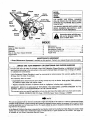
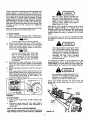
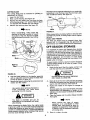
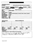
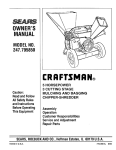
REAR
MODEL
NUMBER
SERIAL
NUMBER
THE MODEL AND SERIAL NUMBERS
WILL BE FOUND ON THE MODEL PLATE
Chute
Deflector
Chip-It
Spark Plug,
and Elbow
Leaf
Ramp
Muffler
YOU SHOULD RECO RD BOTH MODEL AND
SERIAL NUMBERS AND KEEP IN A SAFE
PLACE FOR FUTURE REFERENCE.
Air
Cleaner
Throttle
Control
Fuel
Tank
Model
Plate
bol are for personal safety. Be
Instructions
given
with this symsure
to follow
them.
FRONT
INDEX!i,:
"
;Warranty ........ . ................
• "M'F"
2
Rules for Safe Operation... ............ ;.... 3
Assembly ........................
...... 4
Operation ..............................
6
;How to Use Your Chipper-Shredder .. ......... 7
!Adjustments ............................
9
I
._ii
:'Maintenance
.....................
:, . _ ......
9
Off-Season
Storage
"
.11
Maintenance
Check List . ..i_"__i;:.' .' ._i._i._.,_i:......... 12
Trouble Shooting Chart ...................
12
Repair Parts ..........................
13-19
MAINTENANCE
AGREEMENT
A Sears Maintenance Agreement is available
on this product.
Contact your nearest Sears store for details.
..........._.... :_.LIMITED:ONEYEAR
::_!i.-:i#.i
i:"_:_i! _!_,::..::(_;:_
_:-:',.:F'I-:
h'-
WARRANTY
ON CRAFTSMAN
::_:_ _ .,'i -::?:
GAS CHIPPER-SHREDDER
:_:.'_,i_:
' (..
.
I
i=_!i:
..:...............
,.;_::'.i
_
'!iii_iFol_:i:_ei'ye.a[!from the date_
purchase, When:thisi:Ct'afts_an'Ch!pper-Shredder
is mairi:t$i'rled,"iEbricatea_,i_i:i
_' and t_ned u_: a_0rding tO the inS:LrUctions in the owner s manual, Sears wilt repair, free of charge, any defect
in material and workmanship,
i(_i:,_i
_::
:;,:_
i ', _':!:_::
Ifthis Craftsman Ch pper-Shredder isused forcommercia
30 days from the date of purchas_
......
This warranty does not cover: ....
--Expendab
e.Jtems, which become worn
i:!'ai_:€eaners,
'spark piugs andcatcher
-- Repairs necessary
WARRANTY
NEAREST
:
(_ ::,_7 :-,: i_ij
; _;
during normal .use, such as blades, blade, guides, blade adapte!:s,
_
bag's;
of operator
_..... " '
abuse or negligence,
!::_
including
SERVICE IS AVAILABLE BY RETURNING THE CRAFTSMAN
SERVICE
This warranty
because
or renta purpose, thiswarranty applies foronIy_!,
!
.... . ,...... ". i..... ;.",; ,:
:i
CENTER/DEPARTMENT
gives you specific
SEARS,
ROEBUCK
IN THE UNITED
STATES.
be_t
cranksl;_afts.
,...-.
: il.
CHIPPER:SHRE06ER TO _ri_E.
.
, ..
legal rights, and you may also have other rights which vary from state to stat_
AND
CO., Dept.
731CR-W,
Sears Tower, Chicago,
IL 60684
This unit is equipped with an internal combustion
engi,e andshoUid not be used on or near any unimproved forestcoverecl;"bri3sh;€o_iered
or grass-covered,
and un esstheengine_s
exhaust system:is equipped with a spark arrester
meeting applicable local or state laws (if any}. If a spark arrester is used, it should be maintained in effective working order by the operator.
' : :.:i_i!::,_:'..:.
::i
., In .the State,of California the above is required by law (Section 4442 of the California Public Resources Code): Other
states may have similar laws. Federal laws apply on federal lands. A spark arrester for the muffler
(see page 19) '
is available at your Sears AuthoriZed Service Center.:.
" ..,
,:.... ,.....
"
Jr
r
W=A_-=
RN IN G
__$:_'
= _ =9
To reduce the potential for'any injury, comply with the following safety instruc: _, Failure
• :•i_•:
_i '¸ _:i_
•ii_,•_•i_•_
_i_.;_:
:i•_ instructions....may
_ result
:
tions.
to complywith
the
in personal injury.
RULES FOR SAFEOPERATION
.....
"I:R INING
r
_
_:_i
•rOCkS,bottles, cans or other foreignobjects are not!
%:' Read this owner's manual carefully in its entirety _:_'_i
_rJncluded.
_
i_I_
iii I!
i before-: attempting to assemble or operate this
• 2. ff the cutting mechanism strikes any foreign object =i
_ machine. Be completely familiar with the controls
'::r,:;0rif your machine should start making anunusual
'_,:and the proper use of this machinebefore operating 'i _r_'_=_'
:__i_,noiseor vibration, immad ately Stopthe engine and .ir
it: Keep this manual in a safe p ace for future and
_ disconnectthe :spark plug wire fr0mthe spark plug_
regular reference and for ordering replacement ..... ..............
Allow the machine to stop and take the following=
parts.
:
'
_steps:
_
_ _
"
2. Children must never be altowed to operatethis
:, _=,I_A. Inspect for damage,
: ;
equipment.
;,: _
i,!=_ Replace orrepair any damaged partsl ....
3. ,No one should operate this unit while intoxicated or,::
c: Check for any loose parts and tighten to assure
while taking medication that impairs the sensesoI;r:;
:!_
i-i!: continued safe operation.
__
. _-i
reactions.
,,_: 3, !_The engine must be kept clean of debris and other,li:
4.i This equipment should never be operated in the ;_
_accumulations.
4. Do not allow an accumulation of processed material
i: vicinity Of children, pets or other persons,
to build up in the discharge area as this will pre5, Never run your machine in an enclosed area as the
vent proper discharge and can result in kick-back
exhaust from the engine contains carbon monoxfrom feed opening.
id;_,,_which is an odorless, tasteless and deadly
5. Never allow your hands or any other part of your
poisonous gas.
body or clothing inside the feeding chamber,
6, Never allow your hands or any part of your body or
discharge chute or near any moving part while the
clothing inside the feeding chamber, discharge
engine _s running.
. chute, or near any moving part while the machine
6, Keep all .guards and deflectors in place and in
or engine is running,
good working condition to assure continued safe
7. If it is necessary for any reason to inspect or repair
operation.
the feeding chamber or any part of the machine
7, Always stand clear of the discharge area when
where a moving part can come in contact with your
operating this machin_
=,.body or clothing, stop the machine, allow it to cool,
.... and disconnect the spark plug wire from the spark
8. Keep your face and body back from the feed
.... plug:before attempting such insPeCtion or rep_iir.
opening to avoid accidentatbounce back of any
material.
PREPARATION
9. Do not over:reach.: Keep proper balance, and
1. Wear safety glasses provided with your unit
footing at all times.
while operating the chipper-shredder to prevent in10. The engine governor settings on your machine
jury from any chips which may be ejected outof
must not be altered, changed, or tampered with.
the openings.
The governor controlsthe maximum safe operating
2. Wear proper apparel. Avoid wearing loose fitting
speeds and protects theengine and all moving
clothing, Wear gloves when handling material,
parts from damage caused by overspeed.
3. HANDLE FUEL WITH CARE as gasoline is an
11. Do not transport machine while engine is running.
extremely flammable fuel,
12. Do not operate=engine if air Cleaner or cover
A. Check the fuel before starting the engin_ Do
directly over carburetor air it_take is removes,
not fill the fuel tank indoors, while the engine
except for adjustment. Removal of such parts
is running, or while the engine is still hot. Turn
could create afire hazard.
the unit off and let the engine cool before
refueling.
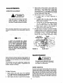
MAINTENANCE AND STORAGE
B. Fuel your chipper-shredder in a clean area. Do
not smoke while refueling.
1. When this equipment is stopped for servicing,
inspection, storage or to change an accessory,
.... C. Fuel tank cap must be secure at all times
make sure the spark plug wire is disc0nnectedfrom
.... except during refueling.
the spark plug. The machine should be allowed to
D. Avoid spillir_ggasoline or oil. Wipe the unit
cool down before making such inspection, adclean of any spilled fuel or oil.
justments, service, etc Maintain your machine with
E. Store fuel and oil in approvedcontainers, away
care and keep it clean for the best and continued
.:
from,heat or open flame, and out of reach of
safe operation.
children.
2. Do not use flammable solutions to clean the air
4. This machine should be operated only upon a
filter,
level earthen surface.
3.
When
not in use, your machine should be storedout
5. Assure that all screws, nuts and bolts and other
of the reach of children, Keep where gasolinefumes
_ fasteners are property secured.
will not reach an open flame or spark. For long
=OPERATION
periods of storage, the gasoline should be drained
'i. _=When feeding shreddable material into this equipand disposed in a safe manner. Always allow the
ment, be extemely careful that pieces of metal,
machine to cool before storing in any enclosure.
3
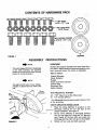
CONTENTS
OF HARDWARE
PACK
1/4÷20 x 1/2" Long
'
4EXLOGKNUTS
114-20
Thread
BOLTS
,
KEEPERS
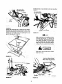
FIGURE 1
ASSEMBLY
I_
UNPACKING
NOTE
This unit is shipped WITHOUT GASOLINE
or OIL. After assembly, see operation
section of this manual for proper fuel and
engine oil recommendations.
:-
NOTE
The right a_d left' side of your chippershredder is determined from behind the
unit.
Hex Bolts
Hex Lock Nuts
INSTRUCTIONS
,/
Chute
Deflector
Rembve_thechipper:Shredder
and loose parts from
the carton, Make certain ail :parts and literature have
been removed before the car ton is discarded.
•
Parts in Carton:
Chippnr-ShrP-dder,
_
_
.....
Chute Deflector
Hopper
Upper Leaf Ramp Section
Catcher Bag
Hardware Pack
Safety .Glasses
';
"
"
:.... "
Tools Required for Assembly:
(2)
(!)
7/16" Open End of Box Wrenches*
1/2" Socket Wrench
* An Adjustable Wrench may be used in place of one
of the wrenches.
CHUTE
FIGURE 2
=
,,
DEFLECTOR INSTALLATION
1:
Place the chute deflector in position on the
discharge opening (on the left side of the
chipper-shredder). See figure 2,
2,
Secure chute deflector to discharge opening
with four hex bolts (1/2" long) and 1/4" hex lock
nuts. Heads of the hex bolts are inside the
discharge opening. Hex nuts go on the outside.
3,
Tighten
all four nuts and :bolts securely.
_
_
r
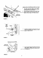
INSTALLATION OF HOPPER AND UPPER LEAF RAMP
Hopper j_
1.
The lower leaf ramp section on the chiPpershredder is placed inan uPright PoSitionfor shipping purposes. Lower,this Section:_ ,
2.
Place the hopper in position on the shredder. See
figure 3, Start all fou r self:tapping screws,, then
tighten securelyusing al/2"i_sOcketwrench.
Self-Tapping
Screws
jaf
:r :i': ....
Ramp Section
FiGuRE 3 .......
3.
Assemble the keeperstO_:the sides.:af_ithe unit
..........with two se f-tapping screws, using a 1/2",socket
__rench.
_ghte n sffcurety. _
i
\ \
Seff:Ta
Screw
FIGURE 4
Lower Leaf :
Ramp Section:_ :;i ,,
.
-ii
Place upper ieaframp section inside the lower leaf
ramp :section, Secure with:four
hex bolts
(ll2"long) and 1!4'ii t_ex:lock nuts. Tighten securely. Seefigure 5:1,"_'::_:!:
:i:
\
.
FIGURE 5. _:
---
Catcher
i
ATTACHING THE CATCHER BAG
_
_...
..........
, '
to the discharge opening._If desired,i placethe end of
on the drawstring, and release plunger,to lOck itlin
positiqn.,See figure 6..
_.
_.i _I_
__
the bag over the chute deflector: Depmss plunger,:pult
FIGURE 6.
ii
i ,, Ill IIIII,,m
I
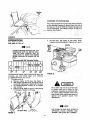
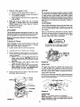
OPERATION
2.
GAS AND OIL FILL UP
il_
NOTE
ENGINE IS SHIPPED WITHOUT OIL. FILL
CRANKCASE WiTH OIL BEFORE STARTING. BE VERY CAREFUL NOT TO
ALLOW DIRT TO ENTER THE ENGINE
WHEN CHECKING OR ADDING OIL OR
FUEL•
__iRecommended SAE :Viscosity
Grades _
• ..........ii ,i
!;'r,
-20 °
0o
30W
32 °
or 10W30
60 °
80 °
Fill fuel tank. See figure 8. Use fresh,::_lean, :
unleaded automotive gasolin_ Capacity is 3 quarts.
Spark..._
Muffler
Plug,
Wire
and
_
_-_r--'--
I
Fuel
,__
I x ..........
Elbow
__
v/
nk
100 o
FIGURE 8•
TErvIPERATURERANGE EXPECTED BEFORENEXT OIL
CHI_NGE. ALL OILS MUST MEET A.RI. SERVICE
CL/_SStFICATION SD, SE, OR SF.
1. _ill engine with oil.
a. Remove engine oil fill plug. See figure 7•
b. With chipper-shredder level, fill engine with oil
to point of overflowing. Capacity is 1-1!4 pints.
-lilt chipper-shredder forward on its wheels,
then re-level.
d. Check oil level. Refill to point of over-flowing
if necessary. Replace oil fill plug.
:
.......
WARNING
Fill to'within _'1/2inch of topof fuel tank
to prevent spills and to allow for fuel
expans!on. If gasoline is accidently spifF
ed, mov e "chipper-shredder away from
.
areaof spi!!;Avoid creating any source of ...... .
ignition _until gasoline vapors have
• disappeared.
'_ •
Oil
Fill
/
USE CLEAN OIL AND FUEL. STORE IN
APPROVED, CLEAN, COVERED CONTAINERS. USE CLEAN FILL FUNNELS:;:
Oil Drain Plug
FIGURE 7.
.i6
i
Caution: Experience indicates that alcohol blended fuels
(called gasoho{ or using ethanol or methanol) can
attract moisture which leads to separation and forma,
lion of acids during storage` Acidic gas can damage the
fuel system of an engine while in storage= To avoid
engine =problems, the fuel system should be emptied
before Storage for 30 days or longer. Drain the gas tank,
start_the engine and let it run until the fuel lines and
carburetor are empty, Use fresh fuel next season.=iSee
St0rage _=section
of this
manual
for additional
WARNING
Wear the safety glasses provided with
your ii3nit while operating :th e chipper-_
.shredder to prevent injury from any chips_:
which
may
be ejected
out of the
Openings, Make certain chipqt guide is
• CloSed when not in use,
i
weari;:glm/es
When handling material. Feed material
into:_,ithe chipper-shredder
at a steady
rate. It is
pos_sible tofeed too fast, Experiment with feeding rates
to determine ,what rate provides
the best results
without stalling the engine or plugging the discharge
chute, _ :: :_
Never use engine or carburetor cleaner pr0du('ts_]n_:iihe
fuel tank or permanent damage lmay occur.
TO START ENGINE
::
1/_, Attach spark plug wire and boot to Spark plU9.:_.,
2. i Place choke lever in CHOKE position, See figure 9/
3.
4,
5.
6.
7.
The discharge chute will direct the shredded material
into a pileia container
or the bag provided with- your
shredder,
A warm engine may not require choking,
Place the throttle control lever in FAST position.
Grasp starter handle (see figure 9) and pull rope
slowly until engine reaches start of compressuon
cycle (rope wil! pull slightly harder at this p6int)i :
Let the rope rewind slowly.
!
•: :
NOTE
:A noise wBI,be heard when finding:the
:,
;start :of the compression
cycle. :_This
noise is caused by the flails and fingers
which
are part, of
the
shredding
mechanism
falling into place, and should
be expected.
Pull rope with a rapid,' continuoUS, fUll arm stroke.
Keep a firm grip on starter handle. Let rope rewind
slowly. Do not let starter handle snap back against
starter,
Repeat preceding instructions 4 and 5 until engine
fires,
:
:_:
After engine starts, move.throttle:control
lever on
engine to iDLE position for a few minutes warm up.
Move choke lever gradually to RUN position. Then
move throttle
control lever to ,FAST position for
shredding-chipping
operations.
CHOKE _
:
_
, ::: ::
Thechipper-shredder
discharges material :
;
with considerable
velocity.
Keep away- .....
from the area around _the discharge chute,
Always stop the engine and disconnect
the spark plug wire :when removing or
attaching
the
bag,
when
changing
containers
or when
remowng
the
shredded material.
If it becomes
necessary
to push materials into the
chipperJshredder,
use a small diameter
stick, NOT
YOUR HANDS. The stick should be small enough that
it w I be gL'0Und up if it gets into the impeller assembly.
! wA..,.G
_-
-
_
_
_-"
Do not deposit material larger then 1/2"
diameter in the hopper or upper guide
extension. Any materialheavier
then 1/2"
should be fed into the chip-it guide.
Leaves and smaller
branches
can be fed into the
hopper with the leaf ramp raised as shown in figures
10 and 1t.
!
,jo,,o.
"_t_
THROTTLE
FIGURE
9.
:
"
"
,
,Chip-it
i _:i
TO STOPENGINE
:" ..... '
_• _
I. Move throttlecontrollever to OFF position.See
figure 9.
; :.
_::_,:::i_!
2. Disconnect
spark pluglwire from spa_rk_ipi_g::ilto
prevent accidental
starting while equipment:_iis
unattended.
HOWTO
USE YOUR CHIPPER-SHREDDER
Your shredder is designed for safe, efficient Operation.
KEEP HANDS AND FEET AWAY FROM ALL OPENINGS.
FIGURE 10.
'
7
" "-
=, ;i".
Small 6ranches can also be fed into the leaf ramp. See
figure 14.
No larger than
1t2 inch diameter
Chip-It
< • :
::
Elastii:
Lock
Nuts
FIGURE 11.
......
Leaves and small=twigs can be raked into the chippershredder withtheleaf:ramp
lowered. To place in this
position, hold:_Pieedgeofthe leaf ramp, pull up on the
release_bar_ and.!gent!y lower the leaf ramp to the
ground: See :figures .112and 13...............
Ramp
FIGURE
14.
I_
NOTE
Bulky, material, such as stalks or heavy
branches (anything over 1/2", diameter, up
to 2" diameter), should befed into the
:chip-it guide. See figure 15. Do not force
or jam 'material into the chip-it guide.
Make certain leaf ramp is raisedas shown
in figure 15 when using.the chip-it guide.
1
WARNING
I
Make certain chip-it guide door is closed
When notin use.
::FIGURE:t2.
>:
' : ,
.=
Keep Leaf Ramp Raised
When Using Chip-it Guide
!
FIGURE 13.
FIGURE 15.
8
ADJUSTMENTS
__:
3,
With throttle in RUN position, close needle valve
clockwise {('_) until engine starts to loSe:Speed.
(lean mixture): Then slowly open needle valve
counterclockwise ((?'_) until engine JUST BEGINS
to run unevenly.This mixture should be.=rich
enough
, for best performance under load.....
4, Place throttle control in IDLE position:
WARNING
_ -:
-
_
__
a .....if engine idles, no further,adjustment_ is
• :_:::_
necessary.:
._._
_.
_:b. ,:If engine_idles too fast, turn idle :'sPeed
adjusting screw counterclockwise {f_) until
slower speed is obtained.
Ifany,adjustments are made to the engine
while the =engine if running : (e.g: carburetor),, keep clear-of alt moving parts,
Be careful of heated surfaces and muffler.
c.
if engine dies, turn idle speed adjusting screw
1/4 turn clockwise ((-_).
Place throttle,
....
contro in FAST position and restart engine....
d, Move throttle: :control to I_LE Positi0n,::,=:if
.. engine does note!die, repeat: step.c_ :: iii =:i
5 .....Test the engine by operating the chipper-shredder.
_ If engine tends to Stall or die :out;:;it: !_sually
indicates that the mixture is slightly lean and it magi
be necessary to open {P'_) the needlevatves!ightly_
: to:provide
a richer mixture, This richer
mixture may cause a slight unevenness"in,:idingl_
Minor carburetor adjustment may be required to compensate for differencesin fuel, temperature, altitude or
toad,
I_
Idle Speed " ......Throttl_ ;_
Adjusting Screw _ _Stol
_:
NOTE
; =_,.
_:,-
A:DIRTY AIR CLEANER WILL CAUSE
ENGINE: TO RUN:ROUGH. BE CERTAIN
AIR CLEANER1S CLEAN AND ATTACHED TO THE CARBURETOR BEFORE
ADJUSTING CARBURETOR. DONOT
MAKE UNNECESSARY,ADJUSTMENTS.
FACTORY SETTINGS ARE SATISFACTORY FOR MOST APPLICATIONS AND
CONDITIONS.
=
::
i:=!=: ":
: :.
::,
'
!
MAINTENANCE
Never attempt to:change maximumengine,
speed, ltis
pre-set at the:factory:and
should be changed only by
a qualified service technician who has the necessary
equipment.
Disconnect spark plug wire and =ground
it against the engine before performing,
any repairs or maintenanc_
_:
The carburetor may need re-adjusting if engine lacks
power or does not idle properly. If adjustments
are
needed, proceed as follows.
ENGINE LUBRICATION :,
:i
:
"'
Your four cycle engine will normaliyconsume some oil;
therefore check engine oil level regularly- approximately
every five-::h0urs of operation and before each usage.
Stop engine and wait several minutes before checking
oil level. With engine revel, theoil must be even with
the oil fill (refer to figure 7). Change engine oil after the
first two hours of operation, and every twenty-five
To Adjust Carburetor:
1. Close needle valve (See figure 16)€|0ci<Wise
((_) finger tight only. Forcing may cause damage.
Then open 1-1/2 turns counterclockWise_:(_).
2. Start engine and allow to warm for fiv e minutes,
hours thereafter,
9
: ...._::,:,
1.:= Drainlo!i_while engine is warm. '
'
:;
_;
-._,,,a, Remove oil drain plug. Refer to figure 7,=
:_i:_ Tipthe chipper-shredder forward, and catch oil
,:_,_'. in aisuitable container. ,_ _
.......
_:
When engine is drained of all oil;_replace'drain
plug securely.
• , _, .....
i ,,
2.
Refill with_fresh oil. Above 32°; _use oil labeled
SAE 30W or 10W30. Below 32 °, use oil /abeled
__:=5W20. Capaciw is 14/4 pints. Refer to "Gas and
:__Oil Fill-Up" on page 6 ......
_,_,
_,:_
i:
CLEAN ENGINE
Clean er_gineperiodically. Remove dirt and debris with
a cloth or_brush:=Cleaning with a 'forceful sp,_c,yof water
is not recommended as water could contaminate the
fuel system.
.....
: :!:
: .... _, -',:
=
_
......
r
_::_ .... _",:_,_:
_
_
CLONE"
Replace oi! fill plug,
A_R
3.
Yearly or every 50 hours, whichever occurs first, remove
the blower housing and clean the areas shown in figure
18 to avoid overspeeding, overheating and engine
damage. Clean more often if necessary.
Thea=r cleaner prevents damaging dirt, dust, etc,, from
entering_thbcarburetor and being forced into the engine
and is impOrtant to engine life and performanc_
To Service:Air Cleaner:
MUFFLER
.,
_
' ";::: ::i; :/:_
Do not operate the chipper:shredder witl_oUt a muffler
or tamper with the exhaust system. Damaged mufflers
or spark arresters could Create a fire haZard._InS'pect
periodically, and replace if necessary. If your engine is
equipped with a spark arrester screen assembly,remove
every 50 hours for Clean ng and inspection. Replace if
damaged,
:,
"
Periodicallyclean muffler area to remove
all grass, dirt and combustible debris.
more often under dusty conditions_:,
1,
Carefully remove pre-cteaner and cartridge,
2_
3.
Clean cartridge by tapping gently on a flatsurface.
If Very dirty, replacecartridge and pre_cleanerlor
Clean,as follows:
:...... • :
:" ';
!
a_- _Wash:in a low Or nonLsudsing detergent":iand
• warm water solution,, CAUTION: Donor use
' petroleum solventssuch as kerosene toclean
cartridg_
:., :;:,
b. Rinse thoroughly with. flowing water from
inside out until water is clear.
": _ ::_:!::,!_,i';
c. Allow cartridge to stand and air dry thoroughly
before using, DO NOT OIL CARTRIDGE OR
PRE-CLEANER. DO NOT USE PRESSURIZED
AIR TO CLEAN OR DRY CARTRIDGE.
4.
Insta!l cartridge and pre-cleaner. Tl_enciose cover
and fasten screws securely.
_,
i
Scl
Clean :Out
The spark plug should be cleaned and the gap reset
to .030"" at least once a season or every 50 hours of
operation. Spark plug replacement is recommended at
the start of each season. Refer to engine parts list for
correct spark plug type.
NOTE:DOnot blast clean spark plug.:Spark plug should
be cleaned by scraping orwire brushingand washing
with a Commercial solvent. , ....... :_:_;:: :•_ ; ;_i. _:,,
sc,ow
i":_
....
;030 Feeler Guage
ner
_Pre-Clea
:
"
_:
Cartridge .....
_r_
Plug
_"
FIGURE 19.
,
: :
?:,
:
FIGURE 17.
"
,LUBRICATION
,
•
iWheeisil- Ti_e wheels irequire no lubricai:ion!i '.
RaiisandFingers - If tile unit iS disassembled for any
reason, lubricate the flails and fingers With alight oil
_(engine oil may be used).
.... _
,_.
: : : : : :_::'=
10
CUTTINGBLADE
: The
CUtting
blade nnay
, ,.........
be removed
for
grinding
'
:_i_=:Theblade
canbe tested
by balancing it on a round Shaft
Or .... ,' !screwdriveror
nai!. Remove metal from the heavy" side
until it balanced evenly. See figure 21.
.....
:...... When 'reassembling,
make certain the ........_i.....
..... ::.....
.
opening on _he back up plate is toward
i
When reassembling
theblade, tighteht6 between375
......
the bottom of theunit,
The back up plate
_:
!
and 450 inch pounds, or lacking torque wrench, .tighten • .
............... may be ieversed to pi_ovide anew cutting ..........
_........securely,
.....................................
,
edge.
_:
_
i
_
!
"": _FLAILS AND FINGERS
:
::: "
-_
_i-/-,-!The.flails
and . fingers =may be.reversed
when they
/.. ,,i
become dull. It is suggested
that this procedure be
4'
"'.ii . performed byyour nearest Se_rsSe_rvice Departmen t`_ _
• OFF'SEASON
STORAGE
It is important to prevent gun deposits from forming
in essential fuel system parts such as the carburetor,
fuel hose or fuel tank during storage. Also, experience
indicates that alcohol blended fuels (called gasohol or
using-ethanol or methanol} can attract moisture which
. lead_, to separation and formation
of acids during
storage. Acidic gas can damage the fuel system'ofan
engine while in storage.
_To avoid engine problems, the fuel system should .be
" emptied before storage of 30 days or !onger. Follow
these instructions.
1.
Drain the fuel tank. Start the engine, and let it run
Until the fuel lines and carburetor are empty.
WARNING
FIGURE 20.
5.
6.
Hold the bladeietainer
on the imPeller assembly
DONUT DRAIN FUELWHILE SMOKING,
with an adjustable wrench to keep the blade from
OR IF NEAR AN OPEN FIRE.
turning as shown in figure 20.
' ..................................
Remove theblade by removing the center bolt, lock
2....Drain all the oil from the crankcase (this should
_-_,
NOTE
Use caution when removing the blade to
avoidcontacting
the weld _bolts
protruding from the housing.
_A
WARNING
The blade is reversible and can be
assembled to the crankshaft' with either
side Sl_owing. .........................
be
done after the engine has been operated and is still
.warm) .and refill crankcase with fresh oil.
3._ Protect the inside Of the engine for storage as
follows.
Remove spark plug, pour approximately 1/2 ounce
(approximately one tablespoon) of engine oil into
cylinder and crank slowly to distribute oil. Replace
-spark plug.
,.,,_:
4. Clean the engine and the entire chipper-shredder
thoroughly.
....
washer and flat washer.
....
_
.........
When sharpening
the blade, follow the origina!, angle
of grind as a guid_ It is extremely important that e_ch
cutting edge receives an equal amount of grinding to
preventan unbalanced blade, An unbalanced blade wilt
cause excessive vibration when rotating at high speeds
and may cause damage to the unit,
.
5.
11
.
W
NOTE
When
storing
any. type
of power
equipment
in an unventilated
or metal
storage shed, care should be taken to
rustproof the equipment.
Using a light oil
or silicone, coat the equipment, especially
all moving parts.
Store in a clean, dry area.
:i '
" i '
MAINTENANCE
/_
Check
Engine:Oil
Change
Level
, i _,
...._: : .9
Engine Oil
10
IIIIIII[IIIUIVIIIjIII
CleanEngine:
CHECK LIST
_r
::
..............
Ill
I
_
I
'
I
:
'
I
!_-:':,<
,
iiiiiiiiiiiil_
:.1.-
:,
"
.
i._ _-_-
,
_ ....
1:
Service
Clean
"_:'
Air Cleaner
:10,
or RepiaceSparkiPiug,
:'
":LI::'
:_'_"
....
_!
":/:_
Engilqe failst0
'_
I'_
:::_
110.......................
. :'!i::
'_!_'i _
SYMPTON
I:
......
,
. '
'i_:...
::
::
_ii
_.
....
ii
i:I ""
"
.
I.'Check _uel tank ifori_gas.
2. Spark plug lead Wire
i
li
',1 .........
,
.....
'_:=;_
SOLUTION
-_ POSSIBLE CAUSE(S)
:_tart _ "_;i_'_
_ii
",,,
1. Fiii tank if empty (Ix 6).
2. Connect lead wire (p. 7).
_disconnected.
.........
i
.....
..................
3, Clean, adjust gap Or replace
3. Faulty, spark plug.
;
"i:i
(p. 10).
illlll i
Hard starting or !oss of
power
•
i_:_i _i:_ :'
,1. Spark:plug
1. connect and tighten
wire:=(p. 7L
_.......•• i_:ii_i!'
3,, _iEngine
::
wire Ioos&
i iiii
Material not shredding
......
,:i:
.:
:_
i _ 1:Adjust
carburetor..See
adjustment_,,:
section (p. 9).::, ........ __i i,_ '.........:
2. Remove blower housing and clean
as described in the;maintenance
;> ,: section (p,,,10) ...........
air cleaner
as described
in
imaintenance section (p_ 10). _ ...._ :
3: Fiil Crankcase With the properoii
oi I level low.
...................
2 Clean
spark plug
,:_
tl_ 6).
ii ill
Blade and!or flaits not sharp.
Sharpen
or reverse
blade and flails
(1_ 11).
......!..!.,
Engine
stalls
bogs down
or
1,
No fuel
in fuel tank,
2. ::,Feeding material into the
! ::_machine too quickly.
1. Fill tank if emP_/ (p.
2. Do not force material:into'
the
: Feed gradually (p.' 7),i
: _,
opening.
=
NOTE: For repairs beyond the minor adjustments listed aboveiPtease contact yourSears Authorized Service Center.
_12
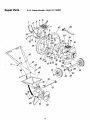
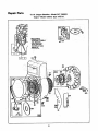
Repair Parts
5 H.R Chipper-Shredder--Model
247.796893
:i_:_Ii:::i!2
9
26
22
25
53
52
13
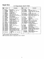
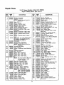
Repair Parts
.... :,
_i."
i
'S_
...._ .... =
5 H.R Chipper-Shredder--Model
Key.
No.
Part No.
Key
No.
Description
!
247.796893
Part No.
Description
33
11459A
Flail
11476
Door Chip it
710-0465
34
711-0564
Ftail Spacer 23/32"
Lg.
Hex Bolt 1/2-20 x 4.50" Lg.*
711-0580
Clevis Pin
35
71!-0578
_' CIm4s Pin .50" Dia. x 3,0" Lg,
711-0579
736-0237
F!ail Spacer 7132 '° Lg.
Fl.-Wash..406"
I.D. x 1,25'" O,D.
11455
..... Hdn,
_Cutting Finger
:.
L,-Wash.
3/8" .I,D. H.D.
736-0921
....
L-Wash.
112" I.D.'_
726-0111
Palnut 3/16" Dial
He× Bolt 318-24 x 2.0" Lg, H.T.
712-0922
Hex Jam Nut 112-20 Thd.*
39
14575--629_
Flad Housing Ass y,-Cump,
714-0507
Cottei_Pin
3132" Dia, x 314" Lg,*
40732-0546
'i. Torsion Spring .062 Dia. x 1,06
Chute Deflector
= ..'
16568
,, i.: .
712-0107 ...... L-Nut 1/4-20 Thd." ......
41
,11477 .....
; Chip-It. Guide Ass'y.
710-0289
Hex Bolt,;_/4-20
X 1.50" Lg,_:"*
42_ ,!1478:<
,,;" " Hinge Pin
.747_053t
Release Bar
714-01T4
Sq. Key !/4'" x '2_00" Lg. i: .... . : _ "_3
13430
Impeller Assembtv _
_: ' :=
.... : 44
712-0109'
Wing Nut Elastic 1t4-20 Thd.
710-0157
13431
,:,
, Blade
Hex Bolt 5/t_6:74 x 3/4" I_g.,t
'; 45
L-Wash, 5/16 _-I.D,*
......
= 46
736-0119' :i
11461B-;629
Upper Leaf Ramp Section
14573
47
t6524--629
Lower Leaf Ramp Section
Fl.-Wash, 5t16" I.D,
13o212-3112-01 Engine _ B&S 5 H.R
736-O264
:, '48
11464A .... _. Eng,i_e Mounting Plate
13481A-:629
: Hopper Assembly,
....
49
712-0123
7:10-0601
Hex Wash. Hd. Self-Tap Scr,
Hex:"Nut 51!6-24 Thd.*
,
,, :-. ,i 50,
736-0119
Lg. '_;, ,
5/16-18 x ;75"
,
L-Wash.
.
5[ 16 l, I.D. . :,
,:
'
"
" ;.:52 ::11454'
Back-Up Plate
,..
738-0521,
I Shaft =
16522
736-0170
' Speci&l L-Wash. 5116;' LD:
',:_'
53
Inlet Guide Assembly
.....
,11480
726-0221/
Stop Washer
Push Cap: ...... -,
:
55
710-0542
711-0494 .
Hex Bolt 5/16-18 x 8.38" Lg,,, = ,,
spacer
, , ', ....i
. , :
'56
7
8
9
10
tl
!2
13
14
15
16
17
18
19
20
21
22
23
24
25
26
28 :
29 ? 712-0429
30 _ :"-710-0237
7.14:0144
3i!
32
i 736-0192
*Common
Wheel Ass y.-Comp,
_ ,
' ',
Hex Bolt 5/16-24 x 1.50 ',Lg: *=
Elastic Lock Nut 5/!6-18 Thd. ,
Hex Bolt 5116_24 x ,62 " Lg. *
Cotter P n_1!8 '' Dia. x 1.00
Lg_,,
(Special)
•
........
FbWash. ,,53:t'" I.D. x .937 O.D. x
.O9 '
'
Hardware'_May
NOTE: Specifications
subject
bepurchased
to change
"57
59
60
_61
-----
735-0639
781-0420
781-0421
764-0199
723-0400
770-5875E
; '
Spark, Plug Elbow
.
Impeller Hsg. Support Brace-R.H.
Impeller Hsg. Support Brace-LH.
Part' of Engine /
....
Bag (Not Shown) .= "
Safety Glasses(Not
Shown)i :
Owner's
Manual =`` .....
i.,
locally.
without
notice
or obligation.
t4
,_
/'
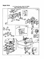
Repair
Parts
7
383
3O
i-
!_;:
•
....
'IO_
MA_AL
13s8
oAsK_'_Er!
lioI9 OECA[_KIT:I ' ,
) ;_
15
::
::i
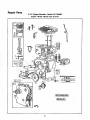
Repair Parts
5 H.R Chipper-Shredder-Engine.Model
130212
Model 247:_796893
Type 3112,01 =
r
.REQUIRESSPECIAL TOOLS
TO INSTALL.
SEE REPAIR
INSTRUCTION
MANUAL.
24
373
655
16
-
•
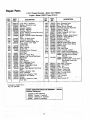
Repair Parts
5 H.R Chipper-Shredder.Model
247.796893
Engine.Mode!
130212 Type 3112-01
I, w ....
127A
127B
392
124
298
_467
643A'
17
0
Repair Parts
_!"
_ :PART
NO.
395990
2_ 297.565
3_
299819
211542
5
7 *270383
8 ,
294178
.9 ,. *27549
10_:
93394
11
66578
12 *270080
DESCRIPTION
KEY
.....................
DESCRIPTION
NO.
37; 222443
Cylinder Assembly
40 :_: ': 93312
Bushing-- Cylinder
:_ '
_
:
45:::: 260642
NOTE: Requires special tools foi;: ::!
46:, i.:212733
installation.
/:!: .........
*271937'
Seal--Oil
,_:_
55
_'
299431:_;
Head-- Cylinder
............ '
56._ 295871:
Gasket_Cytinder
Head
Bi;eather-Valve
Chamber
.,571
r. 4_O179
Gasket_Valve
Cover
58 _ " 66884
Screw_ Bieather Mtg. Sem:,i_ ......
59
230228
Grommet_Breather
Tube
:_::
; 66728"
:_Gasket-_,Crankcase'.015"
thick
60
65
94128
(standai_d) _._.'
.....
_r
NO_"
,..::_
KEY
"
r
5
7
16
....
_:Gasket _C/an kcase--.OOSi_ thick
66
399671
,Gasket_Crankcase_.O09
thick
67
394897
;Screw_ Cylin_er Head (2-3/32"
68
63770
long [ _!,i
93369
,298799.
14
Screw_Cylinder
Head (2-15/32". ........ 70
.394506,Iong)i
............................
71
15!
91249
Plug--Pipe,
1/4" Std. Sq0are Head
221923
73
To Replace Crankshaft Gear Pin,
Order Part No. 230978
74
93490
220865"
r397098
;Crankshaft
i
.,
I
'490533
,90
18
....298517
•-Cover Ass'y.--Crankcase,
" _"
95;i ,:_193499
Bushing-- Crankcase Cover
19
_!297603
NOTE: Requires Special tools for:.:,....
223793
, "_ installation.
490048
:;97
20
'2985Q4
Oil Seal and Spacer
21
....66768
108
_ 491177
Plug-- Oil, Filter
i231533
22
93032
Screw--Crankcase
Cover:M0unting
;118:
_93357
Sem
,. 134
220352
137
23; _:297229
,-Flywheel Assembly _
137A 223789
24
222698 ' _iKey-- Flywheel
.......
137B
223472
25:
298904
Piston Ass'y.-- Standard
149
26336
298905
;_Piston Ass'y.--.010"
O.S.
;:
152
260575
Ass'y,--.O20
I'
O3_:::,::_i,
:_
_
....
Piston
490589
:, 298906
298907
Piston AsS'y.-- 030 ' O
153
=_,
154
93527
PISTON RING SETS:
NOTE; For Chrome Pist0n Ring Set
"i63'
271935
--standai:d
Size_ Order,
,490554:
Part No. 299742,::. '-::.i.,
!80
490075
26_1 :298982
Ring
'
= 181
94094
190
298983
Ring Set .OlO';iO.S.:_PiS,ton ' ,
191 *271928
298984
Ring Set--.020"
O.S. Piston
20O .223886
298985
Ring Set--:O30,
O.S. Piston
201
262280
26026
Lock--Piston
Pin ,:
, ='....
27
262270
202
28
298909
Pin Ass*y._ Piston " standard,
, ....
203
280720
298908
Pin Ass'y.--Piston--,O05'"
O.S.
204 _, 222962
29
299430
Roe Ass y.--Connect
ng
,_::,0,,.
205
231520
NOTE: For Connecting R¢ d:with
'
2O8
262279
., .020'
ur_dersize C_ankpin
209
262283
:.
_ .i:i; Bore--Order
Nc_ 390459.
216
262359
30
221890
Dipper--Connecting
Rod _i.i
219
391737
221876 : Lock--Conn.
Rod Screw ;,/:
31
220
221551
32
92296
Screw--Connect!ng'Rod::.
222
490649
211119
Vaive--Exhaust
..... " i:
33
223
223455
34
261044
Valve.-- Intake
=.... .
224
93491
35
260552
Spring--Intake,Valve
36
..... 26478_
Spring--Exhaust
Valve
;:96
18
GuardFlywheel
Retainer--Valve
Spring
'
-Tappet--Valve
=,.
i Gear--Cam
.... _i,
Gasket--Carburetor
Mount ng (2)
Housing--Rewind
Starter
Pulley--Rewind
Starter (Inclucles
63" long rope):=
"
Spring--Rewind
Starter
Rope--Rewind
Starter--63"'
long
Pin--Starter
Grip
Grip--Starter
Rope
Screw--Stamped
Steel Housing
Mtg. Sem
Clutch Ass'y,--Rewind
Starter
Housing-- Starter Clutch
-.__:-i
Ball-- Clutch
Ratchet-Rewind
Starter
Washer
Clutch Retainer (Rubber
Coated)
Screen-Starter
Pulley •, :,
Screw-- Sem
.
"
_Washer
Spring
,
Carburetor Assembly
'
"
Screw--Throttle
Valve to Shaft
Sem
,_
Throttle--Carburetor
Shaft and Lever--Throttle
Valve Group--Choke
,.
,,
Valve_ Needle
_"
, , , ,.
Screw-- Hex. Head=
:
•:_"
Plug--Welch"i:
':
Plug--Welch
(Mixing Chamber) ....
Plug Welch (Well)
"
;, ".
Spring
Needle Valve
Spring--Throttle
Adjustment
Screw Ass'y.
'
",
Screw--Machine,
Rd.Hd.
5-40
x 5/8"
-....
_. Gasket--Air
Cleaner Mounting
'
Tank Assembly--Fuel
.....
Cap'Fuel
Tank "
. .. "
Screw
Fuel Tank Mounting
Sere
Gasket--Fuel
Tank Mounting,.
Guide--Air
•
'
Link--Governor
Link--Throttle
'
' ....: "
.
Crank--Bell
'
' .
Bushing
Governor Lever (Fla{)
Screw-- Shoulder_
Rod-- Control
Spring--Governor
Link--Choke
Gear
Governor
Washer--Thrust
Bracket--Control
Lever--Governor
Control
Rivet--Governor
Control Lever
Mounting
!Repair Parts
5 H.R Chipper-Shredder--Model
_J
r
_
Type 3112-01
KEY
NO, ::
PART
::;NO, .....
Lever Ass'y:'Goverhor
'
' '_ i 562q
Washer--Governor Lever
592
231082
Belt Crank
608
390463
Locknut-- Muffler
611
391813
Muffler--Exhaust
614
93306
Housing-- BIQWer"....
;'
615
93307
305
Screw--Blower HousingMounting
616
231077
306
Shfeld_'Cytinder ::.......
621 i 396847
307
Screw_ Cylinder Shietd:Mounting
:,'6134 i:."_271853
643
280737
308
221512
643A 280726
Cover--Cylinder
Head
655
222598
333
397358
Armature
Assembly
93414
676
395700
335
Screw--Armature
Mtg. Sem
337
298809
679
270382
Plug
Spark i-1/2" High-37-42 M.M.
680
221839
93705
725
223867
346
Screw-- Sem
356
398808
741
261696
Wire,_,Ground
........
Gasl_et Set - .....
.....
"
:/
358
397145
779
2622 76
363
851
221798
190.69 i
869
.....211787
373
92987
Nut-HeX.
::
383
89838
Wrench--Spark Plug
392 _!;:262328,,
Spring--, Fuel Pump Diaphragm
394
270026
Di&pl4ragrn
:
"
: 871 : ""231348
Washer
"
" _ "
414
220982
221377
Cap--Spring
432.
433= _ 93265 Pin--Diaphragm:Cover
,,, •
:.
434
210959
Cover_Diaphragm
.; ; " .... _
:_916 }:::280321
435 '
93141
Screw-- Diaphragm Cover
'
_966 _490074
467
399959
280715
Knob--Control
967
526i
• 93343
....
Screw--Tank •Bracket Mounting-:i_ " ' .. 9681- 223765
Sem _:':' .....
.':':
,.... -':969
.490073
527
223786
94018
Clamp--Breather Tube
971
528
231550
Tube--Breather
987
398970
529
67838
Grommet--Breather
Tube
995
223815
535: 271933
Elernent--Air Cleaner _ " :; ,- i ,110! 2
490507
542
93572
Screw
......
1016 ;. •490817
552
231079
Bushing--Governor Crank
.....
1019 ! 491100
(1/4" I.D.)
_
490374
222450
223813
261409
393368
490169
93158
221511
i 93490,
'
:!
130212
DESCRIPTION
.........
227
230
256
298
299
304
L
:_
"NO_!:
_
Engine--Model
247.796893
DESCRIPTION
Bolt-- Governor::Lever
Nut,Hex.-10-24
Starter Ass'y.-- Rewind
.Fuel Pipe and_!,C!ipAssembly
Cotter_Hair Pin.... • ';....
Retainer-E_Ring/; :_ i, '
Crank--Governor (1/4 Dia.)
Switch--Stop
Washer--Throttle Shaft (Foam)
Retainer--Foam Element
Retainer--Air
Filter
Anchor Spring
Deflector
Exhaust
_Washer Choke Shaft (Foam)
WaSher Choke Shaft (Brass)
Shield-- Heat
Gear--Timing
iLink
Belt Crank
;Cable Terminal-- Ignition
_Seat--tntake
Valve (Standard)
Seat-_Exliaust
Valve (Standard)
NOTE:
;_
Guide-NOTE:
For Options see Repair
ManLi'bl. ,!_ _ :: i
Exhaust Valve
63709 Guide--Intake Valve
See Repair Instruction
Manual.
Gear Rack--Governor
Base--Air Cleaner
Filter--Air
Cover Air Cleaner
Screw--Cover Mtg.
Screw--Air Cleaner
Seat--Throttle Shaft
Bracket-- Link
[,ink-- Retainer
Decal tL#b_.l)Kit ....
*included in Gasket Set-Part No. 397145. ....
!SPARK
ARRESTING
(Optional
MUFFLER
ASSEMBLY
Equipment|
Consists of the following:
392154
Screen (1 required)
223372
Deflector (1 required)
93705
Screw (4 required)
19
392390
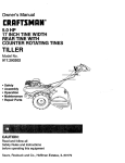
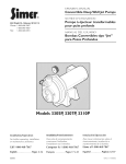
CRAFTS
OWNERS
MANUAL
5 H,P.
-S
HOW TO ORDER REPAIR PARTS
•_Each CHIPPER/SHREDDER has its own MODELINUMBER.
Each ENGINE has its own MODEL NUMBER. _
:IMODEL NO,
,\ , .
!
!¢
_ _
:_
_
The MODEL NUMBERfor the ENGINE wili_befdUnd onthe,ENGINE
BLOWER HOUSING.
,:_
Always mention these MODEL NUMBERS. wlien requesting service
or Repair Parts for your CHIPPER!SHREDDER;. "
i";-All parts listed herein .may be' ordered ti_rougt_:;_ny Sbars Service":
:CentedDepartments
and most Sears Stores.",
j-
HOW TO ORDER
REPAIR PARTS
WHEN ORDERING REPAIR PARTS, ALWAYSGIVE THE FOLLOWr:
• ING INFORMATION:
e. THE PART NUMBER
• THE PART DESCRIPTION
•
........
• _,H,E MODEL NUMBER 247.796893
g "J:_ENAME OF MERCHANDISE--CHIPPER-SHREDDER
• ,T_E_NGINE MODEL NUMBER
m
Sears, Roebuck and Co., Chicago, I!1.60684 U.S.A.
;II_]NTED
INU_S;A.: ......
Part No. 770-5875E
(24o_50_g9) 8/89