1
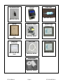
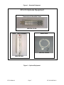
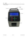
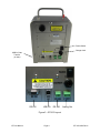
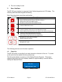
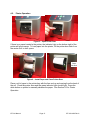
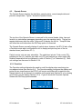
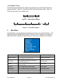
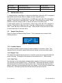
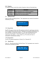
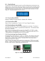
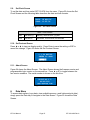
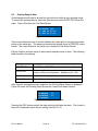
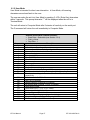
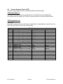
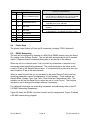
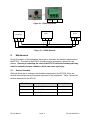
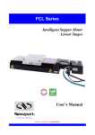
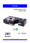
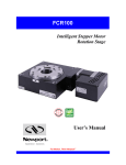
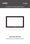
BT-610 MANUAL Met One Instruments, Inc 1600 Washington Blvd. Grants Pass, Oregon 97526 Telephone 541-471-7111 Facsimile 541-471-7116 BT-610-9800 Rev A Regional Service 3206 Main St. Suite 106 Rowlett, Texas 75088 Telephone 972-412-4715 Facsimile 972-412-4716 Copyright Notice BT-610 Manual © Copyright 2012 Met One Instruments, Inc. All Rights Reserved Worldwide. No part of this publication may be reproduced, transmitted, transcribed, stored in a retrieval system, or translated into any other language in any form by any means without the express written permission of Met One Instruments, Inc. Technical Support Should you require support, please consult your printed documentation to resolve your problem. If you are still experiencing difficulty, you may contact a Technical Service representative during normal business hours—7:30 a.m. to 4:00 p.m. Pacific Standard Time, Monday through Friday. Voice: (541) 471-7111 Fax: (541) 471-7116 E-Mail: Mail: [email protected] Technical Services Department Met One Instruments, Inc. 1600 Washington Boulevard Grants Pass, OR 97526 NOTICE CAUTION—Use of controls or adjustments or performance of procedures other than those specified herein may result in hazardous radiation exposure. WARNING—This product, when properly installed and operated, is considered a Class I laser product. Class I products are not considered to be hazardous. There are no user serviceable parts located inside the cover of this device. Do not attempt to remove the cover of this product. Failure to comply with this instruction could cause accidental exposure to laser radiation. BT-610 Manual Page 1 BT-610-9800 Rev A Table of Contents 1. Introduction ........................................................................................................... 4 2. Setup ...................................................................................................................... 4 2.1. Unpacking ............................................................................................................................ 4 2.2. Layout .................................................................................................................................. 8 2.3. Default Settings .................................................................................................................. 10 2.4. Initial Operation .................................................................................................................. 10 3. User Interface ...................................................................................................... 11 4. Operation ............................................................................................................. 11 4.1. Power Up............................................................................................................................ 11 4.2. Printer Operation ................................................................................................................ 12 4.3. Operate Screen .................................................................................................................. 13 4.3.1. Favorites ...................................................................................................................... 13 4.3.2. Sampling ...................................................................................................................... 14 4.3.3. Sample Status .............................................................................................................. 14 4.3.4. Sample History ............................................................................................................. 14 4.3.5. Warnings / Errors ......................................................................................................... 15 4.4. Sample Related Functions .................................................................................................. 15 4.4.1. Starting/Stopping .......................................................................................................... 15 4.4.2. Real-Time Output ......................................................................................................... 15 4.4.3. Sample Mode ............................................................................................................... 15 4.4.4. Sample Time ................................................................................................................ 15 4.4.5. Hold Time .................................................................................................................... 15 4.4.6. Sample Timing ............................................................................................................. 16 5. Main Menu ............................................................................................................ 16 5.1. Edit Main Menu Items ......................................................................................................... 17 5.2. Sample Setup Screen ......................................................................................................... 17 5.2.1. Location Number .......................................................................................................... 17 5.2.2. Sample Time ................................................................................................................ 17 5.2.3. Hold Time .................................................................................................................... 17 5.2.4. Samples ....................................................................................................................... 18 5.3. Settings Screen .................................................................................................................. 18 5.3.1. Count Units .................................................................................................................. 18 5.3.2. Temperature................................................................................................................. 18 5.4. Serial Screen ...................................................................................................................... 18 5.4.1. Report Type ................................................................................................................. 19 5.4.2. Baud Rate .................................................................................................................... 19 5.4.3. Serial Output Mode ...................................................................................................... 19 5.5. Printer Screen .................................................................................................................... 19 5.5.1. Printer .......................................................................................................................... 19 5.6. Favorites Screen ................................................................................................................ 20 5.6.1. Favorites Mode (ON/OFF) ............................................................................................ 20 5.6.2. Favorites Sizes (SIZE) ................................................................................................. 20 5.6.3. Favorites Alarm Limits (ALARM) .................................................................................. 20 BT-610 Manual Page 2 BT-610-9800 Rev A 5.6.4. Favorites Analog Output Scaling (A-SCALE) ................................................................ 20 5.7. Calibrate Flow Screen ........................................................................................................ 21 5.8. Set Sizes Screen ................................................................................................................ 21 5.9. Set Clock Screen ................................................................................................................ 22 5.10. Set Contrast Screen ........................................................................................................... 22 5.11. About Screen...................................................................................................................... 22 6. Data Menu ............................................................................................................ 22 6.1. Copy to USB Drive ............................................................................................................. 23 6.2. Recall Data ......................................................................................................................... 23 6.3. Printing Sample Data.......................................................................................................... 24 6.4. Memory Screen .................................................................................................................. 25 6.4.1. View Available Memory ................................................................................................ 25 6.4.2. Clearing memory .......................................................................................................... 25 7. Charging the Battery ........................................................................................... 25 8. Serial Communications ...................................................................................... 26 8.1. Commands ......................................................................................................................... 26 8.1.1. Computer Mode............................................................................................................ 26 8.1.2. User Mode.................................................................................................................... 27 8.2. Real Time Output ............................................................................................................... 28 8.3. Comma Separated Value (CSV) ......................................................................................... 29 8.4. Printer Style........................................................................................................................ 30 8.5. RS485 Networking .............................................................................................................. 30 9. Maintenance ........................................................................................................ 31 9.1. Service Schedule ............................................................................................................... 31 9.1.1. Zero Count Test ........................................................................................................... 32 9.1.2. Flow Rate Test ............................................................................................................. 32 9.1.3. Annual Calibration ........................................................................................................ 32 9.2. Flash Upgrade .................................................................................................................... 32 10. Troubleshooting .................................................................................................. 33 11. Specifications ...................................................................................................... 34 12. Warranty / Service ............................................................................................... 35 BT-610 Manual Page 3 BT-610-9800 Rev A 1. Introduction The BT-610 is a portable airborne particle counter with a small stable footprint. This allows you to move it around and set it down rather than holding it in your hand while sampling. The large character backlit LCD display provides easy viewing from distances exceeding 3 meters. Other key features include: 6 particle sizes (Defaults: 0.3, 0.5, 1.0, 2.0, 5.0 and 10 m) User size settings (0.1m steps from 0.3 to 2m, 0.5m steps from 2 to 10m) 2 Favorite sizes (including count alarm limits and analog output) Copy data to USB memory stick On Board Printer Serial communications (USB, RS232, RS485) Internal battery pack for portable operation (8 hours continuous) 2. Setup The following sections cover unpacking, layout and performing a test run to verify operation. 2.1. Unpacking When unpacking the BT-610 and accessories, inspect the carton for obvious damage. If the carton is damaged notify the carrier. Unpack and inspect the contents of the shipping container. The BT-610 is shipped with the standard items shown in Figure 1. Contact the supplier if any items are missing. Figure 2 shows optional equipment which can be purchased separately. ATTENTION: The included USB drivers must be installed before connecting the BT-610 USB port to your computer. If the supplied drivers are not installed first, Windows may install generic drivers that are not compatible with this product. To install USB drivers: Insert the Comet CD. The install program should run automatically and display the screen below. If an AutoPlay pop-up window appears, select “Run AutoRun.exe”. Finally, select “USB Drivers” to start the install process. BT-610 Manual Page 4 BT-610-9800 Rev A BT-610 Manual Page 5 BT-610-9800 Rev A Iso-Kinetic Inlet BT-610 Zero Filter MOI P/N: G3111 MOI P/N: G3110 Manual Battery Charger MOI P/N: BT-6109800 MOI P/N: 80643 Calibration Certificate USB Cable MOI P/N: BT-6109600 MOI P/N: 500784 Particle View Software CD Comet Software CD MOI P/N: 80248 Printer Paper MOI P/N: 750514 BT-610 Manual Page 6 BT-610-9800 Rev A Figure 1 – Standard Equipment BT-610 Optional Equipment Temperature & Humidity Probe MOI P/N: G3120 DwyerTM Ball Flow Meter Serial Cable MOI P/N: 550065 MOI P/N: 9801 Figure 2 – Optional Equipment BT-610 Manual Page 7 BT-610-9800 Rev A 2.2. Layout Figure 3 shows the layout of the BT-610 and the following table provides a description of the components. Carrying Handle Inlet Nozzle Temp/RH Connector Display Keyboard Printer BT-610 Manual Page 8 BT-610-9800 Rev A Power Switch Charger Jack USB for Data Transfer (on side) RS-232 USB I/O RS 485 Analog Out Figure 3 – BT-610 Layout BT-610 Manual Page 9 BT-610-9800 Rev A Component Description Display 4X20 character LCD display (backlit) Keyboard 8 key membrane keypad Printer On Board thermal printer Power Switch Switch that turns the BT-610 on or off (up for on). Charger Jack Input jack for the battery charger. This jack charges the internal battery pack and provides continuous operating power for the unit. Inlet Nozzle Ambient air inlet nozzle. Connect isokinetic probe to reduce turbulence in the air sample. T/RH Connector Mating connector for the optional external Temperature/RH sensor. USB I/O USB communication port USB Drive Export sample data to USB memory stick RS-232 Serial Port Connection used for serial communication RS-485 Serial Port Connection used for long distances (4,000 feet) or multi-drop (32 units) Analog out Two analog output channels (0-5V = 0 – FS Counts). FS (Full Scale) is settable from 0 to 9,999,999 counts. 2.3. Default Settings The BT-610 comes with the user settings configured as follows. Parameter Sample Location Sample Mode Sample Time Sample Hold Time Count Units Temperature Units Baud Rate Serial Output 2.4. Value 1 Manual 60 seconds 0 seconds CF C 9600 RS-232 Initial Operation Before operating the BT-610 for the first time, it is recommended that the unit be fully charged. Information regarding battery charging is found in Section 7. Complete the following steps to verify proper operation. 1. 2. 3. 4. 5. Press the top of the power switch to turn on power. Observe the Startup Screen for 2 seconds then the Operate Screen (Section 4.2) Press Start / Stop key. The BT-610 will sample for 1 minute and stop. Observe the counts on the display Use the up / down arrows to view other sizes BT-610 Manual Page 10 BT-610-9800 Rev A 6. The unit is ready for use. 3. User Interface The BT-610 user interface is composed of an 8 button keypad and a LCD display. The following table describes keypad functionality. Note: Some keys have more than one function. Key Starts or stops a sample (Operate or Main Menu Screen). Starts USB data transfer (Copy to USB Drive Screen). Starts printing data (Print Data Screen). Recalls the selected data (Recall Data Screen). DATA Loads the Data Menu Screen. MENU ESC Loads the Main Menu Screen. Loads the Operate Screen when in the Main Menu Screen. Cancel editing. Returns the field to the original value before editing began. ENTER Loads the screen associated with menu item. View history when Operate Screen is displayed. Stops editing a field and saves the changed value. ▲ ▼ Navigates up / down when not editing. Modifies field when editing. ◄ ► Navigates left / right START STOP 4. Description Operation The following sections cover the basic operation. 4.1. Power Up The BT-610 power is controlled by a switch located on the back of the unit. To power up the unit move the switch to the on position (up). The first screen shown on power up is the Startup Screen (Figure 4). This screen displays the product type and company website for approximately 2 seconds before loading the Operate Screen. BT-610 WWW.METONE.COM Figure 4 – Startup Screen BT-610 Manual Page 11 BT-610-9800 Rev A 4.2. Printer Operation Figure 5 – Open Printer Door If there is no paper loaded in the printer, the indicator light on the bottom right of the printer will glow orange. To load paper into the printer, lift the printer door latch from the center until to door opens. Paper Advance Figure 6 – Install Paper and Close Printer Door Place a roll of paper in the printer bay with the free end up and coming from the back of the roll. Close the printer door and the green indicator light should light. Press the white button on printer to manually advance the paper. See Section 5.5 for Printer Operation. BT-610 Manual Page 12 BT-610-9800 Rev A 4.3. Operate Screen The Operate Screen displays the date/time, sample status, current sample data and previous sample data. Figure 7 shows the Operate Screen. 15 AUG’10 11:23 L001 0.3µ 0 CF 0.5µ 0 CF 0.7µ 0 CF 1.0µ 0 CF 2.0µ 0 CF 5.0µ 0 CF Figure 7 – Operate Screen The top line of the Operate Screen is reserved for the normal header (date, time and location) or status/alarm messages depending upon the machine status. The top line remains stationary while the other 3 lines scroll to display the full list. Temp/RH data will follow the count data when the RH/Temp probe is connected. The Operate Screen normally displays 6 particle sizes; however, the BT-610 also offers a Favorites mode which configures the unit to display and print any two of the six standard sizes (see Section 4.3.1). Particle counts units are user selectable. The selections include: Total counts (TC), particles per liter (/L), particles per cubic foot (CF) and particles per cubic meter (M3). Ambient temperature can be displayed in units of Celsius (C) or Fahrenheit (F). Both unit settings are discussed in Section 5.2.4. 4.3.1. Favorites The Favorites setting eliminates the need to scroll the display when monitoring two non-adjacent sizes (see Section 5.4). The Favorites setting configures the display and printer for two sizes however the BT-610 still counts and buffers all six particle sizes. Sample data for all six channels is available via the serial port (Section 8) or by viewing count history on the display (Section 4.3.4). Figure 8 shows the Favorites Operate Screen with RH/Temp probe attached. 18 AUG’06 11:23 L001 0.3µ 0 CF 5.0µ 0 CF Temp 24C RH 40 % Figure 8 – Favorites Operate Screen w/ RH/Temp BT-610 Manual Page 13 BT-610-9800 Rev A 4.3.2. Sampling The Operate Screen displays current sample information when the unit is sampling (real time data). Concentration values (/L, CF, M3) are time dependent so these values may fluctuate early in the sample; however, after several seconds the measurement will stabilize. Longer samples (e.g. 60 seconds) will improve concentration measurement accuracy. Figure 9 shows the Operate Screen while sampling with RH/Temp probe attached. COUNTING… 58 L001 0.3µ 29,780 CF 0.5µ 1,400 CF TEMP 24C RH 40% Figure 9 – Operate Screen (Sampling) 4.3.3. Sample Status The top line of the Operate Screen displays the status of the BT-610 while the unit is sampling. The following table shows the various status messages and their meaning: Status STARTING… Description Starting the sample and waiting for the count system to initialize. COUNTING… 58 BT-610 is sampling. The time remaining is displayed to the far right. HOLDING…10 BT-610 is in auto mode and is waiting for the hold time to finish. The time remaining is displayed to the far right. 4.3.4. Sample History Sample history (previous data) can be viewed on the Operate Screen when the unit is stopped (not sampling). To view sample history, press the Enter key from the Operate Screen. The unit will display the last sample event (newest record) and display “” on the right side of the display (see Figure 10) to indicate history data. Press ◄ or ► to move through sample history one record at a time (◄ displays older events, ► displays newer events). Press the Enter key at any time to return to the Operate Screen. Press Start at any time to start a new sample. Sample history will display 2 channels in Favorites mode. To view other channels, change favorite sizes or disable Favorites mode (Section 5.4) before you view history. 15 AUG’10 11:23 L001 0.3µ 0 CF 0.5µ 0 CF 0.7µ 0 CF Figure 10 – History Screen BT-610 Manual Page 14 BT-610-9800 Rev A 4.3.5. Warnings / Errors The BT-610 displays warning/error messages on the top line of the Operate Screen. These messages alternate with the normal date/time header. The following table lists the warning/error messages: Display Message Description <COUNT ALARM> Count alarm. The count is >= the alarm limit. LOW BATTERY! Low battery warning. Less than 15 minutes of normal operation remaining. Recharge the battery FLOW ERROR! The sample flow rate is not within +/- 10% of the nominal 0.1 CFM flow rate. SENSOR ERROR! Particle sensor error. 4.4. Sample Related Functions The following sub-sections cover BT-610 sample related functions. 4.4.1. Starting/Stopping To start or stop a sample, press the START/STOP key. A sample event can be manually started or stopped from either the Operate Screen or the main menu. 4.4.2. Real-Time Output BT-610 provides real-time output on the serial port at the end of each sample. The format of the output is controlled by the Serial Output setting (Section 5.4). 4.4.3. Sample Mode The sample mode controls single sample or continuous sampling. The Manual setting configures the unit for a single sample. The Auto setting configures the unit for continuous sampling. 4.4.4. Sample Time The sample time determines the amount of time that counts are accumulated. The length of the sample is user settable from 1 – 999 seconds and is discussed in section 5.2.2. 4.4.5. Hold Time The hold time is used when the sample mode is set to auto (continuous sample). The hold time represents the time from the completion of the last sample to the start of the next sample. The hold time is user settable from 0 – 999 seconds and is discussed in section 5.2.3. BT-610 Manual Page 15 BT-610-9800 Rev A 4.4.6. Sample Timing The following figures depict the sample timing sequence for both manual and auto sampling modes. Figure 11 shows the timing for manual sample mode. Figure 12 shows the timing for auto sample mode. Start Time Sample Time Stop Time Figure 11 – Manual Mode Sample Start Time Sample Time Hold Time Sample Time Stop Time Figure 12 – Auto Mode Sample 5. Main Menu The Main Menu is accessible by pressing the menu key on the Operate Screen. The table below shows the Main Menu items. Press ▲ or ▼ to navigate to a menu item then press Enter to display a screen where you can view or change item setting(s). SAMPLE SETUP SETTINGS SERIAL PRINTER FAVORITES SET SIZES CALIBRATE FLOW SET CLOCK SET CONTRAST ABOUT Figure 13 – BT-610 Main Menu Menu Item Description Press Enter to navigate to… SAMPLE SETUP View / change location number, auto / manual mode, sample time and hold time. Sample Setup Screen SETTINGS View / change volume (count units) and temperature units ºC / ºF. Settings Screen SERIAL View / change Serial Report type, Baud Rate and serial mode. Serial Screen PRINTER View / change Printer enable setting Printer Screen FAVORITES Set count alarm limits for 2 particle sizes Count Alarm Screen SET SIZES Set particle sizes Set Sizes Screen CALIBRATE FLOW Calibrate the sample flow rate Flow Screen BT-610 Manual Page 16 BT-610-9800 Rev A SET CLOCK Set the date and time. Set Clock Screen SET CONTRAST Adjust the display contrast. Set Contrast Screen ABOUT Display firmware version and serial number. About Screen 5.1. Edit Main Menu Items To change settings, press Menu to display the Main Menu, press ▲ or ▼ to navigate to the desired item and press Enter to display the item view/edit screen. To edit pick list items (e.g. Sample Setup - Auto/Manual), press ▲ or ▼ to navigate to the item. Press Enter to select the item. Press ▲ or ▼ to change the setting. Press ENTER to save the setting or ESC to cancel and return to the main value. To edit numeric values (e.g. Count Alarms - Alarm Limit), press ▲ or ▼ to navigate to the item. Press Enter to select the item. Press ▲ or ▼ to increment or decrement a value. Press ◄ or ► to select the next digit. Press ENTER to save the value or ESC to cancel and return to the main value. 5.2. Sample Setup Screen Figure 14 shows the Sample Setup Screen. The 4 parameters are covered in the following sections. LOCATION: SAMPLE TIME: HOLD TIME: SAMPLES: 001 060 000 SINGLE Figure 14 – Sample Setup Screen 5.2.1. Location Number The location number is used to assign a unique number to a location or area. This important field is included in sample data records (display, printer and serial output). 5.2.2. Sample Time The sample time determines the amount of time that counts are accumulated while the pump is running. The length of the sample is user settable from 1 – 999 seconds. 5.2.3. Hold Time The Hold time is the time between samples when sampling in Auto mode (continuous). The Hold time is user settable from 0 – 999 seconds. The pump will remain on during the hold period if the Hold time is 60 seconds or less. The pump will stop after each sample, and start a few seconds before the next sample, if the Hold time is greater than 60 seconds. Hold times greater than 60 seconds will increase pump life. BT-610 Manual Page 17 BT-610-9800 Rev A 5.2.4. Samples The samples setting controls the number of samples to take as illustrated below. Selection 5.3. Description REPEAT Repeat configures the unit for continuous sampling. SINGLE Single configures the unit for a single sample. 002-999 Configures the unit to take N samples. Settings Screen Figure 15 shows the Settings Screen. The 4 parameters are covered in the sections immediately following. COUNT UNITS: CF TEMPERATURE: C Figure 15 – Settings Screen 5.3.1. Count Units The BT-610 supports total counts (TC), particles per liter (/L), particles per cubic foot (CF) and particles per cubic meter (M3). Particle count information updates while the unit is sampling. Concentration values (/L, CF, M3) are time dependent so these values may fluctuate early in the sample; however, after several seconds the measurement will stabilize. Longer samples (e.g. 60 seconds) will improve concentration measurement accuracy. 5.3.2. Temperature The BT-610 displays temperature in Celsius (C) or Fahrenheit (F). 5.4. Serial Screen Figure 16 – Serial Screen shows the Serial Screen. The 3 parameters are covered in the sections immediately following. REPORT: CSV BAUD RATE: 9600 SERIAL OUT: RS-232 Figure 16 – Serial Screen BT-610 Manual Page 18 BT-610-9800 Rev A 5.4.1. Report Type The Report setting determines the output format for the Serial Port. The choices are NONE, CSV and PRINTER. When set to NONE, the unit will not automatically output the reading at the end of a sample to the Serial Port. CSV is a Comma Separated Values output format suitable for importing into a spreadsheet. PRINTER is the same format as the screen and panel mounted printer. This setting does not affect the panel mounted printer which always prints in PRINTER format. 5.4.2. Baud Rate Use the Baud Rate selection to set the serial communications baud rate. BT-610 communicates at baud rates from 300 – 38400. 5.4.3. Serial Output Mode The Serial Output setting controls the behavior of the BT-610 serial output. The modes are RS232, RS485, Printer or Network (see Section 7 for serial communication protocol). The following table lists the Serial Output settings and describes their meanings. Serial Output Setting Description RS232 RS232/USB communication. RS485 RS485 communication. NETWORK RS485 communication with all serial output suppressed unless specifically addressed. 5.5. Printer Screen Figure 17 shows the Printer Screen. The 3 parameters are covered in the sections immediately following. PRINTER: ENABLE Figure 17 – Printer Screen 5.5.1. Printer The Printer setting selects whether to ENABLE or DISABLE the panel mounted printer for automatic output at the end of each sample. The panel mounted printer always prints in Printer format regardless of the Serial Output format specified. BT-610 Manual Page 19 BT-610-9800 Rev A 5.6. Favorites Screen The Favorites mode eliminates the need to scroll the display when monitoring two nonadjacent sizes. The Favorites mode also provides count alarm limits and analog output scaling for the Favorites (2 count channels). The Favorites mode controls the display (real time and history) and printer format. The CSV serial output includes all 6 sizes. Figure 18 – Favorites shows the Favorites screen. FAVORITES ON SIZE ALARM A-SCALE 0.3 0500000 0500000 5.0 0500000 0500000 Figure 18 – Favorites 5.6.1. Favorites Mode (ON/OFF) Enables or disables Favorites mode (On = Enabled, Off = Disabled). 5.6.2. Favorites Sizes (SIZE) Select 2 of the 6 standard sizes. Favorite 1 is 0.3 m in Figure 18 (above). 5.6.3. Favorites Alarm Limits (ALARM) Favorites count alarm limit. A zero (0) value disables the count alarm. The alarm is active when the count is equal to or greater than the alarm limit. The maximum alarm limit value is 9,999,999. Alarm values do not change with the count units setting (TC, /L, CF, M3). In other words, a value of 1,000 will alarm at 1,000 counts or 1,000 particles per cubic foot or 1,000 particles per liter depending on the count unit setting. 5.6.4. Favorites Analog Output Scaling (A-SCALE) Favorites analog output scaling (0 – 5 volts = 0 – VALUE). The maximum scale value is 9,999,999. A zero (0) value will configure the analog output for a digital or binary alarm (0 volts = normal, 5 volts = alarm). The alarm limit for this binary mode is configured in Section 5.6.3 above. Figure 19 shows the analog output connector pin assignments. GND pins are signal ground. A1 and A2 are Analog Output 1 and Analog Output 2 which are associated to Favorite 1 and Favorite 2 respectively (see Section 5.6.2). GND A2 GND A1 Figure 19 – Analog Output Connector BT-610 Manual Page 20 BT-610-9800 Rev A 5.7. Calibrate Flow Screen The BT-610 has a factory calibrated flow rate of 0.1 CFM (2.83 LPM). Under normal circumstances, the integrated flow control system will maintain flow within +/- 5% of this flow rate. Use the following procedure to calibrate the flow rate when a periodic flow rate check (Section 9.1.2) indicates a flow rate error greater than +/- 5%. 1. Connect a reference flow meter to the inlet fitting on the top of the unit. 2. Access the Calibrate Flow screen by pressing Menu then select Calibrate Flow. The pump will start automatically when you enter the Calibrate Flow screen and stop when you leave the screen. The system will wait several seconds for the flow to stabilize. During this time, the unit will display “Waiting...” 3. Afterwards, use the up and down arrow keys to adjust the flow until the reference flow meter reads within tolerance. You will need to wait a few seconds after each adjustment for the flow system and the reference meter to stabilize. Figure 20 shows an example of the Calibrate Flow Screen. 4. When the desired flow rate is reached, press ENTER to set the calibration. 5. Exit the Calibrate Flow screen by pressing the ESC button (the pump will stop). CALIBRATE FLOW ADJUST FLOW ▲▼ ENTER TO SET Figure 20 – Calibrate Flow 5.8. Set Sizes Screen The BT-610 has six standard factory calibrated particle sizes. These standard sizes will support most applications and provide the best size accuracy (+/- 10%). This unit also supports custom sizes. These sizes are configured using the Set Sizes Screen (Figure 21). Custom size thresholds are interpolated using the standard size calibration curve. Therefore, the size accuracy for custom sizes is somewhat reduced (+/- 15%). SET SIZES 0.3µ 2.0µ 0.5µ 5.0µ 1.0µ 10.0µ Figure 21 – Set Sizes Screen The unit sorts sizes from small to large after each size change. Duplicate sizes are not allowed. Any attempt to set two or more sizes to the same value will result in a “DUPLICATE SIZES!” warning message. BT-610 Manual Page 21 BT-610-9800 Rev A 5.9. Set Clock Screen To set the date and time select SET CLOCK from the menu. Figure 22 shows the Set Clock Screen and the following table describes the date and time formats. SET CLOCK DATE: 18 AUG’06 TIME: 11:25:36 Figure 22 – Set Clock Screen Date / Time Formats Date dd mmm’yy dd=day, mmm=month, yy=year Time hh:mm:ss Hh=hours, mm=minutes, ss=seconds 5.10. Set Contrast Screen Press ◄ or ► to improve display quality. Press Enter to save the setting or ESC to cancel the change. Figure 23 shows the Set Contrast Screen. SET CONTRAST < > TO ADJUST ENTER TO SAVE ███████ Figure 23 – Set Contrast 5.11. About Screen Figure 24 shows the About Screen. The About Screen shows the firmware version and programmable logic version on the second line. Press ▲ or ▼ to toggle between the two version numbers. The serial number is shown on the third line. BT-610 80203 R0.1.0 SN A10000 www.metone.com Figure 24 – About Screen 6. Data Menu To access data options (copy data, view available memory, recall data and print data), simply press the Data key to navigate to the Data Screen. Figure 25 shows the Data Screen. BT-610 Manual Page 22 BT-610-9800 Rev A COPY TO USB DRIVE RECALL DATA PRINT DATA MEMORY Figure 25 – Data Screen 6.1. Copy to USB Drive Figure 26 shows the Copy Data Screen. The BT-610 will copy all data from the displayed date/time to current time. Initially, the date/time will be the first sample record so all records will be copied. To reduce transfer time, press Enter and change the date/time to a more recent date/time. COPY TO USB DRIVE FROM 01 JAN’10 12:00 PRESS START TO BEGIN Figure 26 – Print Data Screen Press the Start button to initiate the copy process. Press the ESC button to cancel the copy process and return to the Data menu. The following screen is displayed during the copy process (Figure 27). COPY TO USB STATUS COPYING SETTINGS… 50% COMPLETE Figure 27 – USB Status Screen 6.2. Recall Data Stored sample events can be viewed from the Operate Screen but this requires navigating one record at a time to reach a desired record. The Recall Data Screen provides a way to quickly navigate to a record based on time. Figure 28 shows the Recall Data Screen. RECALL DATA 01 JAN’00 00:00 Figure 28 – Recall Data Screen To recall data, enter the desired date/time and select the START/STOP button. The unit will recall the data from the date/time entered (if an exact match is found) or the next most recent data available. The unit will display “” on the right side of the display to indicate history data. BT-610 Manual Page 23 BT-610-9800 Rev A 6.3. Printing Sample Data Stored sample events can be printed via the serial port within a user selected range. To access the printing feature, press the Data key then select PRINT DATA from the menu. Figure 29 shows the Print Data Screen. PRINT DATA SERIAL LOCATION: 000 01 JAN’00 00:00 18 AUG’06 13:23 Figure 29 – Print Data Screen This screen allows the user to choose whether the output goes to the panel mounted printer or the serial port. The panel mounted printer always prints in PRINTER output format. The output format for the serial port is selected in the Serial Screen. Edit the location and time range to select which sample events to print. The following table describes the settings. Setting Description PRINT DATA Pick SERIAL or PRINTER for where to send the output. LOCATION The location ID of the sample events to print. Setting location to 000 prints all locations. Settable from 0 - 999 01 JAN’00 The date/time to begin printing sample events from. 18 AUG’06 The date/time to stop print samples. After the print settings have been selected, the Printing Status Screen is displayed. Figure 30 shows the Printing Status Screen as it would look when finished. PRINTING STATUS SCANNING...15 PRINTING...10 FINISHED! Figure 30 – Printing Status Screen Pressing the ESC button cancels the data printing and loads the menu. The format of the print is dependent upon the port setting (Section 5.2.4). BT-610 Manual Page 24 BT-610-9800 Rev A 6.4. Memory Screen The BT-610 memory is composed of a single file which contains the data from sample events. Every time a sample is completed, the BT-610 stores that data into the memory. The BT-610 memory is circular, meaning when the memory is full, the unit will start overwriting the oldest saved samples with new samples. BT-610 provides the user the ability to view the memory usage as well as clear the memory. 6.4.1. View Available Memory Memory Screen is used to view available memory or to clear the memory. The Memory Screen is accessed by selecting MEMORY from the Data Menu. Figure 31 shows the Memory Screen. FREE: 100% SAMPLES: 8000 PRESS ENTER TO CLEAR MEMORY! Figure 31 – Memory Screen FREE shows the percent of space available for data storage. When 0% is displayed, memory is full and the oldest data will be overwritten by new data. SAMPLES shows the number of samples which can be store in memory before the memory is full. When 0% is displayed, memory is full and the oldest data will be overwritten by new data. 6.4.2. Clearing memory To clear memory, press the ENTER key while viewing the Memory Screen. This will delete all the sample events in memory. A warning screen will be displayed to prevent accidental erasure. 7. Charging the Battery Caution: The provided battery charger is designed to work safely with this device. Do not attempt to connect any other charger or adapter to this device. Doing so may result in equipment damage. To charge the battery, connect the battery charger to an AC power outlet and the DC plug to the socket on the back of the BT-610. The battery charger is universal and will work with power line voltages of 100 to 240 volts, 50 to 60 Hz. The battery charger LED indicator will be Red when charging and Green when fully charged. A discharged battery pack will take approximately 3 hours to fully charge. When fully charged the battery inside the BT-610 will power the unit for about 8 hours of continuous sampling. Under normal operation, the battery will power the unit for about 24 hours. For continuous operation, operate the unit with the battery charger BT-610 Manual Page 25 BT-610-9800 Rev A attached. Charge the battery before storing the BT-610. Storing a discharged battery will degrade its performance. 8. Serial Communications BT-610 provides serial communications via USB and DB9 connectors located on the back of the unit. The following sections discuss the various serial communications. ATTENTION: The USB drivers must be installed before connecting the BT-610 USB port to your computer. If the supplied drivers are not installed first, Windows may install generic drivers that are not compatible with this product. To install USB drivers: Insert the Comet CD. The install program should run automatically and display the screen below. If an AutoPlay pop-up window appears, select “Run AutoRun.exe”. Finally, select “USB Drivers” to start the install process. 8.1. Commands The BT-610 provides serial commands for accessing stored data and settings. All commands are terminated by a carriage return. Also, these commands are not case sensitive. The following table lists the available commands. These commands are available via USB, RS232 and RS485 hardware interfaces. The settings (baud rate, parity and stop bits) must match the computer setting for proper communication regardless of the hardware interface type (USB, RS232 or RS485). 8.1.1. Computer Mode Computer Mode is intended for connecting the unit directly to a data logger or computer program such as Comet. This is the default mode of the unit. In Computer Mode, all commands are preceded by the <Esc> (ASCII 27) character. No characters are echoed back to the user when entering commands. All commands are executed using the <ENTER> key. Each time the <Esc> key is pressed, the unit will reset to Computer Mode and start the command input over. BT-610 Manual Page 26 BT-610-9800 Rev A 8.1.2. User Mode User Mode is intended for direct user interaction. In User Mode, all incoming characters are echoed back to the user. The user can wake the unit into User Mode by sending 3 <CR> (Enter Key) characters within 3 seconds. This prompt character “*” will be displayed when the unit is in Terminal Mode. The unit will return to Computer Mode after 2 minutes of inactivity on the serial port. The Q command will return the unit immediately to Computer Mode. Command ?,H 1 2 3 4 D T C S E ST RV ID FAx FSx SF SH SN SR SS CU TU RZ DT OP CS BT-610 Manual Settings (must match computer settings): Baud Rate = Selectable (see Section 5.2.4) Parity = None Stop Bits = 1 Description Displays the help menu Returns the units settings information Returns all available records from the data file Returns all records since last ‘2’ or ‘3’ command. Returns the last n records Date (mm/dd/YY) Time (HH:MM) Clear data Start a sample End a sample Sample Time Show software revision. Set/Get the Location ID. Range 1-999. Favorites alarm limit setting where x=1 or 2 for Alarm 1 or 2. Favorites size setting where x=1 or 2 for Alarm Size 1 or 2 respectively. Favorites mode. 0=Off, 1=On Hold Time in seconds Sample Number of Samples (0=Repeat) Set Report Mode (0=None, 1=CSV, 2=Printer) Read serial number Count Units (0=CF, 1=/L, 2=TC, 3=M3) Temperature Units (0=C, 1=F) Returns Channel Size information. Sets Date/Time without user interaction (string) Operational Status. S=Stop, R=Running, H=Hold. Set Channel Sizes (all 6 Channel Sizes) Page 27 BT-610-9800 Rev A 8.2. Real Time Output The real time output occurs when the unit finishes a sample. The output format is either a comma separated value (CSV) or a printer style depending on the Serial Report mode. BT-610 Manual Page 28 BT-610-9800 Rev A 8.3. Comma Separated Value (CSV) The CSV output fields are both comma separated and fixed length. CSV Header (Note 1): Time,Size1,Count1(M3),Size2,Count2(M3),Size3,Count3(M3),Size4,Count4(M3),Size5, Count5(M3),Size6,Count6(M3),AT(C),RH(%),Location,Seconds,Fav1Size,Fav2Size,Status CSV Example Record: 2013-09-30 10:04:05,00.3,08562345,00.5,01867184,00.7,00654892,01.0,00245849,02.0,00055104,05.0,0 0031790,+023,040,001,010,00.3,00.5,000,*00086 Field 1 2 3 4 5 6 7 8 9 10 11 12 13 14 15 16 17 18 19 20 CSV Fields Parameter Example Value Date and Time 2013-09-30 10:04:05 Channel 1 Size 0.3 Channel 1 Count (TC, /L, CF, M3) 8562345 Channel 2 Size 0.5 Channel 2 Count (TC, /L, CF, M3) 1867184 Channel 3 Size 0.7 Channel 3 Count (TC, /L, CF, M3) 654892 Channel 4 Size 1.0 Channel 4 Count (TC, /L, CF, M3) 245849 Channel 5 Size 2.0 Channel 5 Count (TC, /L, CF, M3) 55104 Channel 6 Size 5.0 Channel 6 Count (TC, /L, CF, M3) 31790 Temperature (C,F) 23 RH (%) 40 Location 1 Sample Time (0-999 seconds) 60 Favorite 1 Size 0.3 Favorite 2 Size 0.5 Status Bits (see below) 0 BT-610 Manual Page 29 Notes Note 2 Note 2 Note 2 Note 2 Note 2 Note 2 Note 2 & Note 3 Note 3 Note 4 Note 4 Note 5 BT-610-9800 Rev A Bit Status Bits Value Condition Notes (for table above): 1. CSV header included for multiple record transfers 0 OK (no alarms/errors) 0 1 1 Count alarm size 1 2 Count alarm size 2 2 4 Not used 8 Not used 3 4 5 6 7 16 32 64 128 2. 3. 4. 5. like All Data (2) or New Data (3). The CSV header does not print in Computer or Network mode. Units determined by product setting. Temperature and RH will be spaces (, , ) if Temp/RH probe is not attached. Favorite sizes will be spaces (, , ) if alarms are disabled. Status bit combinations are possible. For example, 17 (00010001B) = Low Battery and Size 1 alarm. Low battery Sensor error Not used Not used 8.4. Printer Style The printer output format is 9 lines by 26 characters (including T/RH if attached). 8.5. RS485 Networking The unit can be configured to operate in a Multi-Drop RS485 network using the Serial Out setting on the Settings Screen. The unit will also automatically be set to network mode if it detects network commands being sent to any device in the network. When the unit is in network mode, it will not echo any characters or respond to any commands unless specifically addressed. The network address is the same as the Location ID set in the Sample Setup screen. It is important that no two units have the same Location ID set in the same network. When in network mode, the unit is considered to be under Remote Control and key operating parameters cannot be changed by a local operator. These settings are: Sample Mode, Sample Time, Hold Time, Count Units and Temperature Units. The operator can still set the Serial Out to return the unit to Local Control. The Location can also be set to change the network address if necessary. For additional information on networking commands and addressing refer to the BT610-9801 Networking Supplement. Figure 32 shows the RS485 connector location and pin assignments. Figure 33 shows a RS-485 network wiring diagram. BT-610 Manual Page 30 BT-610-9800 Rev A GND + - Figure 32 – RS485 Connector G B+ A- Unit n Unit 1 Computer G G B+ A- B+ A- Figure 33 – RS485 Network 9. Maintenance Due to the nature of the instrument, there are no customer serviceable components in the BT-610. The case of the BT-610 should never be removed or opened for any reason. Opening or removing the case of the BT-610 voids the warranty and may result in exposure to laser radiation, which can cause eye injury. 9.1. Service Schedule Although there are no customer serviceable components in the BT-610, there are service items which ensure the proper operation of the instrument. Table 1 shows the service schedule for the BT-610. Time Period Item Manual Section Weekly Zero Count Test 9.1.1 Monthly Flow Rate Test 9.1.2 Yearly Annual Calibration 9.1.3 Table 1 Service Schedule BT-610 Manual Page 31 BT-610-9800 Rev A 9.1.1. Zero Count Test Air leaks or debris in the particle sensor can cause false counts which may result in significant count errors when sampling clean environments. Perform the following zero count test weekly to ensure proper operation: 1. Attach the zero count filter to the inlet nozzle (P/N G3111). 2. Configure the unit as follows: Sample Mode = MANUAL, Sample Time = 60 seconds, Volume = Total Count (TC) 3. Start and complete a sample. 4. The smallest particle size should have a count ≤ 1. 9.1.2. Flow Rate Test The flow rate test verifies the sample flow rate is within tolerance. The reference flow meter must be non-loading because the vacuum pump can be loaded down by external restrictions. Met One Instruments sells a suitable flow meter (P/N 9801). The flow rate test follows: 1. Connect a ±3% reference flow meter to the sample inlet nozzle. 2. Start a 5 minute sample. 3. The flow meter reading after ~3 minutes should be 0.1 CFM (2.831 LPM) ±5%. 4. The flow rate can be adjusted using the front panel (see Section 5.7) 9.1.3. Annual Calibration The BT-610 should be sent back to Met One Instruments yearly for calibration and inspection. The annual calibration cannot be performed by the customer because this calibration requires specialized equipment and a skilled technician. Met One Instruments maintains a calibration facility for calibrating particle counters according to industry accepted methods such as ISO, JIS and NIST. The annual calibration also includes inspection and preventative maintenance to improve product reliability. 9.2. Flash Upgrade BT-610 is firmware upgradeable via the serial connection using a Met One Instruments flash burn program. Binary files and the flash program must be provided by Met One Instruments. BT-610 Manual Page 32 BT-610-9800 Rev A 10. Troubleshooting The following section covers some common failure symptoms, causes and solutions. It is important to note that there are no customer serviceable components in this product. The BT-610 case should never be removed or opened for any reason. Opening or removing the case will void the warranty and may result in exposure to laser radiation, which can cause eye injury. Symptom Display does not turn on Pump does not turn on when a sample is started Keypad does not work Printer does not print Sample result is lower than normal Sample result is higher than normal Battery does not hold a charge BT-610 Manual Possible Cause Low Battery Defective Battery Low Battery Defective pump Loose connector Internal hardware failure Printer not enabled Paper not installed Paper not fed properly Flow rate is low Optics may be contaminated Flow rate is high Air leak in unit Optics may be contaminated Defective or worn out battery Defective charger Page 33 Solution Charge battery Send to service center Charge battery Send to service center Send to service center Enable printer Install paper Open printer door, reposition paper Perform flow rate test Send to service center Perform flow rate test Send to service center Send to service center Send to service center BT-610-9800 Rev A 11. Specifications Performance Particle Size Range Calibrated Sizes User Size Settings Concentration Range Accuracy Sensitivity Flow Rate Sample Time Hold Time Electrical Light Source Power AC Adapter/Charger Printer Communications Standards 0.3µm - 10µm, 6 channels 0.3 µm, 0.5µm, 1.0µm, 2.0µm 5.0µm and 10µm 0.1µm steps from 0.3µm - 2.0µm 0.5µm steps from 2.0µm - 10µm 0 – 3,000,000 particles per cubic foot (105,900 particle/L) ± 10% to calibration aerosol 0.3 µm 0.1 cfm (2.83 lpm) Adjustable: 1 to 999 seconds Adjustable: 0 to 999 seconds Laser Diode, 90mW, 780 nm 12V Li-Ion self-contained battery pack – Provides for 8 hours continuous use. Full recharge approximately 3 hours. AC to DC module, 100 – 240 VAC to 16.8 VDC @ 1.8 A 21 character per line thermal printer USB, RS-232 or RS-485 Meets ISO 21501-4 Interface Display Keyboard 20 character x 4 line LCD 8 key membrane type Physical Height Width Depth Weight 7” (17.7 cm) 6.6” (16.8 cm) 6.5” (16.5 cm) 5.00 lbs – 80 ounces – (2.27 kg) Environmental Operating Temperature Storage Temperature 0º C to +50º C -20º C to +60º C Accessories Supplied Optional BT-610 Manual Operation Manual USB Cable Comet Software Particle View Software Battery Charger Iso-kinetic Sample Probe Zero Particulate Filter Printer Paper (2 Rolls) (P/N BT-610-9800) (P/N 500784) (P/N 80248) Particle View (P/N 80643) (P/N G3110) (P/N G3111) (P/N 750514) RH & Temperature Probe Flow Meter Serial Cable (P/N G3120) (P/N 9801) (P/N 550065) Page 34 BT-610-9800 Rev A 12. Warranty / Service Warranty The BT-610 is warranted against defects and workmanship for a period of two (2) years from the ship date. Any product found to be defective during the warranty period will, at the option of Met One Instruments, Inc., be replaced or repaired. In no case shall the liability of Met One Instruments, Inc. exceed the purchase price of the product. This warranty may not apply to products that have been subject to misuse, negligence, accident, acts of nature, or that have been altered or modified other than by Met One Instruments, Inc. Consumable items such as filters, bearings pumps and batteries are not covered under this warranty. Other than the warranty set forth herein, there shall be no other warranties, whether expressed, implied or statutory, including warranties of fitness of merchantability. Service Any product being returned to Met One Instruments, Inc. for service, repair or calibration, including items sent for warranty repair, must be assigned a return authorization (RA) number. Please call (541) 471-7111 or send an email to [email protected] requesting an RA number and shipping instructions. All returns must be shipped to the factory, freight pre-paid. Met One Instruments, Inc. will pay the shipping charge to return the product to the end user after repair or replacement of an item covered by warranty. All instruments sent to the factory for repair or calibration must be free of contamination resulting from sampling chemicals, biological matter, or radioactive materials. Any items received with such contamination will be disposed of and the customer will be billed a disposal fee. Replacement parts or service/repair work performed by Met One Instruments, Inc. are warranted against defects in material and workmanship for a period of ninety (90) days from the date of shipment, under the same conditions as stated above. REV 2011 BT-610 Manual Page 35 BT-610-9800 Rev A