1
[
owners
manual
/
/
/
/
/
/
/
/
MODEL NO.
//
113.24350
it
/
/
/
/
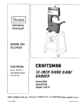
CRRFTSMRN
12-INCH BAND SAW/
CAUTION:
Read
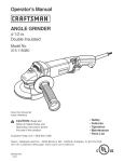
GENERAL
ADDITIONAL
and
SAFETY
INSTRUCTIONS
carefully
Sold
and
Part No. 69087
SANDER
assembly
operating
repair parts
by SEARS,
ROEBUCK
SIMPSONS-SEARS
AND
LIMITED,
CO.,
Chicago,
Toronto,
IL. 60684
U.S.A.
Ontario,
Canada.
Printed
In U.S.A,
If, within one year from date of purchase, this Craftsman Band Saw/Sander fails due to a
defect in material or workmanship, we will repair it free of charge.
This warranty service is available by simply contacting any Sears store or Service Center
throughout
the United States,
general
1. KNOW
safety
YOUR
POWER
instructions
12. USE SAFETY
TOOL
Read
the
owner's
manual
Carefully.
Learn
its
application
and limitations
as well as the specific
potential hazards peculiar to this tool.
2, GROUND
for power
3. KEEP GUARDS
and in working
IN PLACE
13, SECURE WORK
Use clamps or a vise to hold work when practical. It's
safer than using your hand, frees both hands to operate
tool.
14. DON'T OVERREACH
Keep proper footing
15. MAINTAIN
KEYS
5. KEEP WORK AREA CLEAN
areas and
benches
17. AVOID
invite
accidents.
DANGEROUS
Floor
7, KEEP
CHILDREN
All visitors
area,
8. MAKE
WORKSHOP
- with padlocks,
starter keys.
9. DON'T
be kept
a safe distance
from
Consult
work
switches,
or
owner's
STARTING
by removing
before plugging
ACCESSORIES
manual
for
recommended
that accompany
accessories may
PARTS
Before further use of the tool, a guard or other part
that is damaged should be carefully checked to ensure
that it will operate properly
and perform its intended
function - check for alignment of moving parts, binding of moving parts, breakage of parts, mounting, and
any other conditions that may affect its operation. A
guard or other part that is damaged should be properly
repaired or replaced.
It will do the job better and safer at the rate for which
it was designed.
10, USE RIGHT TOOL
to do a job it was not
11. WEAR PROPER APPAREL
No loose clothing,
gloves, neckties or jewelry
to get
caught
in moving
parts.
Rubber-soled
footwear
is
recommended
for best footing.
position
Serious injury could occur if the tool is tipped or if the
cutting tool is accidentally contacted.
Do not store materials above or near the tool such that
it is necessary to stand on the tool to reach them.
20. CHECK DAMAGED
or attaChment
such as
19. NEVER STAND ON TOOL
FORCE TOOL
Don't force tool
designed for.
the
accessories
accessories. Follow
the instructions
the accessories. The use of improper
cause hazards.
KID-PROOF
mas:er
ACCIDENTAL
Make sure switch is in "OFF"
in.
Keep
work
AWAY
should
changing
18. USE RECOMMENDED
ENVIRONMENT
Oon°t use power tools in damp or wet locations.
work area well lit, Provide adequate surrounding
space,
TOOLS
before servicing, when
blades, bits, cutters, etc.
must not I:)e slippery due to wax or sawdust.
6, AVOID
TOOLS WITH CARE
16, DISCONNECT
Form habit of checking to see that keys and adjusting
wrenches are removed from tool before turning it on.
Cluttered
and balance at all times.
Keep tools
sharp and clean for best and safest
performance.
Follow instructions
for lubricating
and
changing accessories,
order.
4, REMOVE ADJUSTING
AND WRENCHES
GOGGLES
Safety goggles must comply with ANS Z87.1-1968.
Also use face or dust mask if cutting operation
is dusty.
ALL TOOLS
This tool is equipped with an approved 3-conductor
cord and a 3-prong grounding type plug to fit the
proper grounding type receptacle. The green conductor
in the cord is the grounding wire. Never connect the
green wire to a live terminal.
tools
21.
DI RECTION
OF FEED
Feed work into a blade or cutter against the direction
of rotation of the blade or cutter only.
additional safety instructions for band saw/sander
Safety
is a combination
of
alertness
at all times when
operator
common
sense and
the band saw is being used.
k.
WARNING:
FOR YOUR
OWN SAFETY,
DO NOT ATTEMPT
TO OPERATE
YOUR
BAND
SAW UNTIL
IT I$
COMPLETELY
ASSEMBLED
AND INSTALLED
ACCORDING TO THE
INSTRUCTIONS
. . . AND
UNTIL
YOU
HAVE
READ
AND UNDERSTAND
THE FOLLOWING:
Use caution
Safety
Instructions
2. Getting
To Know
Your
for Power
Band Saw/Sander
3. Basic Band Saw Operation
4, Maintenance
5. Stability
Tools
......
.......
22
Of Machine
The band saw must be bolted
work bench, in addition,
if there
6. Location
so neither the operato stand in line with
7. Protection:
Eyes, Hands,
for indoor
use only.
Face, Ears, Body
a. Wear safety goggles that comply
with ANS Z87.1
1968, and a face shield if operation
is dusty. Wear
ear plugs or muffs during extended
periods of operalion.
Do not wear gloves.
, . roll tong sleeves above
the elbow.
b,
Do not
hand.
c.
Avoid awkward
hand positions,
where a sudden slip
could
cause a hand to move into the blade or the
sanding belt.
d.
e,
Never
table
except
devices
cut
pieces
of
material
too
small
to hold
by
turn your band saw "ON"
before clearing the
of all Objects
(tools,
scraps of wood,
etc.)
for the workpiece
and related feed or support
for the operation
planned.
Make sure the
blade
runs downward
toward
f.
Always adjust tension
ing belt being used.
correctly
h, When cutting a large piece of material,
supported
at table height,
i. Hold
the work
firmly
not
more
protective
removed.
cover
on
8. If any part of this band saw should break, bend, or fail
in any way or any electrical
component
fail to perform
properly,
or if any is missing, shut off power switch.
remove power supply
cord from power supply
and replace damaged
missing
and/or
failed parts before
resuming
operation.
9.
Read and follow
of the band saw.
the
instructions
appearing
on
front
DANGER
FOR
YOUR
OWN
SAFETY
1, READ AND UNDERSTAND OWNER'S MANUAL BEFORE OPERATING THIS MACHINE.
2.
ALWAYS
WEAR
SAFETY
ATING
THIS
MACHINE.
GOGGLES
BE
BLADE
POSITIVE
THE
SAW
PROPERLY-TEETH
POINTING
WARD
THE
TABLE_BEFORE
HINE.
4.
BE SURE
THRUST
BEFORE
UAL.
ADJUST
7.
UPPER
MINIMIZE
INJURY
SAW
BLADE
OR
A SAFE
WHEN
IS
OPER
INSTALLED
DOWNWARD
OPERATING
TOMAC-
BLADE
GUIDES,
AND
PROPERLY
ADJUSTED
MACHINE-SEE
BY NO MORE
FINGERS
make sure it is
BLADE
TENSION,
BEARINGS
ARE
OPERATING
ALWAYS
PIECE
6.
j. Do not feed the material
too fast while
cutting.
Only feed the material fast enough so that the blade
wilt cut. Keep fingers away from the blade.
rotate
work-
Never operate the band saw with
the unused shaft end of the motor
than
against the table.
plug from power
from band saw.
o.
for the blade or sand-
blade guides
when cutting.
as
Never leave the band saw work area with the power
on before the machine has come to a complete
stop,
or without
removing
and storing
the switch
key.
5.
g. Always
adjust the upper
1/4" abeve your material
such
n.
the table
in the right direction.
Always adjust tracking
wheel
correctly
so that the blade does not run off the wheels.
material
Insert a screwdriver
or wedge in the kerf..,
the wheels by hand while backing
up the
piece.
band saw to tip over or move during
certain operations
such as cutting
long heavy boards. The band saw should
be bolted to the floor.
the blade. This band saw is intended
round
1. Turn off the band saw., . remove
source outlet
. . . remove cover
securely to a stand or
is any tendency
for the
The band saw should be positioned
tor nor a casual observer is forced
off
m. When backing up the workpiece,
the blade may bind
in the kerf (cut) . . . this is usually caused by sawdust
clogging up the kerf. If this happens;
21
...........................
cutting
ga u ge.
2
18
..................
when
dowel
rods, or tubing.
They have a tendency
to roll
while being cut causing the blade to "bite",
Always
use a "V" block, or clamp round material
to a miter
PAGE
1. General
Use caution
when cutting
off material
which
is irregular in cross section which could pinch the blade
before the cut is completed.
A piece of molding
for
example
should lay flat on the table and not be permitted to rock while being cut.
GUIDE
THEN
1/4
POTENTIAL
SANDING
DISTANCE
MAINTAIN
CONTROL
OF
ALL TIMES-HOLD
FIRMLY
OWNERS
TO
CLEAR
MAN-
WORK
INCH.
OF CONTACT
WITH
BELT
BY
KEEPING
AWAY.
THE
WORKEIECE
AT
AGAINST
THE TABLE,
8, BE ATTENTIVE
TO THIN CUT-OFF
PIECES {"I_ITING END OF SLOT IN INSERT, OR JAMMING tN
SLOT.
10. Think
Safety, Safety is a combination
of operator common sense and alertness at al! times the band saw/sander
is operating.
dditional safety instructions
_r band saw/sander
_RNING:
THE 5" BAND SAW PULLEY AND THE
I/2" MOTOR PULLEY FURNISHED, WILL RUN THE
.ADE AT APPROXIMATELY
900 RPM (OR 2700
"ET PER MINUTE) WHEN USED WITH A 1725 RPM
I)TOR. NEVER SUBSTITUTE
THESE PULLEYS TO
kCREASE THIS SPEED BECAUSE IT COULD BE DANEROUS.
WARNING:
DO NOT ALLOW FAMILIARITY
(GAINED
FROM FREQUENT USE OF YOUR
BAND SAW) TO
BECOME COMMONPLACE. ALWAYS REMEMBER THAT
A CARELESS FRACTION OF A SECOND IS SUFFICIENT TO INFLICT SEVERE INJURY.
motor specifications and electrical requirements
ihis
This machine
is designed
_o iJq_ _ 1725 RPM m_m;_t on!v
Do not use any motto
drlt
rLlr_S _J-qet than 1725 RPM.
It is wired for operation
o_ I10 t20 toll,,
60 H,_., dt_er
nating
current.
IT
MUST
NOT BE CONVEITT_D
lO
OPERATE
ON 230 VOLTS.
EVEN
]'HOUGI_
,qO_,_E OF
]HE
RECOMMENDED
MOTORS
ARE DUAL VOLTAGE.
pmug
THESE CRAFTSMAN
MO_rORS t4AVE BEEN
FOUND
TO BE ACCEPTABLE
FOR USE ON
THIS TOOL.
HP
RPM
VOLTS
CAIALOG
1/2
1725
115
1254
t/2
1725
115
1255
3/4
1725
115
1256
This
machine
the operator
TO POWER
NO.
must
be
from
electric
SOURCE
g_oL.xJed
shock.
while
Plug power
cord
into
a 110 120V
propeily
outlet
protected
by a 15 amp.
tm]e
delay
fuse or circuit
breaker.
If you are not sure that youl outle!
have it check by a qualified
electrician.
use
t(
replaced
cor(J
is worn
or
ctJt,
ot damaged
m any
type
Save+
less than
150 volts
attachment
cord
and
a
mating
end.
3-conductor
grounded
type
are planning
to use for this power tool is
type
DO NOT REMOVE
OR ALTER
PRONG
IN ANY
MANNER.
Use an
,,]apte_
and
as shown
t]Iound.
always
connect
the
grounding
you have a qualified
outlet
with
a properly
tug
to
electrician
grounded
_:7
Ik I I
GROUNDING
LUG
ADAPTER
ground(_d,
2--PRONG
way,
I_
RECEPTACLE
_
_
NOTE:
The adapter
illustrated
is for use only if you already
hawz a properly
grounded
2-prong
receptacle.
Adapter
is
not allowed
in
Canada
by the Canadian
Electrical
Code.
The use of any
extension
cord will cause some loss of
power.
To keep
this
to a minirnum
and to prevent
overheating
anti motor
burn-out,
use the table below to determine the minimum
wire size (A.W.G.)
extension
cord. Use
only 3 wire extension
cords which have 3-prong grounding
type plugs and
3-Dote
receptacles
which
accept the tools
plug.
have
it has a pttJg
Extension
Up
3-PRONG
PLUG
PROPERLY
GROUNDED
OUTLET%
Cord
to
Length
A.W.G,
Ft.
16
200
Ft.
14
200
400
Ft.
10
MOTOR
ROTATION
LET.
WHEN
CHANGING
i-he
motor
must
viewed
from
the
pulley,
{See page
according
to the
5
Size
1OO
WARNING:
FOR
YOUR
PLUG IS NOT
CONNECTED
GROUNDING
PRONG
Wire
100.
CHECK
I
a 3-conductor
plug at the other
MAKE SURE
THIS
IS
CONNECTED
KNOWN
GROU TON D
immediately.
If your unit is for use on
that looks like below.
with
An adapte[ as shOWn
below is available for connecting
plugs
t_ 2pronq
_eceptacles.
The green grounding
lug extending
horn the adapter
_'fqLlst be connected
to a permanent
ground
such as to _ properly
grounded
outlet box.
WARNING:
IF
NOT
PROPERLY
GROUNDED
THIS
POWER TOOL CAN INCUR
THE POTENTIAL
HAZARD
OF ELECTRICAL
SHOCK. PARTICULARLY
WHEN USED
IN DAMP LOCATIONS
IN PROXIMITY
TO PLUMBING.
IF AN ELECTRICAL
SHOCK
OCCURS
THERE
IS THE
POTENTIAL
OF A SECONDARY
HAZARD
SUCH AS
YOUR
HANDS
CONTACTING
THE SAW BLADE.
If power
m !he
Iv _s _t,{:ommended
that
_epia_:_: th_ TVVO
prong
1HREE
prong
out_et.
WARNING:
DO NOT PERMIT
FINGERS
TO TOUCH THE
TERMINALS
OF PLUGS WHEN
INSTALLING
OR REMOVING
THE
PLUG
TO OR FROM
THE OUTLET.
it
equipped
protect
_mumh'4
o_ ("_ilcuit
_s {}rope_ly
is
if the' outlet
you
of tht_ two
prong
TIqF GROUNDING
kn0wr}
OUTLET
in
tool
Th_s plug
requires
outlet as showll.
CAUTION:
Do not use blower or washing machine motors
or any motor with an automatic
reset overload protector
as their use may be hazardous.
CONNECTING
power
gtoumimg
type
plug
which
has a grounding
prong, approved
by Un(f*_fw_ters"
Laboratories
and the Canadian Standards
Assoc,allon.
]he
ground
conductor
has a green jacket and
_sattached
to t he toot
housing at one end and to the ground
rotate
OWN SAFETY,
TO POWER
MOTOR
MAKE
SOURCE
SURE
OUT-
ROTATION.
COUNTERCLOCKWISE
when
shaft
end to which
you wilt mount
the
10)
If it does not, change the direction
instructions
furnished
with
the motor.
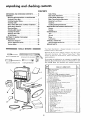
unpacking and checking contents
CONTENTS
UNPACKING
AND
ASSEMBLY
CHECKING
Mounting
Band Saw/Sander
Craftsman
Floor
Installing
Sawdust
Installing
Table
Motor
CONTENTS
.....
...........................
Base ...................
Elbow .................
.......................
Rotation
Table Tilting .........................
Blade Guide Adjustment
Installation..
..................
Mounting
Motor
Attaching
Belt Guards ...................
7
Blade Thrust
7
Guide Bar Lock Screw
8
Guide Bar ...........................
9
Installing
10
......................
BASIC
Tires
16
General
Adjustment
BAND
Diagrams
Tension Adjustment
18
...................
18
Knob ................
TOOLS
18
NEEDED
............................
........................
22
22
.............................
TROUBLE
22
..........................
SHOOTING
Recommended
REPAIR
22
............................
Lubrication
18
Tension Scales ........................
21
..............................
Motor
.........................
......
21
16
SAW/SANDER
19
OPERATION
MAINTENANCE
The Table ....................
YOUR
SAW/SANDER
.............
21
Adjusting
KNOW
19
Attachment
Sanding
12
TO
18
Sawing .............................
....................
GETTING
18
..................
11
The Blade
Switch ........................
18
...........
10
Installing
On-0ff
18
................
Bearing Adjustment
Sanding
BAND
18
.................
Lateral Guide Adjustment
on Recommended
Pulley Belt Guard and Motor
Check Motor
6
7
PARTS
22
...................
23
Accessories ................
23
........................
24
Your Band Saw/Sander
(without
motor or floor
is shipped
base).
complete
in one carton
Separate
all parts from packing materials
and check each
item with
illustration
and "Table
of Loose Parts." Make
certain
all items
packing material.
MEDIUM
SCREWDRIVER
SCREWDRtVE
1\
COMBINATION
R
7/16
INCH
SQUARE
WRENCH
for,
before
discarding
any
If any parts are missing, do not attempt
to assemble the
band saw, plug in the power cord or turn the switch on until
the
missing
parts are obtained
and installed
correctly.
:,..eyj;K
]
TABLE OF LOOSE PARTS
No.I
1 Basic Saw Assembly
.................
2
Owner's
3
Saw
Qty.
t
Manual
Table
1
......................
!
4
1/2x 52-1n.V-Bek ..................
1/2 x 43-1n. V-Belt (Supplied in Canada) ......
5
Carton
Support
containing
Belt
Bracket,
Guard,
three
Clips
Belt-Guard
!
1
Support,
and three
Self
Tapping Screws
6
7
8
9
1/2-h%
1/4-1n.
Sanding
2
1
1
1
Belt
Band=Saw Blade ...............
Sawdust Elbow ...................
Two Bags containing
the following
items:
Set Screw Wrench, 1/8"
. ............
Set Screw Wrench, 5/32"
. ...........
Set Screw Wrench, 3/16"
. ...........
Flat
Washer,
t-!/8" diameter ...........
Trunnion Looknut .................
Pa_lHd, Mach. Screw, Self Tap, 10-32x3/8".
Pan Hd. Mach. Screw, Self Tap, 8-32x 1/4"
Tube Clamp ....................
Rubber Gasket (stripl ...............
1
1
1
1
1
2
2
1
1
1
1
1
1
'_
!
Alignment
Plate
....
Motor
Pulley,
2-I/2",
!
Soc-Hd,
Setscrew,
Flat
Pt.
5/16-18x3/8"
Flat-Hd. Macb. Screw, 6-32x7/16".
He× Nut, 6-32 ...................
Spilt
Lockwasher,
No. 6 ..............
Tilt Pointer ....................
Wing
Banding
Screw
.......................
Platen
". .............
...............
..................
Cord Clamp
Table Insert
Tilt Lock Handle (Wrench)
Spacer .......................
Blade Tension Knob
..............
SMALL
are accounted
Switch
Key
....................
....
. ....
.
........
.....
1
1
!
1
1
1
1
2
assembly
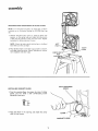
MOUNTING
NOTE:
mounted
Set.
BAND
For
SAW/SANDER
illustrative
purposes,
on the Craftsman
Catalog
ON FLOOR
the
Band
STAND
Saw is shown
No. 9-22236
Steel
Leg
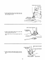
1. Remove
the Band Saw cover by applying
gentle side
pressure on the spring tabs and release [he top portion
of the cover by pulling it away from the frame. Repeat
procedure for bottom
portion
of cover.
NOTE:
Check
the bolts
which
hold the feet to the Band
Saw. Make sure they are tight.
LEFT
FOOT'_
RIGHT
2. Place the Band Saw on the Steel Legs, position
and align mounting
holes. Mount
according
tions supplied
with Steel Legs.
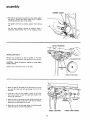
INSTALLING
as shown,
to instruc-
CHECK
FOR
SELF-THREADING
SCREW
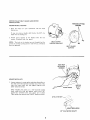
SAWDUST ELBOW
1. Find the sawdust elbow,
gasket, and two
10-32
among the loose parts.
2. Place the elbow in the
with the two screws.
FOOT
the clamp, the strip of rubber
x 3/8"
self-threading
screws
opening,
and
attach
the
clamp
SAWDUST ELBOW
assembly
RUBBER GASKET
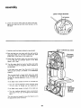
3. Peel off the protective covering from the rubber gasket
and stick it around the clamp. Make sure it extends
a little
beyond each end of the clamp.
(
The gasket
out.
will
help
to prevent
For the most efficient
Craftsman
Home-n-Shop
sawdust
from
leaking
\
removal of sawdust,
attach
a
Vac to the sawdust
elbow.
TABLETRUNNION
INSTALLING
TABLE
Remove the protective
oiT that is applied to the table.
Use any ordinary
household
type grease and spot remover.
CAUTION:
Never
volatile solvents.
Apply
use gasoline,
a coat of automobile
naptha
or similar
_N PIN
highly
wax to the table.
PIN
TABLE LOCK BOLT
1. Place the table on the band saw so that
pins and
trunnion.
the
table
lock
bolt
go through
the two
trunnion
the slot
2. Find the 1-1/8"
dia. flat washer, a sleeve 11/16"
the trunnion
lock nut and the table lock handle
among
the
in the
_NUT
long,
from
loose parts.
3. Hold the head of the table lock bolt inside the band saw
with your left hand and put the 1-1/'8" dia. flat washer,
the sleeve, and the handle on the bolt,
4, Screw the nut on the bolt and tighten it with the handle
while the table is in a horizontal position.
TABLE
LOCK
BOLT
TABLE
LOCK
HANDLE
MOTOR
PULLEY
INSTAL
BELT
GUARD
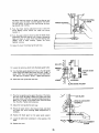
MOUNTING
1. Place
facing
BELT
MOTOR
TH READ CUTTI NG
SCREWS
GUARD
the motor
you,
on
your
If you are using a double
shaft must be facing you.
2. Attach
screws,
NOTE:
AND
LATION
guard
support
furnished
with
The holes
screws are "thread
they are tightened.
in the
cutting
workbench
shaft
with
motor,
to the bracket
the guard,
bracket
screws"
are not
the
the
5/8"
dia.
with
the
two
threaded,
and will
shaft
cut
but the
a thread
as
BELT
SUPPORT
GUARD
BRACKET
BELT GUARD
SUPPORT
5/32 I NCH
SETSCREW
WRENCH
\
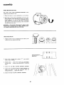
MOUNTING
PULLEY
1, Loosen setscrew in motor pulley and place the pulley on
the shaft with
the hub flush with the end of the shaft,
insert the motor
shaft
key and tighten
setscrew with
5/32"
setscrew wrench.
MOTOR
FLUSH
SHAFT
HERE
KEY
When installing
the pulley
on a 1/2" diameter
motor
shaft,
make sure that
the adapter
sleeve and 3/16"
square key furnished
with
your motor
are in place.
Then tighten the setscrew with a 5/32"
setscrew wrench.
3/16
x 3/16
KEY
,._
\
ADAPTER
1/2"
SLEEVE
DIA. MOTOR SHAFT
assembly
CHECK
MOTOR
ROTATION
The
motor
must rotate
viewed from the PULLEY
1. Place
the
motor
2. Stand
clear
of
on
COUNTERCLOCKWISE
end.
your
the motor
workbench
and plug
perly grounded
outlet (See
of the pulley.
If it is not
WISE, REMOVE
the plug
the rotation
of the motor
furnished
with the motor.
or on
the cord
when
the
floor.
into a pro-
page 4). Notice the rotation
turning
COUNTERCLOCKfrom the outlet, and change
according
to the instructions
WARNING:
FOR YOUR OWN SAFETY, MAKE SURE
PLUG IS NOT CONNECTED TO POWER SOURCE OUTLET WHEN CHANGING MOTOR ROTATION.
MOUNTING
MOTOR
1. Find four 5/16"-18
x 1"' carriage bolts, flat washers, lockwashers and nuts supplied with base.
LJ
MOTOR
BRACKET
2. Insert
motor
bolts through
holes
mount
bracket.
3. Attach
motor
on each bolt
them.
4.
Loosen
the
5. Loosen
rotate
the
the
facing
6. Tighten
"X'"
from
_.._._/
_
-[
O
behind
. . . place a flat washer and a Iockwasher
. . . screw on nuts but DON'T
TIGHTEN
two
BELT
GUARD
SUPPORT
SCREWS.
two MOTOR
BASE CLAMP
SCREWS
motor
so that
the ventilation
holes
downward
the
marked
MOUNT
BELT
. . . tighten
GUARD
the
\
screws.
SUPPORT
\
\
and
are
SCREWS.
10
__--__GUARD
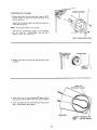
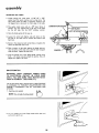
ATTACHING
BELT
SUPPORT
GUARDS
1. Remove the pulley from the band saw, using the 5/32"
setscrew wrench to loosen the screw. Be careful not to
lose the shaft
Attach
nished
NOTE:
key.
the belt guard support
with the guard.
The support
bracket
with
the three
screws fur-
is not required.
The holes for attaching
the support
but the screws are "self-threading"
thread
as they
are screwed
in.
are not threaded,
and will cut a
/
SELF-THREADING
FLUSH
2. Replace the
the shaft.
pulley
with
the
hub flush
with
SCREW
HERE
the end of
LONG TAB
POINTED THIS WAY
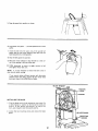
3.
Install
long
three
tabs
clips
pointing
on the belt guard 90 ° apart with the
AWAY
from
the
round
opening,
4. Insert one looped end of belt all the way into guard so
that it will be below motor pulley.
/
OPEN
END
SPRING
CLIPS
(SET 90 ° APART)
11
5. Snap the guard
6.
Look down
pulley.
into
position
into guard..,
7. Insert the belt
guard, and out
band saw pulley
as shown.
pull
belt upwards
motor
into the open end of the second belt
the round opening.
Place belt onto the
by rotating
pulley.
8. Snap the belt guard
into position.
9. Move the motor sideways so that the belt
ter of the opening in the top of the base.
10. PUSH downward
and tighten motor
NOTE:
It is only
does not slip while
onto
on motor
bott nuts.
necessary
running.
to
apply
to tension
is in the cen-
tension
the
to
belt
belt so that
it
If you cannot obtain sufficient
tension with the motor
pushed all the way down, remove the four motor
bolts
and insert them in the LOWER set of holes.
TENSION
..........
STUD
POINTER
INSTALLING
1. Find
a dab
screw
turns,
2. Loosen
guard.
the
of
it
just
THE BLADE
blade tension knob among the loose parts. Put
grease or vaseline on the end of the knob and
on the tension stud. Screw it on only a few
enough to start moving the pointer.
the two
mounting
screws
and remove
the
blade
GUARD
MOUNTING
SCREWS
12
GUIDE BAR LOCK SCREW
GUIDE BAR
3. Loosen the guide bar lock screw and position
guide assembly approximately
three inches
table and tighten
the knob,
the upper
above the
UPPER BLADE
GUI DE ASSEMBLY
UPPER THRUST
BEARING
1/8" SETSCREW
WRENCH --_.-,
4, Loosen the two setscrews which lock the upper blade
guidesand separate them about 1/B".
Do that same thing to the lower guides beneath
table.
the
SETSCREWS
BLADE GUIDE
I
UPPER THRUST
BEARING
THRUST BEARING
ADJ. KNOB
\
5. Loosen the setscrew which locks the upper thrust bearing and turn knob until the thrust bearing is all the way
back.
1/8" SETSCREW WRENCH
/
BLADE GUIDE
13
assembly
LOWER THRUST BEARING
6. Loosen the setscrew which locks the lower thrust bearing and turn the knob until the thrust bearing is all the
way back.
7. Carefully uncoil the blade, holding it at arms length.
ADJ. KNOB
8. Place the blade over the wheels with the teeth ,pointing
downwards. Make sure the blade is between the blade
guides and is in the center of the rubber tires,:
TRACKING
rMENT
SCREW
9. Screw down the tension knob until the pointer points
to 1/4. This will put sufficient tension on the blade
which is 1/4" wide.
10. Turn the upper wheel by hand a few times and notice
if the blade remains in the approx, center of the tire on
the top wheel.
If the blade moves away from the center of the wheel
while you are turning it, the blade is not TRACKING
properly.
The top wheel shaft is hinged which allows the wheel
to be tilted so that the blade can be TRACKED. 8y
turning the tracking adjustment screw, the wheel will
be tilted.
If the blade moves toward the front of the band saw:
a. Turn the tracking adjustment screw clockwise about
1/4 of a turn, as though you were tightening
it.
BLADE
CENTERED
ON TIRES
OF BOTH
WHEELS
If the blade moves toward the back of the band saw:
a. Turn the tracking adjustment screw counterclockwise about 1/4 of a turn as though you were loosen_ngit.
Turn the screw just enough to cause the
the approximate
center of the tire.
blade to run in
14
The thrust
will rotate
bearings support
the blade from the rear and
when the blade is pushed against them while
you are cutting.
ings should stop
!1.
Turn
the
thrust
touches
As soon as you
rotating.
thrust
bearing
it.
bearing
moves
stop
adjustment
toward
cutting,
knob
the
the
bear-
so that
blade
and
rHRUST BEARING
ADJ. KNOB
THRUST BEARING
the
almost
12. TL_rn the upper wheel by hand so that the blade moves
downward,
move the bearing until it barely touches the
blade ;and starts to rotate. Now move the bearing back
slightly,
until
it stops rotating.
Tighten
the thrust
bearing
setscrew.
13. Adjust
the lower
thrust
bearing the same way.
GU
14.
Loosen
the
setscrew
which
locks
the blade guide holder.
15. Turn the blade guide adjustment knob, so that the guides
move toward the blade, Move them until the "ledge" is
about 1/32" from the deepest part of the blade teeth.
This deep part is called a "gullet". Tighten the setscrew.
16. Adjust
the
lower
guides the same way.
APPROX.
1/32"
BLADE GUIDE
KNOB
SETSCREW
BLADE GUIDE HOLDER
17. Press the two guides evenly against the sides of the blade,
but don't pinch the blade. Release the guides and rotate
the upper wheel a little bit, moving the blade downward.
Make sure one guide is not farther
away from the blade
than the other. Tighten
both setscrews.
18. Adjust
the lower
19,
Rotate the
the guides
necessary.
20.
Replace
21.
Locate
table.
22,
Replace
the
guides
UPPER BLADE GUIDE
ASSEMBLY
the same way.
upper wheel a few times by hand, and check
and thrust
bearings. Make readjustments
if
blade
the table
the cover.
guard on
the
upper
guide
support.
insert and place it in the opening
SETSCREWS,
m ti_e
ALIGNMENT
SCREW
assembly
ADJUSTING
THE TABLE
I. Locate among the loose parts a 5/16"-18"
x 3/8"
socket head flat point setscrew and a wing screw. The
wing screw keeps the table in alignment. Screw it into
the tapped hole underneath the front edge of the table.
2. The
socket
partially
on the
head
into
left
screw
acts • as a 90 ° stop.
the tapped hole in the top of
side. Use the 5/32"
setscrew
Screw
COMBI NATI ON SQUARE
it
the table
wrench.
5/32"' SETSCREW WRENCH
3.
Raise the blade guides all the way up.
4.
Loosen the
left side of
table lock slightly
and push down on the
the table until it touches the frame of the
band saw.
5. Screw
frame,
in the stop screw and notice
the table will start to tilt.
that
as it touches
the
6. Place a square on the table against the blade and continue to screw in the stop screw until the table is square
with the blade. Tighten the table lock.
7.
Find
8-32
the pointer
and a pan head
x 1/4 inches long and attach
degrees and tighten
thread cutting
screw
the pointer.
Set at 0
the screw.
ON-OFF SWITCH
WARNING:
DON'T CONNECT
POWER CORD
TO ELECTRICAL
OUTLET
IN YOUR
SHOP
UNTIL YOU ARE SURE THAT MOTOR ROTA"rlON IS CORRECT. (SEE PAGE 11).
The On-Off Switch has a locking
feature. THIS FEATURE
IS INTENDED
TO PREVENT
UNAUTHORIZED
AND
POSSIBLY
HAZARDOUS
USE
BY CHILDREN
AND
OTHERS.
1. Insert key into switch.
NOTE:
I
I
I
Key is made of yellow
i
2. To turn machine
pull end of switch
I
plastic
I
on, insert finger
out.
under
switch
lever and
16
3. To turn
Never
machine
OFF
...
leave the machine
to a complete
PUSH
unattended
lever in.
until
it has come
stop.
4. To lock switch in OFF position . . . hold switch IN
with one hand , . . REMOVE key with other hand.
WARNING"
FOR YOUR OWN SAFETY, ALWAYS LOCK THE SWITCH "OFF"
WHEN
MACHINE
IS NOT IN USE ... REMOVE KEY
AND KEEP IT IN A SAFE PLACE...
ALSO
• . . IN THE EVENT OF A POWER FAILURE
(ALL OF YOUR
LIGHTS GO OUT) TURN
SWITCH OFF... LOCK ITAND REMOVE THE
KEY. THIS WILL PREVENT THE MACHINE
FROM STARTING
UP AGAIN
WHEN THE
POWER COMES BACK ON•
INSTALLING
1. Find the
threading
as shown.
MOTOR
pULL
CORD CLAMP
cord clamp and one 8-32 x 3/8 pan hd. self
screw and install below the motor-cord
outlet
CORD
CLAMP
17
getting to know your band saw/sander
2
8
TENSION ADJUSTING KNOB-_
COVER RETAINING CLIP
(4-Used)
1
GUIDE BAR LOCK SCREW
"X.
3
\
ADJUSTMENT
DIAGRAMS
TENSION SCALE'
(Inside)
ON-OFF
GUARD
OUTLET
WORK LIGHT
GUIDE BAR
"7 THRUST
BEARING
COVER
ADJ. KNOB
(Lower Knob
Not Shown)
TABLE
TILT SCALE
SAWDUST ELBOW
TI LT LOCK
HANDLE
TILT PC
LEFT FOOT /
"_"'--R
IGHT FOOT
PULLEY
BLADE GUIDE
' ADJ. KNOB
(Lower Knob NOt Shown)
FRONT
BA CK
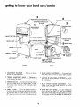
1. ADJUSTMENT DIAGRAMS . . . Help you to become
familiar with the adjustments.
2. TENSION ADJUSTMENT
KNOB ..... Tightening the
knob will increase the tension on the blade. Loosening
it will decrease the tension.
3. TENSION
SCALES...
The fractional
markings indicate
the correct blade tension for various widths of blades.
For example,
when installing a 1/4" wide blade, tighten
the tension
marking.
knob
until
the pointer
is pointing
to the 1/4
4. TABLE
TILTING
...
Loosen the table lock handle, tilt
the table to the desired angle and tighten the lock handle
o
To return the table to the 90
position,
tilt it until the
90 ° stop screw rests on the frame, then tighten the lock
handle.
5.
BLADE
GUIDE
ADJUSTMENT
moves the guides in or out for
. , . Turning the knob
various widths of blades.
6,
LATERAL BLADE GUIDE ADJUSTMENT
. . . Th_
guides can be adjusted sideways and locked in position
by the setscrews.
7.
BLADE THRUST BEARING ADJUSTMENT...
Turning the knob moves the thrust bearings in or out for
various widths of blades.
8. GUIDE BAR LOCK SCREW . ; The upper blade guides
should not be more than 1/4" above your workpiece
while cutting. Always adjust the guides before turning on
the band saw and lock the guide bar by tightening the
thumb screw.
18
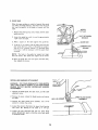
9. GUIDE
BAR
When the upper guides are raised or lowered, they must
not deflect the blade sideways. This means that the guide
bar must
table.
be parallel
to the
blade,
or square
with
the
SCREW
1. Remove
the blade
guide assembly.
guard,
cover,
the guide bar until
from the table.
blade,
2.
Lower
1-3/4,
3.
Hold
4.
If the bar is not square with the table, lock guide bar
and Iooseh the four screws in the guide bar support.
Use the 3/16"
setscrew wrench. To reach the lower
a square
left screw,
outward,
on
it will
the
the
table
end
and the upper
is approximately
against
be necessary
the
to tilt
guide
the upper
wheel
NOTE:
The holes in the guide bar support
than the screws. This allows
the support
to
are larger
be moved.
5. Move the guide bar until
then tighten the screws.
the
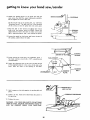
INSTALLING
SANDING
it is square
with
lljou,o.o..
bar.
table,
ATTACHMENT
WARNING:
FOR YOUR OWN SAFETY, TURN SWITCH
"OFF"
AND ALWAYS REMOVE PLUG FROM POWER
SOURCE OUTLET BEFORE INSTALLING
SANDING
ATTACHMENT.
1. Remove the blade guard,
alignment
screw.
2. Remove the cover,
the blade.
the
table
release the
blade tension
3. Remove the upper blade guide
wrench to remove the screw.
4.
Loosen the setscrew that
and
move
the
bearing
5. Loosen
the
two
aPart
assembly.
and the table
and remove
HEX.
Use a7/16""
locks the lower thrust bearing,
as far back
as it will
go.
setscrews
guides. Spread them
is inside the holder,
insert,
that
lock
so that
the
the
lower
blade
end of each guide
19
HD. SCREW
_
ASSEMBLY
getting to know your band saw/sander
6. Attach
the sanding platen to the guide bar with the
same screw that held the upper blade guide assembly.
Do not tighten the screw at this time.
On the smooth side of the sanding belt, you will find a
"directional
arrow",
The belt must run in the direction
of
this
arrow
so that
the
splice
does not
7. Place the belt on the wheels and
knob until
the pointer
points
to
upper wheel by hand a few times to
belt is tracking
properly
and is not
8. Loosen the
the sanding
come
q;i__
apart.
GUIDE
tighten
the tension
SAND.
Rotate
the
make sure that the
rubbing the guides.
guide bar lock screw and
platen below the table.
lower
-f
IJl"--SANDING
Itl
the end of
JCENTER
SANDING
PLATEN
OF SLOT
I
9. Locate among the loose parts, the alignment
plate, a
flat head machine
screw 6-32 x 7/16", a small hex nut
TABLE
and lockwasher.
10, Attach
_.
the alignment
of the alignment
insert.
Place
BAR
plate
the
plate to the
insert
is in the center
insert
in
the
so that
the end
of the slot
opening
in the
/
SCREW
in the
(--_.-.,
table.
_3_C:::::::::
L/_'k \
LOCKWASHER
i
_"
I
_
/
/
_.__
ALIGNMENT
_SANDtNG
BELT
PLATE
SANDING BELT
AND PLATEN
11. Hold a square
platen.
on the table
12. Tighten
the hex,
the guide bar.
13,
Replace
head
against
screw
which
the sanding
holds
belt and
the platen
to
COMBINATION
the cover.
WARNING:
FOR YOUR OWN SAFETY,
DO tklOTSAND
IRON OR STEEL BECAUSE
THE SPARKS
COULD
IGNITE
THE
SAWDUST
INSIDE
YOUR
BAND
SAW.
2O
SQUARE
basic band saw/sander
BASIC BAND SAW/SANDER
operation
OPERATION
A band saw is basically a "curve cutting" machine. It differs
from a saw in two respects. It is capable of cutting thicker
material
and it cuts faster. Unlike
a saw, it is not capable
of doing inside cutting.
Your Craftsman
Band Saw/Sander
is not only capable of
the usual band saw operations,
but it can be converted
into
a sander as well. You can finish wood, certain compositions
and plastics
and non-ferrous
metals.
SAWING
1. Adjust the
workpiece.
upper
guides
not
more than
1/4"
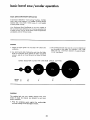
3. The smallest
above your
diameter
that can be cut out is determined
by the width
of the blade. For example,
a 1/4"
wide
blade will cut a minimum
diameter
of approximately
1-1/2".
2. Use both hands while feeding the work into the blade.
Hold the workpiece
firmly
against the table. Use gentle
pressure, and do not force the work, but allow the blade
to cut.
BLADE
SELECTION
GUIDE
FOR
MINIMUM
CIRCLE
BLADE
1"
3"
1"
3"
SIZE
_
_
3.
8
SANDING
The sanding belt cuts very rapidly. Practice with some
scraps of wood first before you attempt to sand your
actual workpiece.
1. Press the workpiece
gently against
the sanding
and keep moving it until the edge is smooth.
belt,
21
(See Chart)
CUTTING
maintenance
WARNING:
FOR YOUR
OWN SAFETY,
TURN SWITCH
"OFF"
AND REMOVE
PLUG FROM POWER
SOURCE
OUTLET
BEFORE
MAINTAINING
OR LUBRICATING
YOUR
BAND SAW.
MOTOR
ON-OFF
SWITCH
TIRES
C
A
BLACK
Pitch and sawdust that accumulate
on the tires should be
removed with a stiff brush or scraped off with a piece of
wood.
Do not use a sharp knife or any kind of solvent.
When the tires become worn they should
replacing
the tires, stretch them around
not glue them on.
be replaced. When
the wheels but do
GENERAL
_"=
Keep your
Remove
Band
Saw/Sander
the sawdust
from
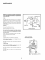
WIRING
the inside.
DIAGRAM
Do not allow pitch to accumulate
on the table, the insert,
the guides or the thrust bearings. Clean them with Craftsman Gum and Pitch Remover. CAUTION:
Do not immerse
the thrust
bearings.
Apply a thin coat of automobile-type
wax on the table
that the wood slides easily while cutting.
so
MOTOR
Frequently
blow
out any sawdust
from
If the power cord is worn or cut,
have it replaced immediately.
For motor
the motor.
maintenance,
follow
WHEEL NOT SHOWN
FOR PICTURE CLARITY
the motor.
or damaged
instructions
in any
furnished
way,
with
LUBRICATION
All of the BALL
BEARINGS
are packed with
factory.
They require no further
lubrication.
For motor
the motor.
lubrication,
Periodically
guide rods.
apply
follow
instructions
grease at the
furnished
with
GUIDE
RODS
/
a few
GROUND
clean.
drops
of oil
to the
upper
wheel
22
OUTLET
trouble shooting
WARNING: FOR YOUR OWN SAFETY, TURN SWITCH
"OFF"
AND REMOVE PLUG FROM POWER SOURCE
OUTLET BEFORE TROUBLE SHOOTING YOUR BAND
SAW/SANDE R.
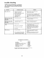
TROUBLE
Motor will not run.
PROBABLE
1. Defective
Defective
REMEDY
CAUSE
On-Off switch,
switch cord.
1. Replace defective
Band Saw/Sander
Defective
switch box receptacle.
2. Motor protector
open,
(only if your motor is
equipped
with an
overload protector).
Other cause.
Blade does not run in the
1. Not
tracking
1. Lower wheel
correctly
on
Band Saw slowsdown when
cutting.
!.
Belt too
2. Motor
properly.
1. Adjust tracking,
see Assembly
'qnstalling
the Blade."
not positioned
shaft.
1. Reposition
the wheel, see Assembly
Section,
"lnstalling
the Blade."
3. Cutting
4. Dull
Blades breaking.
loose.
pivots
using
2. Consult Sears Service. Any attempt
to repair
this motor may create a HAZARD
unless
repair is done by a qualified
service technician.
Repair service is available at your nearest Sears
Store.
approximate
center of the
upper wheel.
Blade does not run in the
approximate center of the
lower wheel.
parts before
again.
in motor
Section,
1. Adjust belt tension, see Assembly
Section,
"Attaching
Belt Guards."
2. Tighten motor base clamp screws. See
Assembly
Section, "Motor
Installation"
3. Stop feeding, and back up the material
slightly,
until the band saw speeds up.
4. Replace blade.
base.
too small a radius.
blade.
1, Too much tension.
!. Adjust tension. See Getting To Know
Your Band Saw!Sander,
"3 Tension
Scales.'"
2. Kink in blade caused by cutting
too small a radius or turning
the
material
too fast when cutting.
2. Use correct cutting technique.
See Basic
Band Saw/Sander
Operation
Section,
RECOMMENDED
ACCESSORIES
Item
Floor
Base
Cat. No,
....................
9-22213
Miter Gauge ............
".......
Hold-Down
Clamp For Miter Gauge ....
Stop-Rods
For Miter Gauge .........
Rip Fence .....................
Blades and Sanding Belts ...........
Steel Leg Set ..................
The
above
available
recommended
at the
time
accessories
this
manual
23
9-29929
9-29928
9-29924
9-23432
See Catalog
9-22236
are current
was printed.
and were
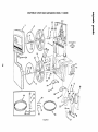
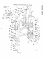
CRAFTSMAN
12-INCH
BAND SAW/SANDER,
MODEL
"!
113.24350
-8
mo
10
"1
"!0
8
2
6
/
SEE FIGURE
FOR
EXPLODED
VIEW
56
2
29
15
32
\
\
!
11 27 I
14
11
33
I
/
/
/
/
44
_
/
39
!!/,o
/
/
38
37
43 "_®
36
FIGURE
I
/
/
/
/
/
/"
1
17
18
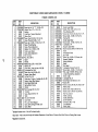
WHEN
ORDERING
CRAFTSMAN
12-INCH BAND SAW/SANDER,
REPAIR
ALWAYS
PARTS,
GIVE
THE
FOLLOWING
1. THE
PART
NUMBER
3. THE
MODEL
2. THE
PART
NAME
4. THE
NAME
MODEL
113.24350
INFORMATION
NUMBER
OF ITEM-
AS SHOWN
ON THE
LIST:
113.243_0
12-1NCHBANDSAW/SANDER
Always order by Part Number - not by Key Number
FIGURE
KEY
PART
NO.
O1
1
2
3
4
5
6
7
8
69069
41815
38524
37158
41711
STD315228
69028
41812
9
60256
10
11
12
13
14
15
69085
60251
38884
STD601105
30789
STD503105
16
38450
17
18
19
19
20
60255
60252
STD304430
STD304520
30646
21
22
60254
60253
*Standard
tStock
Hardware
Item -
NOTE:
Frame with Trim
Screw, Self-Locking
Ring, Retaining 5/8
Washer, Spring
Bearing, Ball
Wheel, Upper Drive
Ring Internal
Retaining
1-3/8
Key, Switch
Clip
Bearing, Ball
Ring, Internal
Retaining
1-11/16
*Screw Type 23, 10-32 x 1/2, Pan Hd.
Key, Square 3/16 x 1-1/4
*Screw, Set, 5/16-18 x 1/2, Soc. Hd.,
Cup Pt.
tPulley,
1/2 V Groove,
5" x 5/8
Bore, Keyed with Set Screw
Clip, "S"
Guard, Belt
_ tBelt, V Type, 1/2 x 43
tBelt "'V" Type, 1/2 x 52
tPulley,
1/2 V Groove, 2-1/2"
Bore, Keyed with Set Screw
Bracket, Support
Support,
Belt Guard
Item -
May Be Purchased
and handling
these items
oSupplied
Cover,
Tire
May be secured
Shipping
KEY
NO.
DESCRIPTION
NO.
1 PARTS LIST
through
DESCRIPTION
23
24
25
26
453068
*Screw, 5/16-18 x 3/4, Sems, Hex, Hd.
69084
Foot, Frame
STD5410311 *Nut, Square, 5/16-18
STD522503 *Screw Mach., 1/4-20 x 3/8, Truss
27
28
29
30
31
32
33
34
35
36
37
38
39
40
41
42
43
44
69023
65013
69004
STD601103
69078
69059
69O58
69025
60272
37887
60096
37911
69062
133427
69005
STD551106
STD541Q06
69037
69087
69086
69088
Hd., Slotted.
Spacer, Bearing
El bow
Clamp, Tube
*Screw, Mach., 10-32 x 3/8, Pan Hd.
Gasket, Foam
Wheel, Lower Drive
Shaft, Lower Wheel
Lens
fBlade, Band Saw, 1/4 x 80
tWrench,
Hex., "L",
I/8
tWrench,
Hex., "'L", 5/32
tWrench,
Hex., "'L", 3/16
Platen, Sanding
*Screw, Mach., 6-32 x 7/16, Flat Hd.
Plate, Sanding Alignment
*:Loekwasher,
No. 6
*Nut, Hex., 6-32
tBelt, Sanding, 1/2 x 80
Owner's Manual (Not Illustrated)
Bag Asm. Loose Parts (Not Illustrated)
Bag Asm. Loose Parts (Not Illustrated)
Locally.
the Hardware
Department
charges for standard hardware
by mail uneconomical.
in Canada Only,
x 5/8
PART
NO.
To avoid
shipping
of most Sears or Simpsons-Sears
items (identified
and handling
Retail
by *) such as nuts, screws,
charges,
you may obtain
Stores or Catalog
Order
Houses.
washers, etc., make buying
most of these locally.
\
\
\
t
,+
CRAFTSMAN
12-INCH
BAND
FIGURE
1o
_4
'KEY
NO.
PART
NO.
1
2
3
4
5
6
7
8
9
10
11
12
13
14
15
16
17
18
19
2O
21
22
23
24
25
26
27
28
29
3O
31
32
33
34
35
36
37
38
STD522503
STD55105(_
63266
69031
3O613
STD600802
60321
STD502502
69042
69046
69047
69048
69049
69021
STD541037
69077
69072
STD551037
38724
69070
STD551131
9416187'
69029
STD572507
69068
41426
69022
69019
69089
STD533725
69057
62122
69074
ST D571203
69063
69024
60190
69039
DESCRIPTION
• Screw Hex Hd, Ty "T", 1/4-20 x 3/8
Washer, Plain, 1/2 x 1-1/4 x 1/8,
Bushing
Knob Assy., Tension Adjustment
Clamp, Cord
• Screw, Type 23, 8-32 x 1/4, Pan Hd.
Screw, Thumb 5/16-18 x I-1/2
• Screw, Set, 1/4-20 x 1/4 Soc. Hd., FI. Pt.
Sleeve, Thrust Bearing
Screw, Thrust Adjustment
Washer, 1/4 x 1-13/32 x 1/16
Knob, Lower Guide
Screw, Guide Adjustment
Pin, Trunnion
• Nut, Hex. 3/8-16
Spacer
Wrench
• Washer, Plain, 3/8 x 1-1/8 x 7/64
Pointer, Tilt.
Frame Assy., (Incl. Key Nos. 14 & 36)
• Lockwasher Ext. 5/16
• SCrew, Hex. Hd. 5/16-18 x 3/4
Bumper, Upper Wheel
Pin Roll 1/4 x 3/4
Guide Assy., Fulcrum (includes Key No. 24)
Bracket, Upper Wheel Support
Rod, Upper Wheel Guide
Spring, Wheel Tension
Pointer
• Bolt, Carriage, 3/8-16 x 2-1/2
Trunnion
Screw, Wing 5/16-18 x 1/2
Table
Pin, Roll 1/8x 5/16
Insert Table
Pin, Lower Guide Support
Screw, Self-Locking, 5/16-18 x 3/8
Guide, Blade
*Standard Hardware Item-
SAW/SANDER,
MODEL
113.24350
2 PARTS LIST
KEY
NO.
PART
NO.
39
40
41
42
43
44
45
46
47
48
49
50
51
52
53
54
55
56
57
58
59
6O
69045
STD551031
STD581031
STD502505
STD512505
STD315505
69038
STD522508
STD551125
69041
STD601103
69044
69043
69035
216278
69036
69034
69012
30682
STD551225
STD522512
STD372252
61
62
63
64
65
66
67
68
69
70
71
72
73
74
75
69014
STD551208
STD510802
69066
STD60O803
69009
60287
447845
69010
60257
69082
69027
STD375006
69026
37875
DESCRI PTI ON
Guide, Lower Blade
*Washer, Plain, 5/16 x 9/16 x 1_'16
Ring, Retaining,
5/16
*Screw, Set, 1/4-20 x 3/4, Soc. Hd., FI. Pt.
*Screw, Mach., 1/4-20 x 1/2, Pan Hd.
Bearing, Ball
Guide, Upper Blade
*Screw, Mach., 1/4-20 x 7/8, Hex. Hd.
* Lockwasher,
1/4
Support,
Upper Blade
*Screw, Type 23, 10-32 x 5/16, Pan Hd.
Guard
Knob Upper Guide
Bar, Guide
*Screw, Cap, 1/4-20 x 1/2, Socket, Hd.
Support,
Guide Bar
Spring, Guide Bar
Spacer
* Nut, Speed
*Lockwasher,
External Tooth 1/4
*Screw, Mach., 1/4-20 x 1-1/4, Pan Hd.
*Bulb, Light 115/125V,
25 Watt, Dbl.
contact, Bayonet Base, Appliance
Socket, Light
* Lockwasher
No. 8
* Screw Mach., Pan Hd. 8-32 x 1/4
• Guard, Wire
, Screw,
Relief,
*Screw,
*Screw,
Type 23, Pan Hd., No. 8-32 x 3/8"
Strain
Nylon,
6-32 x 3/8, Pan Hd.
Type T, 1/4-20 x 1/2, Pan Hd.
Box Assy., Switch
Switch, Locking
Gasket, Switch Box
Outlet Assembly
*Connector,
Wire, 14-18
Cord Assembly
Relief, Strain
May Be Purchased Locally.
_Stock Item - May be secured through the Hardware Department of most Searsor Simpsons-SearsRetail Stores or Catalog Order Houses.
=Supplied in Canada only.
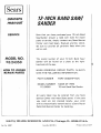
]Sears I
12-INCH BAND SAW/
SANDER
owners
manual
SERVICE
Now
that
you
Saw/Sander
parts
should
or service,
Center
MODEL NO.
113.24350
have purchased
and
a need
simply
most
Sears,
all
pertinent
The
number
of
your
WHEN
ORDERING
GIVE
THE
MODEL
FOLLOWING
NUMBER
113.24350
All
parts
Service
you
will
listed
may
and
are
Parts Distribution
Part No.
69087
by
SEARS,
ROEBUCK
AND
Form
CO.,
you
Band
Saw/
the
right-
at
ALWAYS
PART
DESCRIPTION
NAME
OF ITEM
be
Band Saw/Sander
ordered
Center
Chicago,
from
Sears stores.
locally,
transmitted
No. SP4121-5
stores.
when
PARTS,
stocked
be electronically
repair
INFORMATION:
most
not
facts
a plate
12-Inch
Center
need
on
Band
for
and Co.
12-Inch
REPAIR
NUMBER
exist
Roebuck
provide
model
12-Inch
any Sears Service
Be sure to
call or visit.
PART
Sold
ever
contact
Sander
will
be found
hand side of the saw.
HOW TO ORDER
REPAIR PARTS
your
any
Sears
If the
parts
your
order
to a Sears Repair
for handling.
IL.
60684
U.S.A.
Printed
in U.S.A.
12/77