1
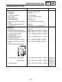
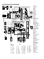
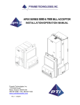
XV17AS(C)
XV17ASS(C)
XV17ATS(C)
SUPPLEMENTARY
SERVICE MANUAL
LIT-11616-17-09
4WM-28197-E1
FOREWORD
This Supplementary Service Manual has been prepared to introduce new service and data for the
XV17AS(C)/XV17ASS(C)/XV17ATS(C). For complete service information procedures it is necessary to use this Supplementary Service Manual together with the following manual.
XV16AL/XV16ALC/XV16ATL/XV16ATLC SERVICE MANUAL:
LIT-11616-12-56 (4WM-28197-E0)
XV17AS(C)/XV17ASS(C)/XV17ATS(C)
SUPPLEMENTARY
SERVICE MANUAL
©2003 by Yamaha Motor Corporation, U.S.A.
First Edition, May 2003
All rights reserved.
Any reproduction or unauthorized use
without the written permission of
Yamaha Motor Corporation, U.S.A.
is expressly prohibited.
Printed in U.S.A.
LIT-11616-17-09
EAS00003
NOTICE
This manual was produced by the Yamaha Motor Company, Ltd. primarily for use by Yamaha
dealers and their qualified mechanics. It is not possible to include all the knowledge of a mechanic
in one manual. Therefore, anyone who uses this book to perform maintenance and repairs on
Yamaha vehicles should have a basic understanding of mechanics and the techniques to repair
these types of vehicles. Repair and maintenance work attempted by anyone without this knowledge
is likely to render the vehicle unsafe and unfit for use.
This model has been designed and manufactured to perform within certain specifications in regard
to performance and emissions. Proper service with the correct tools is necessary to ensure that the
vehicle will operate as designed. If there is any question about a service procedure, it is imperative
that you contact a Yamaha dealer for any service information changes that apply to this model. This
policy is intended to provide the customer with the most satisfaction from his vehicle and to conform
with federal environmental quality objectives.
Yamaha Motor Company, Ltd. is continually striving to improve all of its models. Modifications and
significant changes in specifications or procedures will be forwarded to all authorized Yamaha
dealers and will appear in future editions of this manual where applicable.
This Service Manual contains information regarding periodic maintenance to the emission control
system. Please read this material carefully.
NOTE:
Designs and specifications are subject to change without notice.
EAS00004
IMPORTANT MANUAL INFORMATION
Particularly important information is distinguished in this manual by the following.
The Safety Alert Symbol means ATTENTION! BECOME ALERT! YOUR
SAFETY IS INVOLVED!
WARNING
CAUTION:
NOTE:
Failure to follow WARNING instructions could result in severe injury or death
to the motorcycle operator, a bystander or a person checking or repairing
the motorcycle.
A CAUTION indicates special precautions that must be taken to avoid
damage to the motorcycle.
A NOTE provides key information to make procedures easier or clearer.
EAS00007
HOW TO USE THIS MANUAL
This manual is intended as a handy, easy-to-read reference book for the mechanic. Comprehensive
explanations of all installation, removal, disassembly, assembly, repair and check procedures are
laid out with the individual steps in sequential order.
1 The manual is divided into chapters. An abbreviation and symbol in the upper right corner of
each page indicate the current chapter.
Refer to “SYMBOLS”.
2 Each chapter is divided into sections. The current section title is shown at the top of each page,
except in Chapter 3 (“PERIODIC CHECKS AND ADJUSTMENTS”), where the sub section title(s)
appears.
3 Sub section titles appear in smaller print than the section title.
4 To help identify parts and clarify procedure steps, there are exploded diagrams at the start of
each removal and disassembly section.
5 Numbers are given in the order of the jobs in the exploded diagram. A circled number indicates a
disassembly step.
6 Symbols indicate parts to be lubricated or replaced.
Refer to “SYMBOLS”.
7 A job instruction chart accompanies the exploded diagram, providing the order of jobs, names of
parts, notes in jobs, etc.
8 Jobs requiring more information (such as special tools and technical data) are described sequentially.
1
SYMBOLS
2
GEN
INFO
The following symbols are not relevant to
every vehicle.
Symbols 1 to 8 indicate the subject of each
chapter.
SPEC
3
4
CHK
ADJ
1 General information
2 Specifications
3 Periodic checks and adjustments
4 Chassis
5 Engine
6 Carburetor
7 Electrical system
8 Troubleshooting
CHAS
5
6
ENG
CARB
7
8
–
ELEC
TRBL
SHTG
+
9
Symbols 9 to F indicate the following.
0
A
B
C
D
9 Serviceable with engine mounted
0 Filling fluid
A Lubricant
B Special tool
C Tightening torque
D Wear limit, clearance
E Engine speed
F Electrical data
T.
R.
E
F
G
H
G
E
J
M
K
B
L
M
LS
M
Symbols G to L in the exploded diagrams
indicate the types of lubricants and lubrication
points.
I
Symbols M to N in the exploded diagrams
indicate the following.
N
LT
G Engine oil
H Gear oil
I Molybdenum disulfide oil
J Wheel bearing grease
K Lithium-soap-based grease
L Molybdenum disulfide grease
New
M Apply locking agent (LOCTITE®).
N Replace the part.
CONTENTS
SPECIFICATIONS ............................................................................................1
GENERAL SPECIFICATIONS ..................................................................1
ENGINE SPECIFICATIONS ......................................................................2
CHASSIS SPECIFICATIONS ....................................................................6
ELECTRICAL SPECIFICATIONS ...........................................................10
TIGHTENING TORQUES .......................................................................11
ENGINE TIGHTENING TORQUES ....................................................11
CHASSIS TIGHTENING TORQUES ..................................................12
CABLE ROUTING ...................................................................................13
PERIODIC CHECKS AND ADJUSTMENTS ..................................................27
INTRODUCTION .....................................................................................27
PERIODIC MAINTENANCE CHART FOR THE EMISSION CONTROL
SYSTEM ..................................................................................................27
GENERAL MAINTENANCE AND LUBRICATION CHART .....................27
SEATS AND SIDE COVERS ..................................................................30
FUEL TANK .............................................................................................31
CHASSIS ........................................................................................................32
FRONT WHEEL AND BRAKE DISCS ....................................................32
REAR WHEEL, BRAKE DISC AND REAR WHEEL PULLEY .................33
FRONT AND REAR BRAKES .................................................................35
FRONT BRAKE PADS ........................................................................35
REPLACING THE FRONT BRAKE PADS ..........................................36
REAR BRAKE MASTER CYLINDER ..................................................38
FRONT BRAKE CALIPERS ................................................................40
DISASSEMBLING THE FRONT BRAKE CALIPERS .........................42
CHECKING THE FRONT BRAKE CALIPERS ....................................43
ASSEMBLING AND INSTALLING THE FRONT BRAKE
CALIPERS ..........................................................................................44
HANDLEBAR ..........................................................................................47
REAR SHOCK ABSORBER AND SWINGARM ......................................49
DRIVE BELT AND DRIVE PULLEY ........................................................53
ENGINE ..........................................................................................................54
ROCKER ARMS, PUSH RODS AND VALVE LIFTERS .........................54
INSTALLING THE ROCKER ARMS AND PUSH RODS ....................57
INSTALLING THE CYLINDER HEAD COVERS .................................58
CLUTCH ..................................................................................................59
INSTALLING THE CLUTCH BOSS NUT ............................................61
GENERATOR AND STARTER CLUTCH ................................................62
CRANKSHAFT AND CONNECTING RODS ...........................................63
CHECKING THE CRANKSHAFT AND CONNECTING RODS ..........63
INSTALLING THE CONNECTING RODS ..........................................67
TRANSMISSION .....................................................................................70
CARBURETOR ...............................................................................................71
AIR INDUCTION SYSTEM ......................................................................71
AIR INDUCTION SYSTEM DIAGRAMS .............................................71
XV17AS(C)/XV17ASS(C)/XV17ATS(C) WIRING DIAGRAM
GENERAL SPECIFICATIONS
SPEC
SPECIFICATIONS
GENERAL SPECIFICATIONS
Item
Model code
Dimensions
Overall length
Overall width
Overall height
Seat height
Wheelbase
Minimum ground clearance
Minimum turning radius
Weight
Wet (with oil and a full fuel tank)
Dry (without oil and fuel)
Maximum load (total of cargo, rider,
passenger, and accessories)
Standard
Limit
5VN1 (XV17A for USA)
5VN2 (XV17A for California)
5VN6 (XV17A for CDN)
5VR1 (XV17AS for USA)
5VR2 (XV17AS for California)
5VR3 (XV17AS for CDN)
5VP1 (XV17AT for USA)
5VP2 (XV17AT for California)
5VP3 (XV17AT for CDN)
5VP4 (XV17AT for Hawaii)
-------------------------------
2,500 mm (98.4 in)
980 mm (38.6 in)
1,140 mm (44.9 in) (XV17A/XV17AS)
1,500 mm (59.1 in) (XV17AT)
710 mm (28.0 in)
1,688 mm (66.5 in)
145 mm (5.71 in)
3,200 mm (126 in)
-------------------------
334 kg (736 lb) (XV17A/XV17AS)
349 kg (769 lb) (XV17AT)
312 kg (688 lb) (XV17A/XV17AS)
327 kg (721 lb) (XV17AT)
194 kg (428 lb) (XV17A/XV17AS)
179 kg (395 lb) (XV17AT)
-------------------
–1–
ENGINE SPECIFICATIONS
SPEC
ENGINE SPECIFICATIONS
Item
Standard
Engine
Engine type
Displacement
Cylinder arrangement
Bore × stroke
Compression ratio
Engine idling speed
Vacuum pressure at engine idling
speed
Standard compression pressure
(at sea level)
Camshafts
Drive system
Crankcase hole inside diameter
Camshaft cover hole inside diameter
Camshaft journal diameter
(crankcase side)
Camshaft journal diameter
(camshaft cover side)
Camshaft to crankcase clearance
Camshaft to camshaft cover clearance
Camshaft intake cam dimensions
Limit
Air-cooled, 4-stroke, OHV
1,670 cm3
V-type 2-cylinder
97 × 113 mm (3.82 × 4.45 in)
8.36 : 1
850 ~ 950 r/min
43.3 kPa (325 mm Hg, 12.8 in Hg)
----------------------
1,200 kPa
(12.0 kgf/cm2, 171 psi) at 200 r/min
----
Gear drive
25.000 ~ 25.021 mm (0.9843 ~ 0.9851 in)
28.000 ~ 28.021 mm (1.1024 ~ 1.1032 in)
24.937 ~ 24.950 mm (0.9818 ~ 0.9823 in)
-------------
27.967 ~ 27.980 mm (1.1011 ~ 1.1016 in)
----
0.050 ~ 0.084 mm (0.0020 ~ 0.0033 in)
0.020 ~ 0.054 mm (0.0008 ~ 0.0021 in)
-------
A
B
Measurement A (front cylinder)
(rear cylinder)
Measurement B
38.242 ~ 38.342 mm (1.5056 ~ 1.5095 in) 38.142 mm
(1.5017 in)
38.241 ~ 38.341 mm (1.5055 ~ 1.5095 in) 38.141 mm
(1.5016 in)
31.977 ~ 32.077 mm (1.2589 ~ 1.2629 in) 31.877 mm
(1.2550 in)
–2–
ENGINE SPECIFICATIONS
Item
Standard
SPEC
Limit
Camshaft exhaust cam dimensions
A
B
Measurement A
Measurement B
38.236 ~ 38.336 mm (1.5054 ~ 1.5093 in) 38.136 mm
(1.5014 in)
32.013 ~ 32.113 mm (1.2604 ~ 1.2643 in) 31.913 mm
(1.2564 in)
Rocker arms, rocker arm shafts
Rocker arm inside diameter
18.000 ~ 18.018 mm (0.7087 ~ 0.7094 in) 18.036 mm
(0.7101 in)
Rocker arm shaft outside diameter
17.976 ~ 17.991 mm (0.7077 ~ 0.7083 in)
---Rocker arm to rocker arm shaft clear- 0.009 ~ 0.042 mm (0.0004 ~ 0.0017 in)
0.08 mm
ance
(0.003 in)
Valve lifters
Valve lifter outside diameter
22.962 ~ 22.974 mm (0.9040 ~ 0.9045 in)
---Valve lifter case inside diameter
23.000 ~ 23.021 mm (0.9055 ~ 0.9063 in)
---Valve lifter-to-valve lifter case clear- 0.026 ~ 0.059 mm (0.0010 ~ 0.0023 in)
---ance
Valve push rods
Valve push rod length 1
288.25 ~ 288.75 mm (11.348 ~ 11.368 in)
---Valve push rod length 2
290.25 ~ 290.75 mm (11.427 ~ 11.447 in)
---Valve push rod runout
0.3 mm (0.012 in)
---Cylinders
Bore
97.000 ~ 97.010 mm (3.8189 ~ 3.8193 in)
---Maximum taper
---0.05 mm
(0.0016 in)
Maximum out of round
---0.05 mm
(0.0016 in)
–3–
ENGINE SPECIFICATIONS
Item
Standard
Pistons
Piston-to-cylinder clearance
SPEC
Limit
0.025 ~ 0.050 mm (0.001 ~ 0.002 in)
0.15 mm
(0.006 in)
96.960 ~ 96.975 mm (3.8173 ~ 3.8179 in)
----
Diameter D
H
D
Height H
Piston pin bore (in the piston)
Diameter
5 mm (0.20 in)
----
22.004 ~ 22.015 mm (0.8663 ~ 0.8667 in) 22.045 mm
(0.8679 in)
1.0 mm (0.04 in)
----
Offset
Piston pins
Outside diameter
Piston pin-to-piston pin bore clearance
Piston rings
Top ring
21.991 ~ 22.000 mm (0.8658 ~ 0.8661 in) 21.971 mm
(0.8650 in)
0.004 ~ 0.024 mm (0.00016 ~ 0.00094 in) 0.074 mm
(0.0029 in)
B
T
Ring type
Dimensions (B × T)
End gap (installed)
Barrel
1.2 × 3.8 mm (0.047 × 0.150 in)
0.30 ~ 0.45 mm (0.012 ~ 0.018 in)
Ring side clearance
0.03 ~ 0.08 mm (0.0012 ~ 0.0031 in)
------0.65 mm
(0.026 in)
0.12 mm
(0.0047 in)
2nd ring
B
T
Ring type
Dimensions (B × T)
End gap (installed)
Taper
1.2 × 3.8 mm (0.047 × 0.150 in)
0.30 ~ 0.45 mm (0.012 ~ 0.018 in)
Ring side clearance
0.03 ~ 0.07 mm (0.0012 ~ 0.0028 in)
------0.8 mm
(0.031 in)
0.12 mm
(0.0047 in)
Oil ring
B
T
Dimensions (B × T)
End gap (installed)
2.5 × 3.4 mm (0.098 × 0.134 in)
0.2 ~ 0.7 mm (0.008 ~ 0.028 in)
–4–
-------
ENGINE SPECIFICATIONS
Item
Transmission
Transmission type
Primary reduction system
Primary reduction ratio
Secondary reduction system
Secondary reduction ratio
Operation
Gear ratios
1st gear
2nd gear
3rd gear
4th gear
5th gear
Maximum main axle runout
Maximum drive axle runout
Fuel pump
Pump type
Model (manufacturer)
Output pressure
Carburetor
Model (manufacturer) × quantity
Throttle cable free play (at the flange
of the throttle grip)
ID mark
Main jet
Main air jet
Jet needle
Needle jet
Pilot air jet 1
Pilot air jet 2
Pilot outlet
Pilot jet
Bypass 1
Bypass 2
Bypass 3
Valve seat size
Starter jet 1
Starter jet 2
Butterfly valve size
Fuel level (above the float chamber
mating surface)
SPEC
Standard
Constant mesh, 5-speed
Spur gear
72/47 (1.532)
Belt drive
35/32 × 70/32 (2.393)
Left-foot operation
38/16 (2.375)
30/19 (1.579)
29/25 (1.160)
29/32 (0.906)
21/28 (0.750)
-------
Limit
---------------------------------0.08 mm
(0.003 in)
0.08 mm
(0.003 in)
Electrical
UC-Z10C (MITSUBISHI)
15 ~ 20 kPa
(0.15 ~ 0.20 kgf/cm2, 2.13 ~ 2.84 psi)
----------
BSR40 (MIKUNI) × 1
4 ~ 6 mm (0.16 ~ 0.24 in)
-------
5VN1 00
5VN2 10 (for California)
#182.5
#60
6HDC26-1
X-2M
#100
2.0
1.1
#35
0.9
1.0
0.9
2.0
0.65
0.7
#110
4.0 ~ 5.0 mm (0.16 ~ 0.20 in)
-------------------------------------------------------
–5–
CHASSIS SPECIFICATIONS
SPEC
CHASSIS SPECIFICATIONS
Item
Front wheel
Wheel type
Rim
Size
Material
Wheel travel
Wheel runout
Maximum radial wheel runout
Standard
Cast wheel
Spoke wheel (XV17A for CDN)
-------
16M/C × MT3.00
Aluminum
Steel (XV17A for CDN)
140 mm (5.51 in)
-------------
----
1 mm
(0.04 in)
2 mm
(0.08 in)
(XV17A for
CDN)
0.5 mm
(0.02 in)
2 mm
(0.08 in)
(XV17A for
CDN)
----
Maximum lateral wheel runout
-------
Rear wheel
Wheel type
Rim
Size
Material
Wheel travel
Wheel runout
Maximum radial wheel runout
Cast wheel
Spoke wheel (XV17A for CDN)
-------
16M/C × MT3.50
Aluminum
Steel (XV17A for CDN)
110 mm (4.33 in)
-------------
----
1 mm
(0.04 in)
2 mm
(0.08 in)
(XV17A for
CDN)
0.5 mm
(0.02 in)
2 mm
(0.08 in)
(XV17A for
CDN)
----
Maximum lateral wheel runout
Limit
-------
–6–
CHASSIS SPECIFICATIONS
Item
Front tire
Tire type
Size
Model (manufacturer)
Tire pressure (cold)
0 ~ 90 kg (0 ~ 198 lb)
90 kg (198 lb) ~ Maximum load*
High-speed riding
* Load is the total weight of the cargo,
rider, passenger and accessories.
Minimum tire tread depth
Rear tire
Tire type
Size
Model (manufacturer)
Tire pressure (cold)
0 ~ 90 kg (0 ~ 198 lb)
90 kg (198 lb) ~ Maximum load*
High-speed riding
* Load is the total weight of the cargo,
rider, passenger and accessories.
Minimum tire tread depth
SPEC
Standard
Limit
Tubeless
With tube (XV17A for CDN)
130/90–16M/C 67H
USA
CDN
G703 N
G703 F
(BRIDGESTONE)
(BRIDGESTONE)
(XV17A/XV17AS)
(XV17A)
G703
D404FL
(BRIDGESTONE)
(DUNLOP)
(XV17AT)
(XV17A)
G703 N
(BRIDGESTONE)
(XV17AS)
G703
(BRIDGESTONE)
(XV17AT)
----------
250 kPa (2.5 kg/cm2, 36 psi)
250 kPa (2.5 kg/cm2, 36 psi)
250 kPa (2.5 kg/cm2, 36 psi)
----------
----
----
----
----
----
1.0 mm
(0.04 in)
Tubeless
With tube (XV17A for CDN)
150/80B16M/C 71H
USA
CDN
G702 N
G702
(BRIDGESTONE)
(BRIDGESTONE)
(XV17A/XV17AS)
(XV17A/XV17AT)
G702
D404
(BRIDGESTONE)
(DUNLOP)
(XV17AT)
(XV17A)
G702 N
(BRIDGESTONE)
(XV17AS)
----------
250 kPa (2.5 kg/cm2, 36 psi)
280 kPa (2.8 kg/cm2, 41 psi)
280 kPa (2.8 kg/cm2, 41 psi)
----------
----
----
----
----
1.0 mm
(0.04 in)
–7–
CHASSIS SPECIFICATIONS
Item
Front brakes
Brake type
Operation
Brake lever free play (lever end)
Recommended fluid
Brake discs
Diameter × thickness
Minimum thickness
Maximum deflection
Standard
Dual-disc brake
Right-hand operation
2 ~ 5 mm (0.08 ~ 0.20 in)
DOT 4
298 × 5 mm (11.7 × 0.20 in)
----------
Brake pad lining thickness
Master cylinder inside diameter
Caliper cylinder inside diameter
Rear brake
Brake type
Operation
Brake pedal position (from the top of
the brake pedal to the bottom of the
rider footrest board)
Recommended fluid
Brake discs
Diameter × thickness
Minimum thickness
5.5 mm (0.22 in)
SPEC
Limit
---------------4.5 mm
(0.18 in)
0.1 mm
(0.004 in)
0.15 mm
(0.006 in)
(XV17A for
CDN)
0.5 mm
(0.02 in)
14.0 mm (0.55 in)
27.00 mm (1.06 in) and
30.20 mm (1.19 in)
-------
Single-disc brake
Right-foot operation
100 mm (3.9 in)
----------
DOT 4
----
320 × 7 mm (12.6 × 0.28 in)
----
Maximum deflection
----
Brake pad lining thickness
7.0 mm (0.28 in)
Master cylinder inside diameter
Caliper cylinder inside diameter
12.7 mm (0.5 in)
33.96 mm (1.34 in) and
30.23 mm (1.19 in)
–8–
---6.5 mm
(0.26 in)
0.15 mm
(0.006 in)
0.5 mm
(0.02 in)
-------
CHASSIS SPECIFICATIONS
Item
Drive belt
Model (manufacturer)
Drive belt slack (on a sidestand)
Drive belt slack (on a suitable stand)
Standard
UBD-0681
6 ~ 8 mm (0.24 ~ 0.31 in)
7 ~ 9 mm (0.28 ~ 0.35 in)
–9–
SPEC
Limit
----------
ELECTRICAL SPECIFICATIONS
SPEC
ELECTRICAL SPECIFICATIONS
Item
System voltage
Ignition system
Ignition system type
Ignition timing
Advancer type
Pickup coil resistance/color
Transistorized coil ignition unit model
(manufacturer)
Ignition coils
Model (manufacturer)
Minimum ignition spark gap
Primary coil resistance
Secondary coil resistance
Bulbs (voltage/wattage × quantity)
Headlight
Tail/brake light
Front turn signal/position light
Rear turn signal light
Licence plate light
Meter light
Neutral indicator light
Turn signal indicator light
High beam indicator light
Fuel level indicator light
Engine trouble indicator light
Turn signal relay
Relay type
Model (manufacturer)
Self-cancelling device built-in
Turn signal blinking frequency
Wattage
Fuel sender
Model (manufacturer)
Resistance
Sidestand relay
Model (manufacturer)
Coil resistance
Fuel pump relay model
(manufacturer)
Thermo switch model
(manufacturer)
Standard
Limit
12 V
----
Transistorized coil ignition (digital)
10° BTDC at 900 r/min
Throttle position sensor and electrical
248 ~ 372 Ω/Gy—B
J4T139 (MITSUBISHI)
----------------
JO447 (DENSO)
6 mm (0.24 in)
1.32 ~ 1.78 Ω
12 ~ 18 kΩ
-------------
12 V 60 W/55 W × 1
LED
12 V 23 W/8 W × 2
12 V 21 W × 2
12 V 5 W × 1
14 V 0.56 W × 4
14 V 1.12 W × 1
14 V 1.12 W × 1
14 V 1.12 W × 1
LED
LED
----------------------------------
Semi-transistor
FB257H (DENSO)
Yes
75 ~ 95 cycles/min.
23 W × 2 + 3.4 W
----------------
5VN (NIPPON SEIKI)
13 ~ 140 Ω at 20 °C (68 °F)
-------
G8R-30Y-X (OMRON)
162 ~ 198 Ω
G8R-30Y-X (OMRON)
----------
5FU (NIPPON THERMOSTAT)
----
– 10 –
TIGHTENING TORQUES
SPEC
TIGHTENING TORQUES
ENGINE TIGHTENING TORQUES
Item
Cylinder head
Rocker arm base
Rocker arm base
Front cylinder camshaft end cover
Carburetor joint clamp
Exhaust pipe
Muffler
Muffler clamp
Generator rotor
Pickup coil rotor
Clutch boss
Pull lever
Fastener
Thread
Q’ty
size
Tightening torque
Nm m · kgf ft · lb
Nut
Bolt
Bolt
Bolt
Screw
Nut
Bolt
Bolt
Bolt
Bolt
Nut
Bolt
M12
M8
M6
M5
M4
M8
M10
M8
M12
M12
M20
M6
8
4
8
2
1
4
2
2
1
1
1
1
60
24
10
7
4
20
35
20
80
100
105
12
6.0
2.4
1.0
0.7
0.4
2.0
3.5
2.0
8.0
10.0
10.5
1.2
43
17
7.2
5.1
2.9
14
25
14
58
72
75
8.7
Middle drive gear
Nut
M22
1
100
10.0
72
Drive pulley case
Drive pulley case
Bolt
Bolt
M10
M8
3
4
50
30
5.0
3.0
36
22
Drive pulley
Nut
M22
1
100
10.0
72
Bolt
Screw
M6
M6
2
2
14
4
1.4
0.4
10
2.9
Shift arm
Neutral switch
– 11 –
Remarks
LT
LT
E
Stake
Use a lock
washer.
Use a lock
washer.
TIGHTENING TORQUES
SPEC
CHASSIS TIGHTENING TORQUES
Item
Thread size
Upper bracket and inner tube
Handlebar holder (lower) and handlebar holder
(upper)
Throttle cable adjusting nut and locknut
Engine mounting:
Lower front mounting bolt
Lower rear mounting bolt
Transfer gear case stay and frame
Muffler stay and frame
Fuel sender and fuel tank
Rear fender side mold and rear fender stay
Sidestand bolt
Sidestand nut
Rear brake fluid reservoir
Grip end
– 12 –
Tightening torque
Nm m · kgf ft · lb
M6
18
1.8
13
M8
28
2.8
20
M6
4
0.4
2.9
M12
M12
M10
M10
M6
M8
M10
M10
M6
M16
103
88
72
53
8
28
89
32
9
23
10.3
8.8
7.2
5.3
0.8
2.8
8.9
3.2
0.9
2.3
74
64
52
38
5.8
20
64
23
6.5
17
Remarks
CABLE ROUTING
SPEC
EB206000
CABLE ROUTING
1 Right handlebar switch lead
2 Throttle cables
3 Brake hoses
4 Clutch cable
5 Left handlebar switch lead
6 Air induction system vacuum hose
7 Rectifier/regulator
8 Rear brake light switch lead
È To engine
É Route the rear brake light switch lead in front of
the rectifier/regulator bracket on the frame.
Ê To rear brake light switch
Ë Fasten the rear brake light switch lead with the
plastic holder.
Ì Fasten the rear brake light switch lead and rectifier/regulator lead with the plastic locking tie.
2
3
4
1
5
3
3
6
Ì
8
7
È
Ë
Ê
É
– 13 –
CABLE ROUTING
1 Rectifier/regulator lead
2 Rear brake light switch lead
3 Wire harness
4 Seat lock cable
5 Throttle position sensor coupler
6 Carburetor heater coupler
7 Air induction system vacuum hose
8 Fuel pump lead
9 Spark plug cap #1
0 Spark plug cap #3
A Horn
B Horn lead
C Starter motor lead
D Clutch cable
Ê
4
Ë
É
Ì
Í
5
6
3
È
2
1
B
A
Ò
Ó
È
Ô
Ò
D
Ñ
C
6
Ñ
8
5
SPEC
Ö
Ð
B
A
0
Õ
B
A
– 14 –
Î
Ï
7
8
9
CABLE ROUTING
Ì Fasten the air induction system vacuum hose
and spark plug lead #2 with the plastic holder.
Í Fasten the wire harness, seat lock cable, spark
plug lead #1, and spark plug lead #2 to the
engine bracket with the plastic band.
Î Fasten the spark plug lead #1 and spark plug
lead #2 with the plastic holder.
Ï Fasten the wire harness, seat lock cable, and
spark plug lead #1 with the plastic band.
È Fasten the rectifier/regulator lead and rear brake
light switch lead with the plastic holders.
É Pass the left handlebar switch lead through the
left brake hose guide and the right handlebar
switch lead through the right brake hose guide
under the upper bracket.
Ê Fasten the wire harness with the plastic holder.
Ë Fasten the wire harness and seat lock cable to
the frame with the plastic band.
Ê
4
Ë
É
Ì
Í
5
6
3
È
2
1
B
A
Ò
Ó
È
Ô
Ò
D
Ñ
C
6
Ñ
8
5
Ö
Ð
B
SPEC
A
0
Õ
B
A
– 15 –
Î
Ï
7
8
9
CABLE ROUTING
Ö Fasten the fuel pump lead with the plastic
holder.
Ð Fasten the horn lead and starter motor lead to
the frame with the plastic locking tie.
Ñ Fasten the starter motor lead with the plastic
holders.
Ò Fasten the clutch cable with the plastic holders.
Ó To air cut-off valve
Ô To engine
Õ Fasten the throttle position sensor lead, carburetor heater lead, and fuel pump lead to the fuel
pump bracket with the plastic locking tie.
Ê
4
Ë
É
Ì
Í
5
6
3
È
2
1
B
A
Ò
Ó
È
Ô
Ò
D
Ñ
C
6
Ñ
8
5
Ö
Ð
B
SPEC
A
0
Õ
B
A
– 16 –
Î
Ï
7
8
9
CABLE ROUTING
1 Wire harness
2 Spark plug cap #1
3 Fuel sender lead
4 Negative battery lead
5 Positive battery lead
6 Tail/brake light lead
7 Starter relay
8 Thermo switch
9 Starter motor lead
0 Fuel tank breather hose
A Horn
1
SPEC
B Pickup coil lead
C Sidestand switch lead
D Horn lead
E Decompression solenoid lead
F Stator coil lead
G Neutral switch lead
H Speed sensor lead
I Clutch cable
2
É
3
Ê
Ë
56
Ì 4
È
Í
Î
Ï
A
I
Ô
H
G
F
E
7
8
9
B
Ð
D Ó C Ó
Ò B
Ñ A 0
9D
C
Õ
A
– 17 –
B
CABLE ROUTING
Í 25 ~ 35 mm (0.98 ~ 1.38 in)
Î Fasten the tail/brake light lead with the plastic
holders.
Ï Pass the positive battery lead through the hole in
the battery box.
Ð Fasten the sidestand switch lead, horn lead,
starter motor lead, and pickup coil lead with the
plastic holder.
Ñ Fasten the pickup coil lead with the metal holder.
È To fuel sender
É Fasten the wire harness and seat lock cable to
the frame with the plastic band.
Ê Fasten the wire harness, fuel sender lead and
seat lock cable with the plastic locking tie.
Ë Fasten the wire harness and all leads that
branch off from the wire harness with the plastic
band.
Ì Fasten the wire harness and negative battery
lead with the plastic holder.
1
2
É
SPEC
3
Ê
Ë
56
Ì 4
È
Í
Î
Ï
A
I
Ô
H
G
F
E
7
8
9
B
Ð
D Ó C Ó
Ò B
Ñ A 0
9D
C
Õ
A
– 18 –
B
CABLE ROUTING
SPEC
Ò Fasten the speed sensor lead, decompression
solenoid lead, pickup coil lead, neutral switch
lead, stator coil lead, sidestand switch lead, and
horn lead with the plastic holder.
Ó Fasten the starter motor lead, sidestand switch
lead, and horn lead to the frame with the plastic
locking ties.
Ô Fasten the clutch cable to the oil delivery pipe
with the plastic holder.
Õ Attach the plastic holder to the curved section of
the oil delivery pipe.
1
2
É
3
Ê
Ë
56
Ì 4
È
Í
Î
Ï
A
I
Ô
H
G
F
E
7
8
9
B
Ð
D Ó C Ó
Ò B
Ñ A 0
9D
C
Õ
A
– 19 –
B
SPEC
CABLE ROUTING
1 Turn signal relay
2 Relay unit
3 Battery
4 Oil tank breather hose
5 Fuel tank breather hose
6 Meter assembly lead
7 Throttle cables
8 Right handlebar switch lead
9 Main switch lead
0 Spark plug cap #4
A Spark plug cap #2
B Rear brake light switch lead
C Sidestand switch coupler
D Pickup coil lead
E Horn leads
F Starter motor lead
G Sidestand switch lead
H Decompression solenoid lead
I Stator coil lead
J Rollover valve
7
6
5
2
3
4
8
É
È
Ê
9
0
A
1
A
B
Ì
Ë
Í
5
Î
J
Ï
I
H
Ñ
Ð
A
– 20 –
C
D
E
F
G
5
SPEC
CABLE ROUTING
Ð To decompression solenoid
Ñ To speed sensor
È Fasten the fuel tank breather hose with the plastic holder.
É Fasten the throttle cables and fuel tank breather
hose with the plastic holder.
Ê Fasten the throttle cables with the plastic holder.
Ë To stator coil
Ì To decompression solenoid
Í To fuel tank
Î To wire harness
Ï To starter relay
‘
7
6
5
2
3
4
8
É
È
Ê
9
0
A
1
A
B
Ì
Ë
Í
5
Î
J
Ï
I
H
Ñ
Ð
A
– 21 –
C
D
E
F
G
5
CABLE ROUTING
1 Left handlebar switch lead
2 Throttle cables
3 Right handlebar switch lead
4 Fuel tank breather hose
5 Oil tank breather hose
6 Relay unit
7 Turn signal relay
8 Tail/brake light and rear turn signal light sub-wire
harness coupler
9 Thermo switch
0 Fuse box
SPEC
A Fuel sender lead
B Air induction system vacuum hose
C Solenoid valve lead (for California)
D Spark plug lead #4
E Spark plug lead #2
F Spark plug lead #1
G Spark plug lead #3
É
È
2
1
3
C
4
B
G
A
D
Ê
Ð
5
Ñ
0
Ï
6
7
Î
9
Ë
Ì
8
F
E
Í
– 22 –
CABLE ROUTING
È Fasten the left handlebar switch lead with the
plastic holders.
É Fasten the right handlebar switch lead with the
plastic holders.
Ê To engine
Ë Fasten the wire harness with the plastic holder.
Ì Align the yellow tape on the wire harness with
the hole in battery box, as shown.
Í Insert the negative battery lead coupler into the
slit in the battery band.
SPEC
Î Route the starter motor lead between the battery
box and plastic bracket.
Ï Install the sleeve of the negative battery lead
between the negative battery lead coupler and
plastic holder.
Ð To main switch
Ñ To meter assembly
É
È
2
1
3
C
4
B
G
A
D
Ê
Ð
5
Ñ
0
Ï
6
7
Î
9
Ë
Ì
8
F
E
Í
– 23 –
CABLE ROUTING
SPEC
Evaporative emission control system (for California)
1 Compensator
2 Compensator breather hose
3 3-way-joint-to-compensator hose
4 Main switch
5 Fuel tank breather hose
6 Rollover valve
7 Rollover-valve-to-3-way-joint hose
8 Surge-tank-to-3-way-joint hose
9 3-way joint
0 3-way-joint-to-charcoal-canister hose
A Charcoal canister
B Carburetor-to-charcoal-canister hose
C Solenoid-valve-to-3-way-joint hose
D Solenoid-valve-to-air-filter-case hose
E Solenoid valve
1
È
23
É
Ê
4
5
Ë
1 3 2
6
7
Ì
9
8
9
A
A
0
E
Î
Ï
Ð
Í
CD
A
B
– 24 –
CABLE ROUTING
È Fasten the 3-way-joint-to-compensator hose
with the plastic holder.
É To solenoid valve
Ê Fasten the compensator breather hose and 3way-joint-to-compensator hose with the plastic
holder.
Ë Fasten the compensator breather hose with the
plastic holder.
Ì Fasten the clutch cable and rollover-valve-to-3way-joint hose with the plastic holders.
1
SPEC
Í Fasten the starter motor lead and horn lead with
the plastic holder.
Î To compensator
Ï To air filter case
Ð Fasten the solenoid valve lead to the ignition coil
bracket with the plastic locking tie.
È
23
É
Ê
4
5
Ë
1 3 2
6
7
Ì
9
8
9
A
A
0
E
Î
Ï
Ð
Í
CD
A
B
– 25 –
CABLE ROUTING
1 Carburetor-to-surge-tank hose
2 3-way-joint-to-surge-tank hose
3 Surge tank
4 Surge-tank-to-3-way-joint hose
5 Carburetor-to-charcoal-canister hose
6 Solenoid valve
7 3-way-joint
7
2
2
3
6
1
5
3
4
A
B
B
A
– 26 –
1
SPEC
INTRODUCTION/PERIODIC MAINTENANCE CHART FOR THE EMISSION
CONTROL SYSTEM/GENERAL MAINTENANCE AND LUBRICATION CHART
CHK
ADJ
EAS00036
PERIODIC CHECKS AND ADJUSTMENTS
INTRODUCTION
This chapter includes all information necessary to perform recommended checks and adjustments.
If followed, these preventive maintenance procedures will ensure more reliable vehicle operation, a
longer service life and reduce the need for costly overhaul work. This information applies to vehicles
already in service as well as to new vehicles that are being prepared for sale. All service technicians
should be familiar with this entire chapter.
EAS00037
PERIODIC MAINTENANCE CHART FOR THE EMISSION CONTROL
SYSTEM
INITIAL
No.
ITEM
1 * Fuel line
ROUTINE
• Check fuel hose for cracks or damage.
• Replace if necessary.
2 * Fuel filter
• Replace.
3
• Check condition.
• Adjust gap and clean.
• Replace every 8000 mi (13000 km) or
12 months.
Spark plugs
4 * Valve clearance
5 *
Crankcase
breather system
ODOMETER READINGS
600 mi
4000 mi
8000 mi
12000 mi 16000 mi 20000 mi
(1000 km) (7000 km) (13000 km) (19000 km) (25000 km) (31000 km)
or
or
or
or
or
or
1 month 6 months 12 months 18 months 24 months 30 months
√
√
√
√
√
Replace.
• Check and adjust valve clearance when
engine is cold.
√
• Check breather hose for cracks or damage.
• Replace if necessary.
6 * Idle speed
• Check and adjust engine idle speed.
7 * Exhaust system
• Check for leakage.
• Tighten if necessary.
• Replace gasket(s) if necessary.
√
√
Replace.
√
Replace.
√
√
√
√
√
√
√
√
√
√
√
√
√
√
√
√
√
√
√
√
√
Evaporative Emis• Check control system for damage.
sion control sys8 *
tem (For California • Replace if necessary.
only)
√
* Since these items require special tools, data and technical skills, have a Yamaha dealer perform the service.
GENERAL MAINTENANCE AND LUBRICATION CHART
No.
ITEM
ROUTINE
1 * Air filter element
• Clean with compressed air. (See NOTE.)
• Replace if necessary.
2 * Clutch
• Check operation.
• Adjust or replace cable.
3 * Front brake
4 * Rear brake
INITIAL
ODOMETER READINGS
600 mi
(1000 km)
or
1 month
4000 mi
8000 mi
12000 mi 16000 mi 20000 mi
(7000 km) (13000 km) (19000 km) (25000 km) (31000 km)
or
or
or
or
or
6 months 12 months 18 months 24 months 30 months
√
√
√
√
√
√
√
√
√
√
√
• Check operation, fluid level, and for fluid leakage. (See NOTE.)
• Replace brake pads if necessary.
√
√
√
√
√
√
• Check operation, fluid level, and for fluid leakage. (See NOTE.)
• Replace brake pads if necessary.
√
√
√
√
√
√
– 27 –
GENERAL MAINTENANCE AND LUBRICATION CHART
No.
ITEM
5 * Brake hoses
ROUTINE
CHK
ADJ
INITIAL
ODOMETER READINGS
600 mi
(1000 km)
or
1 month
4000 mi
8000 mi
12000 mi 16000 mi 20000 mi
(7000 km) (13000 km) (19000 km) (25000 km) (31000 km)
or
or
or
or
or
6 months 12 months 18 months 24 months 30 months
√
• Check for cracks or damage.
√
√
√
√
Every 4 years
• Replace. (See NOTE.)
6 * Wheels
• Check runout and for damage.
• Replace if necessary.
√
√
√
√
√
7 * Tires
•
•
•
•
Check tread depth and for damage.
Replace if necessary.
Check air pressure.
Correct if necessary.
√
√
√
√
√
8 * Wheel bearings
• Check bearings for smooth operation.
• Replace if necessary.
√
√
√
√
√
9 *
Swingarm pivot
bearings
• Check bearing assemblies for looseness.
• Moderately repack with lithium-soap-based
grease.
√
10 * Drive belt
• Check belt tension.
• Adjust if necessary.
√
11 * Steering bearings
• Check bearing assembly for looseness.
• Moderately repack with lithium-soap-based
grease every 16000 mi (25000 km) or
24 months.
√
12 * Chassis fasteners
Repack.
Every 2500 mi (4000 km)
√
√
√
Repack.
√
• Check all chassis fitting and fasteners.
• Correct if necessary.
√
√
√
√
√
13
Brake and clutch
lever pivot shafts
• Apply lithium-soap-based grease (all-purpose
grease) lightly.
√
√
√
√
√
14
Brake and shift
pedal pivot shafts
• Apply lithium-soap-based grease (all-purpose
grease) lightly.
√
√
√
√
√
15
Sidestand pivot
• Check operation.
• Apply lithium-soap-based grease (all-purpose
grease) lightly.
√
√
√
√
√
√
√
√
√
√
√
16 * Sidestand switch
• Check operation and replace if necessary.
17 * Front fork
• Check operation and for oil leakage.
• Replace if necessary.
√
√
√
√
√
√
√
√
√
√
18 *
Shock absorber
assembly
• Check operation and for oil leakage.
• Replace if necessary.
19 *
Rear suspension
link pivots
• Apply molybdenum disulfide grease lightly.
20
Engine oil
√
• Change (warm engine before draining).
√
Engine oil filter
21 *
cartridge
• Replace.
√
√
√
22 * Transfer case oil
• Check for leakage.
• Change at initial 600 mi (1000 km) or
1 month, and thereafter every 16000 mi
(25000 km) or 24 months.
Change.
√
Change.
23 * Control cables
• Apply Yamaha chain and cable lube or
engine oil 10W-30 thoroughly.
√
• Check operation and free play.
Throttle grip hous- • Adjust the throttle cable free play if neces24 *
ing and cable
sary.
• Lubricate the throttle grip housing and cable.
√
√
√
√
√
√
√
√
√
√
√
√
√
√
√
* Since these items require special tools, data and technical skills, have a Yamaha dealer perform the service.
– 28 –
GENERAL MAINTENANCE AND LUBRICATION CHART
CHK
ADJ
NOTE:
From 24000 mi (37000 km) or 36 months, repeat the maintenance intervals starting from 8000 mi
(13000 km) or 12 months.
NOTE:
● The air filter needs more frequent service if you are riding in unusually wet or dusty areas.
● Hydraulic brake service
• After disassembling the brake master cylinders and calipers, always change the fluid. Regularly
check the brake fluid levels and fill the reservoirs as required.
• Every two years replace the internal components of the brake master cylinders and calipers,
and change the brake fluid.
• Replace the brake hoses every four years and if cracked or damaged.
– 29 –
SEATS AND SIDE COVERS
CHK
ADJ
SEATS AND SIDE COVERS
Order
1
2
3
4
Job/Part
Q’ty
Remarks
Removing the seats and side covers
Remove the parts in the order listed.
Rider seat
1
Passenger seat
1
Left side cover
1
Right side cover
1
For installation, reverse the removal procedure.
– 30 –
FUEL TANK
CHK
ADJ
EAS00040
FUEL TANK
T.
R.
7 Nm (0.7 m • kg, 5.1 ft • Ib)
1
2
6
1
3
5
4
Order
1
2
3
4
Job/Part
Removing the fuel tank
Rider seat
Meter assembly
Meter assembly coupler
Fuel tank breather hose
Fuel hose
Q’ty
1
2
1
1
Remarks
Remove the parts in the order listed.
Refer to “SEATS AND SIDE COVERS”.
Disconnect.
Disconnect.
NOTE:
Before disconnecting the fuel hose, set
the fuel cock to “OFF”.
5
6
Fuel sender coupler
Fuel tank
1
1
Disconnect.
For installation, reverse the removal procedure.
– 31 –
FRONT WHEEL AND BRAKE DISCS
CHAS
EAS00514
CHASSIS
FRONT WHEEL AND BRAKE DISCS
Order
1
2
3
4
5
6
7
Job/Part
Removing the front wheel and brake
discs
Reflector (left and right)
Brake caliper (left and right)
Wheel axle pinch bolt
Front wheel axle
Front wheel
Collar (left and right)
Brake disc (left and right)
Q’ty
Remarks
Remove the parts in the order listed.
NOTE:
Place the motorcycle on a suitable stand
so that the front wheel is elevated.
2
2
1
1
1
2
2
Loosen.
For installation, reverse the removal procedure.
– 32 –
REAR WHEEL, BRAKE DISC AND REAR WHEEL
PULLEY
CHAS
EAS00550
REAR WHEEL, BRAKE DISC AND REAR WHEEL PULLEY
Order
Job/Part
Removing the rear wheel
Q’ty
Remarks
Remove the parts in the order listed.
NOTE:
Place the motorcycle on a suitable stand
so that the rear wheel is elevated.
Rear fender assembly
1
2
3
4
5
6
Upper drive belt cover
Brake caliper
Brake caliper bracket bolt
Locknut (left and right)
Adjusting bolt (left and right)
Wheel axle nut
Refer to “REAR WHEEL, BRAKE DISC
AND REAR WHEEL PULLEY” in chapter 4.
(Manual No.: 4WM-28197-E0)
1
1
1
2
2
1
– 33 –
Loosen.
Loosen.
REAR WHEEL, BRAKE DISC AND REAR WHEEL
PULLEY
Order
7
8
9
10
11
12
Job/Part
Right adjusting plate
Left adjusting plate
Rear wheel axle
Rear wheel
Collar (left and right)
Brake caliper bracket
Q’ty
1
1
1
1
2
1
CHAS
Remarks
For installation, reverse the removal procedure.
– 34 –
FRONT AND REAR BRAKES
CHAS
EAS00577
FRONT AND REAR BRAKES
FRONT BRAKE PADS
1
2
T.
R.
T.
R.
6 Nm (0.6 m • kg, 4.3 ft • Ib)
7
40 Nm (4.0 m • kg, 29 ft • Ib)
2
6
6
7
4
5
3
Order
1
2
3
4
5
6
7
Job/Part
Removing the front brake pads
Reflector
Brake caliper bolt
Brake pad clip
Brake pad pin
Brake pad spring
Brake pad
Brake pad shim
Q’ty
Remarks
Remove the parts in the order listed.
The following procedure applies to both
of the front brake calipers.
1
2
2
1
1
2
2
For installation, reverse the removal procedure.
– 35 –
FRONT AND REAR BRAKES
CHAS
EAS00580
REPLACING THE FRONT BRAKE PADS
The following procedure applies to both brake
calipers.
NOTE:
When replacing the brake pads, it is not necessary to disconnect the brake hose or disassemble the brake caliper.
_
1. Remove:
• brake caliper bolts 1
• brake caliper 2
2.
•
•
•
1
1
Remove:
brake pad clips 1
brake pad pin 2
brake pad spring 3
2
3
3. Remove:
• brake pads 1
(along with the brake pad shims)
• brake pad shims
1
4. Measure:
• brake pad wear limit a
Out of specification → Replace the brake
pads as a set.
Brake pad wear limit
0.5 mm (0.02 in)
a
– 36 –
FRONT AND REAR BRAKES
1
2
CHAS
5. Install:
• brake pad shims
(onto the brake pads)
• brake pads
• brake pad spring
NOTE:
Always install new brake pads and a new
brake pad spring as a set.
_
▼▼▼▼▼▼▼▼▼▼▼▼▼▼▼▼▼▼▼▼▼▼▼▼▼▼▼▼▼▼▼▼
a. Connect a clear plastic hose 1 tightly to the
bleed screw 2. Put the other end of the
hose into an open container.
b. Loosen the bleed screw and push the brake
caliper pistons into the brake caliper with
your finger.
c. Tighten the bleed screw.
T.
Bleed screw
6 Nm (0.6 m · kg, 4.3 ft · lb)
R.
d. Install new brake pads and a new brake pad
spring.
NOTE:
The arrow a on the brake pad spring must
point in the direction of disc rotation.
_
▲▲▲▲▲▲▲▲▲▲▲▲▲▲▲▲▲▲▲▲▲▲▲▲▲▲▲▲▲▲▲▲
6. Install:
• brake caliper
• brake caliper bolts
T.
R.
40 Nm (4.0 m · kg, 29 ft · lb)
7. Check:
• brake fluid level
Below the minimum level mark a → Add
the recommended brake fluid to the proper
level.
Refer to “CHECKING THE BRAKE FLUID
LEVEL” in chapter 3.
(Manual No.: 4WM-28197-E0)
8. Check:
• brake lever operation
Soft or spongy feeling → Bleed the brake
system.
Refer to “BLEEDING THE HYDRAULIC
BRAKE SYSTEM” in chapter 3.
(Manual No.: 4WM-28197-E0)
– 37 –
FRONT AND REAR BRAKES
CHAS
EAS00586
REAR BRAKE MASTER CYLINDER
Order
1
2
3
4
5
6
7
8
9
10
Job/Part
Q’ty
Remarks
Removing the rear brake master cylRemove the parts in the order listed.
inder
Brake fluid
Drain.
Brake fluid reservoir cover
1
Brake fluid reservoir cap
1
Brake fluid reservoir diaphragm holder
1
Brake fluid reservoir diaphragm
1
Brake fluid reservoir
1
Brake fluid reservoir hose
1
Union bolt
1
Copper washer
2
Brake hose
1
Disconnect.
Rear brake light switch
1
Disconnect.
– 38 –
FRONT AND REAR BRAKES
Order
11
12
13
14
Job/Part
Left footrest assembly
Cotter pin
Pin
Brake master cylinder
Q’ty
1
1
1
1
CHAS
Remarks
For installation, reverse the removal procedure.
– 39 –
FRONT AND REAR BRAKES
CHAS
EAS00613
FRONT BRAKE CALIPERS
1
5
T.
R.
40 Nm (4.0 m • kg, 29 ft • Ib)
5
4
6
2
3 New
T.
R.
Order
1
2
3
4
5
6
Job/Part
Removing the front brake calipers
Brake fluid
Reflector
Union bolt
Copper washer
Brake hose
Brake caliper bolt
Brake caliper
Q’ty
1
1
2
1
2
1
– 40 –
30 Nm (3.0 m • kg, 22 ft • Ib)
Remarks
Remove the parts in the order listed.
The following procedure applies to both
of the front brake calipers.
Drain.
Refer to “DISASSEMBLING THE FRONT
Disconnect. BRAKE CALIPERS” and
“ASSEMBLING AND
INSTALLING THE FRONT
BRAKE CALIPERS”.
For installation, reverse the removal procedure.
FRONT AND REAR BRAKES
CHAS
EAS00615
T.
7 New
R.
6 Nm (0.6 m • kg, 4.3 ft • Ib)
8
6
New 7
New 7
6
2
New 7
1
5
3
4
4
5
Order
1
2
3
4
5
6
7
8
Job/Part
Disassembling the front brake
calipers
Brake pad clip
Brake pad pin
Brake pad spring
Brake pad
Brake pad shim
Brake caliper piston
Brake caliper piston seal
Bleed screw
Q’ty
2
1
1
2
2
4
8
1
Remarks
Remove the parts in the order listed.
The following procedure applies to both
of the front brake calipers.
Refer to “DISASSEMBLING THE FRONT
BRAKE CALIPERS”.
For assembly, reverse the disassembly
procedure.
– 41 –
FRONT AND REAR BRAKES
CHAS
EAS00625
DISASSEMBLING THE FRONT BRAKE
CALIPERS
The following procedure applies to both of the
brake calipers.
NOTE:
Before disassembling the brake caliper, drain
the brake fluid from the entire brake system.
_
1.
•
•
•
Remove:
union bolt 1
copper washers 2
brake hose
NOTE:
Put the end of the brake hose into a container
and pump out the brake fluid carefully.
_
2. Remove:
• brake caliper pistons 1
• brake caliper piston seals 2
▼▼▼▼▼▼▼▼▼▼▼▼▼▼▼▼▼▼▼▼▼▼▼▼▼▼▼▼▼▼▼▼
a. Secure the right side brake caliper pistons
with a piece of wood a.
b. Blow compressed air into the brake hose
joint opening b to force out the left side pistons from the brake caliper.
WARNING
_
• Never try to pry out the brake caliper pistons.
• Do not loosen the bolts 3.
c. Remove the brake caliper piston seals.
d. Repeat the previous steps to force out the
right side pistons from the brake caliper.
▲▲▲▲▲▲▲▲▲▲▲▲▲▲▲▲▲▲▲▲▲▲▲▲▲▲▲▲▲▲▲▲
– 42 –
FRONT AND REAR BRAKES
CHAS
EAS00633
CHECKING THE FRONT BRAKE CALIPERS
Recommended brake component
replacement schedule
Brake pads
If necessary
Piston seals
Every two years
Brake hoses
Every four years
Brake fluid
Every two years
and whenever the
brake is disassembled
1. Check:
• brake caliper pistons 1
Rust/scratches/wear → Replace the brake
caliper pistons.
• brake caliper cylinders 2
Scratches/wear → Replace the brake caliper assembly.
• brake caliper body
Cracks/damage → Replace the brake caliper assembly.
• brake fluid delivery passages
(brake caliper body)
Obstruction → Blow out with compressed
air.
WARNING
_
Whenever a brake caliper is disassembled,
replace the brake caliper piston seals.
– 43 –
FRONT AND REAR BRAKES
CHAS
EAS00638
ASSEMBLING AND INSTALLING THE
FRONT BRAKE CALIPERS
The following procedure applies to both of the
brake calipers.
WARNING
_
• Before installation, all internal brake components should be cleaned and lubricated
with clean or new brake fluid.
• Never use solvents on internal brake
components as they will cause the piston
seals to swell and distort.
• Whenever a brake caliper is disassembled, replace the brake caliper piston
seals.
Recommended brake fluid
DOT 4
T.
1. Install:
• brake caliper 1
(temporarily)
• copper washers 2 New
• brake hose 3
• union bolt 4
30 Nm (3.0 m · kg, 22 ft · lb)
R.
WARNING
_
Proper brake hose routing is essential to
insure safe motorcycle operation. Refer to
“CABLE ROUTING” in chapter 2.
CAUTION:
_
When installing the brake hose onto the
brake caliper 1, make sure the brake pipe
a touches the projection b on the brake
caliper.
2.
•
3.
•
•
•
Remove:
brake caliper
Install:
brake pads
brake pad spring
brake caliper bolt
T.
R.
– 44 –
40 Nm (4.0 m · kg, 29 ft · lb)
FRONT AND REAR BRAKES
CHAS
4. Fill:
• brake master cylinder reservoir
(with the specified amount of the recommended brake fluid)
Recommended brake fluid
DOT 4
WARNING
_
• Use only the designated brake fluid.
Other brake fluids may cause the rubber
seals to deteriorate, causing leakage and
poor brake performance.
• Refill with the same type of brake fluid
that is already in the system. Mixing
brake fluids may result in a harmful
chemical reaction, leading to poor brake
performance.
• When refilling, be careful that water does
not enter the brake master cylinder reservoir. Water will significantly lower the
boiling point of the brake fluid and could
cause vapor lock.
CAUTION:
_
Brake fluid may damage painted surfaces
and plastic parts. Therefore, always clean
up any spilt brake fluid immediately.
5. Bleed:
• brake system
Refer to “BLEEDING THE HYDRAULIC
BRAKE SYSTEM” in chapter 3.
(Manual No.: 4WM-28197-E0)
6. Check:
• brake fluid level
Below the minimum level mark a → Add
the recommended brake fluid to the proper
level.
Refer to “CHECKING THE BRAKE FLUID
LEVEL” in chapter 3.
(Manual No.: 4WM-28197-E0)
– 45 –
FRONT AND REAR BRAKES
CHAS
7. Check:
• brake lever operation
Soft or spongy feeling → Bleed the brake
system.
Refer to “BLEEDING THE HYDRAULIC
BRAKE SYSTEM” in chapter 3.
(Manual No.: 4WM-28197-E0)
– 46 –
HANDLEBAR
CHAS
EAS00664
HANDLEBAR
Order
1
2
3
4
5
6
7
8
9
10
11
Job/Part
Removing the handlebar
Rear view mirror (left and right)
Plastic clamp
Front brake light switch connector
Brake master cylinder holder
Brake master cylinder
Right handlebar switch
Throttle cable holder
Throttle cable
Grip end
Throttle grip
Clutch switch coupler
Q’ty
2
4
2
1
1
1
1
2
2
1
1
– 47 –
Remarks
Remove the parts in the order listed.
Disconnect.
Disconnect.
Disconnect.
HANDLEBAR
Order
12
13
14
15
16
17
18
19
Job/Part
Left handlebar switch
Handlebar grip
Clutch cable
Clutch lever holder
Cable guide
Upper handlebar holder
Handlebar
Lower handlebar holder
CHAS
Q’ty
Remarks
1
1
1
Disconnect.
1
1
1
1
1
For installation, reverse the removal procedure.
– 48 –
REAR SHOCK ABSORBER AND SWINGARM
CHAS
REAR SHOCK ABSORBER AND SWINGARM
Order
1
2
3
4
5
6
7
8
9
10
Job/Part
Removing the rear shock absorber
and swingarm
Rear wheel
Q’ty
Adjusting bolt
Locknut
Mud guard
Lower drive belt cover
Horn coupler
Horn
Self-locking nut
Bolt (shock absorber-connecting armframe)
Cover (left and right)
Pivot shaft nut/washer
1
1
1
1
1
1
1
1
Remarks
Remove the parts in the order listed.
Refer to “REAR WHEEL, BRAKE DISC
AND REAR WHEEL PULLEY”.
2
1/1
– 49 –
Disconnect.
= 158 mm (6.22 in)
REAR SHOCK ABSORBER AND SWINGARM
Order
11
12
Job/Part
Pivot shaft
Rear shock absorber and swingarm
assembly
Q’ty
1
1
CHAS
Remarks
For installation, reverse the removal procedure.
– 50 –
REAR SHOCK ABSORBER AND SWINGARM
Order
1
2
3
4
5
6
7
8
9
10
Job/Part
Removing the rear shock absorber
and swingarm
Self-locking nut/washer/bolt
Self-locking nut/washer/bolt
Connecting arm
O-ring
Rear shock absorber
Spacer/O-ring
Self-locking nut/washer/bolt
Relay arm
Spacer/oil seal/bearing
Spacer/bearing
Q’ty
Remarks
Remove the parts in the order listed.
1/1/1 Bolt
1/1/1 Bolt
2
4
1
1/2
1/1/1 Bolt
1
1/2/1
1/2
– 51 –
CHAS
= 53 mm (2.19 in)
= 124 mm (4.88 in)
= 77 mm (3.03 in)
REAR SHOCK ABSORBER AND SWINGARM
Order
11
12
13
14
15
Job/Part
Spacer/bearing
Swingarm
Dust cover
Spacer
Bearing
Q’ty
1/1
1
2
1
2
CHAS
Remarks
For installation, reverse the removal procedure.
– 52 –
DRIVE BELT AND DRIVE PULLEY
CHAS
DRIVE BELT AND DRIVE PULLEY
Order
1
2
3
4
5
6
7
8
Job/Part
Removing the drive belt and drive
pulley
Rear wheel
Rear shock absorber and swingarm
assembly
Drive pulley cover bracket
Drive pulley cover
Dowel pin
Slider
Drive belt
Drive pulley nut
Lock washer
Drive pulley
Q’ty
Remarks
Remove the parts in the order listed.
Refer to “REAR WHEEL, BRAKE DISC
AND REAR WHEEL PULLEY”.
Refer to “REAR SHOCK ABSORBER
AND SWINGARM”.
1
1
2
2
1
1
1
1
For installation, reverse the removal procedure.
– 53 –
ENG
ROCKER ARMS, PUSH RODS AND VALVE LIFTERS
ENGINE
ROCKER ARMS, PUSH RODS AND VALVE LIFTERS
2
4 3
54
5
4
5
5
4
5
Quick Gasket®
4
5
3
Quick Gasket®
3
4
5 5
3
4
1
7
5
5
6
New 8
8 New
9
9
T.
R.
Order
1
2
3
4
5
6
7
8
9
Job/Part
Removing cylinder head covers
Engine left side cover
Decompression solenoid cover
Camshaft sprocket cover
Cylinder head breather hose
Oil tank breather hose
Bolt
Bolt
Bolt
Rear cylinder head cover
Front cylinder head cover
Cylinder head cover gasket
Dowel pin
Q’ty
1
1
4
12
12
1
1
2
4
10 Nm (1.0 m • kg, 7.2 ft • Ib)
Remarks
Remove the parts in the order listed.
Refer to “ROCKER ARMS, PUSH RODS
AND VALVE LIFTERS” in chapter 5.
(Manual No.: 4WM-28197-E0)
= 60 mm (2.36 in)
= 50 mm (1.97 in)
= 40 mm (1.57 in)
Refer to “INSTALLING THE CYLINDER
HEAD COVERS”.
For installation, reverse the removal procedure.
– 54 –
ENG
ROCKER ARMS, PUSH RODS AND VALVE LIFTERS
T.
R.
E
10 Nm (1.0 m • kg, 7.2 ft • Ib)
E
T.
R.
10
11
8
9
20 Nm (2.0 m • kg, 14 ft • Ib)
10
11
10
11
8
9
7
10
11
7
E
T.
R.
24 Nm (2.4 m kg, 17 ft Ib)
•
•
4
E
E
1
3
2
New 5
6
5 New
6
6
1
E
E
Order
1
2
3
4
5
6
7
8
9
10
11
Job/Part
Removing the push rods and rocker
arms
Push rod 1
Push rod 2
Rear rocker arm base
Front rocker arm base
Rocker arm base gasket
Dowel pin
Rocker arm shaft
Rocker arm 1
Rocker arm 2
Locknut
Adjusting screw
Q’ty
3
1
1
1
2
4
4
2
2
2
2
Remarks
Remove the parts in the order listed.
= 288.5 mm (11.358 in) green painting
= 290.5 mm (11.437 in) yellow painting
Refer to “REMOVING THE ROCKER
ARMS, PUSH RODS AND VALVE LIFTERS” in chapter 5 (Manual No.: 4WM28197-E0) and “INSTALLING THE
ROCKER ARMS AND PUSH RODS”.
For installation, reverse the removal procedure.
– 55 –
ENG
ROCKER ARMS, PUSH RODS AND VALVE LIFTERS
T.
R.
10 Nm (1.0 m • kg, 7.2 ft • Ib)
4
T.
E
R.
10 Nm (1.0 m • kg, 7.2 ft • Ib)
E
2
6
5
2
1
1
E
7
E
3
7
2
3
2
E
Order
1
2
3
4
5
6
7
Job/Part
Removing the valve lifters
Push rod cover
O-ring
Seal
Air filter bracket
Rear valve lifter case
Front valve lifter case
Valve lifter
Q’ty
2
4
2
1
1
1
4
– 56 –
E
Remarks
Remove the parts in the order listed.
Refer to “REMOVING THE ROCKER
ARMS, PUSH RODS AND VALVE LIFTERS” in chapter 5 (Manual No.: 4WM28197-E0) and “INSTALLING THE
VALVE LIFTERS AND PUSH ROD COVERS” in chapter 5. (Manual No.: 4WM28197-E0)
For installation, reverse the removal procedure.
ROCKER ARMS, PUSH RODS AND VALVE LIFTERS
ENG
INSTALLING THE ROCKER ARMS AND
PUSH RODS
The following procedure applies to both cylinders.
1. Install:
• rocker arms 1
• rocker arm shafts 2
(onto rocker arm base)
NOTE:
The thread hole a of the rocker arm shaft
must face to the outside.
2. Install:
• dowel pins 1
• rocker arm gasket 2 New
È
3. Install:
• rocker arm base
(with rocker arms)
• push rods
▼▼▼▼▼▼▼▼▼▼▼▼▼▼▼▼▼▼▼▼▼▼▼▼▼▼▼▼▼▼▼▼
a. Put the rocker arm base on the cylinder
head.
b. Install the push rods.
É
NOTE:
• Be sure to correctly install the push rods
between the rocker arms and valve lifters as
shown. The illustration is viewed from the
right side of the motorcycle.
È Rear cylinder
É Front cylinder
1 Intake side rocker arm
2 Exhaust side rocker arm
3 Intake valve lifter
4 Exhaust valve lifter
= 288.5 mm (11.358 in) green
5 Push rod 1
painting
= 290.5 mm (11.437 in) yellow
6 Push rod 2
painting
• The lengths of push rod 1 and push rod 2 are
different. Therefore, be sure to install them in
the proper position.
• Lubricate the push rod end balls with engine
oil.
– 57 –
ROCKER ARMS, PUSH RODS AND VALVE LIFTERS
ENG
c. Install the rocker arm base bolts.
NOTE:
Tighten the rocker arm base bolts in stages
and in a crisscross pattern.
T.
R.
Rocker arm base bolt 1, 2
10 Nm (1.0 m · kg, 7.2 ft · lb)
Rocker arm base bolt 3
24 Nm (2.4 m · kg, 17 ft · lb)
Bolts 1: M6,
Bolts 2: M6,
Bolts 3: M8,
= 40 mm (1.57 in)
= 30 mm (1.18 in)
= 70 mm (2.76 in)
▲▲▲▲▲▲▲▲▲▲▲▲▲▲▲▲▲▲▲▲▲▲▲▲▲▲▲▲▲▲▲▲
INSTALLING THE CYLINDER HEAD
COVERS
The following procedure applies to both cylinders.
1. Install:
• dowel pins 1
• cylinder head cover gasket 2 New
2. Install:
• cylinder head cover 1
T.
R.
10 Nm (1.0 m · kg, 7.2 ft · lb)
Bolts 2: = 40 mm (1.57 in)
Bolts 3: = 50 mm (1.97 in)
Bolts 4: = 60 mm (2.36 in)
*: Apply Quick Gasket® to the thread.
– 58 –
CLUTCH
ENG
EAS00274
CLUTCH
Order
Job/Part
Removing the clutch
Clutch cover
Q’ty
Generator rotor cover
1
2
3
4
5
6
7
8
9
Clutch spring plate retainer
Clutch spring plate
Clutch spring plate seat
Pressure plate
Pull rod
Friction plate
Clutch plate
Wire circlip
Clutch plate
1
1
1
1
1
8
7
1
1
– 59 –
Remarks
Remove the parts in the order listed.
Refer to “CLUTCH” in chapter 5.
(Manual No.: 4WM-28197-E0)
Refer to “GENERATOR AND STARTER
CLUTCH” in chapter 5.
(Manual No.: 4WM-28197-E0)
CLUTCH
Order
10
11
12
13
14
15
16
17
18
19
20
21
22
Job/Part
Friction plate
Clutch damper spring
Clutch damper spring seat
Clutch boss
Thrust washer
Clutch housing
Circlip
Oil pump drive gear
Dowel pin
Spacer
Pickup coil rotor
Primary drive gear
Straight key
Q’ty
1
1
1
1
1
1
1
1
1
1
1
1
1
ENG
Remarks
For installation, reverse the removal procedure.
– 60 –
CLUTCH
ENG
INSTALLING THE CLUTCH BOSS NUT
1. Install:
• washer
• clutch boss nut 1
T.
R.
105 Nm (10.5 m · kg, 75 ft · lb)
NOTE:
• Install the washer on the main axle with the
“OUT” mark facing away from the motorcycle.
• Lock the threads on the clutch boss nut by
staking them with a drift punch at the point
aligned with the groove in the main axle.
– 61 –
GENERATOR AND STARTER CLUTCH
ENG
EAS00343
GENERATOR AND STARTER CLUTCH
Order
Job/Part
Removing the generator rotor
Generator cover
Q’ty
1
2
3
4
5
6
7
Starter clutch idle gear shaft #2
Starter clutch idle gear shaft #1
Starter clutch idle gear #2
Starter clutch idle gear #1
Generator rotor
Woodruff key
Starter clutch gear
1
1
1
1
1
1
1
Remarks
Remove the parts in the order listed.
Refer to “GENERATOR AND STARTER
CLUTCH” in chapter 5.
(Manual No.: 4WM-28197-E0)
For installation, reverse the removal procedure.
– 62 –
CRANKSHAFT AND CONNECTING RODS
ENG
CRANKSHAFT AND
CONNECTING RODS
EAS00398
CHECKING THE CRANKSHAFT AND
CONNECTING RODS
1. Measure:
• crankshaft runout
Out of specification → Replace the crankshaft.
Maximum crankshaft runout
0.04 mm (0.0016 in)
2.
•
•
•
Check:
crankshaft journal surfaces
crankshaft pin surfaces
bearing surfaces
Scratches/wear → Replace the crankshaft
and bearings.
• generator shaft drive gear 1
Damage/wear → Replace the crankshaft.
3. Measure:
• crankshaft pin-to-big end bearing clearance
Out of specification → Replace the big end
bearings.
Crankshaft pin-to-big end bearing
clearance
0.037 ~ 0.074 mm
(0.0015 ~ 0.0029 in)
<Limit>: 0.09 mm (0.0035 in)
▼▼▼▼▼▼▼▼▼▼▼▼▼▼▼▼▼▼▼▼▼▼▼▼▼▼▼▼▼▼▼▼
The following procedure applies to all of the
connecting rods.
CAUTION:
Do not interchange the big end bearings
and connecting rods. To obtain the correct
crankshaft pin-to-big end bearing clearance and prevent engine damage, the big
end bearings must be installed in their original positions.
a. Clean the big end bearings, crankshaft pins,
and the inside of the connecting rod halves.
– 63 –
CRANKSHAFT AND CONNECTING RODS
ENG
b. Install the big end upper bearing into the
connecting rod and the big end lower bearing into the connecting rod cap.
NOTE:
Align the projections a on the big end bearings with the notches b in the connecting rod
and connecting rod cap.
c. Put a piece of Plastigauge® 1 on the crankshaft pin.
d. Assemble the connecting rod halves.
NOTE:
• Do not move the connecting rod or crankshaft until the clearance measurement has
been completed.
• Lubricate the bolt threads and seats with
molybdenum disulfide grease.
• Make sure the projection c on the connecting rod faces towards the left side of the
crankshaft.
• Make sure the characters d on both the connecting rod and connecting rod cap are
aligned.
e. Tighten the connecting rod bolts.
WARNING
• Replace the connecting rod bolts with
new ones.
• Clean the connecting rod bolts.
NOTE:
The tightening procedure of the connecting rod
bolts is angle controlled, therefore tighten the
bolts using the following procedure.
f. Tighten the connecting rod bolts to the
specified torque.
T.
R.
Connecting rod bolt
1st
15 Nm (1.5 m · kg, 11 ft · lb)
g. Tighten the connecting rod bolts further to
reach the specified angle 90° ~ 120°.
T.
R.
– 64 –
Connecting rod bolts
Final
Specified angle 90° ~ 120°
CRANKSHAFT AND CONNECTING RODS
ENG
WARNING
When a bolt is tightened more than the
specified angle, do not loosen them and
then retighten them.
Replace the bolt with a new one and perform the procedure again.
CAUTION:
• Do not use a torque wrench to tighten the
bolt to the specified angle.
• Tighten the bolt until it is at the specified
angle.
NOTE:
The angle between the corners of the connecting rod bolts is 30°.
h. Remove the connecting rod and big end
bearings.
Refer to “REMOVING THE CONNECTING
RODS” in chapter 5.
(Manual No.: 4WM-28197-E0)
i. Measure the compressed Plastigauge®
width e on each crankshaft pin.
If the crankshaft-pin-to-big-end-bearing
clearance is out of specification, select
replacement big end bearings.
▲▲▲▲▲▲▲▲▲▲▲▲▲▲▲▲▲▲▲▲▲▲▲▲▲▲▲▲▲▲▲▲
– 65 –
CRANKSHAFT AND CONNECTING RODS
ENG
4. Select:
• big end bearings (P1 ~ P2)
NOTE:
• The numbers a stamped into the crankshaft
web and the numbers b on the connecting
rods are used to determine the replacement
big end bearing sizes.
• “P1” ~ “P2” refer to the bearings shown in the
crankshaft illustration.
▼▼▼▼▼▼▼▼▼▼▼▼▼▼▼▼▼▼▼▼▼▼▼▼▼▼▼▼▼▼▼▼
For example, if the connecting rod “P1” and the
crankshaft web “P1” numbers are “6” and “2”
respectively, then the bearing size for “P1” is:
“P1” (connecting rod) – “P1” (crankshaft
web) = 6 – 2 = 4 (green)
BIG END BEARING COLOR CODE
1
blue
2
black
3
brown
4
green
5
yellow
▲▲▲▲▲▲▲▲▲▲▲▲▲▲▲▲▲▲▲▲▲▲▲▲▲▲▲▲▲▲▲▲
5. Measure:
• crankshaft journal diameter a
Out of specification → Replace the crankshaft.
Crankshaft journal diameter
49.968 ~ 49.980 mm
(1.967 ~ 1.968 in)
NOTE:
Measure the diameter of each crankshaft journal at two places.
– 66 –
CRANKSHAFT AND CONNECTING RODS
ENG
6. Measure:
• crankshaft journal bearing inside diameter a
Out of specification → Replace the crankcase assembly.
Crankshaft journal bearing inside
diameter
50.01 ~ 50.03 mm
(1.969 ~ 1.970 in)
NOTE:
Measure the inside diameter of each crankshaft journal bearing at two places.
7. Calculate:
• crankshaft journal-to-crankshaft journal
bearing clearance
Out of specification → Replace the crankshaft and crankshaft journal bearings as a
set.
NOTE:
Calculate the clearance by subtracting the
crankshaft journal diameter from the crankshaft journal bearing inside diameter.
Crankshaft journal-to-crankshaft
journal bearing clearance
0.030 ~ 0.062 mm
(0.0012 ~ 0.0024 in)
INSTALLING THE CONNECTING RODS
1. Lubricate:
• bolt threads and seats
(with the recommended lubricant)
Recommended lubricant
Molybdenum disulfide grease
– 67 –
CRANKSHAFT AND CONNECTING RODS
2.
•
•
•
ENG
Lubricate:
crankshaft pins
big end bearings
connecting rod inner surface
(with the recommended lubricant)
Recommended lubricant
Engine oil
3.
•
•
•
Install:
big end bearings
connecting rods
connecting rod caps
(onto the crankshaft pins)
NOTE:
• Align the projections a on the big end bearings with the notches b in the connecting
rods and connecting rod caps.
• Be sure to reinstall each big end bearing in
its original place.
• Make sure the projection c on the connecting rods face towards the left side of the
crankshaft.
• Make sure the characters d on both the connecting rod and connecting rod cap are
aligned.
4. Tighten:
• connecting rod bolts 1
WARNING
• Replace the connecting rod bolts with
new ones.
• Clean the connecting rod bolts.
NOTE:
The tightening procedure of the connecting rod
bolts is angle controlled, therefore tighten the
bolts using the following procedure.
– 68 –
CRANKSHAFT AND CONNECTING RODS
ENG
▼▼▼▼▼▼▼▼▼▼▼▼▼▼▼▼▼▼▼▼▼▼▼▼▼▼▼▼▼▼▼▼
a. Tighten the connecting rod bolts to the
specified torque.
T.
R.
Connecting rod bolts
1st
15 mm (1.5 m · kg, 11 ft · lb)
b. Tighten the connecting rod bolts further to
reach the specified angle 90° ~ 120°.
T.
R.
Connecting rod bolts
Final
Specified angle 90° ~ 120°
WARNING
When a bolt is tightened more than the
specified angle, do not loosen it and then
retighten it.
Replace the bolt with a new one and perform the procedure again.
CAUTION:
• Do not use a torque wrench to tighten the
bolt to the specified angle.
• Tighten the bolt until it is at the specified
angle.
NOTE:
The angle between the corners of the connecting rod bolts is 30°.
▲▲▲▲▲▲▲▲▲▲▲▲▲▲▲▲▲▲▲▲▲▲▲▲▲▲▲▲▲▲▲▲
– 69 –
TRANSMISSION
ENG
TRANSMISSION
Order
1
2
3
4
5
6
7
8
9
Job/Part
Q’ty
Remarks
Disassembling the main axle assemRemove the parts in the order listed.
bly
Main axle assembly
Refer to “TRANSMISSION” in chapter 5.
(Manual No.: 4WM-28197-E0)
Circlip
1
Washer
1
5th pinion gear
1
2nd/3rd pinion gear
1
Circlip
1
Washer
1
4th pinion gear
1
Spacer
1
Main axle/1st pinion gear
1
For assembly, reverse the disassembly
procedure.
– 70 –
AIR INDUCTION SYSTEM
CARB
CARBURETOR
AIR INDUCTION SYSTEM
EAS00509
AIR INDUCTION SYSTEM DIAGRAMS
1 Reed valve
2 Air cut-off valve
3 Front cylinder head
4 Rear cylinder head
5 Air cleaner
6 Carburetor joint
È To the carburetor joint
É To the air cut-off valve
4
3
È
2
A
1
È
5
2
É
6
1
A
– 71 –
AIR INDUCTION SYSTEM
Order
Job/Part
Removing the air induction system
Fuel tank
Fuel pump
Q’ty
1
Reed valve case to rear cylinder head
hose 1
Reed valve case to rear cylinder head
pipe 1
Reed valve case to rear cylinder head
hose 2
Reed valve case to rear cylinder head
pipe 2
Gasket
Reed valve case to front cylinder head
hose
1
2
3
4
5
6
1
1
1
2
1
– 72 –
CARB
Remarks
Remove the parts in the order listed.
Refer to “FUEL TANK”
Refer to “CARBURETOR” in chapter 6.
(Manual No.: 4WM-28197-E0)
AIR INDUCTION SYSTEM
Order
7
8
9
10
11
12
13
14
15
16
17
18
19
Job/Part
Reed valve case to front cylinder head
pipe
Rectifier/regulator coupler
Rectifier/regulator
Air filter bracket
Air filter
Air filter cover
Air filter hose
Air cut-off valve to air filter hose
Plastic locking tie
Vacuum hose
Bracket
Air cut-off valve holder
Air cut-off valve
Q’ty
1
1
1
1
1
1
1
1
1
1
1
1
1
– 73 –
CARB
Remarks
Disconnect.
AIR INDUCTION SYSTEM
Order
20
21
22
23
24
25
Job/Part
Air cut-off valve to reed valve cover
hose
Reed valve cover
Reed valve case
Reed valve base
Reed valve stopper
Reed valve
Q’ty
1
CARB
Remarks
1
1
1
2
2
For installation, reverse the removal procedure.
– 74 –
YAMAHA MOTOR CO., LTD.
2500 SHINGAI IWATA SHIZUOKA JAPAN
PRINTED IN U.S.A.
XV17AS(C)/XV17ASS(C)/XV17ATS(C) WIRING DIAGRAM
W
W
W
1
W W
W
W
W
W
R
R
2
8
R/G
B
B
R
W W W
L
5
R
R R
R
Sb/W
R/B
B
Br/L R
L/B L/Y
(BLACK)
(BLACK)
R/W Gy2
B Y/B O
R/B
L/W
B/Y
R/W
Sb
L/Y
Gy2
L/R
L/B
L/G
B
B
B
0
7
B
Br/L L/B
L/Y
B L/B
L/B B
(BLACK)
(BLACK)
B
L/G B
(BLUE)
(BLUE)
Ch
Dg
B L Y
WIRE HARNESS SUB-WIRE HARNESS
G/R
B B
Dg
Ch
Y L B
D
Gy2
B
L/R
L/B
A
B
A
L/G
B
R Br/L
L/Y L/B
C
Sb/W R/B L
L/B L/R
L/G L/Y Sb B/Y L/W
9
R R
R/W L
L
6
4
3
D
Gy L Lg Sb
Y L/R L/B B/L
R
R
R/B
O
O
L2
(BLACK)
ON
OFF
C
G/R B/W
W L2
W W
W
E G/R G/R
G/R
R/W
Y/B
B/L
Y/B
G/R B/L
B B
R/W Y/B
(BROWN)
(BROWN)
B
(BLACK)
Gy
B
L
Y
B/L
W
L/B
R/W
B/W
L
Y
B/L
L Y
B
F (BLACK)
Y L
B/L
B Br/B
B/Y B
Gy B/L
Gy
B Gy
WIRE HARNESS SUB-WIRE HARNESS
G (BLACK)
(BLACK)
B/L
B
Sb
L/R
I
Lg
J
k
Br
Br/L
Sb
R/W
j
U
R/W
Br/L
Br
Br
(BLACK)
R/W B
(DARK GRAY)
P
T
B
R
Br
T
P
P
i
Br
Br/Y
R/W
R/B
Br
e
h
Br/L
L/W
B/W
_
b
B B
c
(BLACK)
a
Br/Y
Y
g
Br Y
G/Y R/B R/W
L/W B Br
(BLACK)
Br/B Br/Y
B
B
(BLACK)
Y
B B B
B
Sb
W
Sb
Br/W
Br
W Y/R B
Br/W Y/R
B
S
R/Y
Br/L
Br/B
R/W R/B Y
Br B/W L/W
Br/B
(BLACK)
B
L Y
A A
B/Y
L Y
B/Y
V
L/Y G Y
B/Y Ch Dg
Y G L/Y
Dg Ch B/Y
(BLUE)
(BLUE)
B P Br/W
R/Y
Y/R
Br/W P B
R/Y
Y/R
K
Br
P
(BLACK)
Br
L
L/Y
B/Y
Br/W Y/R
W
Sb/W
Br
G
L/Y
W
B/L
H
Q
L/Y
B/Y
(BLACK)
(L)
OFF
(R)
Z
(GREEN)
B
G
B
Ch
Dg
N
(GREEN)
Ch
Dg
Y
L Y
Ch
Dg
A
A
Ch
Dg
Ch
L
Dg L
Dg
L Ch
O
P
B
Y L Dg
Br Sb/W Ch
W L/Y R/G
G B Lg
(BLACK)
(BLACK)
Y G
f
\
G
d
Y
B
\
B
]
B
[
Dg L Y
Ch Sb/W Br
R/G L/Y W
Lg B G
(BLACK)
(BLACK)
[
B
B
B
B
B
A
A
B
B
B
B
B
COLOR CODE
B ........... black
Br .......... brown
Ch ......... chocolate
Dg ......... dark green
G ........... green
Gy ......... gray
L............ blue
Lg.......... light green
O ........... orange
P ............pink
R ............red
Sb ..........sky blue
W ...........white
Y ............yellow
B/L .........black/blue
B/W........black/white
B/Y.........black/yellow
Br/B........brown/black
P
B/W
L/Y W
B/L
M
G B/L
B G
Y
O
G
Y
X
R/G
L/Y
W
Br/L........ brown/blue
Br/W ...... brown/white
Br/Y ....... brown/yellow
G/R ........ green/red
G/Y ........ green/yellow
L/B ......... blue/black
L/G......... blue/green
L/R......... blue/red
L/W ........ blue/white
L/Y......... blue/yellow
R/B ........ red/black
R/G........ red/green
R/W ....... red/white
R/Y ........ red/yellow
Sb/W ..... Sky blue/white
Y/B ........ yellow/black
Y/R ........ yellow/red
1 Generator
2 Rectifier/regulator
3 Main switch
4 Battery
5 Main fuse
6 Starter relay
7 Starter motor
8 Backup fuse
9 Relay unit
0 Fuel pump
A Sidestand switch
B Ignitor unit
C Ignition coil
D Spark plug
E Decompression solenoid
F Throttle position sensor
G Pickup coil
H Speed sensor
I Meter assembly
J Neutral indicator light
K Engine trouble indicator light
L Speedometer assembly
(speedometer, combination meter
and fuel level meter)
M Fuel level indicator light
N Turn signal indicator light
O High beam indicator light
P Meter light
Q Fuel sender
R Turn signal relay
S Neutral switch
T Horn
U Solenoid valve (for California)
V Left handlebar switch
W Dimmer switch
X Horn switch
Y Turn signal switch
Z Clutch switch
[ Front turn signal/position light
\ Rear turn signal light
] Headlight
^ Right handlebar switch
a Front brake light switch
b Engine stop switch
c Start switch
d Tail/brake light
e Rear brake light switch
f Carburetor heater
g Thermo switch
h Carburetor heater fuse
i Headlight fuse
j Ignition fuse
k Signaling system fuse