1
Installation information
METTLER TOLEDO
IND425 / IND435 / IND445 / IND465 terminals
-,
1
/&
ab
4
gh
pq
i
jk
7
rs
tu
.
+ ...
2
c
3
de
5
l
f
6
mn
8
o
v
wx
0
9
yz
C
www.mt.com/support
Contents
1
Important information ...................................................................................................................................4
1.1
1.2
1.3
Product range ................................................................................................................................................4
Documentation ..............................................................................................................................................4
Safety and environment ..................................................................................................................................4
2
Attaching weighing platforms .......................................................................................................................5
2.1
2.1.1
2.1.2
2.2
2.3
2.4
Instructions on weighing cells .........................................................................................................................5
Cells with or without SENSE lines ....................................................................................................................5
Attaching weighing platforms with several weighing cells ..................................................................................5
Preparing the connecting cable for the weighing platform ..................................................................................5
Attaching the weighing platform to the terminal ................................................................................................6
Attaching a second weighing platform to the analog option...............................................................................7
3
Configuring the terminal ...............................................................................................................................8
3.1
3.2
3.3
3.4
3.5
3.6
3.7
3.8
3.8.1
3.8.2
3.8.3
3.8.4
3.9
3.10
3.11
3.12
3.13
3.13.1
3.13.2
3.14
Calling up the menu and entering the password ...............................................................................................8
Calling up the service level of certified scales ...................................................................................................8
Summary of menu blocks of the service level ...................................................................................................9
Admissibility for certification (SCALE –> Metrology) ......................................................................................... 10
Selecting the scale to be configured (SCALE –> Scale 1) ................................................................................. 10
Calling up the value of the A/D converter (SCALE –> Ramp) ............................................................................ 10
Serial number of the terminal (SCALE –> SNR) ............................................................................................... 10
Entering the configuration data (SCALE –> Scale Build) .................................................................................. 11
Defining the type of scale (SCALE –> Scale Build –> Scale Type) ..................................................................... 11
Setting the basic unit (SCALE –> Scale Build –> Basic Unit) ............................................................................ 11
Setting the scale capacity (SCALE –> Scale Build –> Scale Capacity) ............................................................... 12
Selecting the resolution (SCALE –> Scale Build –> Resolution) ........................................................................ 12
Setting the Geo value (SCALE –> Geo) ........................................................................................................... 12
Linearization with calibration (SCALE –> Lin-Cal) ........................................................................................... 13
Basic calibration (SCALE –> Cal) .................................................................................................................. 14
Activating the control mode (SCALE –> Control) ............................................................................................. 14
Settings for the zero point (SCALE –> Zero) .................................................................................................... 14
Setting the zero capturing range (SCALE –> Zero –> Zero Capture) .................................................................. 15
Moving the calibration zero point (SCALE –> Zero –> Set Zero) ....................................................................... 15
Saving the settings and exiting the menu (End) .............................................................................................. 15
4
Table of Geo values .................................................................................................................................... 16
5
Setting up a weighing system and technical data ....................................................................................... 17
5.1
5.2
5.3
Selecting the weighing cell(s) ....................................................................................................................... 17
Measuring ranges of the IND4.. terminal ........................................................................................................ 19
Technical data ............................................................................................................................................. 20
6
Event and error messages ........................................................................................................................... 21
Chapter 1: Important information
4
1
Important information
Please read this installation information carefully and observe all instructions! Please contact the Sales Office if there are items which
are missing or have been wrongly delivered, or if you encounter any other problems with the terminal. These instructions are intended
for those who have a basic but adequate knowledge of the design of weighing systems.
1.1
Product range
The OptionPac is a special equipment for the IND4... terminals. It may contain various options such as extra interfaces or battery
operation. The OptionPac also has an optional analog interface so that a second weighing platform can be connected. If an
OptionPac has been ordered, then this will be fitted with the required options and mounted on the base of the terminal. Other
accessories available can be found in the enclosed operating instructions.
1.2
Documentation
These instructions only describe the installation of the terminal and its adjustment to the weighing platform to be used. Operating
the terminal and adjusting it to operating and process conditions are described in the operating instructions delivered with the terminal.
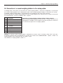
1.3
Safety and environment
Do not use the terminal in a hazardous area (except those versions specially marked
for this).
IP 65
Although the IND4.. terminals have IP65 protection, they may not be used in areas
where there is risk of corrosion. The terminal must never be flooded or submerged
in liquid!
Before connecting to the power supply, ensure that the local line voltage is the same
as the voltage stated on the rear of the scale. If these differ, the terminal must not be
connected (please contact your local Sales Office).
If the power cable is damaged, then the weighing system should not be operated. The
cable must therefore be regularly checked.
Using the Spider terminal in food processing: Those parts in contact with foodstuffs
have smooth surfaces and are easy to clean. The materials used in their construction
do not crack and contain no harmful substances. A protective (optional) cover is recommended when using the terminal in food processing. This must be cleaned
regularly. Damaged or dirty protective covers should be replaced immediately.
Please note all current environmental directives when disposing of the terminal.
Battery-powered terminals: The battery contains heavy metals and therefore must not
be disposed of as normal waste! Please observe local regulations when disposing of
environmentally harmful materials.
Chapter 2: Attaching weighing platforms
5
2
Attaching weighing platforms
All analog weighing platforms can be attached to IND4.. terminals if they are conform to the required specifications (see chapter 5).
Two different weighing platforms can be attached if the terminal also has an OptionPac with an analog option. Compact two-scale
systems can therefore be constructed using just one terminal.
2.1
Instructions on weighing cells
2.1.1
Cells with or without SENSE lines
In the case of cells without SENSE lines, the connections “+Ex” (Excitation) and “+Se” (Sense) or “–Ex” and “–Se” must be shortcircuited at the connection or the terminal in the OptionPac.
Cells without SENSE lines
Cells with SENSE lines
(required for certifiable weighing systems)
+Ex
+Se
+Ex
+Se
+Si
+Si
–Si
–Si
–Se
–Ex
–Se
–Ex
2.1.2
Attaching weighing platforms with several weighing cells
Up to 4 weighing cells can be connected in parallel to a terminal. These weighing cells can be connected in the usual way using
a junction box.
The sum of the rated capacities of the individual cells corresponds to the total capacity of the weighing system. When entering the
weighing capacities in the menu-driven dialog (chapter 4), the values should be selected so that the individual cells are not
overloaded!
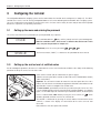
2.2
Preparing the connecting cable for the weighing platform
Remove the insulation as shown on the left.
135 mm
15 mm
5 mm
Note: For connecting to the analog option, only 100 mm of
cable insulation should be removed.
Chapter 2: Attaching weighing platforms
6
2.3
Attaching the weighing platform to the terminal
Before assembling, the terminal must first be disconnected
from the power supply!
Undo the gland nut of the heavy gauge cable gland and remove
this together with the black crimping ferrule and the two washers.
Undo the rear cover plate of the terminal (6 Torx T20 screws)
and fold down carefully (cable connections!).
Mount the nut, crimping ferrule and the washer with the larger
hole on the connecting cable of the weighing platform. Flange the
shield of the cable slightly and place the second washer over it.
Insert the cable through the heavy gauge cable gland of the
terminal.
Remove the green plug from the terminal. The plug connector is
fitted with a latch to simplify plugging in and out. The diagram
opposite shows the position of the connector in the terminal.
7-pin connector
+Ex +Se +Si
-Si -Se -Ex
Secure the individual strands of the connecting cable on the
connector. The pin assignment is shown in the diagram
opposite.
The connectors are marked as follows:
Si = Signal, Ex = Excitation, Se = Sense.
The 7-pin connector also has a terminal for signal ground in the
center. The signal ground can be led either to this signal ground
terminal or else connected to the shield of the cable (see
description and diagram above).
Attach the connector to the terminal. Caution: When inserting
the connector, ensure that it is centered exactly in the connector socket. If the connector is skew, then not all pins are
in contact!
Reassemble the rear cover plate of the terminal. Note that the
connecting cable of the weighing platform is not crimped!
Tighten the nut of the heavy gauge cable gland. Ensure that the
shield of the cable is held firmly between the two washers.
Chapter 2: Attaching weighing platforms
7
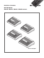
2.4 Connection of a second weighing platform to the analog option
The analog option, which allows the connection of a second weighing platform, is housed in the OptionPac. The connection
of a second weighing platform to the analog option requires that a weighing platform already be connected to the terminal.
The analog second weighing platform is connected directly to the OptionPac via a 9-pin Sub-D connector.
METTLER TOLED0 offers analog weighing platforms that are already equipped with a connector that is suitable for connection
to the analog option, so that no installation work is required.
Pin
Assignment
1
+ Excitation (+8,2 VDC)
2
+ Sense
3
Shield
4
– Sense
5
– Excitation
6
not assigned
7
+ Signal
8
– Signal
9
not assigned
Connection of analog weighing platforms without suitable connector
Connect analog weighing platforms that do not have a suitable connector to the
analog option in accordance with the adjacent connection assignment. Also observe
the connection assignment of the weighing platform.
Important: The analog second weighing platform is configured as a reference scale in the factory setting. “Bulk” (bulk scale)
or “Auxiliary” (auxiliary scale) can furthermore be selected in the interface menu “COMMUNICATION –> Option –> Mode”. The
weighing platform can be deactivated with the "Bypass" setting.
Then calibrate the weighing platform ("SCALE 2").
Chapter 3: Configuring the terminal
8
3
Configuring the terminal
The configuration data of the weighing system must be known before the terminal can be configured (see chapter 5). The IND4..
terminal has a service level for entering configuration data as well as for calibrating and linearization of the weighing system.
This level is protected by a password. The menus of the service level are used in exactly the same way as those for the operator
and for the supervisor (see operating instructions).
3.1
Calling up the menu and entering the password
The service level of the menu is protected by a special password (key sequence).
COdE
Press and hold down the
key until the prompt to enter the password appears.
Note: For certifiable scales, direct access is denied to the service level. In this
case, carry out the procedure in chapter 3.2.
Immediately enter the service password
SCALE
3.2
.
The first menu block (“SCALE”) is shown once the password has been entered.
Calling up the service level of certified scales
Due to metrological regulations, direct access is blocked to the service level of certified or certifiable scales. Carry out the following
procedure to call up the service level of such a scale:
Switch off the terminal (do not isolate from the power supply!).
Undo the rear cover plate of the terminal (6 Torx T20 screws) and fold down carefully
(cable connections!).
Important: The seal must be broken to remove the rear cover plate. Once the seal is
broken, the scale must be recertified by an approved certification center and a new seal
applied before it can be used again as a certified scale!
The service switch (push button) must first be pressed to call up the service level. This
is recessed and located next to the connector for the weighing platform (see opposite
figure). Use a suitable object or instrument to press down the switch (the blunt tip of a
pencil is recommended). Note: Before pressing the service switch, the
of battery-operated terminals must first be switched on.
switch
The terminal is switched on by pressing the switch, and the first block of the menu
(“SCALE”) is shown in the display. All menu blocks of the service level are now
accessible.
Reassemble the rear cover plate of the terminal.
Chapter 3: Configuring the terminal
9
3.3
Summary of menu blocks of the service level
The complete menu is available including those menu blocks to which operators and supervisors have access. The following
summary shows only those menu blocks of the service level in the menu “SCALE”. The rest of the menu is described in the operating
instructions.
Display
Remarks
Service level in menu block “SCALE”:
SCALE
Determining the admissibility for certification
––> chapter 3.4
Selecting the scale to be configured
(for two-scale system only, i.e. blocks only appear
if an analog option is available)
––> chapter 3.5
▼
Display of deflection of A/D converter (“ramp”)
––> chapter 3.6
▼
Calling up/changing the serial number
––> chapter 3.7
▼
Entering the configuration data
––> chapter 3.8
▼
Setting the Geo value
––> chapter 3.9
▼
Linearization with calibration
––> chapter 3.10
▼
Basic calibration
––> chapter 3.11
▼
MEtROLO
Activating the control mode
––> chapter 3.12
▼
▼
▼
Settings for the zero point
––> chapter 3.13
▼
SCALE 1
▼
▼
SCALE 2
▼
RAMP
▼
SNR
▼
SCAL.bLd
▼
GEO
▼
LIN - CAL
▼
CAL
○
▼
○
○
CONtROL
○
○
▼
○
○
ZERO
○
○
○
○
○
○
○
○
○
○
▼
○
▼
Navigating the menu:
▼
▼
In the following section, the arrows indicate how to operate the menu:
Pressing the
Pressing the
key (“YES”)
T
key (“NO”)
Pressing the
key jumps to the end of the menu (“End”)
Pressing the
key jumps backwards through the menu
Chapter 3: Configuring the terminal
10
Admissibility for certification (SCALE –> Metrology )
3.4
Display
Remarks
Setting the admissibility for certification:
▼
MEtROLO
NO APPr
▼
▼
▼
OIML
▼
Scale not certifiable.
Scale certifiable to OIML.
Caution: When a scale is declared certifiable, then certain settings are no longer
available. Direct access to the menu for the service technician is also blocked (see
chapter 3.2)!
Selecting the scale to be configured (SCALE –> Scale 1)
3.5
Display
Remarks
▼
This option is only available for two-scale systems, i.e. the terminal is fitted with an
analog option for connecting to a second weighing platform and the analog interface
is activated (see chapter 2.4)!
SCALE 1
▼
SCALE 2
Scale 1 should be configured.
Scale 2 (connected to the analog option) should be configured.
▼
Identical menu blocks are available in the service level for both scales. These are
described in the following chapters.
▼
Calling up the value of the A/D converter (SCALE –> Ramp)
3.6
Remarks
RAMP
▼
Display
▼ ▼
RMP 20
Displaying the analog/digital converter deflection (“ramp”) as a percentage.
This value determines whether the weighing cell is operating correctly. Scales with
identical and correctly functioning weighing cells have roughly the same ramp value.
This value is dynamic and changes as the load itself changes.
▼
Serial number of the terminal (SCALE –> SNR )
3.7
Remarks
SNR
▼
Display
1234567
Displaying or changing the serial number of the terminal. Note: The number should
be changed or re-entered only when necessary (e.g. after installing a new terminal
board).
For IND445 / 465 terminals, the serial number can be entered via the numeric
▼
keyboard. For IND425 / 435 terminals, press the
can now be changed using the
T
and
T
key. The first digit flashes and
keys. Confirm the new digit with the
key. The second digit now flashes and can be changed in the same way. This
▼
same procedure is used for all digits (total of 7 digits).
Chapter 3: Configuring the terminal
11
Entering the configuration data (SCALE –> Scale Build)
3.8
Display
Remarks
Entering configuration data
RESOL.
▼
SCL.CAP
––> chapter 3.8.1
▼
bAS.UNIt
Defining the type of scale
Specifying the basic units
––> chapter 3.8.2
▼
SCAL.tYP
Specifying the capacity of the weighing system
––> chapter 3.8.3
▼
▼
SCAL.bLd
Selecting the resolution
––> chapter 3.8.4
▼
▼
Defining the type of scale (SCALE –> Scale Build –> Scale Type )
3.8.1
Display
Remarks
Defining the scale type
▼
SCAL.tYP
SINGLE.R
“Single Range”: for the single range scale.
▼
2MULt.IN
▼
▼
2MULt.RN
▼
3MULt.IN
“Multi Intervall”: scale with one coarse range and 1 movable fine range. Automatic
switching between ranges in both directions.
“MultiRange”: scale with one coarse range and 1 fixed fine range. Automatic switching
to the coarse range. Returning to the fine range on reaching zero.
“Multi Intervall” scale with a coarse range and 2 movable fine ranges.
▼
3MULt.RN
▼
▼
“MultiRange” scale with one coarse range and 2 fixed fine ranges.
Setting the basic unit (SCALE –> Scale Build –> Basic Unit)
3.8.2
Display
Remarks
Setting the basic unit for entries in the service level.
bAS.UNIt
g
Gram
▼
kg
Kilogram
oz
Ounce
lb
Pound
▼
▼
▼
▼
Metric ton
▼
▼
t
Chapter 3: Configuring the terminal
12
Setting the scale capacity (SCALE –> Scale Build –> Scale Capacity)
3.8.3
Display
Remarks
Entering the scale capacity (in the preset basic unit).
▼
SCL.CAP
For IND445 / 465 terminals, the capacity can be entered via the numeric keyboard.
000015.0kg
For IND425 / 435 terminals, press the
▼
be changed using the
T
and
T
key. The first digit flashes and can now
keys. Confirm the new digit with the
key.
The second digit now flashes and can be changed in the same way. This same
procedure is used for all digits (total of 7 digits).
For a multirange scale (see chapter 3.8.1), this block is separately available for
each weighing range (“SCL.CAP 1” to “SCL.CAP 3”, depending on the number of
ranges). The additional blocks for capacity are each shown after the block for
“Resolution”. The upper limit is entered for each weighing range. Example when
using a 30 kg dual-range scale: “SCL.CAP 1” = 15 kg, “SCL.CAP 2” = 30 kg. In this
example, the ranges switch over from fine to coarse at 15 kg.
▼
Selecting the resolution (SCALE –> Scale Build –> Resolution )
3.8.4
Display
Remarks
Selecting the resolution (in the preset basic unit).
RESOL.
=0.001kg
▼
=0.002kg
▼
▼
=0.005kg
▼
The resolutions available depend on the capacity of the scale system. The diagram
opposite provides an example.
For a multirange scale (see chapter 3.8.1), this block is separately available for each
weighing range (“RESOL. 1” to “RESOL. 3”, depending on the number of ranges).
The additional blocks for resolution are each shown after the appropriate block for
entering the capacity (“SCL.CAP 1” to “SCL.CAP 3”).
▼
=0.01kg
▼
Setting the Geo value (SCALE –> Geo)
3.9
Display
Remarks
Setting the Geo value.
▼
GEO
With the Geo value, the scale system can be adjusted to local gravitational
0
▼
conditions. This value can be altered by pressing the T
▼
0 – 31). The table for Geo values is given in chapter 4.
▼
▼
31
and
keys (range
Chapter 3: Configuring the terminal
13
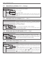
3.10 Linearization with calibration (SCALE –> Lin-Cal )
Display
Remarks
Linearizing the scale system with simultaneous calibration.
Calibration is carried out purely theoretically to compensate for
shifts in the full load when linearizing. The loads applied are
checked (±5%) and thus a basic calibration must first be
carried out (chapter 3.11).
▼
LIN - CAL
Apply preload, if applicable, then select the type of lineariza-
▼
3 POINt
– 3-point linearization (standard for 0%, 50% and 100% of
the full load).
– 5-point linearization (standard for 0%, 25%, 50%, 75%
and 100% of the full load).
- 0 -
After confirming the type of linearization, the display flashes
while the scale automatically determines the zero point. This zero
▼
5 POINt
key:
▼
tion/calibration and confirm with the
○
○
○
○
▼
○
○
○
○
○
○
○
○
○
point determination can be skipped by pressing the T key
in which case the existing zero point is used as the reference
point. This is especially useful for a large scale if test weights
have already been applied and which must be removed in order
to determine the zero point.
▼
○
▼
15.000kg
12.000kg
▼
▼
Change weight, if desired (values available depend on the capacity of the weighing system).
By applying the weight and confirming with the
first point is thus linearized. The scale then prompts for other
weights (the number of weights depends on the type of linearization selected), which may be changed as required. At the last
linearization point, the scale is also calibrated. The lineariza-
○
○
○
○
○
○
○
○
○
▼
○
▼
4.000kg
The scale prompts for a weight (half load for 3-point linearization or quarter load for 5-point linearization).
▼
○
○
○
○
○
○
○
○
○
○
donE
○
▼
○
key, the
tion/calibration can be exited at any time by pressing the
key.
The scale indicates that the linearization/calibration procedure
is completed once all points have been linearized.
Chapter 3: Configuring the terminal
14
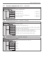
3.11 Basic calibration (SCALE –> Cal )
Display
Remarks
The basic calibration corresponds to the calibration function
for the user (however, the user cannot set the preload).
▼
CAL
Apply the preload and confirm with the
PRELOAd
key. If a test
weight is already on the scale, the preload measurement can
be skipped by pressing the T key. The existing zero point
is then used as the reference point. This is especially useful
for a large scale if test weights have already been applied and
which must be removed in order to determine the preload.
▼
▼
▼
6.000kg
5.000kg
▼
▼
2.000kg
▼
▼
○
○
▼
○
○
○
Change calibration weight, if desired (values available depend
on the capacity of the weighing system).
Apply the selected weight and confirm with the
key. (The
calibration can be exited at any time by pressing the
key).
▼
○
The scale prompts for a calibration weight corresponding to the
nominal capacity of the weighing system.
donE
Calibration is completed.
3.12 Activating the control mode (SCALE –> Control )
Display
Remarks
Activating the control mode.
▼
CONtROL
▼ ▼
The control mode displays the current weighing result at high resolution (but without
weighing unit). This enables the scale, for example, to be checked after calibration
and/or linearization.
7.246
▼
3.13 Settings for the zero point (SCALE –> Zero)
Display
Remarks
▼
AZM
––> chapter 3.13.1
▼
SEt.ZERO
Setting the zero capturing range
Moving the calibration zero point
––> chapter 3.13.2
▼
Z - CAPt
▼
▼
Settings for the zero point
▼
ZERO
This menu block also includes the block for automatic zero point correction. It is also
available to the user and is thus not described here (see operating instructions).
Chapter 3: Configuring the terminal
15
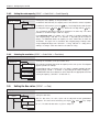
3.13.1 Setting the zero capturing range (SCALE –> Zero –> Zero Capture )
Display
Remarks
Setting the zero capturing range (when switching on and via the
▼
Z - CAPt
- 2 18
▼
▼
Zero capturing range –2% to +18%
Zero capturing range –2% to +2% (mainly for certifiable scales)
2
▼
-2
key).
▼
The zero capturing range is set at the expense of the nominal capacity of the scale.
If the capacity of the scale should be fully used, then the zero capturing range can be
reduced to –2% to +2%.
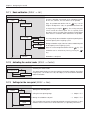
3.13.2 Moving the calibration zero point (SCALE –> Zero –> Set Zero)
Remarks
SEt.ZERO
▼
Display
▼
SURE?
Moving the calibration zero point is required: when an auxiliary preload is used or
the scale cannot be calibrated with the current preload (e.g. roller track) because
the values are outside the zero capturing range (in this case, the scale cannot be
started). The appropriate preload must be applied to the scale in order to carry out
a “Set Zero”. The zero point for calibration by the user is moved to the new value,
as is the zero capturing range.
Carry out or cancel moving of the calibration zero point.
▼
If, after exiting the menu, the display indicates underload or overload, the terminal
should be switched off and on again.
▼
3.14 Saving the settings and exiting the menu (End )
Remarks
End
▼
Display
▼
SAVE
This menu block is entered directly from any point in the menu by pressing the
key!
Save modified settings by pressing the
▼
T
key.
▼
0.00kg
The scale returns to weighing mode.
key or discard them by pressing the
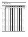
Chapter 4: Table of Geo values
16
4
Table of Geo values
Height above sea level in meters
Northern or southern
0
325
650
975
1300
1625
1950
2275
2600
2925
3250
325
650
975
1300
1625
1950
2275
2600
2925
3250
3575
geographical latitude
in degrees and minutes
0° 0'
5° 46'
9° 52'
12°44'
15° 6'
17°10'
19° 2'
20°45'
22°22'
23°54'
25°21'
26°45'
28° 6'
29°25'
30°41'
31°56'
33° 9'
34°21'
35°31'
36°41'
37°50'
38°58'
40° 5'
41°12'
42°19'
43°26'
44°32'
45°38'
46°45'
47°51'
48°58'
50° 6'
51°13'
52°22'
53°31'
54°41'
55°52'
57° 4'
58°17'
59°32'
60°49'
62° 9'
63°30'
64°55'
66°24'
67°57'
69°35'
71°21'
73°16'
75°24'
77°52'
80°56'
85°45'
-
5°
9°
12°
15°
17°
19°
20°
22°
23°
25°
26°
28°
29°
30°
31°
33°
34°
35°
36°
37°
38°
40°
41°
42°
43°
44°
45°
46°
47°
48°
50°
51°
52°
53°
54°
55°
57°
58°
59°
60°
62°
63°
64°
66°
67°
69°
71°
73°
75°
77°
80°
85°
90°
46'
52'
44'
6'
10'
2'
45'
22'
54'
21'
45'
6'
25'
41'
56'
9'
21'
31'
41'
50'
58'
5'
12'
19'
26'
32'
38'
45'
51'
58'
6'
13'
22'
31'
41'
52'
4'
17'
32'
49'
9'
30'
55'
24'
57'
35'
21'
16'
24'
52'
56'
45'
00'
Height above sea level in feet
0
1060
2130
3200
4260
5330
6400
7460
8530
9600
10660
1060
2130
3200
4260
5330
6400
7460
8530
9600
10660
11730
5
5
6
6
7
7
8
8
9
9
10
10
11
11
12
12
13
13
14
14
15
15
16
16
17
17
18
18
19
19
20
20
21
21
22
22
23
23
24
24
25
25
26
26
27
27
28
28
29
29
30
30
31
4
5
5
6
6
7
7
8
8
9
9
10
10
11
11
12
12
13
13
14
14
15
15
16
16
17
17
18
18
19
19
20
20
21
21
22
22
23
23
24
24
25
25
26
26
27
27
28
28
29
29
30
30
4
4
5
5
6
6
7
7
8
8
9
9
10
10
11
11
12
12
13
13
14
14
15
15
16
16
17
17
18
18
19
19
20
20
21
21
22
22
23
23
24
24
25
25
26
26
27
27
28
28
29
29
30
3
4
4
5
5
6
6
7
7
8
8
9
9
10
10
11
11
12
12
13
13
14
14
15
15
16
16
17
17
18
18
19
19
20
20
21
21
22
22
23
23
24
24
25
25
26
26
27
27
28
28
29
29
3
3
4
4
5
5
6
6
7
7
8
8
9
9
10
10
11
11
12
12
13
13
14
14
15
15
16
16
17
17
18
18
19
19
20
20
21
21
22
22
23
23
24
24
25
25
26
26
27
27
28
28
29
2
3
3
4
4
5
5
6
6
7
7
8
8
9
9
10
10
11
11
12
12
13
13
14
14
15
15
16
16
17
17
18
18
19
19
20
20
21
21
22
22
23
23
24
24
25
25
26
26
27
27
28
28
2
2
3
3
4
4
5
5
6
6
7
7
8
8
9
9
10
10
11
11
12
12
13
13
14
14
15
15
16
16
17
17
18
18
19
19
20
20
21
21
22
22
23
23
24
24
25
25
26
26
27
27
28
1
2
2
3
3
4
4
5
5
6
6
7
7
8
8
9
9
10
10
11
11
12
12
13
13
14
14
15
15
16
16
17
17
18
18
19
19
20
20
21
21
22
22
23
23
24
24
25
25
26
26
27
27
1
1
2
2
3
3
4
4
5
5
6
6
7
7
8
8
9
9
10
10
11
11
12
12
13
13
14
14
15
15
16
16
17
17
18
18
19
19
20
20
21
21
22
22
23
23
24
24
25
25
26
26
27
0
1
1
2
2
3
3
4
4
5
5
6
6
7
7
8
8
9
9
10
10
11
11
12
12
13
13
14
14
15
15
16
16
17
17
18
18
19
19
20
20
21
21
22
22
23
23
24
24
25
25
26
26
0
0
1
1
2
2
3
3
4
4
5
5
6
6
7
7
8
8
9
9
10
10
11
11
12
12
13
13
14
14
15
15
16
16
17
17
18
18
19
19
20
20
21
21
22
22
23
23
24
24
25
25
26
Chapter 5: Setting up a weighing system and technical data
17
5
Setting up a weighing system and technical data
Before setting up a weighing system with the IND4.. terminal, its basic data must first be determined. These data are to be entered
into the service level of the menu (chapter 3). The typical procedure for setting up a scale system is shown below as follows.
5.1
Selecting the weighing cell(s)
The following data must be known in order to determine the capacity of the weighing cell:
– Scale capacity: This generally corresponds to the heaviest load that is to be weighed with the weighing system.
– Preload: This is the total weight of all parts applied to the weighing cell. This includes the upper part of the weighing platform,
the weighing pan and all other components such as a roller track, a fixed weighing container, etc.
– Total zero setting range: This consists of the switch-on zero setting range (+18/–2% or ±2%, selected in the menu) and the
zero setting range (2%) that the user has available with the
key. The total zero setting range is thus either 20% or 4%
of the weighing capacity.
The sum of the weighing capacity, preload and total zero setting range thus gives the total capacity of the weighing cell required.
An additional safety margin should also be included in order to prevent weighing cells from being overloaded.
Total capacity of weighing cell(s) = scale capacity + preload + total zero setting range + safety margin
For systems with several weighing cells, the total theoretical capacity is divided by the number of cells (max. 4) in order to determine
the capacity of the individual cell. A sufficient safety margin is especially important if the scale is heavily loaded in the cornerload
range so that the load is no longer evenly distributed over all cells.
For systems with lever mechanisms, the total theoretical capacity is divided by the transmission ratio of the lever system in order
to determine the capacity of the cell.
When selecting the weighing cell(s), other parameters are also to be taken into account. These include:
– the smallest display step desired
– requirements for admissibility for certification
– number and type of weighing ranges
The terminal supplies a voltage of 8.2 V to the weighing cell(s). The maximum weighing signal is determined by multiplying the
power supply voltage by the sensitivity of the weighing cell:
Sensitivity of the cell
Power supply voltage
Max. weighing signal
1)
Min. weighing signal per display step (for certifiable scales)
1)
2 mv/V
3 mv/V
8.2 V
8.2 V
16.4 mV
24.6 mV 1)
0.5 µV/e
0.5 µV/e
Only 20 mV measurable by the A/D converter, so that scale capacity is only max. 81% of the cell capacity.
Chapter 5: Setting up a weighing system and technical data
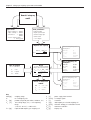
18
How do I set up my
scale?
Application:
Scale parameters:
– simple weighing – > IND425
– heaviest weight?
– simple counting – > IND435
– weight of pan holder?
– convenient ct.
– smallest display step?
– > IND445
IND465
– 2-scale counting system
–> Analog option
– certified scale?
– 1 or 2 ranges?
Required cell capacity
Data of weighing cell
Example A:
Max + E0 +
E min=
Max * EN
100
N
OIML R60:
Emax (=E):
nLC (=n):
Vmin:
CN (=S):
C3
10 kg
3000
Emax/7500
2 mV/V
Data of weighing cell
Example B:
Data of terminal
Check
(acc. to certification)
(in case of several weighing
ranges check the finest one)
U e:
8.2 V
Umin:
0.5 µV/e
nmax :
7500e
Umin
e
=
>=
Ue * S * Max * 1000
n*E*N
OIML R60:
R.C. (=E):
(–> n:
(–> Vmin:
R.O. (=S):
C3/30%
10 kg
3000)
E * 30% / n
2 mV/V
0.5 µV
e
Data of weighing cell
Example C:
Entries in menu block
“SCALE”
Max
–>
SCL. CAP
EN
–>
2-CAPt
Vmin
–>
RESOL.
OIML R60:
Emax (=E):
nLC (=n):
Vmin:
Cn (=S):
C3
550 kg
3000
0.01% * Cn
1.94 mV/V
Key:
Max [kg]:
N:
E0 [kg]:
EN [%]:
Emin [kg]:
weighing range
no. of weighing cells
preload (weight of pan holder, container, etc.)
zero setting range (2%) + zero capturing
range
(+18/–2% or ±2%) = 20% or 4%
required load capacity per weighing cell
Ue [V]:
S [mV/V]:
n [e]:
E [kg]:
Umin [µV/e]:
n max [e]:
Vmin [g]:
power supply from terminal
cell output signal
resolution
load capacity of selected weighing cell
minimum voltage per verification interval
maximum resolution
display step
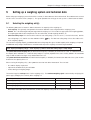
Chapter 5: Setting up a weighing system and technical data
19
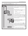
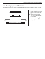
5.2
Measuring ranges of the IND4.. terminal
When setting up a weighing system, consider the measuring ranges of the IND4.. terminal according to the summary given below.
a: Total preload applied to weighing
cell when calibrating (upper part of
platform, weighing pan, roller track,
etc.)
Total capacity of weighing cell(s)
0%
a
100 %
b
c
Scale capacity
b: Switch-on zero capturing range:
+18/–2% or ±2% of weighing capacity (menu option)
d
c: Zero setting range with
±2% of weighing capacity (fixed)
Deflection of the A/D converter (“ramp”)
0%
100 %
Weighing cell signal, range of A/D converter
– 4 mV
0 mV
16.4 mV
key:
20 mV
d: Safety margin
Chapter 5: Setting up a weighing system and technical data
20
5.3
Technical data
Only those specifications needed for using this installation information are shown below. The other technical data are given in
the operating instructions.
Data for the terminal
Resolution
300 000 points for non-certifiable applications
7 500 points for certifiable applications
Weighing ranges
Up to 3 weighing ranges defined in the menu, incl. movable or fixed fine ranges.
For certifiable/certified applications, the minimum voltage per verification scale interval
(0.5 µV/e) must be maintained or the resolution must not exceed 7 500e.
Calibration
Basic calibration and calibration during linearization
Linearization
3-point or 5-point with simultaneous calibration
Zero setting range (
key)
2% of max. defined useful load, cannot be altered
Autozero range
2% of max. defined useful load, cannot be altered
Switch-on zero setting range
–2% ... 18% or –2% ... 2% of max. defined useful load (menu option)
Linearity
0.01% of the max. defined useful load
Units
g, kg, lb, oz, t
Display steps
1, 2, 5 x 10n (menu option)
Cell power supply
8.2 V
Scope of delivery
Terminal with power cable and local connector
Installation information for Spider terminal and operating instructions for Spider scale
Options: OptionPac with integrated analog option and other options
Requirements for the weighing cell
Nominal load
0.1 ... 999 999.9 (g, kg, lb, oz, t)
Admissible impedance
80 Ohm ... 1000 Ohm
Measure between Si+ and Si– or Ex+ and Ex– while weighing cell is disconnected
Differential signal
–1 mV ... 25 mV (see example below)
Example for calculating the differential signal:
Data of the weighing cell: sensitivity of 2 mV/V and cell capacity of 100 kg
Calculating the differential signal for nom. load (60 kg):
2 mV/V • 8.2 V • 60 kg/100 kg
=
9.84 mV
Calculating the differential signal for half load (30 kg):
2 mV/V • 8.2 V • 30 kg/100 kg
=
4.92 mV
Requirements for certifiable scales
– Certifiable weighing cell with SENSE lines (6 wires), sensitivity of the cell of 2 mV/V or 3 mV/V.
– The scale must be configured in the service level of the menu as certifiable (see chapter 3).
– Approved markings from the manufacturer (if the complete scale is not supplied by METTLER TOLEDO).
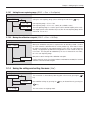
Chapter 6: Event and error messages
21
6
Event and error messages
Overload: Reduce the load on the scale or reduce the preload.
Underload: Place the weighing pan on the scale and ensure it can move freely.
Result not stable: Always appears when not stable (when zeroing, taring, etc.). If the scale still does not
become stable after a long time, check the environmental conditions. If necessary, change the setting of the
vibration adapter or use the dynamic weighing function.
Function not allowed: The requested function cannot be executed because it is not allowed at the time of the
request.
Zeroing not possible: Make sure that zeroing is being performed in the allowed range and not with overload
or underload. Note: The message
also appears if it is attempted to tare certified scales with
minus values (this is not allowed).
Reference weight too low: The weight on the pan is too low to use as a valid reference for piece counting.
Place a larger number of reference pieces on the weighing pan.
No valid value from reference scale: Only occurs when piece counting on a 2-scale system. Check cable
connecting the scales and check interface settings.
Not calibrated/adjusted: Disconnect the power supply plug and reconnect it (or if the scale is battery-operated,
switch it off and then on again). If the message appears again, calibrate/adjust the scale.
Reference piece weight too low: When determining the reference, the resulting weight of a single piece is
below the allowable limit. Piece counting is not possible for such pieces.
Unstable weight value when determining reference: When determining the reference for piece counting, the
weight value did not become stable and the scale cannot determine the reference piece weight. Check the
environmental conditions. If necessary, change the setting of the vibration adapter.
Input error for target value or tolerances: The value entered is invalid, enter another value.
Setting the reference piece weight is not allowed: Do not define a reference piece weight while a weight
totaling is in process.
Switching over the weighing unit is not allowed (totaling): Do not switch over the weighing unit while a
weight totaling is in process.
Printout not yet complete: Repeat the desired action after the current printout is complete.
Changing the weighing unit not allowed (dynamic weighing): Do not change the weighing unit while you
are dynamic weighing.
EAROM checksum error: Disconnect the power supply plug and reconnect it (or if the scale is battery-operated,
switch the scale off and then on again). If the message re-appears, press the
key continuously. The
display shows “Flush” and then the scale is restarted. After start-up, the scale shows “Error 6” (missing
calibration data). All scale data must be re-entered and the scale recalibrated.
12234456781
22011473B
Subject to technical changes
© Mettler-Toledo (Albstadt) GmbH 05/08
Mettler-Toledo (Albstadt) GmbH
D-72458 Albstadt
Tel. ++49-7431-14 0, Fax ++49-7431-14 232
Internet: http://www.mt.com
Printed in Germany 22011473B