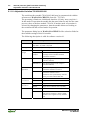
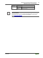
1
Fieldbus Independent I/O Modules SSI Transmitter Interface 750-630 Manual Version 1.1.1 ii • General Copyright 2008 by WAGO Kontakttechnik GmbH & Co. KG All rights reserved. WAGO Kontakttechnik GmbH & Co. KG Hansastraße 27 D-32423 Minden Phone: +49 (0) 571/8 87 – 0 Fax: +49 (0) 571/8 87 – 1 69 E-Mail: [email protected] Web: http://www.wago.com Technical Support Phone: +49 (0) 571/8 87 – 5 55 Fax: +49 (0) 571/8 87 – 85 55 E-Mail: [email protected] Every conceivable measure has been taken to ensure the correctness and completeness of this documentation. However, as errors can never be fully excluded, we would appreciate any information or ideas at any time. E-Mail: [email protected] We wish to point out that the software and hardware terms as well as the trademarks of companies used and/or mentioned in the present manual are generally trademark or patent protected. WAGO-I/O-SYSTEM 750 I/O Modules Content • iii Content 1 Important Notes .......................................................................................... 4 1.1 Legal Bases............................................................................................... 4 1.1.1 Copyright ............................................................................................. 4 1.1.2 Personnel Qualifications...................................................................... 4 1.1.3 Use of the 750 Series in Compliance with Underlying Provisions ..... 5 1.1.4 Technical Condition of Specified Devices .......................................... 5 1.2 Standards and Guidelines for Operating the 750 Series........................... 6 1.3 Symbols .................................................................................................... 7 1.4 Safety Information.................................................................................... 8 1.5 Font Conventions ..................................................................................... 9 1.6 Number Notation ...................................................................................... 9 1.7 Scope ...................................................................................................... 10 2 I/O Modules ............................................................................................... 11 2.1 Special Modules ..................................................................................... 11 2.1.1 750-630 (/xxx-xxx) [SSI Transmitter Interface] ............................... 11 2.1.1.1 Variations...................................................................................... 11 2.1.1.2 View.............................................................................................. 11 2.1.1.3 Description.................................................................................... 12 2.1.1.4 Display Elements .......................................................................... 13 2.1.1.5 Schematic Diagram....................................................................... 13 2.1.1.6 Technical Data .............................................................................. 14 2.1.1.7 Process Image ............................................................................... 16 2.1.1.8 Adjustable Variation 750-630/003-000 ........................................ 18 3 Use in Hazardous Environments ............................................................. 20 3.1 Marking Configuration Examples .......................................................... 21 3.1.1 Marking for Europe according to CENELEC and IEC ..................... 21 3.1.2 Marking for America according to NEC 500 .................................... 24 3.2 Installation Regulations.......................................................................... 25 3.2.1 Special Conditions for Safe Operation of the ATEX and IEC Ex (acc. DEMKO 08 ATEX 142851X and IECEx PTB 07.0064).................. 26 3.2.2 Special conditions for safe use (ATEX Certificate TÜV 07 ATEX 554086 X) .......................................................................................... 27 3.2.3 Special conditions for safe use (IEC-Ex Certificate TUN 09.0001 X)29 3.2.4 Special conditions for safe use (ATEX Certificate DEKRA 11ATEX0203 X) ............................................................................... 31 3.2.5 ANSI/ISA 12.12.01 ........................................................................... 32 WAGO-I/O-SYSTEM 750 I/O Modules 4 • Content Legal Bases 1 Important Notes This section includes an overall summary of the most important safety requirements and notes that are mentioned in each individual section. To protect your health and prevent damage to devices as well, it is imperative to read and carefully follow the safety guidelines. 1.1 Legal Bases 1.1.1 Copyright This Manual, including all figures and illustrations, is copyright-protected. Any further use of this Manual by third parties that violate pertinent copyright provisions is prohibited. Reproduction, translation, electronic and phototechnical filing/archiving (e.g., photocopying) as well as any amendments require the written consent of WAGO Kontakttechnik GmbH & Co. KG, Minden, Germany. Non-observance will involve the right to assert damage claims. WAGO Kontakttechnik GmbH & Co. KG reserves the right to provide for any alterations or modifications that serve to increase the efficiency of technical progress. WAGO Kontakttechnik GmbH & Co. KG owns all rights arising from the granting of patents or from the legal protection of utility patents. Third-party products are always mentioned without any reference to patent rights. Thus, the existence of such rights cannot be excluded. 1.1.2 Personnel Qualifications The use of the product described in this Manual requires special personnel qualifications, as shown in the following table: Activity Electrical specialist Assembly X Commissioning X Instructed personnel*) X X Programming *) Specialists**) having qualifications in PLC programming X Maintenance X Troubleshooting X Disassembly X X X Instructed persons have been trained by qualified personnel or electrical specialists. **) A specialist is a person, who – thanks to technical training – has the qualification, knowledge and expertise to meet the required specifications of this work and to identify any potential hazardous situation in the above listed fields of activity. WAGO-I/O-SYSTEM 750 I/O Modules Important Notes Legal Bases • 5 All responsible persons have to familiarize themselves with the underlying legal standards to be applied. WAGO Kontakttechnik GmbH & Co. KG does not assume any liability whatsoever resulting from improper handling and damage incurred to both WAGO´s own and third-party products by disregarding detailed information in this Manual. 1.1.3 Use of the 750 Series in Compliance with Underlying Provisions Couplers, controllers and I/O modules found in the modular WAGO-I/OSYSTEM 750 receive digital and analog signals from sensors and transmit them to the actuators or higher-level control systems. Using programmable controllers, the signals can also be (pre-)processed. The components have been developed for use in an environment that meets the IP20 protection class criteria. Protection against finger injury and solid impurities up to 12.5 mm diameter is assured; protection against water damage is not ensured. Unless otherwise specified, operation of the components in wet and dusty environments is prohibited. 1.1.4 Technical Condition of Specified Devices The components to be supplied Ex Works, are equipped with hardware and software configurations, which meet the individual application requirements. Changes in hardware, software and firmware are permitted exclusively within the framework of the various alternatives that are documented in the specific manuals. WAGO Kontakttechnik GmbH & Co. KG will be exempted from any liability in case of changes in hardware or software as well as to noncompliant usage of components. Please send your request for modified and new hardware or software configurations directly to WAGO Kontakttechnik GmbH & Co. KG. WAGO-I/O-SYSTEM 750 I/O Modules 6 • Content Standards and Guidelines for Operating the 750 Series 1.2 Standards and Guidelines for Operating the 750 Series Please adhere to the standards and guidelines required for the use of your system: The data and power lines shall be connected and installed in compliance with the standards required to avoid failures on your system and to substantially minimize any imminently hazardous situations resulting in personal injury. For assembly, start-up, maintenance and troubleshooting, adhere to the specific accident prevention provisions which apply to your system (e.g. BGV A 3, "Electrical Installations and Equipment"). Emergency stop functions and equipment shall not be made ineffective. See relevant standards (e.g. DIN EN 418). The equipment of your system shall be conform to EMC guidelines so that any electromagnetic interferences will be eliminated. Operating 750 Series components in home applications without further measures is permitted only if they meet the emission limits (emissions of interference) in compliance with EN 61000-6-3. You will find the detailed information in section "WAGO-I/O-SYSTEM 750" "System Description" "Technical Data". Please observe the safety precautions against electrostatic discharge in accordance with DIN EN 61340-5-1/-3. When handling the modules, please ensure that environmental factors (persons, working place and packaging) are well grounded. The valid standards and guidelines applicable for the installation of switch cabinets shall be adhered to. WAGO-I/O-SYSTEM 750 I/O Modules Important Notes Symbols • 7 1.3 Symbols Danger Always observe this information to protect persons from injury. Warning Always observe this information to prevent damage to the device. Attention Marginal conditions that must always be observed to ensure smooth and efficient operation. ESD (Electrostatic Discharge) Warning of damage to the components through electrostatic discharge. Observe the precautionary measure for handling components at risk of electrostatic discharge. Note Make important notes that are to be complied with so that a trouble-free and efficient device operation can be guaranteed. Additional Information References to additional literature, manuals, data sheets and internet pages. WAGO-I/O-SYSTEM 750 I/O Modules 8 • Content Safety Information 1.4 Safety Information When connecting the device to your installation and during operation, the following safety notes must be observed: Danger The WAGO-I/O-SYSTEM 750 and its components are an open system. It must only be assembled in housings, cabinets or in electrical operation rooms. Access is only permitted via a key or tool to authorized qualified personnel. Danger All power sources to the device must always be switched off before carrying out any installation, repair or maintenance work. Warning Replace defective or damaged device/module (e.g. in the event of deformed contacts), as the functionality of field bus station in question can no longer be ensured on a long-term basis. Warning The components are not resistant against materials having seeping and insulating properties. Belonging to this group of materials is: e.g. aerosols, silicones, triglycerides (found in some hand creams). If it cannot be ruled out that these materials appear in the component environment, then the components must be installed in an enclosure that is resistant against the above mentioned materials. Clean tools and materials are generally required to operate the device/module. Warning Soiled contacts must be cleaned using oil-free compressed air or with ethyl alcohol and leather cloths. Warning Do not use contact sprays, which could possibly impair the functioning of the contact area. Warning Avoid reverse polarity of data and power lines, as this may damage the devices. ESD (Electrostatic Discharge) The devices are equipped with electronic components that may be destroyed by electrostatic discharge when touched. WAGO-I/O-SYSTEM 750 I/O Modules Important Notes Font Conventions • 9 Warning For components with ETHERNET/RJ-45 connectors: Only for use in LAN, not for connection to telecommunication circuits. 1.5 Font Conventions italic Names of paths and data files are marked in italic-type. e.g.: C:\Programs\WAGO-IO-CHECK italic Menu items are marked in italic-type, bold letters. e.g.: Save \ A backslash between two names characterizes the selection of a menu point from a menu. e.g.: File \ New END Pushbuttons are marked as bold with small capitals e.g.: ENTER <> Keys are marked bold within angle brackets e.g.: <F5> Courier The print font for program codes is Courier. e.g.: END_VAR 1.6 Number Notation Number code Example Note Decimal 100 Normal notation Hexadecimal 0x64 C notation Binary '100' '0110.0100' In quotation marks, nibble separated with dots (.) WAGO-I/O-SYSTEM 750 I/O Modules 10 • Important Notes Scope 1.7 Scope This manual describes the Digital Input Module 750-630 SSI Transmitter Interface of the modular WAGO-I/O-SYSTEM 750. Handling, assembly and start-up are described in the manual of the Fieldbus Coupler. Therefore this documentation is valid only in the connection with the appropriate manual. WAGO-I/O-SYSTEM 750 I/O Modules 750-630 (/xxx-xxx) [SSI Transmitter Interface] Variations • 11 2 I/O Modules 2.1 Special Modules 2.1.1 750-630 (/xxx-xxx) [SSI Transmitter Interface] 2.1.1.1 Variations Item-No. Designation Description 750-630 SSI/ 24Bit/ 125kHz/ Gray SSI Transmitter Interface 750-630/000-001 SSI/ 24Bit/ 125kHz/ Bin SSI Transmitter Interface 750-630/000-002 SSI/ 24Bit/ 250kHz/ Bin SSI Transmitter Interface 750-630/000-004 SSI/ 24Bit/ 125kHz/ Gray/ Status SSI Transmitter Interface 750-630/000-005 SSI/ 15Bit/ 125kHz/ Gray/ Status SSI Transmitter Interface 750-630/000-006 SSI/ 24Bit/ 250kHz/ Gray SSI Transmitter Interface 750-630/000-007 SSI/ 24Bit/ 83kHz/ Gray/ Status SSI Transmitter Interface 750-630/000-008 SSI/ 25Bit/ 125kHz/ Gray SSI Transmitter Interface 750-630/000-009 SSI/ 13Bit/ 250kHz/ Bin SSI Transmitter Interface 750-630/000-011 SSI/ 25Bit/ 125kHz/ Bin SSI Transmitter Interface 750-630/000-012 SSI/ 13Bit/ 125kHz/ Gray SSI Transmitter Interface 750-630/000-013 SSI/ 29Bit/ 125kHz/ Bin SSI Transmitter Interface 750-630/003-000 Variable configuration SSI Transmitter Interface 2.1.1.2 View 13 14 Status A C B D D+ D- Data contacts -D +D + + 24V - - 0V CL+ CL- -CL +CL 750-630 Power jumper contacts Fig. 2.1.1-2: View WAGO-I/O-SYSTEM 750 I/O Modules g063000e 12 • 750-630 (/xxx-xxx) [SSI Transmitter Interface] Description 2.1.1.3 Description This module is an SSI interface for the direct connection to an SSI transmitter. The power supply for the transmitter is derived internally from the power jumper contacts. After the interface has given a clock pulse to the sensor, the interface reads the incoming data and transmits it directly in the form of a data word into the process image of the PLC or PC. It is possible to factory adjust different operating modes, transfer frequencies and data widths by means of the control register. The operational readiness of the module is indicated via a green function LED. Any configuration of the specialty modules is possible when designing the fieldbus node. Grouping of module types is not necessary. The field side supply voltage of 24 V for the output module is derived from adjacent I/O modules or from a supply module. The supply voltage for the field side is made automatically through the individual I/O modules by means of power jumper contacts. Attention The module has no power jumper contact for receiving and transmitting the ground (earth) potential. A supply module is required, if the adjacent modules need to be connected to the earth. Warning The maximum current of the internal power jumper contacts is 10 A. When configuring the system it is important not to exceed the maximum/sum current. However, if such a case should occur, another supply module must be added. The module 750-630 and its variations can be used with all couplers/controllers of the WAGO-I/O-SYSTEM 750 (except for the economy types 750-320, -323, -324 and -327). This description is valid from hardware and software version XXXX3A05... and up. The version is specified in the manufacturing number, which is part of the lateral marking on the module. WAGO-I/O-SYSTEM 750 I/O Modules 750-630 (/xxx-xxx) [SSI Transmitter Interface] Display Elements • 13 2.1.1.4 Display Elements LED Channel State Function Watchdog Timer Overflow * 13 14 A A C B A D * The green LED goes off if no process data is transmitted by the fieldbus coupler / controller for 100 ms. off Status Fig. 2.1.1-1: Display Elements green g063002x Normal operation 2.1.1.5 Schematic Diagram +5V 2k2 +D 270pF 120R 270pF +D 1 2 5 -D -D 2k2 0V 6 24V 270pF 24V +5V DC 100nF 270pF 3 0V_EX 7 0V DC Logic 0V Status +CL 270pF +CL 4 8 -CL 750-630 Fig. 2.1.1-2: Schematic Diagram WAGO-I/O-SYSTEM 750 I/O Modules 270pF -CL g063001e 14 • 750-630 (/xxx-xxx) [SSI Transmitter Interface] Technical Data 2.1.1.6 Technical Data Module Specific Data Transmitter connection Inputs: + D, -D, Outputs: +CL, -CL Current consumption typ. (internal) 85 mA Voltage via power jumper contacts DC 24 V (-15 % ... +20 %) Transmission rate 125 kHz (max. 1 MHz) Serial Input max. 32 bit width (adjustable) Signal output (+CL, -CL) differential signal (RS 422) Signal input (+D, -D) differential signal (RS 422) Code Gray / Bin Internal bit width 1 x 32 bits (24 bit used, 8 bit reserved) 2 x 8 bits control/status (option) Isolation 500 V (System/Supply) Dimensions W x H* x L * from upper edge of 35 DIN rail 12 mm x 64 mm x 100 mm Weight ca. 55 g Approvals (cf. Chapter 2.2 of the Coupler/Controller Manual) Conformity Marking CULUS (UL508) WAGO-I/O-SYSTEM 750 I/O Modules 750-630 (/xxx-xxx) [SSI Transmitter Interface] Technical Data • 15 The following Ex approvals have been granted to the basic version of 750-630 I/O modules and the variation 750-630/000-xxx: KEMA (01 KEMA 1024X) II 3 G EEx nA II T4 CULUS Class I Div2 ABCD T4 (ANSI/ISA 12.12.01) The following Ex approvals have been granted to the variation 750-630/003000: TÜV (07 ATEX 554086 X) I M2 Ex d I II 3 G Ex nA IIC T4 II 3 D Ex tD A22 IP6X T135°C Permissible operation temperature: 0 °C ≤ TA ≤ +60 °C TÜV (TUN 09.0001X) Ex d I Ex nA IIC T4 Ex tD A22 IP6X T135°C Permissible operation temperature: 0 °C ≤ TA ≤ +60 °C CULUS (ANSI/ISA 12.12.01) Class I Div2 ABCD T4 More Information Detailed references to the approvals are listed in the document "Overview Approvals WAGO-I/O-SYSTEM 750", which you can find on the CD ROM ELECTRONICC Tools and Docs (Item-No.: 0888-0412) or in the internet under: http://www.wago.com Documentation WAGO-I/O-SYSTEM 750 System Description WAGO-I/O-SYSTEM 750 I/O Modules 16 • 750-630 (/xxx-xxx) [SSI Transmitter Interface] Process Image 2.1.1.7 Process Image Using the I/O module 750-630, a 5 byte input and output process image can be transferred to the fieldbus coupler / controller via one logical channel. The data received by the transmitter are stored in 3 input bytes (D0 ... D2). Neither the input byte (D3) and four output bytes (D0 ... D3) nor the control byte (C0) are used. The status byte (S0) indicates transmitter or cable errors (only versions 750-630/000-004, /000-005 and /000-007). Processing the status byte via the coupler / controller is optional, which means that accessing or parsing the status information depends on the fieldbus system. Attention The representation of the process data of some I/O modules or their variations in the process image depends on the fieldbus coupler/-controller used. Please take this information as well as the particular design of the respective control/status bytes from the section "Fieldbus Specific Design of the Process Data" included in the description concerning the process image of the corresponding coupler/controller. Input data Output data S0 Status byte C0 Control byte D0 Process data byte 0 (LSB) D0 0 (reserved) D1 Process data byte 1 D1 0 (reserved) D2 Process data byte 2 (MSB) D2 0 (reserved) D3 0 (reserved) D3 0 (reserved) Control byte C0 0 Bit 7 Bit 6 Bit 5 Bit 4 Bit 3 Bit 2 Bit 1 Bit 0 0 0 0 0 0 0 0 0 reserved WAGO-I/O-SYSTEM 750 I/O Modules 750-630 (/xxx-xxx) [SSI Transmitter Interface] Process Image • 17 Status byte S0 Bit 7 Bit 6 Bit 5 Bit 4 Bit 3 Bit 2 0 ERROR 0 0 0 0 Bit 1 Bit 0 FRAME_ SSI_IN_ E E ERROR A general error has occurred. This bit is set in a FRAME or SSI-IN error has occurred. FRAME_E An invalid data frame has occurred, i.e. the data frame is not terminated with zero (possibly a wire breakage on clock lines). SSI_IN_E The SSI input of the module has low level when no data transfer is taking place. (SSI has swapped no power supply or wire breakage at the SSI data inputs D+ or D- or data lines). 0 reserved WAGO-I/O-SYSTEM 750 I/O Modules 18 • 750-630 (/xxx-xxx) [SSI Transmitter Interface] Adjustable Variation 750-630/003-000 2.1.1.8 Adjustable Variation 750-630/003-000 The serial interface module 750-630/003-000 may be parameterized with the software tool WAGO-I/O-CHECK 2 (Item-No.: 759-302). The presetting is Baud rate: 9600 baud, data bits: 8, Parity: none, stop bits: 1. In this mode of operation the module has the same behavior and also the same process values as the base module 750-630. If another mode of operation is selected by changing the parameters, then the module behaves according to the variation with the selected mode of operation. The parameter dialog box in WAGO I/O CHECK 2 offers selection fields for the available settings of this I/O module. The following description is valid for software version 41. Select box Available settings Baudrate 1,0 MHz / 250,0kHz / 125,0 kHz* / 100,0 kHz / 83,0 kHz / 71,0 kHz / 62,5 kHz PI-Length 0 Byte ... 24 Byte* ... 32 Byte (numeric input box) Var. Frame Length Not used* Variable data frame not active 1 Byte / ... / 32 Byte Variable data frame length for the data exchange between module and SSI Transmitter Interface Standard (see mapping-tables in the coupler- / controller-manual) Alternative* (see mapping-tables in the coupler- / controller-manual) Disable* Synchronous operating mode of the SSI Transmitter Interface not active Enable Synchronous operating mode of the SSI Transmitter Interface active The data is sent synchronously with the read cycle of the internal data bus. Disable Gray-Dualcode conversion not active Enable* Gray-Dualcode conversion active Disable* Single-Turn evaluation not active Enable Single-Turn evaluation active (13 Bit) Disable Frame error not active Enable* Frame error active After the last valid bit, a check is made whether a zero signal is sent by the data line. Output format Synchronous Operation Gray-Dualcode Conversion Single-Turn Evaluation Frame Error WAGO-I/O-SYSTEM 750 I/O Modules 750-630 (/xxx-xxx) [SSI Transmitter Interface] Adjustable Variation 750-630/003-000 Select box Available settings Power Fail Bit Disable* Power fail bit not active (PFB) Enable Power fail bit active • 19 * default setting More Information Detailed Information about the parameterizing this module can be found in the manual for the software tool WAGO-I/O-CHECK or in the Internet under: http://www.wago.com . WAGO-I/O-SYSTEM 750 I/O Modules 20 • Use in Hazardous Environments 3 Use in Hazardous Environments The WAGO-I/O-SYSTEM 750 (electrical equipment) is designed for use in Zone 2 hazardous areas. The following sections include both the general identification of components (devices) and the installation regulations to be observed. The individual subsections of the "Installation Regulations" section must be taken into account if the I/O module has the required approval or is subject to the range of application of the ATEX directive. WAGO-I/O-SYSTEM 750 I/O Modules Use in Hazardous Environments • 21 3.1 Marking Configuration Examples 3.1.1 Marking for Europe according to CENELEC and IEC Figure 1: Side marking example for ATEX and IEC Ex approved I/O modules according to CENELEC and IEC Figure 2: Printing Text detail – Marking example for ATEX and IEC Ex approved I/O modules according to CENELEC and IEC Table 1: Description of marking example for ATEX and IEC Ex approved I/O modules according to CENELEC and IEC Printing on Text DEMKO 08 ATEX 142851 X IECEx PTB 07.0064X I M2 / II 3 GD Ex nA IIC T4 WAGO-I/O-SYSTEM 750 I/O Modules Description Approval body and/or number of the examination certificate Explosion protection group and Unit category Type of ignition and extended identification Explosion protection group Temperature class 22 • Use in Hazardous Environments Figure 3: Side marking example for Ex i and IEC Ex i approved I/O modules according to CENELEC and IEC Figure 4: Text detail – Marking example for Ex i and IEC Ex i approved I/O modules according to CENELEC and IEC WAGO-I/O-SYSTEM 750 I/O Modules Use in Hazardous Environments • 23 Table 2: Description of marking example for Ex i and IEC Ex i approved I/O modules according to CENELEC and IEC Inscription text TÜV 07 ATEX 554086 X TUN 09.0001X Dust II 3(1)D Ex tD [iaD] A22 IP6X T 135°C Mining I (M2) [Ex ia] I Gases II 3(1)G Ex nA [ia] IIC T4 WAGO-I/O-SYSTEM 750 I/O Modules Description Approving authority or certificate numbers Device group: All except mining Device category: Zone 22 device (Zone 20 subunit) Explosion protection mark Protection by enclosure Approved in accordance with "Dust intrinsic safety" standard Surface temperature determined according to Procedure A, use in Zone 22 Dust-tight (totally protected against dust) Max. surface temp. of the enclosure (no dust bin) Device group: Mining Device category: High degree of safety Explosion protection: Mark with category of type of protection intrinsic safety: Even safe when two errors occur Device group: Mining Device group: All except mining Device category: Zone 2 device (Zone 0 subunit) Explosion protection mark Type of protection: Non-sparking operating equipment Category of type of protection intrinsic safety: Even safe when two errors occur Explosion Group Temperature class: Max. surface temperature 135°C 24 • Use in Hazardous Environments 3.1.2 Marking for America according to NEC 500 Figure 5: Side marking example for I/O modules according to NEC 500 Figure 6: Text detail – Marking example for I/O modules according to NEC 500 Table 3: Description of marking example for I/O modules according to NEC 500 Printing on Text CL 1 DIV 2 Grp. ABCD Optemp code T4 Description Explosion protection group (condition of use category) Area of application (zone) Explosion group (gas group) Temperature class WAGO-I/O-SYSTEM 750 I/O Modules Use in Hazardous Environments • 25 3.2 Installation Regulations In the Federal Republic of Germany, various national regulations for the installation in explosive areas must be taken into consideration. The basis for this forms the working reliability regulation, which is the national conversion of the European guideline 99/92/E6. They are complemented by the installation regulation EN 60079-14. The following are excerpts from additional VDE regulations: Table 4: VDE Installation Regulations in Germany DIN VDE 0100 Installation in power plants with rated voltages up to 1000 V DIN VDE 0101 Installation in power plants with rated voltages above 1 kV DIN VDE 0800 Installation and operation in telecommunication plants including information processing equipment DIN VDE 0185 lightning protection systems The USA and Canada have their own regulations. The following are excerpts from these regulations: Table 5: Installation Regulations in USA and Canada NFPA 70 National Electrical Code Art. 500 Hazardous Locations ANSI/ISA-RP 12.6-1987 Recommended Practice C22.1 Canadian Electrical Code Notice the following points When using the WAGO-I/O SYSTEM 750 (electrical operation) with Ex approval, the following points are mandatory: WAGO-I/O-SYSTEM 750 I/O Modules 26 • Use in Hazardous Environments 3.2.1 Special Conditions for Safe Operation of the ATEX and IEC Ex (acc. DEMKO 08 ATEX 142851X and IECEx PTB 07.0064) The fieldbus-independent I/O modules of the WAGO-I/O-SYSTEM 750-.../...-... must be installed in an environment with degree of pollution 2 or better. In the final application, the I/O modules must be mounted in an enclosure with IP 54 degree of protection at a minimum with the following exceptions: - I/O modules 750-440, 750-609 and 750-611 must be installed in an IP 64 minimum enclosure. I/O module 750-540 must be installed in an IP 64 minimum enclosure for 230 V AC applications. I/O module 750-440 may be used up to max. 120 V AC. When used in the presence of combustible dust, all devices and the enclosure shall be fully tested and assessed in compliance with the requirements of IEC 61241-0:2004 and IEC 61241-1:2004. When used in mining applications the equipment shall be installed in a suitable enclosure according to EN 60079-0:2006 and EN 60079-1:2007. I/O modules fieldbus plugs or fuses may only be installed, added, removed or replaced when the system and field supply is switched off or the area exhibits no explosive atmosphere. DIP switches, coding switches and potentiometers that are connected to the I/O module may only be operated if an explosive atmosphere can be ruled out. I/O module 750-642 may only be used in conjunction with antenna 758-910 with a max. cable length of 2.5 m. To exceed the rated voltage no more than 40%, the supply connections must have transient protection. The permissible ambient temperature range is 0 °C to +55 °C. WAGO-I/O-SYSTEM 750 I/O Modules Use in Hazardous Environments • 27 3.2.2 Special conditions for safe use (ATEX Certificate TÜV 07 ATEX 554086 X) 1. For use as Gc- or Dc-apparatus (in zone 2 or 22) the field bus independent I/O modules WAGO-I/O-SYSTEM 750-*** shall be erected in an enclosure that fulfils the requirements of the applicable standards (see the marking) EN 60079-0, EN 60079-11, EN 60079-15, EN 61241-0 and EN 61241-1. For use as group I, electrical apparatus M2, the apparatus shall be erected in an enclosure that ensures a sufficient protection according to EN 60079-0 and EN 60079-1 and the degree of protection IP64. The compliance of these requirements and the correct installation into an enclosure or a control cabinet of the devices shall be certified by an ExNB. 2. If the interface circuits are operated without the field bus coupler station type 750-3../…-… (DEMKO 08 ATEX 142851 X), measures must be taken outside of the device so that the rating voltage is not being exceeded of more than 40% because of transient disturbances. 3. DIP-switches, binary-switches and potentiometers, connected to the module may only be actuated when explosive atmosphere can be excluded. 4. The connecting and disconnecting of the non-intrinsically safe circuits is only permitted during installation, for maintenance or for repair purposes. The temporal coincidence of explosion hazardous atmosphere and installation, maintenance resp. repair purposes shall be excluded. 5. For the types 750-606, 750-625/000-001, 750-487/003-000, 750-484 the following shall be considered: The interface circuits shall be limited to overvoltage category I/II/III (non mains/mains circuits) as defined in IEC 60664-1. 6. For the type 750-601 the following shall be considered: Do not remove or replace the fuse when the apparatus is energized. 7. The ambient temperature range is: 0°C ≤ Ta ≤ +55°C (for extended details please note certificate). WAGO-I/O-SYSTEM 750 I/O Modules 28 • Use in Hazardous Environments 8. The following warnings shall be placed nearby the unit: Do not remove or replace fuse when energized! If the module is energized do not remove or replace the fuse. Do not separate when energized! Do not separate the module when energized! Separate only in a non-hazardous area! Separate the module only in a non-hazardous area! WAGO-I/O-SYSTEM 750 I/O Modules Use in Hazardous Environments • 29 3.2.3 Special conditions for safe use (IEC-Ex Certificate TUN 09.0001 X) 1. For use as Dc- or Gc-apparatus (in zone 2 or 22) the fieldbus independent I/O modules WAGO-I/O-SYSTEM 750-*** shall be erected in an enclosure that fulfils the requirements of the applicable standards (see the marking) IEC 60079-0, IEC 60079-11, IEC 60079-15, IEC 61241-0 and IEC 61241-1. For use as group I, electrical apparatus M2, the apparatus shall be erected in an enclosure that ensures a sufficient protection according to IEC 60079-0 and IEC 60079-1 and the degree of protection IP64. The compliance of these requirements and the correct installation into an enclosure or a control cabinet of the devices shall be certified by an ExCB. 2. Measures have to be taken outside of the device that the rating voltage is not being exceeded of more than 40% because of transient disturbances. 3. DIP-switches, binary-switches and potentiometers, connected to the module may only be actuated when explosive atmosphere can be excluded. 4. The connecting and disconnecting of the non-intrinsically safe circuits is only permitted during installation, for maintenance or for repair purposes. The temporal coincidence of explosion hazardous atmosphere and installation, maintenance resp. repair purposes shall be excluded. 5. For the types 750-606, 750-625/000-001, 750-487/003-000, 750-484 the following shall be considered: The interface circuits shall be limited to overvoltage category I/II/III (non mains/mains circuits) as defined in IEC 60664-1. 6. For the type 750-601 the following shall be considered: Do not remove or replace the fuse when the apparatus is energized. 7. The ambient temperature range is: 0°C ≤ Ta ≤ +55°C (for extended details please note certificate). WAGO-I/O-SYSTEM 750 I/O Modules 30 • Use in Hazardous Environments 8. The following warnings shall be placed nearby the unit: Do not remove or replace fuse when energized! If the module is energized do not remove or replace the fuse. Do not separate when energized! Do not separate the module when energized! Separate only in a non-hazardous area! Separate the module only in a non-hazardous area! WAGO-I/O-SYSTEM 750 I/O Modules Use in Hazardous Environments • 31 3.2.4 Special conditions for safe use (ATEX Certificate DEKRA 11ATEX0203 X) 1. The components shall be installed in a suitable enclosure providing a degree of protection of at least IP54 according to EN 60529, taking into account the environmental conditions under which the equipment will be used. 2. When the temperature under rated conditions exceeds 70 °C at the cable or conduit entry point, or 80 °C at the branching point of the conductors, the temperature specification of the selected cable shall be in compliance with the actual measured temperature values. 3. Provisions shall be made to prevent the rated voltages from being exceeded by transient disturbances of more than 40 %. 4. Components may only be removed or inserted when the system supply and the field supply are switched off, or when the location is known to be nonhazardous. 5. Fieldbus connectors may only be disconnected or connected when the system supply is switched oft, or when the location is known to be non-hazardous. 6. The fuses, present in de the system modules 750-6xx may only be replaced when the supply is switched off, or when the location is known to be nonhazardous. 7. Address selectors and ID switches may only be adjusted when the system supply is switched off, or when the location is known to be non-hazardous. 8. The ambient temperature range is: 0°C ≤ Ta ≤ +55°C. WAGO-I/O-SYSTEM 750 I/O Modules 32 • Use in Hazardous Environments 3.2.5 ANSI/ISA 12.12.01 This equipment is suitable for use in Class I, Division 2, Groups A, B, C, D or nonhazardous locations only. This equipment is to be fitted within tool-secured enclosures only. Explosion hazard! Explosion hazard - substitution of components may impair suitability for Class I, Div. 2. Disconnect device when power is off and only in a non-hazardous area! Do not disconnect equipment unless power has been switched off or the area is known to be non-hazardous near each operator accessible connector and fuse holder." When a fuse is provided, the following information shall be provided: “A switch suitable for the location where the equipment is installed shall be provided to remove the power from the fuse.” For devices with Ethernet connectors: ”Only for use in LAN, not for connection to telecommunication circuits”. Use only with antenna module 758-910! Use Module 750-642 only with antenna module 758-910. For Couplers/Controllers and Economy bus modules only: "The configuration Interface Service connector is for temporary connection only. Do not connect or disconnect unless the area is known to be nonhazardous. Connection or disconnection in an explosive atmosphere could result in an explosion. Devices containing fuses must not be fitted into circuits subject to over loads! Devices containing fuses must not be fitted into circuits subject to over loads, e.g. motor circuits! WAGO-I/O-SYSTEM 750 I/O Modules Use in Hazardous Environments Do not connect or disconnect SD-Card unless the area known to be free of ignitable concentrations of flammable gases or vapors! Do not connect or disconnect SD-Card while circuit is live unless the area is known to be free of ignitable concentrations of flammable gases or vapors. Additional Information Proof of certification is available on request. Also take note of the information given on the module technical information sheet. The Instruction Manual, containing these special conditions for safe use, must be readily available to the user. WAGO-I/O-SYSTEM 750 I/O Modules • 33 WAGO Kontakttechnik GmbH & Co. KG Postfach 2880 • D-32385 Minden Hansastraße 27 • D-32423 Minden Phone: 05 71/8 87 – 0 Fax: 05 71/8 87 – 1 69 E-Mail: [email protected] Internet: http://www.wago.com