1
TION
C
U
R
INST UAL
MAN
ATyS t
Automatic Transfer Switching Equipment
EN
www.socomec.com
www.socomec.com
To download, brochures, catalogues and technical manuals:
This manual is available for download in French, English, German, Italian, Spanish, Dutch, Portugese, Russian, Polish, Turkish and Chinese.
2
EN
INDEX
1. GENERAL SAFETY INSTRUCTIONS
. . . . . . . . . . . . . . . . . . . . . . . . . . . . . . . . . . . . . . . . . . . . . . . . . . . . . . .6
2. INTRODUCTION . . . . . . . . . . . . . . . . . . . . . . . . . . . . . . . . . . . . . . . . . . . . . . . . . . . . . . . . . . . . . . . . . . . . . . . . . . . . .7
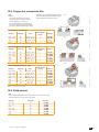
3. THE ATYS FAMILY PRODUCT RANGE . . . . . . . . . . . . . . . . . . . . . . . . . . . . . . . . . . . . . . . . . . . . . . . . . . . . .8
3.1. THE ATYS RANGE KEY FEATURES . . . . . . . . . . . . . . . . . . . . . . . . . . . . . . . . . . . . . . . . . . . . . . . . . . . . . . . . . .8
4. QUICK START . . . . . . . . . . . . . . . . . . . . . . . . . . . . . . . . . . . . . . . . . . . . . . . . . . . . . . . . . . . . . . . . . . . . . . . . . . . . . .10
. . . . . . . . . . . . . . . . . . . . . . . . . . . . . . . . . . . . .10
. . . . . . . . . . . . . . . . . . . . . . . . . . . . . . . . . . .14
!""#
. . . . . . . . . . . . . . . . . . . . . . . . . . . . . . . . . . . . . . . . . . . . . . . . . . . . . . . . . . . . . . . . . . . . .18
$%% . . . . . . . . . . . . . . . . . . . . . . . . . . . . . . . . . . . . . . . . . . . . . . . . . . . . . . . . . . . . . . . .18
$%% . . . . . . . . . . . . . . . . . . . . . . . . . . . . . . . . . . . . . . . . . . . . . . . . . . . . . . . . . . . . . . .19
!%!. . . . . . . . . . . . . . . . . . . . . . . . . . . . . . . . . . . . . . . . . . . . . . . . . . . . . . .20
"! . . . . . . . . . . . . . . . . . . . . . . . . . . . . . . . . . . . . . . . . . . . . . . . . . . . . . . . . . . . . . . . . . . . . . . . .21
5.4.1. IP RATING . . . . . . . . . . . . . . . . . . . . . . . . . . . . . . . . . . . . . . . . . . . . . . . . . . . . . . . . . . . . . . . . . . . . . . . . . . .21
5.4.2. OPERATING CONDITIONS . . . . . . . . . . . . . . . . . . . . . . . . . . . . . . . . . . . . . . . . . . . . . . . . . . . . . . . . . . . .21
5.4.3. STORAGE CONDITIONS . . . . . . . . . . . . . . . . . . . . . . . . . . . . . . . . . . . . . . . . . . . . . . . . . . . . . . . . . . . . . .21
. . . . . . . . . . . . . . . . . . . . . . . . . . . . .22
5.4.5. CE MARKING . . . . . . . . . . . . . . . . . . . . . . . . . . . . . . . . . . . . . . . . . . . . . . . . . . . . . . . . . . . . . . . . . . . . . . . .23
5.4.6. LEAD FREE PROCESS . . . . . . . . . . . . . . . . . . . . . . . . . . . . . . . . . . . . . . . . . . . . . . . . . . . . . . . . . . . . . . .23
5.4.7. WEEE . . . . . . . . . . . . . . . . . . . . . . . . . . . . . . . . . . . . . . . . . . . . . . . . . . . . . . . . . . . . . . . . . . . . . . . . . . . . . . .23
5.4.8. EMC STANDARD . . . . . . . . . . . . . . . . . . . . . . . . . . . . . . . . . . . . . . . . . . . . . . . . . . . . . . . . . . . . . . . . . . . . .23
"!! . . . . . . . . . . . . . . . . . . . . . . . . . . . . . . . . . . . . . . . . . . . . . . . . . . . . . . . . .24
!!
. . . . . . . . . . . . . . . . . . . . . . . . . . . . . . . . . . . . . . . . . . . . . . . . . . . . . . . . . . . . . . . . . . . . . . . . . . . . .25
$%% . . . . . . . . . . . . . . . . . . . . . . . . . . . . . . . . . . . . . . . . . . . . . . . . . . . . . . . . . . . . . . . . . .25
6.1.1. DIMENSIONS: FRAME B3 TO B5 (125A TO 630A). . . . . . . . . . . . . . . . . . . . . . . . . . . . . . . . . . . . . . . .25
6.1.2. DIMENSIONS: FRAME B6 & B7 (800A TO 1600A) . . . . . . . . . . . . . . . . . . . . . . . . . . . . . . . . . . . . . . . .26
6.1.3. DIMENSIONS: FRAME B8 (2000A TO 3200A) . . . . . . . . . . . . . . . . . . . . . . . . . . . . . . . . . . . . . . . . . . . .27
. . . . . . . . . . . . . . . . . . . . . . . . . . . . . . . . . . . . . . . . . . . . . . . . . . . . . . . . . . . . . . . . .28
!% . . . . . . . . . . . . . . . . . . . . . . . . . . . . . . . . . . . . . .28
6.3.1. BRIDGING BAR INSTALLATION . . . . . . . . . . . . . . . . . . . . . . . . . . . . . . . . . . . . . . . . . . . . . . . . . . . . . . . .28
6.3.2. TERMINAL SHROUDS . . . . . . . . . . . . . . . . . . . . . . . . . . . . . . . . . . . . . . . . . . . . . . . . . . . . . . . . . . . . . . . .29
6.3.3. TERMINAL SCREENS . . . . . . . . . . . . . . . . . . . . . . . . . . . . . . . . . . . . . . . . . . . . . . . . . . . . . . . . . . . . . . . .29
6.3.4. COPPER BAR CONNECTION KITS (2000A TO 3200A : FRAME B8) . . . . . . . . . . . . . . . . . . . . . . . .30
6.3.5. INCOMING COPPER BAR CONNECTION KIT ASSEMBLY . . . . . . . . . . . . . . . . . . . . . . . . . . . . . . . .31
6.3.6. OUTGOING BRIDGE CONNECTION ASSEMBLY . . . . . . . . . . . . . . . . . . . . . . . . . . . . . . . . . . . . . . . . .31
6.3.7. POWER SUPPLY . . . . . . . . . . . . . . . . . . . . . . . . . . . . . . . . . . . . . . . . . . . . . . . . . . . . . . . . . . . . . . . . . . . . .32
6.3.8. RAISED MOUNTING SPACERS . . . . . . . . . . . . . . . . . . . . . . . . . . . . . . . . . . . . . . . . . . . . . . . . . . . . . . . .32
EN
3
6.3.9. PADLOCKING KEY INTERLOCKS . . . . . . . . . . . . . . . . . . . . . . . . . . . . . . . . . . . . . . . . . . . . . . . . . . . . . .33
6.3.10. ADDITIONAL AUXILIARY CONTACTS. . . . . . . . . . . . . . . . . . . . . . . . . . . . . . . . . . . . . . . . . . . . . . . . . .33
7. CONNECTIONS
. . . . . . . . . . . . . . . . . . . . . . . . . . . . . . . . . . . . . . . . . . . . . . . . . . . . . . . . . . . . . . . . . . . . . . . . . . . .34
&$# . . . . . . . . . . . . . . . . . . . . . . . . . . . . . . . . . . . . . . . . . . . . . . . . . . . . . . . . . . . . . . . . . . . . . . . .34
7.1.1. CABLE OR BAR CONNECTIONS . . . . . . . . . . . . . . . . . . . . . . . . . . . . . . . . . . . . . . . . . . . . . . . . . . . . . .34
7.1.2. POWER CONNECTION TERMINALS . . . . . . . . . . . . . . . . . . . . . . . . . . . . . . . . . . . . . . . . . . . . . . . . . . .34
7.1.3. POWER CONNECTION CROSS-SECTION . . . . . . . . . . . . . . . . . . . . . . . . . . . . . . . . . . . . . . . . . . . . . .34
7.1.4. STANDARD CONNECTION PRIORITY SOURCE SUPPLY ON SWITCH I . . . . . . . . . . . . . . . . . . . .35
&#
%$#$!. . . . . . . . . . . . . . . . . . . . . . . . . . . . . . . . . . . . .36
7.2.1. TYPE OF NETWORKS . . . . . . . . . . . . . . . . . . . . . . . . . . . . . . . . . . . . . . . . . . . . . . . . . . . . . . . . . . . . . . . .36
7.2.2. METERING AND SENSING DETAILS . . . . . . . . . . . . . . . . . . . . . . . . . . . . . . . . . . . . . . . . . . . . . . . . . . .37
7.3. CONTROL CIRCUITS. . . . . . . . . . . . . . . . . . . . . . . . . . . . . . . . . . . . . . . . . . . . . . . . . . . . . . . . . . . . . . . . . . . . . .38
. . . . . . . . . . . . . . . . . . . . . . . . . . . . . . . . . . . . . . . . . . . . . . . . . . . . . . . . . . . . .38
. . . . . . . . . . . . . . . . . . . . . . . . . . . . . . . . . . . . . . . . . . . . . . .39
&"!%$#$$!
. . . . . . . . . . . . . . . . . . . . . . . . . . . . . . . . . . . . . . . . . . . . . .41
7.4.1. STANDARD CONFIGURATION . . . . . . . . . . . . . . . . . . . . . . . . . . . . . . . . . . . . . . . . . . . . . . . . . . . . . . . . .41
7.4.2. SENSING AND POWER SUPPLY KIT INSTALLATION (4 WIRE CONFIGURATION) . . . . . . . . . . . .42
7.4.3. SENSING KIT WIRING DIAGRAM (STANDARD) . . . . . . . . . . . . . . . . . . . . . . . . . . . . . . . . . . . . . . . . . .42
7.4.4. SENSING KIT WIRING DIAGRAM (SPECIFIC) . . . . . . . . . . . . . . . . . . . . . . . . . . . . . . . . . . . . . . . . . . . .43
$% . . . . . . . . . . . . . . . . . . . . . . . . . . . . . . . . . . . . . . . . . . . . . . . . . . . . . . . . . . . . . .46
!$ . . . . . . . . . . . . . . . . . . . . . . . . . . . . . . . . . . . . . . . . . . . . . . . . . . . . . . . . . . . . . . . . . . . . .47
8.1.1. EMERGENCY MANUAL OPERATION . . . . . . . . . . . . . . . . . . . . . . . . . . . . . . . . . . . . . . . . . . . . . . . . . . .47
8.1.2. PADLOCKING . . . . . . . . . . . . . . . . . . . . . . . . . . . . . . . . . . . . . . . . . . . . . . . . . . . . . . . . . . . . . . . . . . . . . . .47
!!$ . . . . . . . . . . . . . . . . . . . . . . . . . . . . . . . . . . . . . . . . . . . . . . . . . . . . . . . . . . . . . . . . .47
8.2.1. DUAL POWER SUPPLY . . . . . . . . . . . . . . . . . . . . . . . . . . . . . . . . . . . . . . . . . . . . . . . . . . . . . . . . . . . . . . .47
8.2.2. VOLTAGE SENSING INPUTS . . . . . . . . . . . . . . . . . . . . . . . . . . . . . . . . . . . . . . . . . . . . . . . . . . . . . . . . . .48
8.2.3. FIXED INPUTS . . . . . . . . . . . . . . . . . . . . . . . . . . . . . . . . . . . . . . . . . . . . . . . . . . . . . . . . . . . . . . . . . . . . . .49
8.2.4. FIXED OUTPUTS - DRY CONTACTS. . . . . . . . . . . . . . . . . . . . . . . . . . . . . . . . . . . . . . . . . . . . . . . . . . . .51
$ . . . . . . . . . . . . . . . . . . . . . . . . . . . . . . . . . . . . . . . . . . . . . . . . . . . . . . . . . . . . . . . . . . . . . . . . . .52
!" . . . . . . . . . . . . . . . . . . . . . . . . . . . . . . . . . . . . . . .53
!"
. . . . . . . . . . . . . . . . . . . . . . . . . . . . . . . . . .53
!" . . . . . . . . . . . . . . . . . . . . . . . . . . . . . . . . . . . . . . . . . . . . . . .54
8.3.4. STEP 4: SAVING THE CONFIGURED VALUES . . . . . . . . . . . . . . . . . . . . . . . . . . . . . . . . . . . . . . . . . . .54
!" . . . . . . . . . . . . . . . . . . . . . . . . . . . . . . . . .54
9. CHARACTERISTICS
. . . . . . . . . . . . . . . . . . . . . . . . . . . . . . . . . . . . . . . . . . . . . . . . . . . . . . . . . . . . . . . . . . . . . . .55
$"" . . . . . . . . . . . . . . . . . . . . . . . . . . . . . . . . . . . . . . . . . . . . . . . . . . . . . . . . . . . .58
!'% . . . . . . . . . . . . . . . . . . . . . . . . . . . . . . . . . . . . . . . . . . . . . . . . . . . . . . . . . . . .59
12. ACCESSORIES. . . . . . . . . . . . . . . . . . . . . . . . . . . . . . . . . . . . . . . . . . . . . . . . . . . . . . . . . . . . . . . . . . . . . . . . . . . .60
12.1. TERMINAL SHROUDS. . . . . . . . . . . . . . . . . . . . . . . . . . . . . . . . . . . . . . . . . . . . . . . . . . . . . . . . . . . . . . . . . . . .60
12.2. TERMINAL SCREENS . . . . . . . . . . . . . . . . . . . . . . . . . . . . . . . . . . . . . . . . . . . . . . . . . . . . . . . . . . . . . . . . . . . .60
% . . . . . . . . . . . . . . . . . . . . . . . . . . . . . . . . . . . . . . . . . . . . . . . . . . . . . . . . . . . . . . . . . . . . . . . .60
4
EN
$$
. . . . . . . . . . . . . . . . . . . . . . . . . . . . . . . . . . . . . . . . . . . . . . . . . . . . . . . .61
!%! . . . . . . . . . . . . . . . . . . . . . . . . . . . . . . . . . . . . . . . . . . . . . . . . . . . . . . . . . . . . . . . . . . . . . . . .61
(" . . . . . . . . . . . . . . . . . . . . . . . . . . . . . . . . . . . . . . . . . . . . . . . . . . . . . . .62
&%$#$$! . . . . . . . . . . . . . . . . . . . . . . . . . . . . . . . . . . . . . . . . . . . . . . . . . . . . . . . . . . . . . . . . . . . . .62
"!%$#$$!
. . . . . . . . . . . . . . . . . . . . . . . . . . . . . . . . . . . . . . . . . . . . .62
)"!! . . . . . . . . . . . . . . . . . . . . . . . . . . . . . . . . . . . . . . . . . . . . . . . . . . . . . . . . . . . . . . . . . . . . . . . .62
%$"% . . . . . . . . . . . . . . . . . . . . . . . . . . . . . . . . . . . . . . . . . . . . . . . . . . . . . . . .63
*!%%! . . . . . . . . . . . . . . . . . . . . . . . . . . . . . . . . . . . . . . . . . . . . . . . . . . . .63
12.12. MOUNTING SPACERS . . . . . . . . . . . . . . . . . . . . . . . . . . . . . . . . . . . . . . . . . . . . . . . . . . . . . . . . . . . . . . . . . .63
$$%!
++ . . . . . . . . . . . . . . . . . . . . . . . . . . . . . . . . . . . . . . . . . . . . . . . . . . . . . .63
12.14. RONIS KEY INTERLOCKING SYSTEM . . . . . . . . . . . . . . . . . . . . . . . . . . . . . . . . . . . . . . . . . . . . . . . . . . . .64
. . . . . . . . . . . . . . . . . . . . . . . . . . . . . . . . . . . . . . . . . . . . . . . . . . . . . . . . . . . . . . . . . . .64
! . . . . . . . . . . . . . . . . . . . . . . . . . . . . . . . . . . . . . . . . .64
&!!" . . . . . . . . . . . . . . . . . . . . . . . . . . . . . . . . . . . . . . . . . . . . . . . . . . . . . . . . . . . . . . . . . . . . .64
(!
! . . . . . . . . . . . . . . . . . . . . . . . . . . . . . . . . . . . . . . . . . . . . . . . . . . . . . . . .64
13. SPARE PARTS
. . . . . . . . . . . . . . . . . . . . . . . . . . . . . . . . . . . . . . . . . . . . . . . . . . . . . . . . . . . . . . . . . . . . . . . . . . . .65
13.1. ELECTRONIC MODULE . . . . . . . . . . . . . . . . . . . . . . . . . . . . . . . . . . . . . . . . . . . . . . . . . . . . . . . . . . . . . . . . . .65
13.2. MOTORISATION MODULE . . . . . . . . . . . . . . . . . . . . . . . . . . . . . . . . . . . . . . . . . . . . . . . . . . . . . . . . . . . . . . . .65
$# . . . . . . . . . . . . . . . . . . . . . . . . . . . . . . . . . . . . . . . . . . . . . . . . . . . . . . . . . . . . . . . . . . . . . . .65
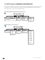
14. ATYS FAMILY: ORDERING INFORMATION
. . . . . . . . . . . . . . . . . . . . . . . . . . . . . . . . . . . . . . . . . . . . . .66
EN
1. GENERAL SAFETY INSTRUCTIONS
This manual provides instructions on safety, connections and operation of the ATy!
"#$#%&'
Whether the ATy(()#*)*((#&
+#*!#("&%((%&-#(+.)
personnel, in line with the manufacturers recommendations, following good engineering practices and after
!#((($(!)###('
)#&-#)(#%#(!
)#%)$%&-#(&-#(+)('
)#))"(%($$/(#))+
)#$'#($)/)#)((
$!(#()+)#'
0
)##)*##
)+(#)(1#&2-#)'
This instruction manual must be made accessible so as to be easily available to anyone who may need to
read it in relation with the ATy'
The ATy#)3!!&)$)#(#/
)#'
No covers on the ATy#(%)4""#!(5&((%#!(
)##$.(#'
6
(")##&*(/*%#'7&#&
"/(!))!&$.)(!)*#
"(#(((#8'
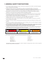
DANGER
WARNING
CAUTION
RISK:
RISK:
RISK:
Electric shock, burns, death
Possible personal injury
Equipment damage
As a minimum the ATy)(&"$(("(9
:;<=;
:;<=B
><?
:B=B
@;<=;
@;<=B
63<;;<<=
@@@;<=B
@;<=;
@;<=B
@@@;<=;
$)!##(#%1"#*$(
$(&#('
EN
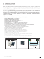
2. INTRODUCTION
ATyC#$"-#)D45$#)"&$$$
$(#))(&%"((#'!)"
##))(&#)#$#$#(()(":;<=;*><?
(('
The ATy$#(((%/4"&)5!$"-#)")
)!(&!($#(+((-#:;<=B'
(7*y)%($C/"##D:;<=
B #(8 $ #) FB* > <?* : ;<=; -#!( " #(8
$#)BB'
ATy
7"($&%"((#'
)()#(!$#((&%((#'
:#!G:$&2(()'
:%#"'
H""((&!%():I<::'
$($((/'
%()4:I<I::5$$%&&)(!%/'
)#$$%&"/!('
&$+"!#((&#)"((*($$)'
J#/*&$#(C(D&#()'
(Manual operation is functional with and without the motorization in place).
.(&#*$%#()(/$(&'
$"(("$$!'
("")%(&)$&'
)(#8($"('
$"+#$&$'
:")#.(&'
3#(!C)#!(%(&D#$%/$(('
)(#)+-#'
K#((&(()+((&$2>))('
7"#))(&#&$"/4$5))('''
,-/0(,-/0
Automatic transfert Switch
3<
ATyS t
LOAD
EN
7
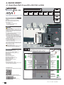
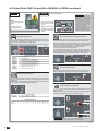
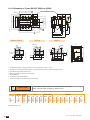
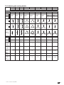
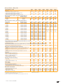
3. THE ATyS FAMILY PRODUCT RANGE
The ATy%%&$.((K"%L!&"#
<<6#)"(%%&KM"/))"9O**0P*
**P(&LM$))*##6Q*R7*U0*>MV'
%#$#)"($&)#FF'+
C!"D"#<&y%%#%&1
)(&)"#&"("'
The ATy K(& (# )( $ (& ) $ " -#) 4M5 "(( #$#((&)#(#45'(yS will depend on the application as
well as the nature of installation in which the ATy"((%(('
##((#(#)+CyD(&'K((yS family
$)#)($)+##(()#'
4!(%($"("""''5
An overview of the complete ATyS range is presented below:
(The encircled device is the product detailed in this instruction manual).
Just the right ATyS for your application…
40A - 160A
ATyS M: Modular Profile
125A - 3200A
ATyS: Small Footprint
58
7"2>
58
!(!>
//
$#
new
40A - 125A
5;
)(>
56
((>
"37
54M5
((>
45
5<
Transformer
56
M4375
5=
M
45
ATyS
M
5;
)(>
5<
$4%#(5
56
M4375
Side by Side
$#
0P!$&!(%($<<<<
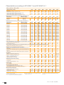
3.1. The ATy!"
Selecting the right ATyS will depend on the application, the functionality required as well as the nature of the installation
in which the ATy"((%(('("#()#((/&$#$)#
to help to select the right ATy$&#'
EN
:;<=;
ATyS S
ATyS Sd
#(&)".((
H%(!(#))(&
H%3(!(#))(&
#
#
#
#
#
#
#
#
#
#
#
#
#
<I
F
<I
F
0P<<
I<<
#
#
#
#
#
#
#
#
#
#
#
#
#
#
#
#
#
#
#
#
#
#
#
#
#
#
#
#
#
#
#
#
#
#
#
#
#
#
#
#
#
#
#
#
#
2
#
2
#2F
#2B
#
2F
#;2
#?2?
#
#
#
#
#
M3)(&#(MR
$3<
:3#()"#))(&
@"/>))(
>>))(
ATyS p
#
#
#
#!(%(&P3)(&
@"/@"/))(
ATyS g
#
#
#
!($"84$$5)
:)#.(&4:::5
ATyS t
#
#
#
#
Watchdog relay to ensure product availability
M$<IF
F
BF<<$
ATyS d
ATyS
0P<<?
!"(!%&&
ATyS r
7$$.:2
#
7%(:2
()%(:2#(4)(#)#(5
M(&)$"-#)
4M(75
#
#
#
#
#
#
#
#
#$"-#)4(75
MX#((
#XMX#((
#XMXP(X#((
#$#$!($-#&(!(
"7P3)(&
#&(!
$##))"
Test on load functionality
Test off load functionality
7%($#"/&)P3)(&
Y#9/HZ/6Z/6X/HZ/6Z/6
#M?
XX"&4)(5
H%!#)(#(4)(5
&$#$"4#2%#5
M(0MR
$3F<
#
#
#
#
#
#
#
#
#
#
#
#
#
#
#
#
#
#
#
#
#
#
#
#
3P$!M"M
4#2%#5
7%(.$#(&
4#2%#5
#
#((!()"
#
#
#
#
#
#
#
#
#
P$#
)&$#(&
7/!$#(&
F<##(4)(5
OH7#(#)##(4)(5
#OH*)#V
P3)(&$)**#
7%(&)($#(&
#
EN
9
4. $%&'!
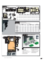
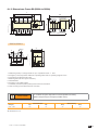
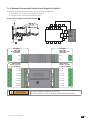
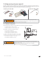
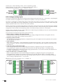
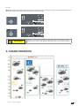
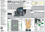
4.1. Quick Start ATy"()(*+,/*7)89
STEP 7A
Installation and Commissioning
QUICK START
EN
AUT Mode
(Automatic Control)
ATyS t
STEP 1
STEP 2
STEP 3
STEP 4
STEP 5
STEP 6
Cabinet / Back
Plate Installation
Power Terminal
Connections
COMMAND /
CONTROL terminal
connections
Power SUPPLY and
ATS Controller
Terminal
Connections
CHECK
PROGRAMMING
STEP 7B
AUT Mode
(Remote Control)
Motorised Source Changeover Switch
STEP 7C
Automatic Transfer Switching Equipment
Manual Mode
Preliminary operations
Check the following upon delivery and after removal of the
packaging:
■ Packaging and contents are in good condition.
■ The product reference corresponds to the order.
■ Contents should include:
Qty 1 x ATyS t
Qty 1 x Emergency handle and fixing clip
Quick Start instruction sheet
STEP 7D
Padlocking Mode
STEP 4
Warning
Risk of electrocution, burns or injury to persons and /
or damage to equipment.
This Quick Start is intended for personnel trained in the
installation and commissioning of this product. For further
details refer to the product instruction manual available on
the SOCOMEC website.
■ This product must always be installed and commissioned
by qualified and approved personnel.
■ Maintenance and servicing operations should be
performed by trained and authorised personnel.
■ Do not handle any control or power cables connected to
the product when voltage may be, or may become present
on the product, directly through the mains or indirectly
through external circuits.
■ Always use an appropriate voltage detection device to
confirm the absence of voltage.
■ Ensure that no metal objects are allowed to fall in the
cabinet (risk of electrical arcing).
Clip for
storage of
the
emergency
handle
Failure to observe good enginering practises as well as to
follow these safety instructions may expose the user and
others to serious injury or death.
Risk of damaging the device
■ In case the product is dropped or damaged in any way it
is recommended to replace the complete product.
Power Supply, Sensing and Control wiring (ATS Controller)
2
Connect the product with a cable of section of 1,5 to 2,5 mm .
Screw M3 - Tightening torque: min.: 0.5 Nm - max.: 0.6 Nm
ATS Power Supply
Power supply II - L
Power supply II - N
50/60 Hz
Power 208-277V~ +/-20%
For further details refer to the product instruction manual
under chapter "Spares and Accessories"
STEP 4
Power 208-277V~ +/-20%
Accessories
■ Bridging bars and connection kits.
■ Control voltage transformer (400Vac -> 230Vac).
■ DC power supply (12/24Vdc -> 230Vac).
■ Mounting spacers to raise the product x 10mm.
■ Phase barriers.
■ Terminal shrouds.
■ Terminal screens.
■ Auxiliary contacts (Additional).
■ Padlocking in 3 positions (I - O - II).
■ Lockout accessories (RONIS - EL 11 AP).
■ Door escutcheon frame.
■ ATyS D10 Interface (remote display).
■ Voltage sensing kit.
■ Sealable cover.
■ RJ45 cable for ATyS D10 => ATyS t
STEP 3
ATS Power Supply
Power supply I - L
Power supply I - N
50/60 Hz
ATS Voltage Sensing
Input
Source supply I
S I - Phase 1
S I - Phase 2
S I - Phase 3
600 VAC (ph-ph) max
ATS Voltage Sensing
Input
Source supply II
S II - Phase 1
S II - Phase 2
S II - Phase 3
600 VAC (ph-ph) max
S I - Neutral
332 VAC (ph-n) max
S II - Neutral
332 VAC (ph-n) max
www.socomec.com
Recommanded to use SOCOMEC
Voltage Sensing Kit
(refer to ATyS t
accessories
for details)
541 993 C - 02/14 - EN
EN
To D10
Printing informations: 1 color Black. White paper 90g/m2.
Printing size: 420x297. Final size 210x297. This page visible first.
A separate sheet for each language.
64B 63B
417 416 415 414 413
To download, brochures, catalogues and technical manuals:
ATS Module
Control Inputs
(Fixed)
ATS Module
Output Contact
(Product available)
Remote interface
RJ45 - to ATyS D10
Non contractual document.
Subject to change without notice.
Recommended
orientation
M
Ok
=
Ok
J1
=
Caution:
Ensure that
the product is
installed on a
flat rigid
surface.
Dimensions in mm.
Installation
Fix. 195
Fix. 180
STEP 1
Door cut-out for front panel.
138
T
165
Fix. 195
Fix. 180
20
C
U
21
Ø7
125 A
Ø9
CA
50.5
W
U
J1
M
T
C
U
W
CA
160 A
200 A
250 A
315 A
400 A
500 A
630 A
3P
4P
3P
4P
3P
4P
3P
4P
3P
4P
3P
4P
3P
4P
3P
4P
34
120
36
244
20
9
10
34
150
36
244
20
9
10
34
120
36
244
20
9
10
34
150
36
244
20
9
10
34
120
36
244
20
9
10
34
150
36
244
20
9
10
35
160
50
244
25
11
15
35
210
50
244
25
11
15
35
160
50
244
35
11
15
35
210
50
244
35
11
15
35
160
50
244
35
11
15
35
210
50
244
35
11
15
34
210
65
320
32
13
20
34
270
65
320
32
13
20
34
210
65
320
45
13
20
34
270
65
320
45
13
20
STEP 2
Power Terminal Connections
To be connected using terminal lugs, rigid or flexable busbars.
FRAME B3
Minimum cable section Cu (mm2) at Ith
Minimum cable section Cu (mm2) at Ith
Maximum cable
section Cu (mm2)
Maximum Cu busbar
width (mm)
Type of screw
Recommended tightening torque (N.m)
Maximum tightening
torque (N.m)
FRAME B4
FRAME B5
125 A
160 A
200 A
250 A
315 A
400 A
500 A
630 A
50
70
95
120
185
240
2x150
2x185
-
-
-
-
-
-
2x30x5
2x40x5
50
95
150
150
240
240
2x300
2x300
20
20
32
32
32
32
50
50
M8
M8
M8
M10
M10
M10
M12
M12
8.3
8.3
8.3
20
20
20
20
20
13
13
13
26
26
26
26
26
STEP 3
Example: Control wiring for a 400VAC application having a 3 phase and neutral supply.
CONTROL / COMMAND Terminals
Ensure that the product is in Manual Mode.
1
2
1
F2
N
L1
L1
N
64B 63B 417 416 415 414 413
L3
16
L2
L3
L2
203 204 205 206
16
11
10
6
312 313 314 315 316 317
106 105 104 103
17
15
14
13
12
10. O/P to ATyS D10 remote display
11. Product Available output (ATS)
12. I/P Inhibition of the ATS controls
1. Position 0 order
13. I/P Manual retransfer (RTC)
2. Position I order
14. I/P to define the source priority:
3. Position II order
Source priority set to S2 if closed,
4. Zero position priority order
S1 if open
5. Remote Control Enable (Priority over 15. I/P with/without source priority:
Auto)
#)&"(
6. Product Available output (Motor)
16. Voltage Sensing Inputs
7. Position II aux contact
17. Power Supply Inputs
8. Position I aux contact
9. Position 0 aux contact
1 preferred source
2 alternate source
7 8 9
63A 64A 24 14 04 13
5 4 3 2 1
2
RJ
201 202
17
102 101
F1
ATyS D10
Remote
Display Unit
EN
11
:,$;"()(*+,/*7)89
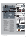
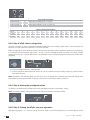
STEP 6
Power 208-277V~
+/-20%
Check
Whilst in manual mode, check the
wiring and if ok power up the
product.
Power 208-277V~ +
+/-20%
STEP 5
Programming the ATyS t
WARNING As a safety measure
the READY LED will flash when any of the
settings shown on the controller are different
to those that are saved. To return to the steady
READY LED revert to the saved setting values
or save the displayed value by pressing the
PROG OK button briefly. (This is intended as
a visual alarm in case one has changed the
configuration settings but has not yet saved
the new values in the product).
For added security the ATyS t may be
equipped with a sealable cover so as to limit
the access to configuration settings. Refer
to the product accessory section for details.
The ATyS t is programmed after
wiring verification tests through
the front of the ATS Controller
in 5 steps:
LED “Power” Green: ON
Note: Ensure that the ATyS t is
in “Manual Mode”, powered and
with at least one network supply
available.
LED Manuel/Fault Red: ON
Dip Switch Setting Options
Auto Configuration of Mains Voltage and Frequency
SET the 4 Dip Switches using a small screw driver. Possible variants vary from positions “A to
H” as described in the table below. For convenience, the position functions are also described
on the front of the ATS controller adjacent to the dip switches.
Note: The READY LED will flash green as soon as settings are changed and until the new settings
have been saved by pressing the PROG OK button momentarily.
READY
R
A:
B:
OTE CONTRO
PROG
OK
C:
D:
The ATyS t includes an “Auto Configuration” feature to detect the mains voltage and frequency
nominal values, phase rotation and neutral position and saves them in the ATS controller.
Note: Before configuring the nominal values ensure that the product is properly wired, verified
and ready for commissioning. It is imperative that the network supply is available and that the
wiring to the ATyS t voltage sensing terminals 103 – 106 and 203 – 206 has been done. It is
preferable to use the ATyS sensing kit that may be provided as an accessory.
!#
$&
'
*
!"#"$"%$&'*+
READY LED will flash green as soon as settings are measured and until these settings have been
saved by pressing the PROG OK button a second time momentarily. (Refer to STEP 4).
READY
R
Dip Switch Setting Options
A
B
Dipswitch 1
A/B
C
Dipswitch 2
C/D
D
E
F
G
H
Dipswitch 3
E/F
Dipswitch 4
G/H
Three Phase Network
Single Phase Network
(Attn : Dipswitch 2 is inactive in this position)
Three Phase 4 wire Network (Including Neutral)
(Allows to detect a loss of neutral for unbalanced loads)
Three Phase 3 wire Network (Without Neutral)
Without a time delay in Zero Position (DBT = 0 sec)
Zero position time delay set to 2s (DBT = 2 sec)
Threshold Delta U : 10% / Delta F : 5%
Threshold Delta U : 20% / Delta F : 10%
A:
B:
REMOTE CONTROL
AUT
PROG
OK
C:
D:
Saving the configured values
To SAVE the recorded setting configuration press the PROG OK button momentarily: <60ms.
Note: The flashing READY LED goes off once the values are saved in the ATS controller.
READY
Potentiometer Setting Options
A:
B:
REMOTE CONTROL
SET the 2 potentiometers using a small screw driver paying attention to the arrow indicating
the position. There are a total of 14 positions for which the specific settings are described in
the table below.
Note: The READY LED will flash green as soon as settings are changed and until the new settings
have been saved by pressing the PROG OK button momentarily.
5
1
0
5
10 1
0
20
60
AUT
PROG
OK
C:
D:
Putting the ATyS t into Auto Operation
10
20
After following Steps 1 to 4, and once ready to put the ATyS t into AUTO operation turn the mode
selector switch to Auto.
Note: When the product is powered and properly configured, after switching the product from
Manual Mode to Auto Mode the READY light should be a steady green light.
60
Functional Description
5
1
0
Potentiometer 1
FT
Supply Source Failure time : 0 to 60s
Potentiometer 2
RT
Supply Source Return Time : 0 to 60 min
5
10 1
0
10
20
60
20
60
Position Setting Identification
Pos. N°
FT (sec)
RT (min)
1
0
0
2
1
1
3
2
2
4
3
3
5
4
4
6
5
5
7
8
8
8
10
10
9
15
15
10
20
20
11
30
30
12
40
40
13
50
50
14
60
60
READY
REMOTE CONTROL
AUT
PROG
OK
A: 3 Ph
B: 1 Ph
E:
F:
C: Neutral
D: Neutral
G: U 10% F 5%
H: U 20% F 10%
5
1
0
5
10 1
0
10
20
60
20
60
READY
REMOTE CONTROL
AUT
PROG
OK
A: 3 Ph
B: 1 Ph
E:
F:
C: Neutral
D: Neutral
G: U 10% F 5%
H: U 20% F 10%
WARNING Depending on the state of the ATyS t the ATS automation may change the switch
position as soon as the mode selector is switched to AUT. This is a normal operation.
12
EN
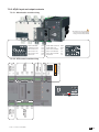
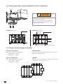
STEP 7A
6
7
8
9
10
AUT Mode
REMOTE CONTROL
AUT
Ensure that the emergency handle is
not inserted in the product and turn
the mode selector to the AUT position.
LED “Power” Green: ON
LED Manuel/Default: OFF
11
5
STEP 7B
4
AUT Mode
12
13
14
3
Impulse logic
REMOTE CONTROL
AUT
Contactor logic
order I
order 0
order II
2
15
1
16
position I
position 0
position II
;?@[
22
17
21
maintened
To enable control, close contact 312 with 317.
For contactor logic bridge contact 316 with 317.
To operate: close the contact corresponding to
the desired position.
To force the product to 0 position “OFF” bridge
contact 313 with 317.
18
STEP 7C
9 0°
20
1. MANUAL Mode LED indication.
(Yellow steady light when in Manual Mode).
2. AUTO Mode LED indication
Green steady light when in Auto mode with
no timers running.
Green flashing light when in Auto with timers
running in the background.
3. REMOTE CONTROL Mode LED indication.
Yellow steady light when in remote control
mode.
Remote control mode is achieved with the
Auto/Manu selector switched to Auto and
terminals 312 closed with terminal 317.
Remote control orders are received through
closing 314 to 316 with 317.
4. Switch 1 LED position indication.
(Green when in position 1).
5. Source supply I availability LED indication.
(Green when supply I voltage is within the
set limits).
6. Zero position LED indication.
(Yellow when in position 0).
7. Switch 2 LED position indication.
(Green when in position 2).
8. Source supply II availability LED indication.
(Green when supply II voltage is within the
set limits).
9. Sealing screw location 1 for use with sealing
cover (Available as an accessory)
10. Potentiometer 1: Supply FAILURE Time (FT)
Adjustable from 0 to 60 seconds.
11. Potentiometer 2: Supply RETURN Time (RT)
Adjustable from 0 to 60 minutes.
19
12. READY LED indication
Green steady light : Product in AUTO,
Watchdog OK, Product Available to
changeover.
Green flashing: Settings displayed not
saved or have been changed since last
saved.
(Press PROG OK button in manual mode to
save or revert to last saved settings).
13. Sealing screw location 2 for use with the
sealing cover.
14. FAULT LED indication. (Red steady light in
case of an ATS controller internal fault).
15. Configuration dip switches :
(4 dip switches with 2 positions in each
A to H).
16. PROG OK: Configuration save push button.
(ATTN: Active in Manual Mode ONLY).
Press briefly to confirm and save all set
configuration settings.
Hold pressed for 2 seconds to set the
network supply voltage and frequency by
Auto Configuration.
This is to be followed by pressing briefly to
save the set value configured.
17. Green LED Indication: Power
18. Red LED Indication: Product Unavailable /
Manual Mode / Fault Condition
19. Auto / Manual mode selector switch
(Key version available as an option)
20. Padlocking facility
(Up to 3 padlocks of dia. 4 – 8mm)
21. Emergency manual operation shaft location
(Accessible only in manual mode)
22. Switch position indication window:
I (On switch I) O (Off) II (On switch II).
0
90
°
I
STEP 7D
REMOTE CONTROL
Manual Mode
AUT
AUT
II
Padlocking Mode
(as standard : in position O)
EN
13
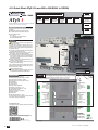
4.2. Quick Start ATy"(7(<+<88)/889
STEP 7A
Installation and Commissioning
QUICK START
EN
AUT Mode
(Automatic Control)
ATyS t
STEP 1
STEP 2
STEP 3
STEP 4
STEP 5
STEP 6
Cabinet / Back
Plate Installation
Power Terminal
Connections
COMMAND /
CONTROL terminal
connections
Power SUPPLY and
ATS Controller
Terminal
Connections
CHECK
PROGRAMMING
STEP 7B
AUT Mode
(Remote Control)
Motorised Source Changeover Switch
STEP 7C
Automatic Transfer Switching Equipment
Manual Mode
Preliminary operations
Check the following upon delivery and after removal of the
packaging:
■ Packaging and contents are in good condition.
■ The product reference corresponds to the order.
■ Contents should include:
Qty 1 x ATyS t
Qty 1 x Emergency handle and fixing clip
Quick Start instruction sheet
STEP 7D
Padlocking Mode
STEP 4
Warning
Risk of electrocution, burns or injury to persons and /
or damage to equipment.
This Quick Start is intended for personnel trained in the
installation and commissioning of this product. For further
details refer to the product instruction manual available on
the SOCOMEC website.
■ This product must always be installed and commissioned
by qualified and approved personnel.
■ Maintenance and servicing operations should be
performed by trained and authorised personnel.
■ Do not handle any control or power cables connected to
the product when voltage may be, or may become present
on the product, directly through the mains or indirectly
through external circuits.
■ Always use an appropriate voltage detection device to
confirm the absence of voltage.
■ Ensure that no metal objects are allowed to fall in the
cabinet (risk of electrical arcing).
Clip for
storage of
the
emergency
handle
Failure to observe good enginering practises as well as to
follow these safety instructions may expose the user and
others to serious injury or death.
Risk of damaging the device
■ In case the product is dropped or damaged in any way it
is recommended to replace the complete product.
Power Supply, Sensing and Control wiring (ATS Controller)
2
Connect the product with a cable of section of 1,5 to 2,5 mm .
Screw M3 - Tightening torque: min.: 0.5 Nm - max.: 0.6 Nm
ATS Power Supply
Power supply II - L
Power supply II - N
50/60 Hz
Power 208-277V~ +/-20%
For further details refer to the product instruction manual
under chapter "Spares and Accessories"
STEP 4
Power 208-277V~ +/-20%
Accessories
■ Bridging bars and connection kits.
■ Control voltage transformer (400Vac -> 230Vac).
■ DC power supply (12/24Vdc -> 230Vac).
■ Mounting spacers to raise the product x 10mm.
■ Phase barriers.
■ Terminal shrouds.
■ Terminal screens.
■ Auxiliary contacts (Additional).
■ Padlocking in 3 positions (I - O - II).
■ Lockout accessories (RONIS - EL 11 AP).
■ Door escutcheon frame.
■ ATyS D10 Interface (remote display).
■ Voltage sensing kit.
■ Sealable cover.
■ RJ45 cable for ATyS D10 => ATyS t
STEP 3
ATS Power Supply
Power supply I - L
Power supply I - N
50/60 Hz
ATS Voltage Sensing
Input
Source supply I
S I - Phase 1
S I - Phase 2
S I - Phase 3
600 VAC (ph-ph) max
ATS Voltage Sensing
Input
Source supply II
S II - Phase 1
S II - Phase 2
S II - Phase 3
600 VAC (ph-ph) max
S I - Neutral
332 VAC (ph-n) max
S II - Neutral
332 VAC (ph-n) max
www.socomec.com
Recommanded to use SOCOMEC
Voltage Sensing Kit
(refer to ATyS t
accessories
for details)
541 994 D - 02/14 - EN
14
EN
To D10
Printing informations: 1 color Black. White paper 90g/m2.
Printing size: 420x297. Final size 210x297. This page visible first.
64B 63B
417 416 415 414 413
To download, brochures, catalogues and technical manuals:
ATS Module
Control Inputs
(Fixed)
ATS Module
Output Contact
(Product available)
Remote interface
RJ45 - to ATyS D10
Non contractual document.
Subject to change without notice.
STEP 1
Recommended
orientation
Ok
=
280
250
Ok
=
Caution:
Ensure that the
product is installed on
a flat rigid surface.
Dimensions
in mm.
ATyS t 800 to 1600 A
51,5
M
Installation
138
C
T
20
Door cut-out for
front panel.
21
ATyS t 2000 to 3200 A
51.5
50.5
250
214
M
ATyS t 800 to 1000 A
ATyS t 1250 A
ATyS t 1600 to 3200 A
ø12.5
5
16 x 11
ø9
5
8.5
33
8.5
15.75
28.5
800 A
12.5
15
15 28.5
10 33
ø 15
M
25 25
30
30
45
45
90
15.75
60
50
C
T
1000 A
1250 A
1600 A
2000 A
21
2500 A
3200 A
3P
4P
3P
4P
3P
4P
3P
4P
3P
4P
3P
4P
3P
4P
255
335
255
335
255
335
347
467
347
467
347
467
347
467
T
80
80
80
80
80
80
120
120
120
120
120
120
120
120
C
391
391
391
391
391
391
391
391
523
523
523
523
523
523
STEP 2
Power Terminal Connections
To be connected using terminal lugs, rigid or flexable busbars.
FRAME B6
Minimum cable section
Cu (mm2) at Ith
Minimum cable section
Cu (mm2) at Ith
Maximum cable section
Cu (mm2)
Maximum Cu busbar
width (mm)
Type of screw
Recommended tightening torque (N.m)
Maximum tightening
torque (N.m)
FRAME B7
1000 A
1250 A
1600 A
2000 A
2500 A
2x240
-
-
-
-
-
-
2x50x5
2x60x5
2x80x5
2x100x5
3x100x5
4x100x5
3x100x10
2x300
4x185
4x185
6x185
-
-
-
63
63
63
100
100
100
100
M8
M8
M10
M12
M12
M12
M12
20
20
20
40
40
40
40
26
26
26
45
45
45
45
STEP 3
Example: Control wiring for a 400VAC application having a 3 phase and neutral supply.
FRAME B8
800 A
3200 A
CONTROL / COMMAND Terminals
Ensure that the product is in Manual Mode.
1
2
F2
N
L1
L1
N
64B 63B 417 416 415 414 413
L3
16
L2
L3
L2
203 204 205 206
16
11
10
6
312 313 314 315 316 317
2
15
14
13
12
10. O/P to ATyS D10 remote display
11. Product Available output (ATS)
12. I/P Inhibition of the ATS controls
1. Position 0 order
13. I/P Manual retransfer (RTC)
2. Position I order
14. I/P to define the source priority:
3. Position II order
Source priority set to S2 if closed,
4. Zero position priority order
S1 if open
5. Remote Control Enable (Priority over 15. I/P with/without source priority:
Auto)
#)&"(
6. Product Available output (Motor)
16. Voltage Sensing Inputs
7. Position II aux contact
17. Power Supply Inputs
8. Position I aux contact
9. Position 0 aux contact
1 preferred source
2 alternate source
7 8 9
63A 64A 24 14 04 13
5 4 3 2 1
1
106 105 104 103
17
RJ
201 202
17
102 101
F1
ATyS D10
Remote
Display Unit
EN
:/$;"(7(<+<88)/889
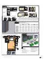
STEP 6
Power 208-277V~
+/-20%
Check
Whilst in manual mode, check the
wiring and if ok power up the
product.
Power 208-277V~ +
+/-20%
STEP 5
Programming the ATyS t
WARNING As a safety measure
the READY LED will flash when any of the
settings shown on the controller are different
to those that are saved. To return to the steady
READY LED revert to the saved setting values
or save the displayed value by pressing the
PROG OK button briefly. (This is intended as
a visual alarm in case one has changed the
configuration settings but has not yet saved
the new values in the product).
For added security the ATyS t may be
equipped with a sealable cover so as to limit
the access to configuration settings. Refer
to the product accessory section for details.
The ATyS t is programmed after
wiring verification tests through
the front of the ATS Controller
in 5 steps:
LED “Power” Green: ON
Note: Ensure that the ATyS t is
in “Manual Mode”, powered and
with at least one network supply
available.
LED Manuel/Fault Red: ON
Dip Switch Setting Options
Auto Configuration of Mains Voltage and Frequency
SET the 4 Dip Switches using a small screw driver. Possible variants vary from positions “A to
H” as described in the table below. For convenience, the position functions are also described
on the front of the ATS controller adjacent to the dip switches.
Note: The READY LED will flash green as soon as settings are changed and until the new settings
have been saved by pressing the PROG OK button momentarily.
READY
R
A:
B:
OTE CONTRO
PROG
OK
C:
D:
The ATyS t includes an “Auto Configuration” feature to detect the mains voltage and frequency
nominal values, phase rotation and neutral position and saves them in the ATS controller.
Note: Before configuring the nominal values ensure that the product is properly wired, verified
and ready for commissioning. It is imperative that the network supply is available and that the
wiring to the ATyS t voltage sensing terminals 103 – 106 and 203 – 206 has been done. It is
preferable to use the ATyS sensing kit that may be provided as an accessory.
!#
$&
'
*
!"#"$"%$&'*+
READY LED will flash green as soon as settings are measured and until these settings have been
saved by pressing the PROG OK button a second time momentarily. (Refer to STEP 4).
READY
R
Dip Switch Setting Options
A
B
Dipswitch 1
A/B
C
Dipswitch 2
C/D
D
E
F
G
H
Dipswitch 3
E/F
Dipswitch 4
G/H
Three Phase Network
Single Phase Network
(Attn : Dipswitch 2 is inactive in this position)
Three Phase 4 wire Network (Including Neutral)
(Allows to detect a loss of neutral for unbalanced loads)
Three Phase 3 wire Network (Without Neutral)
Without a time delay in Zero Position (DBT = 0 sec)
Zero position time delay set to 2s (DBT = 2 sec)
Threshold Delta U : 10% / Delta F : 5%
Threshold Delta U : 20% / Delta F : 10%
A:
B:
REMOTE CONTROL
AUT
PROG
OK
C:
D:
Saving the configured values
To SAVE the recorded setting configuration press the PROG OK button momentarily: <60ms.
Note: The flashing READY LED goes off once the values are saved in the ATS controller.
READY
Potentiometer Setting Options
A:
B:
REMOTE CONTROL
SET the 2 potentiometers using a small screw driver paying attention to the arrow indicating
the position. There are a total of 14 positions for which the specific settings are described in
the table below.
Note: The READY LED will flash green as soon as settings are changed and until the new settings
have been saved by pressing the PROG OK button momentarily.
5
1
0
5
10 1
0
20
60
AUT
PROG
OK
C:
D:
Putting the ATyS t into Auto Operation
10
20
After following Steps 1 to 4, and once ready to put the ATyS t into AUTO operation turn the mode
selector switch to Auto.
Note: When the product is powered and properly configured, after switching the product from
Manual Mode to Auto Mode the READY light should be a steady green light.
60
Functional Description
5
1
0
Potentiometer 1
FT
Supply Source Failure time : 0 to 60s
Potentiometer 2
RT
Supply Source Return Time : 0 to 60 min
5
10 1
0
10
20
60
20
60
Position Setting Identification
Pos. N°
FT (sec)
RT (min)
1
0
0
2
1
1
3
2
2
4
3
3
5
4
4
6
5
5
7
8
8
8
10
10
9
15
15
10
20
20
11
30
30
12
40
40
13
50
50
14
60
60
READY
REMOTE CONTROL
AUT
PROG
OK
A: 3 Ph
B: 1 Ph
E:
F:
C: Neutral
D: Neutral
G: U 10% F 5%
H: U 20% F 10%
5
1
0
5
10 1
0
10
20
60
20
60
READY
REMOTE CONTROL
AUT
PROG
OK
A: 3 Ph
B: 1 Ph
E:
F:
C: Neutral
D: Neutral
G: U 10% F 5%
H: U 20% F 10%
WARNING Depending on the state of the ATyS t the ATS automation may change the switch
position as soon as the mode selector is switched to AUT. This is a normal operation.
EN
STEP 7A
6
7
8
9
10
AUT Mode
REMOTE CONTROL
AUT
Ensure that the emergency handle is
not inserted in the product and turn
the mode selector to the AUT position.
LED “Power” Green: ON
LED Manuel/Default: OFF
11
5
STEP 7B
4
AUT Mode
12
13
14
3
Impulse logic
REMOTE CONTROL
AUT
Contactor logic
order I
order 0
order II
2
15
1
16
position I
position 0
position II
;?@[
22
17
21
maintened
To enable control, close contact 312 with 317.
For contactor logic bridge contact 316 with 317.
To operate: close the contact corresponding to
the desired position.
To force the product to 0 position “OFF” bridge
contact 313 with 317.
18
STEP 7C
Manual Mode
REMOTE CONTROL
AUT
II
AUT
°
90
20
19
0
°
12. READY LED indication
Green steady light : Product in AUTO,
Watchdog OK, Product Available to
changeover.
Green flashing: Settings displayed not
saved or have been changed since last
saved.
(Press PROG OK button in manual mode to
save or revert to last saved settings).
13. Sealing screw location 2 for use with the
sealing cover.
14. FAULT LED indication. (Red steady light in
case of an ATS controller internal fault).
15. Configuration dip switches :
(4 dip switches with 2 positions in each
A to H).
16. PROG OK: Configuration save push button.
(ATTN: Active in Manual Mode ONLY).
Press briefly to confirm and save all set
configuration settings.
Hold pressed for 2 seconds to set the
network supply voltage and frequency by
Auto Configuration.
This is to be followed by pressing briefly to
save the set value configured.
17. Green LED Indication: Power
18. Red LED Indication: Product Unavailable /
Manual Mode / Fault Condition
19. Auto / Manual mode selector switch
(Key version available as an option)
20. Padlocking facility
(Up to 3 padlocks of dia. 4 – 8mm)
21. Emergency manual operation shaft location
(Accessible only in manual mode)
22. Switch position indication window:
I (On switch I) O (Off) II (On switch II).
90
1. MANUAL Mode LED indication.
(Yellow steady light when in Manual Mode).
2. AUTO Mode LED indication
Green steady light when in Auto mode with
no timers running.
Green flashing light when in Auto with timers
running in the background.
3. REMOTE CONTROL Mode LED indication.
Yellow steady light when in remote control
mode.
Remote control mode is achieved with the
Auto/Manu selector switched to Auto and
terminals 312 closed with terminal 317.
Remote control orders are received through
closing 314 to 316 with 317.
4. Switch 1 LED position indication.
(Green when in position 1).
5. Source supply I availability LED indication.
(Green when supply I voltage is within the
set limits).
6. Zero position LED indication.
(Yellow when in position 0).
7. Switch 2 LED position indication.
(Green when in position 2).
8. Source supply II availability LED indication.
(Green when supply II voltage is within the
set limits).
9. Sealing screw location 1 for use with sealing
cover (Available as an accessory)
10. Potentiometer 1: Supply FAILURE Time (FT)
Adjustable from 0 to 60 seconds.
11. Potentiometer 2: Supply RETURN Time (RT)
Adjustable from 0 to 60 minutes.
I
STEP 7D
Padlocking Mode
(as standard : in position O)
EN
17
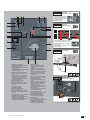
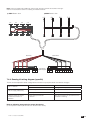
5. GENERAL OVERVIEW
5.1. Product introduction
2
3
4
1
7
9
19
17
14
13
12
1
11
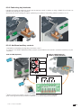
'7"9!"%(&"((/
F'K9"#%(4B)(5
B'/)(#y+.(#
'/9"#%F(4B)(5
'")""9:45I4$$5I::45
;'(#("#()"#))(&
='8(0
?'#
'>P3:97"
<'#2#(("
'&#()C3G(D
F'MP3:97#0!(%(2#(2K#(
B'7(/$(&40)B)(/$'I?5
'#)#.47:::)#!(%(&#)#5
'K(&$(/(((8)#M@:P7P/
;':)#.
9
7:::
M(%(
!($$$)
='($((
?'K.($((
'&#()$(4%((&#(5
EN
5.2. =>
2
3
4
7
9
9
11
1
12
14
13
'!"+(%(9
Electrical characteristics
Applicable standards and
(#"('
F')(y)#(#%*%/'
B'"4K5"F4%/5+(%(
'y)##$#%(%(
'((+(%(
;'@"/#"))"P3L
='$(#('4<;<5
?'&)#&)+'4y*yy)5
'#('4<;<5
<'3)"+#+'
'%(#%
F'&#()$
B'#)#+(%('
':)#+(%('
'>#y))'
EN
19
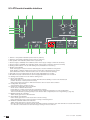
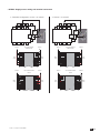
5.3. ?
4
7
9
ATyS t
5
1
0
3
60
2
5
10 1
0
20
10
20
60
1
READY
REMOTE CONTROL
AUT
PROG
OK
14
13
12
A: 3 Ph
B: 1 Ph
E:
F:
C: Neutral
D: Neutral
G: U 10% F 5%
H: U 20% F 10%
11
'"P3)(Green when in position I)
F'"FP3)(Green when in position II)
B'U)P3(Yellow when in position 0)
'##))(&:!(%(&P3(Green when supply I voltage is within the set limits)
'##))(&::!(%(&P3(Green when supply II voltage is within the set limits)
;'("($#"(! (Available as an accessory)
='M3P3
Green steady light : Product in AUTO, Watchdog OK, Product Available to changeover.
(Press PROG OK button in manual mode to save or revert to last saved settings).
?'K:P0M4K57#))(&1#%($<;<
'M0M@4M57#))(&1#%($<;<
<'("(F$#"(!'
'K0PP3'
(rotation incorrect / neutral position incorrect)
!
"#
F'+#)"
4 dip switches with 2 positions in each
B'7M>O9+#!)#%#'
ATTN: Active in Manual Mode ONLY
$%"%
&'
!*+%
!
%-135$""678'9
'@0PP3
Yellow steady light when in Manual Mode
'0P3
Green steady light when in Auto mode with no timers running.
!
!
"
;'M@MPP3'
Yellow steady light when in remote control mode.
""
!
;#!
"5<'!
"
5<="
5<>5<?!
5<=
EN
5.4. @
The ATy)#$(("!(-#9
5.4.1. &=
ø 1 mm
:7F$y8(#'
:7F$)"")("(##%(*
(&((#(('
:7<$%)""#(()('
5.4.2. B'
Temperature
KF<X<"#
KF<X=<"))(&O$
Kt: Correction Factor
Temperature
<'
<
<
<'?
<;<
<'=
;<=<
)(+9:#:.O$
)(#(&%$)+))('#(%-#)('
Hygrometry
?<#&"#
#&"#<
Altitude
0)F<<<(#"#
K(#O$%("))(&
Ka: Correction Factor
VWXV
VWXV
Ue
<'
<'?
:
<'?
<'?
5.4.3. '
Temperature
K<X=<
EN
21
Storage duration period
.##))$F
4M9%&*!()5
Storage position
XZ.#$B%.&%/!((&
[Z.#$%.&%/!((&
5.4.4. K
?y
Frame Size
Rating
F
B
;<
F<<
F
<
B
<<
<<
;B<
?<<
;
<<<
F
<
=
;<<
F<<<
?
F
<<
BF<<
22
EN
N° of
Poles
Reference
Number
#\-;]<^;
Net
Gross
"_`jV\kV
-/k$,k^-/;
B
B 3 012
;*?
<*
B;<.?<.B=<
B 4 012
?*<
*B
B;<.?<.B=<
B
B 3 016
;*?
<*
B;<.?<.B=<
B 4 016
?*<
*B
B;<.?<.B=<
B
B 3 020
;*?
<*
B;<.?<.B=<
B 4 020
?*<
*B
B;<.?<.B=<
B
B 3 025
=*=
*<
B;<.?<.B=<
B 4 025
?*
*?
B;<.?<.B=<
B
B 3 031
=*?
*
B;<.?<.B=<
B 4 031
?*
F*F
B;<.?<.B=<
B
B 3 040
=*?
*
B;<.?<.B=<
B 4 040
?*
F*F
B;<.?<.B=<
B
B 3 050
F*
*?
B;.B=?.F=
B 4 050
*
=*=
B;.B=?.F=
B
B 3 063
B*<
;*B
B;.B=?.F=
B 4 063
*
?*
B;.B=?.F=
B
B)8<8
F*<
*<
=B<.?<<.;<<
B:8<8
BB*B
*B
=B<.?<<.;<<
B
B 3 100
F*
*
=B<.?<<.;<<
B 4 100
B*<
<*<
=B<.?<<.;<<
B
B 3 120
B<*<
;*<
=B<.?<<.;<<
B 4 120
B*=
<*=
=B<.?<<.;<<
B
B 3 160
B*F
<*F
=B<.?<<.;<<
B 4 160
<*
;*
=B<.?<<.;<<
B
B 3 200
*?
;=*?
=B<.?<<.;<<
B 4 200
;F*=
=?*=
=B<.?<<.;<<
B
B 3 250
*?
;=*?
=B<.?<<.;<<
B 4 250
;F*=
=?*=
=B<.?<<.;<<
B
B 3 320
;F*
=?*
=B<.?<<.;<<
B 4 320
=;*
F*
=B<.?<<.;<<
5.4.5. '@;
The ATy)("#)!$9
()%(&'F<<2<?2
$3%F<<'
P"!(!'F<<;2
2F$3%F<<;'
5.4.6. Z?
The ATy)("#)!$MG'
5.4.7. WEEE
The ATy%#("F<<F2;2!9
*:<EMC standard
The ATy%#(":;<=
47#%((:#(*(2M(!$)
%("(((-#5'
Description
<6
\qj-=\V\/<k=-<\=-,
#
:7M
(
M
:7M
(
3
;<<<F
O645
3
;<<<F
?O645
Electromagnetic field
;<<<B
<6245
MK#
;<<<;
<645
#
;<<<
FO645)"
O645(
#
;<<<
FO645
Surge differential
;<<<
O645
EN
23
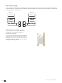
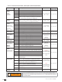
5.5. ATy''@B&@K&Z(Z@
(&\&]\(
B]&!@b=ZB'!&]\''@B&@
":Y::(('
P/$((#()%&$
M@:P7(/'7%(&$(/(()*$
C7(/B)D)'
@^&]Z_B%+,/*B7)89
:#)"
()'%#
rear position at the same time as the voltage sensing and
)"#(/%%'
@)%("##'
=ZB'!&]\&])=B&&B]
%#)%*$)'
(("(/$)B):*<::'
4K&+&5
TERMINAL SCREENS
CONTROL VOLTAGE TRANSFORMER
:#)"
()'
(("FB<6!%#))("
<<6'
DOOR ESCUTCHEON PLATE
^B%]&]\='@+,/*B7)89
&%+.%$
(()$##y)$"'
M!L(<"&$
backplate or frame
'=B`@%==Zb+'jx'9
REMOTE INTERFACES D10
(("FB<6&%#))(#
F2F6#.7"#))(&'!(%($#)
;<<
M3)(&9(("##))(&"
)%)(&(&'4P3)(&5
%==Z@^@]b%z&Z&b'B]'+'9
'B^^%]&'&B]'(Z@
&)((&#B"&$y'
7%/($):::9(
MR
#%(4B(5$#"3<
#.(&@2@#.(&)'
)(&2((#('
:(#$$F<<<BF<<'KP"
(!(9)(#('
!@bZB'!%B{^]%Z@Z@'B`&'_
The ATy("(!"&
('%)("/&(/'
3"(/&(/%(&#$('
M$'
<<='
24
EN
B
M$$##((
)#(#'
43"(%($"""''5
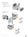
6. INSTALLATION
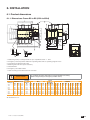
6.1. =
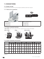
6.1.1. "()(*+,/*7)89
J
M
3
J1
U
4
119
223
101
=
Fix. 180
6
CA
140
V
120
=
Fix. 195
AA
BA
AC
270
CA
W
10.5
Y
48
Y
3
2
X
T
T
T
11
88
138
Z1
3
F
20
5
Z2
H
A
165
10
Ø7
50.5
CA
Fix. 180
Fix. 195
C
1
W
U
Ø9
=
'7(/K(&9P/%/$#)B)(/$'I?
F'&#()9.#)#")($F.<
B'
'#$$")&
'7
;'&!%((
='K(####$$
CAUTION
+9
F
;<
F<<
F
<
B
<<
<<
;B<
B
A 3p.
B<
B<
B<
B
B
B
B
B
A 4p.
BB
BB
BB
B
B
B
C
F
F
F
F
F
F
BF
BF
shrouds
AC
FBB
FBB
FBB
F??
F??
F??
<F
<F
To consider the space required for manual operation and wiring.
#$%'*+;'<>$%?>%@%Q<%'[?$\']^%"'_>%`
(
F 3p. F 4p.
F?;'
B=
F?;'
B=
F?;'
B=
BF? B=?
BF? B=?
BF? B=?
B== B=
B== B=
H J 3p. J 4p.
?
?
?
F F
F F
F F
FF F
B<
FF F
B<
J1
B
B
B
B
B
B
B
B
Switch
M 3p. M 4p.
F< <
F< <
F< <
;< F<
;< F<
;< F<
F< F=<
F< F=<
Connection
T
B;
B;
B;
<
<
<
;
;
U
F<
F<
F<
F
F
B
V
F
F
F
B<
B<
B
<
<
W X 3p. X 4p.
F?
FF
F?
FF
F?
FF
BB
BB
BB
BB
BB
BB
B F'
B='
B F'
B='
Y
B'
B'
B'
B'
B'
B'
Z1
B?
B?
B?
B'
B'
B'
B
B
Z1
B
B
B
BB'
BB'
BB'
<
<
AA
B
B
B
;<
;<
=<
F;<
F;<
(
B<
B<
<
FF<
FF<
CA
<
<
<
F<
F<
All dimensions in mm
EN
6.1.2. "(7}(~+<88,7889
J
3
M
4
51.5
&?B?.
12.5
T
T
166
166
T
X
2
3
12.5
6
280
200
250
=
B
AA
AC
=
169
V
250
U
Y
5
Y
3
Z1
F
48
94
253.5
1
293
391.5
;<<
33
8.5
50
28.5
15.75
60
15
25 25
30
30
45
45
90
214
20
12.5
15 28.5
15.75
!<=?%.
8.5
!<==.
10 33
5
ø 15
138
ø12.5
5
50.5
16 x 11
ø9
&?B.
F
<
!<?.
?<<<<<
=
'7(/K(&9P/%/$#)B)(/$'I?
F'&#()9.#)#")($F.<
B'
'#$$")&
'7
;'&!%((
='K(####$$
To consider the space required for manual operation and wiring.
#$%'*+;'<>$%?>%@%Q<%'[?$\']^%"'_>%`
CAUTION
+9
?<<
<<<
F
<
;<<
B
(
B=<
B=<
B=<
B?<
screens
AC
;
;
;
B
(
F 3p.
<
<
<
;
F 4p.
?
?
?
=;
J 3p.
B<=
B<=
B<=
B
J 4p.
B?=
B?=
B?=
M 3p.
F
F
F
B=
M 4p.
BB
BB
BB
;=
Connection
T
?<
?<
?<
F<
U
<
<
;<
<
V
;<'
;<'
;
X
='
='
='
B
Y
=
=
=
?
Z1
;;'
;;'
;;'
;='
AA
BF
BF
BB<
F??
All dimensions in mm
EN
6.1.3. "(<+/888)/889
A
51.5
569
330
380
250
&?B.
461
258
125
M
120
120
120
425
53.5
F<<<BF<<
138
ø12.5
5
214
50.5
!<?.
25 25
30
30
45
45
90
&?B.
15
12.5
5
20
?
'7(/K(&9P/%/$#)B)(/$'I?
F'&#()9.#)#")($F.<
B'
'#$$")&
'7
;'Emergency removable handle
='K?*43#($5$&$)"(
?'K(####$$
To consider the space required for manual operation and wiring.
#$%'*+;'<>$%?>%@%Q<%'[?$\']^%"'_>%`
CAUTION
+9
F<<<VBF<<
B
A 3p.
A 4p.
M 3p.
M 4p.
;
=;
B=
;=
All dimensions in mm
EN
27
6.2. ^
F
;B<
M
O
Not Allowed
/
?<<BF<<
M
Not Allowed
O
/
CAUTION
Always install the product on a flat and rigid surface.
6.3. ?
DANGER
Never handle any customer mounted accessories while there may be the risk of
voltage being or becoming present.
6.3.1. (
F
;B<
?<<;<<
&
?
EN
M-#9
.#-#9
;9*
@'
?9?*B@'
<9F<@'
F9<@'
;9
*@'
?9B@'
<9F;@'
F9
@'
6.3.2. !(%($F
;B<
KBK
9
Upstream, downstream, front or rear
#'
H
+"%%(&
the front terminal shrouds are to be
(('
6.3.3. 125A to 630A
500A to 1600A
2000A to 3200A
EN
29
6.3.4. ';+/888)/88"(<9
!
Conditions of use of these products may
lead to a derating.
18.81 (&$
23.54 ()$
13.6 (&$
18.38 (&$
"
17.18
x
SOCOMEC “Application guide”
2.02
x
"
4.72
4.72
4.72
2.10
x
4P
9.84
3P
I th = 2000 A
14.96
1
10.15
www.socomec.com
Ø 0.49
Ø 12,5
9.92
2
1.45 2.36
37
I th = 2500 A
3P
2.91
74
1.45
)
x
74
37 5.07
129
6.10
4P
) )
)
)
2.91
"++++)+
1.18 4.5 0.86
132
30 4.5 22
3
211
5.19
30 4.5
8.30
1.18 4.5
I th = 3200 A
3P
4P
"&+++
provided
fourni
6.41
163
226
8.89
1.18 4.5
30 4.5
%j,`6-V\/0-_/0-/(VV
?(
]
`?('
!
B(@%==Z&@(bB_@
Connection reference numbers and contents:
x1
+
included with 3200A
product as standard
2619 1200
x6
708 lb-in
80 Nm
2629 1200
2699 1200
"
x1
x6
708 lb-in
80 Nm
708 lb-in
80 Nm
x2
x1
+
x6
708 lb-in
80 Nm
2639 1200
x1
+
708 lb-in
80 Nm
+
x6
4109 0250
708 lb-in
80 Nm
x6
4109 0320
&
)
11
12
H M12-35
H M12-55
H M12-55
A H M12-35
( H M12-45
H M12-65
H M12-65
H M12-55
H M12-55
H M12-55
H M12-65
H M12-65
H M12-65
6.8 - {
6.8 - {
6.8 - {
6.8 - {
6.8 - {
6.8 - {
6.8 - {
6.8 - {
6.8 -{
6.8 - {
6.8 - {
6.8 - {
6.8 - {
Rondelle contact
MOY. M M12
NFE 25 511
H M12
{
{
{
{
{
{
{
{
{
{
{
{
{
{
{
{
+
+
{
{
{
{
{
{
{
{
]M$#%-#&!%!%("$))('
K$#((#()(&-#&%&#%$)(4B)(5#()(&%&F4@$"5
EN
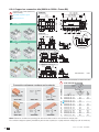
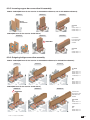
6.3.5. &;
/888/*88+^'?&/888),88*?&/*88:,88*9
"
"
"
Direct
Connection
"|"
O9
F;F<<.
F;FF<<.
F;BF<<.
)/88+^'),88,89
"
"
"
%F;F<<
included with
BF<<
! /88^
A
(
(
"|"
O9
F;FF<<.
F;BF<<.
A
6.3.6. B
/888/*88+^'?&/888),88*?&/*88:,88*9
"&
"
")
"&|"
O9
F;F<<.F
F;F<<.F
F;FF<<.
<<F
<.
")
O9
F;F<<.F
F;FF<<.F
F;BF<<.F
)/88+^'),88,89
"
! /88^
"
"
%F;F<<
included with
BF<<
"|"
O9
F;FF<<.
<<BF<.
"
O9
F;FF<<.F
F;BF<<.F
EN
31
6.3.7. Power supply
7"$$<<6*77!())()!!(%(&$
#(#'$9<<6IFB<69F<<6':y"((-#F$
%"%("'
400 Vac
400 Vac
101 102
Power 230 Vac
230 Vac
202 201
Source 2
Power 230 Vac
Source 1
230 Vac
7)<
!(%($F
;B<(&
KB*
(# F ) !L
(<"&$%$
enclosure or frame on which the device is
#'&(%#)(
(#)'
32
EN
6.3.9. =
;;
;
: $ (/ (( ( %/#) ( ) < # M@: P7 (/' */&(/<)'
)((&"(#)C)(/B)D/&(/"((%):*<::
125A to 630A
<88)/88
6.3.10. :$)%/($):::9
.#$F@2@(#.(&%+$)'4#%(&&%
-#'5
,/*7)8+B
9
<88,788+B
9
/888)/88+9
?F ? ?
7:
7::
F 4$5
Pos I
{
81
45
82
Pos II
84
91
92
94
81 82 84 91 92 94
45
H##.(&):::*#")!'
H#"#.(&):::*#(")!'
EN
33
7. CONNECTIONS
7.1. Power circuits
K)+"/)")%(*)($)B;'
7.1.1. Cable or bar connections
2A1 2A3 2A5 2A7
1A1 1A3 1A5 1A7
2A2 2A4 2A6 2A8
1A2 1A4 1A6 1A8
M-#9
.#-#9
;9*
@'
?9?*B@'
<9F<@'
F9<@'
;9
*@'
?9B@'
<9F;@'
F9
@'
7.1.2. =
125A to 630A - M$C7#D*)F
$)"(('
<88,888
1250A
1600A to 3200A
16 x 11
ø9
ø12.5
5
33
8.5
50
15.75
28.5
12.5
15.75
60
15
!<=?%.
8.5
15 28.5
ø 15
!<==.
10 33
5
25 25
30
30
45
45
90
7.1.3. Power connection cross-section
()
(:
(*
(7
(~
(<
125A 160A 200A 250A 315A 400A 500A 630A <88 1000A 1250A 1600A 2000A 2500A 3200A
#
cables section
#4F5*:
<
=<
F<
?
F<
#%
#
4F5*:
.#
cables section
#4F5
<
<
<
F<
F<
.#%
"#45
F
F
F
BF
BF
BF
F.
< F.?
F.F<
F.B<
.
F.<
.
F.
<
.
F.;<
.
F.?<
.
<
;B
;B
;B
F.<< B.<< .<< B.<<
.
.
.
.<
F.B<< F.B<< F.B<< .?
.?
;.?
<
<<
<<
<<
<<
@$((9/#%((2!()+)
'
34
EN
7.1.4. Standard Connection Priority Source Supply On Switch I
)#(!$$&"$(("+#9
<<;"":
F<F<;"::'
=+9
I
P
1
2
II
I
Source 1
Source 2
202
Voltage Sensing
Source II - 1Ph / 3Ph
0 - 332 / 575 (600Vac)
Power 208-277V~ +/-20%
201
Aux Supply-1
Power-230V
208-277 Vac ±20%
(166-332Vac)
Power 208-277V~ +/-20%
Aux Supply-2
Power-230V
208-277 Vac ±20%
(166-332Vac)
101
102
Voltage Sensing
Source I - 1Ph / 3Ph
0 - 332 / 575 (600Vac)
L1 - 203
L1 - 203
N - 103
N - 103
L2 - 204
L2 - 204
L3 - 104
L3 - 104
L3 - 205
L3 - 205
L2 - 105
L2 - 105
N - 206
N - 206
L1 - 106
L1 - 106
CAUTION
It is recommended to connect power and sensing with the ATyS voltage sensing
and power supply kit available as an accessory.
In this case ensure to mount the kit before connecting the power cables.
EN
7.2. Networks and Power Connection possibilities
7.2.1. ?;
,(Z -/;`\8],0\/\<}_=^
Source 1
Source 2
1
1
N
N
Load
/(Z }_8],0\/\<}_=^without neutral
/](Z }_8],0\/\<}_=^}-<]/\j<=,`
Source 1
Source 2
Source 1
Source 2
2
2
1
1
N
N
2
2
3
3
Load
Load
)(Z ]=\\8],0\/\<}_=^without neutral
4"75
)](Z ]=\\8],0\/\<}_=^without neutral
Source 1
Source 2
Source 1
Source 2
1
1
1
1
2
2
2
2
3
3
3
3
Load
Load
:(Z ]=\\8],0\/\<}_=^}-<]/\j<=,`
4"75
Source 1
1
:](Z ]=\\8],0\/\<}_=^}-<]/\j<=,`
Source 2
1
Source 1
1
2
2
2
2
3
3
3
3
N
N
N
N
Load
Load
:,](Z Source Z]=\\8],0\/\<}_=^}-<]/\j<=,`
Source F Z-/;`\8],0\/\<}_=^}-<]/\j<=,`
Source 1
Source 2
1
2
1
3
N
N
:/](Z Source Z]=\\8],0\/\<}_=^}-<]/\j<=,`
Source F Z-/;`\8],0\/\<}_=^}-<]/\j<=,`
Source 1
Source 2
1
1
2
1
3
1
N
N
Load
@9(&()('
EN
Source 2
1
Load
@9(&()('
7.2.2. ^
7#
type
&)
&
&
Network type
!
Source Source F
)
F"
&)
&
&
&)
&
&)
&)
&)
&)
&
&
!
!
!
!
!
!
F)
F"
F)
B"
B)
B"
B)
B"
B)
"
B)
"
2
1
1
1
1
1
&)
!
B)
"
)
F"
1
!
B)
"
B.)
"
1
1
N
Source N
3
3
2
2
1
1
3
2
3
2
1
1
N
2
N
3
1
2
N
3
1
2
N
3
1
1
N
N
2
N
Source F
N
3
3
1
S1
S2
R1
R2
3
Voltage sensing
Source 6
Source F 6
Source
presence
4#
!(%(5
Source
in ranges
40*6*K5
M
phase
order
Neutral
position
Voltage
unbalanced
is lower
than
threshold
R2
R1
N
S2
S1
N
0F
6*6F
0F
6*6F
0FB
R2
R1
T1
T2
N
2
2
3
S1 S2
2 3
N
3
1
N
2
1
R1
R2
T1
3
3
0FB
3
2
1
1
R1
R2
1
3
2
2
2
&)
cabling
4(5
&)
&
&
23
0F*0FB*0B 0F*0FB*0B 0F*0FB*0B
6*6F*6B
0F*0FB*0B 0F*0FB*0B 0F*0FB*0B
6*6F*6B
1
R1
R2
S2
T2
N
S1
T1
23
1
R1
R2
S2
T2
N
S1
T1
23
R1
R2
S2
T2
N
2
0F*0FB*0B
6*6F*6B
0F*0FB*0B
6*6F*6B
0F*0FB*0B
6*6F*6B
6
0F*0FB*0B
6*6F*6B
6*6F*6B
(&
(&
(&
(&
(&
(&
S1
EN
37
7.3. Control circuits
7.3.1. Typical ATy
.)(9("$<<6))(!B)#(#))(&'
1
2
17
N
L1
64B 63B 417 416 415 414 413
N
11
10
6
312 313 314 315 316 317
15
14
13
12
RJ
L3
16
L2
L3
L2
203 204 205 206
16
106 105 104 103
17
102 101
F1 type gG
201 202
\]*^_`&
Sensing and
Power supply Kit
(excludes the need
for fuses F1 & F2
Fus. 4A
F2
L1
Fus. 4A
type gG
7 8 9
63A 64A 24 14 04 13
3<
M
3)(&0
5 4 3 2 1
1 preferred source
2 alternate source
'7<
F'7:
B'7::
'U))&
'M(%(47&!#5
EN
;'7#!(%(#)#45
='7::#.
?'7:#.
'7<#.
<'273<)(&
'7#!(%(#)#45
F':27:%$(
B':27#($4M5
':27$#)&9#)&
F$(*$)
':27"2"##)&9#
priority when closed
;'6()#
='7"#))(&:)#
CAUTION
Verify that the Auxiliary power supply feeding terminals 101 and 102 / (201 and
202) are within the limits of 208VAC -> 277VAC ±20%
DANGER
Do not handle any control or power cables connected to the ATyS when voltage
may be present.
7.3.2. ATy
7.3.2.1. Motorisation module wiring
All pressure on the connector
pins is to be avoided during
"$#.(&%(
(%(9
!KK9
"7:::279
"7::279
"7<:279
9
7!(
7!(279
7::#.9
7:#.9
7<#.9
9
BF
BB
B
B
B;
B=
;B
;
F
<
B
CAUTION
The RJ45 terminal is
not a LAN connection
63B
64B
RJ45
Common
ATS Module
Control Inputs (Fixed)
413
414
415
416
417
L1-106
L1-106
L3-104
L3-104 Voltage Sensing
Source 1 - 1Ph/3Ph
L2-105 7::<==79;
L2-105
N-103
N-103
7899::;
417 416 415 414 413
102
}
64B 63B
101
Product available
To D20
Aux Supply-1
Power 230V
7.3.2.2. ATS control module wiring
Power 208-277V~ +/-20%
ATyS t
5
1
0
5
10 1
0
20
60
10
20
60
READY
REMOTE CONTROL
AUT
PROG
OK
A: 3 Ph
B: 1 Ph
E:
F:
C: Neutral
D: Neutral
G: U 10% F 5%
H: U 20% F 10%
N-206
N-206
L2-204
Voltage Sensing L2-204
Source 2 - 1Ph/3Ph
7::<==79; L3-205
L3-205
L1-203
L1-203
202
7899::;
Aux Supply-2
Power 230V
201
Power 208-277V~ +/-20%
EN
39
7.3.2.3. Terminal denomination, description and characteristics.
Description
Motorisation
Module
<
#.7<@((&)
B
$#.):<::
Output
Contacts
#.):9@((&)
F
#.)::9@((&)
;B
#(!(%(#)#'("
ATy#)('
(No Fault powered and ready to changeover)
;
ATS Output
Contact
;B
;
(#(!(%(#)#'("
&#)('(No Fault,
!
*9
Contact
?
$#.):
?F
#.):9@((&(
?
Included with
'@@@5'@@ #.):9@((&)
$#.)::
Optional for
3@@<?@@
F
#.)::9@((&(
#.)::9@((&)
ATS Power
supply Input I
<
7"#))(&:IP
<F
7"#))(&:I@
K
&
<B@
:@#(!()#
<PB
:I7B!()#
Source
&
<
PF
:7F!()#
<;P
:7!()#
ATS Power
supply Input II
F<
7"#))(&::IP
F<F
7"#))(&::I@
K
&
F<BP
::7!()#
F<PF
::7F!()#
Source
&&
F<
PB
::I7B!()#
F<;@
::@#(!()#
Motorisation
Module
BF
M(%("("B=
BB
7<$("B='47&)#
$)#(<)5
B
7::$("B=
B
7:$("B=
B;
7<$("B=
B=
(($BFB;&4)+
6(#))(&5
B
:)#:97M:!##))(&)&"(
"='4#)&"/"(5
:)#:F9)&##))(&:::'49
:")::"("=
:)#:B9MI#($"(
"='4)!($5
;
:)#:9:%$(#"
("=
=
#))(&$)#4B;5
MR
#)#3<)(&#(
Control Inputs
ATS Module
Control Inputs
&?
Characteristics Cable Section
3&F
2F
<6
'
IF'
F
3&
F2F
<6
'
IF'
F
3&
F2F
<6
'
IF'
F
F<?F==6
F<9
<2;<G8
'
IF'
F
;<<6
4))5.
'
IF'
F
BBF6
4)5.
F<?F==6
F<9
<2;<G8
'
IF'
F
;<<6
4))5.
'
IF'
F
BBF6
4)5.
9
3
&7"#))(&
'
IF'
F
.%((
<<
3
&)"#))(&'
9
To be used with
dry contacts fed
$=@P'
0)B
'
IF'
F
MR
K(*)($)B='
CAUTION
EN
Do not connect terminals 312 to 317, 413 to 417 to any power supply. These
order inputs are powered through terminal 317 (or 417 respectively) and external
dry contacts ONLY.
7.4. K
;
The ATy!(/!(%(&)(&$)"
":"::("#)$#'/")
%((#((#($(&((#))'
"()j(*j,/*j7)8
"(7j(<j<88j)/88
##/)#%$)"%('
CAUTION
$#(#/##)"%(
4%($#((&5'
7.4.1. >
)"#))(&/&%"$(("+#)%(9
B)"/"B"
P
230 V
@#(#($4"5
400 V
*#(%$(("9
1
Top or bottom cables entry
2
##))(&:":'
##))(&::"::
: # ) $ #(
#)"#(%"$(("9
N
K#(9PZPFZPBZ@
K#(($9@ZPBZPFZP
Source 1
Source 2
CAUTION
7&"")"%(4M)/(5
B"/4"##(5(#$)"#))(&('
4<<FF<IF<F5
#&#!$)(('
4M$&$(5'
EN
41
7.4.2. ;
+:>9
P
CAUTION
Ensure to mount the kit onto the product before
)"%('
$#(#/
mounting and during power cables connections
4%($#((&5'
Sources
7)8!"
<88!"
Specific strips to
$.%(&
%(&)
on the specific supports K@)(#
7.4.3. ;+9
?
")#
(/H":
MH"::
`
Wire numbering has been determined in accordance to
the power switch terminals
?'?
):"#
(/H"::
MH":
@
(/"#%F("&
(F$":::
1
1
3
5
3
5
7
7
II
I
2
2
42
EN
4
6
4
6
8
8
])+/!(%($&"#(($#('
M$$$('
7)8!"
<88!"
1-2
3-4
5-6
7-8
1-2
3-4
5-6
7-8
1-2
3-4
5-6
7-8
1-2
3-4
5-6
7-8
Red wires
7-8
5-6
3-4
Black wires
1-2
7-8
B
206
205
204
203
A
202201
B
mechanical
cables support
5-6
3-4
1-2
A
101 102
103
104
105
106
7.4.4. ;+>9
/%)+#"!&-#'
79@"/
7F9#))(&%(&
7B97&#))(&"
"#%4:5L
'
FB<2<<2?<6@"/
No Action
F=2FB<2F==6@"/
Y")
&
7/
Top Entry
7/)
7&#))(&
":
7(#
((#%'
??
?
45@-#$)#(($/$$&'
EN
43
x@=,];
7")#4(<<FYF<F<F5FF<2F<2F==64F<?F==65F<':&)
)" )# %( "/ +#' 47" #))(& % / %"
))%")#(5'
CAUTION
Verify that the power supply between terminals 101 – 102 and 201 – 202 (nominal
auxiliary voltage supply) is within 208-277VAC ± 20%.
/9
O+9
@"/B?<2
6F<"#(
#4/+-#59
K"/FF<2F<6F<*)"#))(&
%(%")
Red wires
B
206
205
204
203
A
202201
mechanical B A
cables
101 102
support
Black wires
Red wires
Black wires
B
103
104
105
106
206
205
204
203
A
202201
mechanical B A
cables
support
101 102
103
104
105
106
x@=/+
9
/(!$$&$#%&4%%)5'
#4%(5&
)#4%(5&
P
Sources
Sources
P
(/"":
(/""::
M""::
M"":
CAUTION
44
EN
Verify kit orientation before mounting the kit.
Kit output cables always on the right hand side (control module side).
x@=)
+#9#":
#"::
II
II
I
206
201 202
1 Power 230 V~
204
203
205
N
L3
L2
Voltage sensing
L1
103
102 101
1 Power 230 V~
Black
wires
105
106
104
N
L3
Voltage sensing
201 202
206
205
N
204
Voltage sensing
206
L3
205
L2
N
103
204
L3
104
Voltage sensing
L2
105
203
L1
N
203
Red
wires
Red
wires
Switch II
L2
102 101
N
105
104
L3
L2
106
Voltage sensing
L1
1 Power 230 V~
2
L1
L3
Power 230 V~
106
Red
wires
Switch II
TOP: SOURCE CABLE
ENTRY
Switch I
201 202
2
L2
N
103
Power 230 V~
102 101
Voltage sensing
Voltage sensing
L3
104
N
206
Switch I
L2
105
L3
205
Voltage sensing
L2
204
L1
Black
wires
L1
L1
Black
wires
106
103
2
1 Power 230 V~
Power 230 V~
2
203
BOTTOM: SOURCE
CABLE ENTRY
Switch I
102 101
Power 230 V~
201 202
TOP: SOURCE CABLE
ENTRY
Switch II
Black
wires
Switch I
L1
BOTTOM: SOURCE
CABLE ENTRY
Switch II
Red
wires
I
EN
<ATyB=@&]\^B@
The ATy (# B $ ) # ( " ( $ $ )#'y(!"(""!/&(/&)("!(%(
)'4%)+%&$CIOD$$5'
$)$(("9
#9
CM(&)$"D
#(9
CP(&#()D
P/9
C#(/)(/$(&D
AUTO MODE:
Activates the remote control
inputs and the ATS controller
#'
:%)(/$(&
:%$
manual operation handle
"0
3
0)%
when padlocked or when the
handle for manual operation is
inserted into the ATy'
90°
0
MANUAL MODE:
_<$,6`_k^\6
90
°
I
AUT
II
3
:%()#'
Allows to insert the handle
for emergency manual
)'
((")(/
7'(With the handle for
manual operation removed)
Turning the selector switch to
from AUT and back to AUT
$#('
MANUAL MODE:
$,6`_k^\6
:%()#'
:%$
&('
((")(/"
7'
POS 0
3
38xmm
Ø 4-
WARNING
EN
7(/ ) : :: )%( " )(
function is included in the ATy'
4M$)#(#5
3)$&#&"
)("0'()'
<,Manual operation
<,,@
The ATy%#((&)C#($"-#)ID"(((
)$$)""$#'$###((&#$
#'
To operate the ATy#((&#(!)%(*#$("#(
) 4 ) ?5 ( 4 ) ?5 & ( $ ( (
)!4)5'
#(<(/"(/"4))%5$#!
)'::::'
CAUTION
Ensure to verify the product position and
direction of rotation before effecting manual
)'
Ensure to remove the handle from the product
before changing the selector switch back to AUT
)'
<,/=
;
The ATy%)(/<)"()(/):*::!(%(
$&+)'
To padlock the ATy+#y("#(#&
#()((('4M!$5'
7#(()(/#"!(($#)B.'?)(/'
7(/!"))!-#(&)(/$#.#$?'
.#$B.?)(/&%)(/y)(/'
3xmm
Ø 4-8
CAUTION
As standard, padlocking is only made possible in the “O position”, when in
manual mode and with the emergency handle not inserted.
</Electrical operation
</,Dual power supply
The ATy(##()"#))(&%)"%"(<<FF<IF<F4F$$
#))(Y(!5"($9F.F<?IF==6F<24;;IBBF652
<2;<G8<'
EN
47
201
202
Power 208-277V~ +/-20%
Aux Supply-2
Power-230V
208-277 Vac ±20%
(166-332Vac)
Power 208-277V~ +/-20%
#:)#9<<4%&52
.4"5
#7969'?O6I'F2
<:;<<
(9#'
2.#F'
101
Aux Supply-1
Power-230V
208-277 Vac ±20%
(166-332Vac)
102
<//K
&(##(())!(4(<B<;F<BF<;5
74P@5#))($#)BBF6B)4PP5$#)
=
2;<<6'
& ( ( )* ) " #( "(( ) "# #(
"/' )(& + +# $ ( ) " "# #( # )
"4)2*235$$(('
Sensing connections are usually tapped directly off the ATy)"(#yS sensing kit available
&'/!(%("#(($#("/
+#"y"((%)'M$y&$('
!(##"((!#!(%(&$(!
supplies as well as the ATy#'
)#$(("9
$],0\=_<,<-_/(-V,`,/k\8],0\/\<}_=^0
7%(y(!(!(+#"#$"
&)>2G4<2F<5")"'
Frequency within set limits
"(()($-#&+###$"&)
>2G4
2<5")"'
Loss of Neutral
H#)X#())(4+#")"))"
F)*($#("((%$#%(('3"((%"
('
Loss of the main or alternative supply'
P$#))(&)(!($-#&+###$"
&)>2G4<2F<$0
2<$K5")"'#))(&"((%
$($$(#4#)K((5()'
K1#%($<I;<'
\<j=/_V,-/,/6(_=,`<\=/,<-\0j88`5
M#$#))(&)(!($-#&+###$"
&)>2G4<2F<$0
2<$K5")"'#))(&"((%
#$#4#)M((5()'
M1#%($<I;<#'
##&9K-#&9<'6(9
Voltage Sensing
Source II
1Ph / 3Ph
(0 - 332 / 575
(600Vac)
EN
L - 203
L1
LL1 - 203
N - 103
N - 103
LL2 - 204
LL2 - 204
L3 - 104
L3 - 104
LL3 - 205
LL3 - 205
L2 - 105
L2 - 105
N - 206
N - 206
L1 - 106
L1 - 106
Voltage Sensing
Source I
1Ph / 3Ph
(0 - 332 / 575
(600Vac)
</)"
Description
&(#$
$$)##;)((
#('@()"#))(&#(%#
)#0%#"#))(&/$
(B='
The &((#()#(#('
no additional power supply should be used on these contacts as the inputs
0%#"#))(&/$(='(
of the &#.)"#))(4<I<FF<F<F5#%!(%(
!)#BFB=B='
7#(#$!$)#9;<'
=
),/M(%("("B='
#%("B=!((()#.)$BB/)&
!($$)#BF'%((#BF!
()#"(%#(#'
=
),)7<$("B="0'4K"KK75
C7&:)#D"("B=/)&!((((
'&"((<)(BBIB=('
)&&!"')$
)#(%("#BFB=':)#(#!"
)#$;<')#"((%#!(%('
=
),:7::$("B='
!"&0"BFIB=(BBIB=)'
:)#(#!")::#$;<'
=
),*7:$("B=
!"&0"BFIB=(BBIB=)'
:)#(#!"):#$;<'
=
),77<$("B=
!"&0"BFIB=(BBIB=)'
:)#(#!")#$;<'K(
%"(B;B='
=
),~
#))(&$)#BFB;
=
:,):)#:*H2H#7&
7M:!2!##))(&)&"()"='H)
&"((%&$#(()")&'H("=&"((
)"#)&')&%&$#(:"!&%::%&#%&(
='
=
:,::)#:F*7&##))(&
)##)&##))(&:::'&$#("
=))&#))(&:'H("=)&::'
9)#!"BI=)'
Pin 4159:)#:B*#(M$
MI#($%C")&D+#"("='(("
($%/)&#))(&)+4(-#5')##$#(
"#C")&D$#'
=
:,7:)#:*:%
)#%#"("="#!&)
'H%!*&&%)#(4"(5
("BFIB=('
=
:,~
#))(&$+.)#I(B;'
EN
49
Technical data
:)#J&
3#:
P
P(
7#(#
7"):)#
#)6
3"!(425
:#(45
Motorisation Module
<'B
<'
/
<<4'"'
;H>5
;<
<'<;6
'?/64'F2
<#5
F2/6
'?/6
4":27(()5
Terminal connector
'
#2F'
.
ATS Control Module
;
F'
/
<<4'"'
;H>5
;<
<'<B6
F'/64'F2
<#5
F2/6
'?/6
4":27((
)5
'
#2F'
.
Remote control logic
M")%!0%&.(!($%%!#
)#BFB='
3)"+#"&)$(&%))(y'
:)#((
('
:(*y)#!)&:::!<$(%)(
%&)(&%(B;B='
&
Impulse logic
The ATy!%()4:II::5$ order I
!)#('
order 0
"$(;<
&")'
order II
:::!)&!<'
position I
position 0
position II
;?@[
@9(.(#$'
4@9.(#)"(&5
'Z
Contactor logic
The ATy!)+)4:::5$ order I
('
'4B;IB=5
:::!)&!<'
:::!-#()&'
-<
maintained).
:$:::))*!#
8)' (With the power supply available).
EN
order 0
order II
position I
position 0
position II
maintened
4@9.(#)"(&5
</:"j
Description
As standard, the ATy -#)) " $# +. #)# ( #('
43&%)"%'
$_0-<-_/,j{-`-,=5k_/<,k<
The ATy-#))")4:II::5#.(&#)##B$$"'
=,)8:,:/:
4@((&)")B5
5<$=_6jk<,,-`,`\_j<8j<V_<_=-0,<-_/
Pin 63A – 64A
4@((&)(("!(%(5'
! $%/ %# )#L !(%(& L )& $ $ #))(&(!'$%/!(!#(.(#((
&%)(&'
The ATy)$($#(#)*")#$#(#
!&
#'#y)($()#'#($
$(*)$+'
Should the ATy#(%#!(%(*;BI;)*)"2&P3L
"$$*$#(P3!'$#(P3"((!$(#$+)"
!(%($#('$#(")#"$0#(
#'
ATy457#!(%(20!(%(H(&"(()$&$$(("%("9
K#&*C7#!(%(&D$!(&%)'
=%
`Z@'
7##(
4#5
(!(#$
)$$#(!4@$)25
7"$(!
#)##$(
:!()##
Abnormal switching when not in manual mode
M-#)
P/!"#(
.(K#(0)#
0.)#"#"(
Inhibition
Yes
No
Yes
Yes
Yes
No
No
Yes
Yes
Yes
No
Yes
"
<@"
B""8"
=7)(7:(
&7#!(%(#)#4#(5
4@((&)(("!(%(5
64B 63B
The above contacts may be used separately for precise monitoring of the state
of each module or wired in series to monitor the availability of the ATS and
#()(#'
EN
Technical data
#.(&J#&
+#
(#
M)
Startup duration
M6(2"6(
M#
#)69
3"!(4259
3(2)9
:#(9
#)#(9
@
<</&(
I<
F<<
F
<6
F
'?/64'F2
<#5
F2/6
'?/64M$:#(5
'?O6
'
F#2F'
F.#
<)=
The ATy%)$"!+#$$(('
ATyS t
5
1
0
5
10 1
0
20
60
10
20
60
READY
REMOTE CONTROL
AUT
PROG
OK
A: 3 Ph
B: 1 Ph
E:
F:
C: Neutral
D: Neutral
G: U 10% F 5%
H: U 20% F 10%
C+
7#
&)9
] #&C#(D"#.(&"/#))(!(%('
# @=, SET3)")$CGD-#'
43)"$+#5'Note: The
READY LED will Flash'
# @=/ SET the potentiometers paying attention to the arrow
indication
4F7"%()'K*M9K(#
2M#5
# @=) READ the network voltage and frequency'
477M>O%#$F
"/!(#5
$""8
# @=: SAVE((+#!(#'47*
3)"#$'
477M>O%#(&!9
;<5H
BJQSBJ!
-VCC9
# @=*)##!"&0
$7'
H
BJQSBJ
light.
EN
9$&#M3P3"(("&$"(($$
!'#&M3P3!!!(#"#(
!)(&!(#%&)7M>O%#%&'
4!#((+#%#&!"
!(#)#5
"
&&%-#))"(%(!
(+#'
M$)#&$('
<),,
#)##(3)"#(("!'7%(!
!& $ ) C GD % %( %("' K !* ) $# (
%$$((1)"'
]M3P3"((#("!%!
%&)7M>O%#(&'
READY
R
OTE CONTRO
PROG
OK
A:
B:
C:
D:
Dip Switch Setting Options
3)"
2
3)"F
23
A 7@"/
(7@"/
493)"F!)5
7"@"/4:(#@#(5
4(("($#($#%((5
3 7B"@"/4H#@#(5
3)"B
2K
E H#(&U743 <5
3)"
>2G
> (3(09<23(K9
F
45
U)(&F43 F5
G (3(09F<23(K9<
45
F(&U)))(%(":2::!(%('
H$$($#*F#(&#"$($#'
<)//
#)##(F)#(("!)&
")'($)$")+
%%(%("'
Note9M3P3"((#("!%!
%&)7M>O%#(&'
EN
5
1
0
5
10 1
0
20
60
10
20
60
Functional Description
7
FT
#))(&#K(#9<;<
7F
M
#))(&#M#9<;<
Position Setting Identification
7'@
F
B
;
=
?
<
F
B
K45
<
F
B
?
<
F<
B<
<
<
;<
M45
<
F
B
?
<
F<
B<
<
<
;<
<)))>
&(#C#+#$#!(*)*#()
$-#&(!(#!(('
$+#(!(##)#))(&"*!+&$'
:)!"/#))(&4F<?IF==6F<5!(%("&!(
(<BI<;%':)$%(#&/&%)!
&'
READY
R
A:
B:
REMOTE CONTROL
AUT
PROG
OK
C:
D:
#)##('
7
(MC7M>OD%#$F##))(&!(*$-#&*)
#()'
]M3P3"((4$$5##(!
%!%&)7M>O%#(&'4M$75'
<)::>
6+#)7M>O%#(&9;<'
]M3P3$$!(#!(('
READY
A:
B:
REMOTE CONTROL
AUT
PROG
OK
C:
D:
<)**=
$$((")*&)#&0)#("
EN
#'
]H)#)"))(&+#*$")#$#(#
7HMM3(#(%&>('
5
1
0
5
10 1
0
10
20
60
20
60
READY
REMOTE CONTROL
AUT
PROG
OK
A: 3 Ph
B: 1 Ph
E:
F:
C: Neutral
D: Neutral
G: U 10% F 5%
H: U 20% F 10%
5
1
0
5
10 1
0
20
60
10
20
60
READY
REMOTE CONTROL
AUT
WARNING
PROG
OK
A: 3 Ph
B: 1 Ph
E:
F:
C: Neutral
D: Neutral
G: U 10% F 5%
H: U 20% F 10%
3)$&#&"
)("0'()'
9. CHARACTERISTICS
EN
:;<=B:;<=;
F
;B<2B
&th at 40°C
K8
M#(!(0i4654)"#5
M)#("!(0imp4/654)"#5
M#(!(0i4654)#5
M)#("!(0imp4/654)#5
125 A
160 A
200 A
250 A
315 A
400 A
500 A
630 A
B
?<<
?
B<<
B
?<<
?
B<<
B
?<<
?
B<<
<<<
F
B<<
<<<
F
B<<
<<<
F
B<<
<<<
F
B<<
<<<
F
B<<
{(+,9
F
{(+,9
;<
{(+,9
F<<
{(+,9
F
<
F<<
F<<
{(+,9
B
B
F<<
{(+,9
<<
<<
F<<
{(+,9
<<
<<
<<
{(+,9
;B<
<<
<<
{(+,9
F
2F
F
2F
F
2F
F
2F
F
2F
F
2F
F
2F
?<2?<
F
2F
F
2F
F
2F
;B2?<
F
2F
F
2F
F
2F
F
2F
F
2F
F
2F
F
2F
F
2F
{(+,9
;<2;<
;<2;<
;<2;<
;<2;<
;<2;<
;<2;<
;<2;<
?<2?<
;<2;<
;<2;<
F
2F
;B2?<
;<2;<
;<2;<
;<2;<
F
2F
;<2;<
F
2F
F
2F
F
2F
{(+,9
F<<2F<<
F<<2F<<
F<<2F<<
F<<2F<<
F<<2F<<
F<<2F<<
F<<2F<<
?<2?<
F<<2F<<
F<<2F<<
F
2F
;B2?<
F<<2F<<
F<<2F<<
F<<2F<<
F
2F
F<<2F<<
F
2F
F
2F
F
2F
{(+,9
F
<2F
<
F
<2F
<
F
<2F
<
F<<2F<<
F
<2F
<
F
<2F
<
F<<2F
<
F<<2F<<
F
<2F
<
F<<2F<<
;<2;<
F
2F
F
<2F
<
F
<2F
<
F
<2F
<
F<<2F<<
F
<2F
<
F<<2F<<
F<<2F<<
F<<2F<<
{(+,9
B
2B
B
2B
B
2B
B
2B
B
2B
B
2B
F<<2B
F<<2F<<
B
2B
F<<2F<<
;<2;<
F
2F
B
2B
F
<2F
<
F
<2F
<
F<<2F<<
B
2B
F<<2F<<
F<<2F<<
F<<2F<<
{(+,9
<<2<<
<<2<<
<<2<<
<<2<<
<<2<<
<<2<<
F<<2<<
F<<2F<<
<<2<<
F<<2F<<
;<2;<
F
2F
<<2<<
F
<2F
<
F
<2F
<
F<<2F<<
<<2<<
F<<2F<<
F<<2F<<
F<<2F<<
{(+,9
<<2
<<
<<2
<<
<<2
<<
<<2
<<
<<2
<<
<<2
<<
<<2
<<
<<2<<
<<2
<<
<<2
<<
<<2<<
<<2<<
<<2
<<
<<2
<<
<<2
<<
<<2
<<
<<2
<<
<<2
<<
<<2
<<
<<2
<<
{(+,9
;B<2;B<
;B<2;B<
;B<2;B<
;B<2;B<
;B<2;B<
;B<2;B<
<<2
<<
<<2<<
;B<2;B<
<<2
<<
<<2<<
<<2<<
;B<2;B<
;B<2;B<
;B<2;B<
;B<2;B<
;B<2;B<
;B<2;B<
;B<2;B<
;B<2;B<
<<4B5
;<
<4B5
F<<
<
F
<
<
B
<
<<
<
<<
<
;B<
Rated operational currents Ie (A) according to IEC 60947-6-1
6
6
6
%
B
BF
BB
Rated operational currents Ie (A) according to IEC 60947-3
6
6
6
6
<<6
<<6
<<6
<<6
;<6
;<6
;<6
;<6
FF<634F5
FF<634F5
FF<634F5
FF<634F5
<634F5
<634F5
<634F5
<634F5
%
F<2F<
F2F
FF2FF
FB2FB
F<2F<
F2F
FF2FF
FB2FB
F<2F<
F2F
FF2FF
FB2FB
3F<23F<
3F23F
3FF23FF
3FB23FB
3F<23F<
3F23F
3FF23FF
3FB23FB
Fuse protected short-circuit withstand as per IEC 60947-3 at 690 VAC
<<4B5
F
7)!##4/5
$#45
Circuit breaker protected short-circuit withstand with any circuit breaker that ensures tripping in less than 0.3s(4)
F4B5
M"#<'B:cw4/5
F4B5
F4B5
=
=
<4
5
<4
5
<4
5
<
F';
Rated short-circuit withstand without protection
M"#;<:cw4/5):;<=;
6
M"#:cw4/5):;<=B
;<6
M)/"#4/)/5):;<=B;<6
4B5
4B5
4B5
=
=
=
?
?
?
<
<
F<
F<
F<
B<
B<
B<
B
<
=<
<
?
F<
<
F
2B
F
2B
F<
F
2B
<
BF
F<2F;
F<
BF
F<2F;
F<
BF
F<2F;
F.?
<
F<2F;
F.
<
F.B<.
F.B<<
<
F<2F;
<'=
<'
<'B
<'=
<'
<'B
<'=
<'
<'B
'B
<'?
<';
'B
<'?
<';
'B
<'?
<';
'B
<'?
<';
'B
<'?
<';
;;2BBF
;;2BBF
;;2BBF
;;2BBF
;;2BBF
;;2BBF
;;2BBF
;;2BBF
?2F
F<;2
?2F
F<;2
?2F
F<;2
F=;2
F?2B=
F=;2
F?2B=
F=;2
F?2B=
F=;2
<
F?2=F
F=;2
<
F?2=F
<<<<
'=2;'
;'B2='
;'?2?'<
<<<<
'=2;'
;'B2='
;'?2?'<
<<<<
'=2;'
;'B2='
;'?2?'<
?<<<
;';2='
='F2?'<
='=2?'
?<<<
;'=2='?
='B2?'
='?2?'
?<<<
<<<
<<<
;'=2='? '2B'B '2'<
='B2?' F'<2B' F'
2';
='?2?' F'
2' B'<2
'
Connection
.##%(45
##%#%45
.##%(45
.##%#%"45
-#2.4@5
Switching time (Standard setting)
::::::45
:<<::45
3#$¢((%(/#¢:::45
Power supply
2.465
Control supply power demand
7"#))(&FB<6#2(465&
7"#))(&FB<6#2(465&***)
Mechanical characteristics
3#%(&4#%$)&(5
H&B274/5
H&B274/5
H&***)B274/5
-<9+!
X*Z+!
[X*
-'95Z!
'
\]\<
\Z\>Z!
'
EN
-59><8^+
-?9^!
Z
@5
C!
Z7
Z$
-895@"
?<<BF<<2;?
&th at 40°C
<88
1000 A
1250 A
1600 A
2000 A
2500 A
3200 A
K8
M#(!(0i4654)"#5
M)#("!(0imp4/654)"#5
M#(!(0i4654)#5
M)#("!(0imp4/654)#5
;
<<<
F
B<<
;
<<<
F
B<<
;
<<<
F
B<<
=
<<<
F
B<<
?
<<<
F
B<<
?
<<<
F
B<<
?
<<<
F
B<<
{(+,9
?<<
?<<
?<<
{(+,9
<<<
<<<
?<<
{(+,9
F
<
F
<
?<<
{(+,9
;<<
;<<
<<<
{(+,9
F<<<
F<<<
F
<
{(+,9
F
<<
F<<<
F
<
{(+,9
BF<<
F<<<
F
<
{(+,9
?<<2?<<
?<<2?<<
?<<2?<<
?<<2?<<
?<<2?<<
?<<2?<<
;B<2;B<
<<2<<
?<<2?<<
?<<2?<<
;B<2;B<
<<2<<
?<<2?<<
?<<2?<<
?<<2?<<
?<<2?<<
?<<2?<<
?<<2?<<
?<<2?<<
?<<2?<<
{(+,9
<<<2<<<
<<<2<<<
<<<2<<<
<<<2<<<
<<<2<<<
<<<2<<<
?<<2?<<
;B<2;B<
<<<2<<<
<<<2<<<
?<<2?<<
;B<2;B<
<<<2<<<
<<<2<<<
<<<2<<<
<<<2<<<
<<<2<<<
<<<2<<<
<<<2<<<
<<<2<<<
{(+,9
F
<2F
<
F
<2F
<
F
<2F
<
F
<2F
<
F
<2F
<
F
<2F
<
<<<2<<<
?<<2?<<
F
<2F
<
F
<2F
<
<<<2<<<
?<<2?<<
F
<2F
<
F
<2F
<
F
<2F
<
F
<2F
<
F
<2F
<
F
<2F
<
F
<2F
<
F
<2F
<
<<
<<<
<<
F
<
Rated operational currents Ie (A) according to IEC 60947-6-1
6
6
6
%
B
BF
BB
Rated operational currents Ie (A) according to IEC 60947-3
6
6
6
6
<<6
<<6
<<6
<<6
;<6
;<6
;<6
;<6
FF<634F5
FF<634F5
FF<634F5
FF<634F5
<634F5
<634F5
<634F5
<634F5
%
F<2F<
F2F
FF2FF
FB2FB
F<2F<
F2F
FF2FF
FB2FB
F<2F<
F2F
FF2FF
FB2FB
3F<23F<
3F23F
3FF23FF
3FB23FB
3F<23F<
3F23F
3FF23FF
3FB23FB
{(+,9
{(+,9
{(+,9
{(+,9
;<<2;<< F<<<2F<<< F
<<2F
<< BF<<2BF<<
;<<2;<<
2F<<<
2F
<<
2BF<<
;<<2;<<
2F<<<
2F
<<
2BF<<
F
<2F
<
2;<<
2;<<
2;<<
;<<2;<< F<<<2F<<< F
<<2F
<< BF<<2BF<<
;<<2;<<
2F<<<
2F
<<
2BF<<
;<<2;<<
<<<2<<<
;<<2;<< F<<<2F<<< F
<<2F
<< BF<<2BF<<
;<<2;<<
2F<<<
2F
<<
2BF<<
<<<2<<<
?<<2?<<
;<<2;<<
F
<2F
<
F
<2F
<
F
<2F
<
;<<2;<<
F
<2F
<
F
<2F
<
F
<2F
<
Fuse protected short-circuit withstand as per IEC 60947-3 at 415 VAC
7)!##4/5
$#45
<
?<<
<<
F.?<<
Circuit breaker protected short-circuit withstand with any circuit breaker that ensures tripping in less than 0.3s(3)
M"#<'B:cw4/5
=
;
;
=?
=?
=?
=?
;
F<
F
BF
<
<
<
Rated short-circuit withstand without protection
M"#;<:cw4/5):;<=;
6
M"#:cw4/5):;<=B
6
M)/"#4/)/5):;<=B
6
F;
B
B
<
<
<
<
?<
<
F<
F<
F<
F.?
F.
<.
F.B<<
;B
F<2F;
F.F<
F.
<.
.?
;B
F<2F;
F.;<.
.?
;B
F<2F;
F';
';
'
F';
';
'
F';
';
'
F';
';
';
F
F
F
;;2BBF
;;2BBF
;;2BBF
;;2BBF
;;2BBF
;;2BBF
;;2BBF
;<2?
?F2F<;
;<2?
?F2F<;
;<2?
?F2F<;
;<2FB<
?F2F
F
?F2BFF
?B2B
?F2BFF
?B2B
?F2BFF
?B2B
Connection
.##%(45
##%#%45
.##%(45
.##%#%"45
-#2.4@5
F.?<.
F.<<.< F.<<.< F.<<.<
;.?
<<
<<
<<
<<
<2
<2
<2
<2
Switching time (Standard setting)
:<::<45
::::::45
3#$¢((%(/#¢:::45
Power supply
2.465
Control supply power demand
7"#))(&FB<6#2(465&
7"#))(&FB<6#2(465&***)
Mechanical characteristics
3#%(&4#%$)&(5
H&B274/5
H&B274/5
H&***)B274/5
-<9+!
X*Z+!
[X*
-'95Z!
'
\]\<
\Z\
>Z!
'
-59^!
Z
@5
<<<
<<<
<<<
B<<<
B<<<
B<<<
B<<<
F='2BF'F F?'2BF' F?'2BB'; BB'2B' <'=2;'; <'=2;'; ;'<2=
'B
F?'
2BF'? F'<2BB'
F'
2B'F BB'=2<'< 'B2;F'F 'B2;F'F ;';2=
'
F'<2BB'B F'
2B'< B<'<2B'= B'F2<'
'?2;F'= '?2;F'= ;F'2=;'
C!
Z7
Z
available. Please consult us.
EN
&
10. PREVENTIVE MAINTENANCE
:!$&-#$(())#$#(()
&(4:I<I::I<I:9##(5(&'
@9#(%)($#((&#%&-#(+#)('
of the critical level and application where the product is installed should form an essential and integral part of the
)('>))!"(((&)##%/#
!4"(&(&5$(()'
EN
11. B%(Z@_BB&]\\%&@
&
operate electrically
$&)"#))(&(<<FF<F<F9F<?F==6F<
6
6$&$(")405
6$&BBB=)'
6$&)"P34>5"($#(P34M35$$'
6$&M&(((&>('
6$&)$(P3##))(&!(%(P3L'
6$&)#!(%(";B2;;B2;('
6$&")%(((X#(
1#('
Note9($#((()(#*(BF"B=
"(#BBB=)'"(($&(""((
%&)(())$BB='
:)%(
manually operate the
switch
Electrical operation
does not correspond
.(:**::
6
$&((("4)#(5
6$&'
:)%(
padlock
Verify that the front selector switch is in manual position
Verify that the emergency handle for manual operation is not inserted into the ATyS
#(('
6$&&<)
47(/(&)%(<)$)#5
The ready light
M&(!+#(
")(&(('#(%##&!
!+#)"
%!'&M3(!
&!"'!)##()7M>
O%#(&'
The AUT light is
0P3"((%&"0"((%
"&#'
##((&('
$#(P3@
45
K0P2@0PP3#("#(
4(50"($#(&'
$#("&$0#%/0'#($#(
P3&#"((((8($#()'
K0P2#(P3"(((%"BB("B='4K
&$$)5'('
K0PP3"(((((#"#.)"#))(&)%##$
'
#(K#(P3%((&*'
$#(P3
4((5
"&$0#(%/0'#($#(
5
$&$(")#()'
6
/#)#)(/
Verify the rotation direction of the handle
))(&#$+)!(
EN
)
12. ACCESSORIES
12.1. Advantages
7$((")
inspection without the need to remove the
#'
+9
"
]?
Position
?
F
VF<<
B
B7
)2%2$4:524::5
F
VF<<
B
7
)2%2$4:524::5
F
<V<<
B7
)2%2$4:524::5
F
<V<<
7
)2%2$4:524::5
<<V;B<
B7
)2%2$4:524::5
<<V;B<
7
)2%2$4:524::5
2694 3014(1)(2)
2694 4014(1)(2)
2694 3021(1)(2)
2694 4021(1)(2)
2694 3051(1)(2)
2694 4051(1)(2)
F<;F
Use
:7F)"
()'
-<9
!
"'*
-'9
77">*
12.2. +9
F
VF<<
F
VF<<
F
<V<<
F
<V<<
<<V;B<
<<V;B<
?<<VF
<
?<<VF
<
;<<
;<<
F<<<VBF<<
F<<<VBF<<
"
B
B
;
;
=
=
?
?
]?
B7
7
B7
7
B7
7
B7
7
B7
7
B7
7
For upstream and downstream protection,
$'
Position
)2%
)2%
)2%
)2%
)2%
)2%
)2%
)2%
)2%
)2%
)2%
)2%
?
1509 3012
1509 4012
1509 3025
1509 4025
1509 3063
1509 4063
1509 3080
1509 4080
1509 3160
1509 4160
1509 3200
1509 4200
F<=F
Use
Top and bottom protection against direct
"()'
12.3. (
EN
"
]?
+9
?
F
VF<<
B
B7
F<.F'
F
VF<<
B
7
F<.F'
F
<
B7
F
.F'
F
<
7
F
.F'
B
V<<
B7
BF.
B
V<<
7
BF.
<<
B7
BF.
<<
7
BF.
;B<
B7
<.
;B<
7
<.
?<<V<<<
;
B7
<.;
?<<V<<<
;
7
<.;
F
<
;
B7
;<.?
F
<
;
7
;<.?
;<<
=
B7
<.<
;<<
=
7
<.<
4109 3019
4109 4019
4109 3025
4109 4025
4109 3039
4109 4039
4109 3050
4109 4050
4109 3063
4109 4063
4109 3080
4109 4080
4109 3120
4109 4120
4109 3160
4109 4160
<
+9
F<
F
Use
K%)"()%$"'
)-#))('
12.4. Copper bar connection kits
Fig. 1
B
FF;%.
(#%)(&'#
manual for these specific accessories can be
"($"""'''
A
74
37 60
"
Piece
Quantity to order
per pole+,9
F<<<VF
<<
?
)
F
F<<<VF
<<
?
()
F
BF<<
?
)
BF<<
?
()
+9
?
2619 1200
2699 1200
Fig. 2
C
D
included
2699 1200
F
A
j"/
Quantity to order
per pole+,9
Piece
F<<<VF
<<
?
)
F
F<<<VF
<<
?
))
F
F<<<VF
<<
?
/)3
F
BF<<
?
)
BF<<
?
))
F
BF<<
?
/)3
F
?
30303030
2619 1200
2629 1200(2)
2639 1200(2)
included
132
30303030 22
FBB
"
210
+9
155
129
?
j",
FBF
252
74
37
FF?%.
Use
%(9
%"")"
($)($F<<<
BF<<4K'K'F5
)%%4K'B5'
KBF<<*)
4)5(!%$$&'
2629 1200(2)
2639 1200(2)
C
Fig. 3
E
j")
Quantity to order
per pole+,9
F<<<VF
<<
?
)
F
F<<<VF
<<
?
()
F
F<<<VF
<<
?
)
F<<<VF
<<
?
))
BF<<
?
)
BF<<
?
()
F
BF<<
?
)
BF<<
?
))
?
A
2619 1200
2699 1200
4109 0320(2)
2629 1200(2)
30303030
2699 1200
4109 0320(2)
2629 1200(2)
-<9B"5*"V5"
*
-'9[!
225
included
148
FB
Piece
FB<%.
B
"
+9
12.5. Solid neutral
Use
The connection kit enables the connection between the input and output
#(*"#&"#('
+9
"
?
F
VF<<
B
F<<VB
9509 0012
9509 0025
9509 0040
9509 0063
9509 0080
9509 0120
9509 0160
<<
<<V;B<
?<<V<<<
;
F
<
;
;<<
=
EN
12.6. ?:88{/)8K'
Use
For applications without neutral, this autotransformer
)!FB<6-#)"&
)#'
+9
F
VBF<<
"
?
BV?
1599 4064
12.7. DC power supply
Use
(("&%#))($FF63#'
%)()%(3)"#))(&#'
+9
"
B
?
F
VBF<<
BV?
F632FB<6
F
VBF<<
BV?
F632FB<6
1599 5012
1599 5112
,/<K
;
From 125 to 630 A
&;<;
The kit can be fitted on the top or bottom
$"'
_<\Z<]\+8_`\\=0-_/6_\0/_<
integrate the power supply.
Use
For power supply and voltage
#4"*)5$
&*)'
M#$#((*
which means that no specific protective
!&$'
"j)
"
?
F
VF<<
B
F
<
1559 3012
1559 3025
1559 3040
1559 3063
1559 3080
1559 3120
1559 3160
1559 3200
B
V<<
<<V;B<
?<<V<<<
;
F
<
;
;<<
=
F<<<VBF<<
?
From 800 to 3200 A
&;<BF
+9
"j:
Neutral on the
]
?
+9
"
?
?
F
VF<<
B
F
<
1559 4012
1559 4025
1559 4040
1559 4063
1559 4080
1559 4120
1559 4160
1559 4200
1559 4013
1559 4026
1559 4041
1559 4064
1559 4081
1559 4121
1559 4161
1559 4201
B
V<<
<<V;B<
?<<V<<<
;
F
<
;
;<<
=
F<<<VBF<<
?
12.9. K
EN
The fault relay will close as soon as a fault is
#))(&%'
+9
?
3
192X 0056
&=;F
Use
&3!((&$
))"#))(&#'
12.10. Use
H&$$4(*#()*)(&''''5-#*
##%#()!($$)(£##'
+9
"
?
F
V;B<
BV
?<<VBF<<
;V?
1529 0012
1529 0080
+9
"
?
F
V;B<
BV
?<<VBF<<
;V?
1539 0012
1539 0080
&
F
For ATyS r
"
12.11. +
9
Use
7%/(($):::9
reference provides a single factory or customer fitted
@2@$%)'
F
VBF<<
BV?
;
B&e+9
250 VAC
AC-13
400 VAC
AC-13
24 VDC
DC-13
:<K'
DC-13
F
?
;
+9
"
?
?
F
V;B<
BV
#$
F
V;B<
BV
Factory fitted
?<<V;<<
;V=
#$
?<<V;<<
;V=
Factory fitted
1599 0502(1)
1599 0002(1)
1599 0532(1)
1599 0032(1)
F<<<VBF<<
?
included
F
;B<
?<<;<<
B=
]
+9
B;
+9
"
P"(!(#.(&9)(#(#'
-<9_'
Use
:%"
)"(%/)(%&
))'
This accessory may also be used to replace
(#)'
+9
"
?
?
F
V;B<
BV
$F)
1509 0001
&<<%F
12.12. ^
12.13. )
;+&j8j&&9
Use
%(&%)(/B)<*:::4$&$5'
+9
"
?
F
V;B<
BV
?<<VBF<<
;V?
9599 0003
9599 0004
EN
12.14. B]&!
;
+9
"
?
F
V;B<
BV
?<<VBF<<
;V?
9599 1006
9599 1004
&?;?
*(/)<'
)()(/B)9(/
):*<::'
Use
With the product in manual mode, it enables
(/)<#M@:P7
(/4$&$5'
&
;
96 x 96
36
9599 2010
9599 2020
40
?
3<
Ø 22.5
20
?
3F<
Drillings
=
&;.
%+_=58
:$#$&3<*
3F<)(&#%(
control and configuration from the front of a
)('
79:7F'
Door mounting
F(¤FF'
'&$"
!MR
%(*('
Interfaces are powered from the ATyS
%(!(%(&'
&
=
Use
To remotely display source availability and
position indication typically used on the front
$)(")#('
:$)"$&$
"!MR
%('
.#%((9B'
%+_=56x<,/6;
To display source availability and position
indication on the front panel of an
(#'79:7F'
&
;
12.15. ?
=
12.16. '
??
MR
?"#*(
%('PB'
F<F
Use
To connect between a remote interface
4&)3<3F<5&$
"4&**)5'
Characteristics
"
Type
MR
%(
Z
?
B
1599 2009
12.17. +9
F
VBF<<
"
?
BV?
9599 0000
&?=<
0\+_=5<,/6;
7!&$#)3:7"4(#))(5'
,/,<{^
;
+9
F
VBF<<
EN
"
?
BV?
9599 1007
&?;
Use
M)(#2#((/%"/&(*)!
#&%&)!###$)#'#%(&-#'
13. Spare parts
13.1. @
The electronic module of ATyS d, t, g and p can
be easily replaced in case of problems, even
"(#))('
ATyS d
ATyS t
ATyS g
ATyS p
?
9539 2001
9549 2001
9559 2001
9579 2001
&;F%
=
13.2. ^
The motorisation module of ATyS r, d, t, g and p
can be easily replaced in case of problems, even
"(#))('
F
'''F<<
F
<'''<<
<<''';B<
?<<'''F
<
;<<
F<<<'''BF<<
?
9509 5020
9509 5040
9509 5063
9509 5120
9509 5160
9509 5320
&?=
13.3. Power section
M$%#$)(
"#($&***)'
7('
EN
14. ATY"
B@&]\&]"B^&B]
The following is an ordering guide for ATY$"(!(#!$&(
()'#.)((%Y$#%'
H)(#(((#'
%Z,88<+B
=9b?
97 2 3 4 0 1 0
Product
=0P9:::
Type
F
'
K
BFB<6
4F<?F==6
@(5
]?
FF7(
BB7(
7(
Note9(&!($0P<<?)#
<<<<
<F<F<<
<F;F;<
<<<<
&@'78:~j7j,b?
95 2 3 4 063
Product
:9:::
Type
F&
B&
&
&
=&)
'
K
BFB<6
4;;BBF65
]?
BB7(
7(
<FF
<;;<
<F<F<<
<F
F
<
<BB
<<<<
<
<
<<
<
B;B<
<?<?<<
<<<<<
F<F
<
?<;<<
F<<F<<<
F
<F
<<
BF<BF<<
M(¥
<
EN
EN
&
Socomec worldwide
IN ASIA PACIFIC
IN MIDDLE EAST
BELGIUM
PORTUGAL
AUSTRALIA
UNITED ARAB EMIRATES
Critical Power / Power Control & Safety /
'%Q<?;[;%'[?_^\Q_%Q_%Q
Tel. +32 2 340 02 30
Fax +32 2 346 28 99
[email protected]
Critical Power / Power Control & Safety /
'%Q<?;[;%'[?_^\Q_%Q
Tel.+351 261 812 599
Fax +351 261 812 570
[email protected]
Critical Power / Power Control & Safety
Tel. +61 2 9325 3900
Fax +61 2 9888 9544
[email protected]
Critical Power / Power Control & Safety /
'%Q<?;[;%'[?_^\Q_%Q
Tel.+971 4 29 98 441
Fax +971 4 29 98 449
[email protected]
FRANCE
ROMANIA
Critical Power / Power Control & Safety /
'%Q<?;[;%'[?_^\Q_%Q
Tel. +33 1 45 14 63 00
Fax +33 1 48 67 31 12
[email protected]
Critical Power / Power Control & Safety /
'%Q<?;[;%'[?_^\Q_%Q
Tel. +40 21 319 36 88
Fax +40 21 319 36 89
[email protected]
Critical Power / Power Control & Safety /
Energy Efficiency
Tel. +86 21 52 98 95 55
Fax +86 21 62 28 34 68
[email protected]
GERMANY
RUSSIA
Critical Power
Tel. +49 621 71 68 40
Fax +49 621 71 68 444
[email protected]
Power Control & Safety / Energy Efficiency
Tel. +49 7243 65292 0
Fax +49 7243 65292 13
[email protected]
Critical Power / Power Control & Safety /
'%Q<?;[;%'[?_^\Q_%Q
Tel. +7 495 775 19 85
Fax +7 495 775 19 85
[email protected]
Critical Power
Tel.+39 02 98 242 942
Fax +39 02 98 240 723
[email protected]
Power Control & Safety / Energy Efficiency
Tel.+39 02 98 49 821
Fax +39 02 98 24 33 10
[email protected]
Solar Power
Tel. +39 0444 598611
Fax +39 0444 598627
[email protected]
NETHERLANDS
Critical Power / Power Control & Safety /
'%Q<?;[;%'[?_^\Q_%Q
Tel. +31 30 760 0900
Fax +31 30 637 2166
[email protected]
POLAND
Q;>;[\^_%Q_^\Q_%Q
Tel. +48 22 825 73 60
Fax. +48 22 825 73 70
[email protected]
Power Control & Safety / Energy Efficiency
Tel. +48 91 442 64 11
Fax +48 91 442 64 19
[email protected]
HEAD OFFICE
SOCOMEC GROUP
SAS SOCOMEC capital 10 816 800€
R.C.S. Strasbourg B 548 500 149
B.P. 60010 - 1, rue de Westhouse
F-67235 Benfeld Cedex - FRANCE
Tel. +33 3 88 57 41 41
Fax +33 3 88 74 08 00
[email protected]
www.socomec.com
Critical Power / Power Control & Safety /
'%Q<?;[;%'[?_^\Q_%Q
Tel. +386 1 5807 860
Fax +386 1 561 11 73
[email protected]
SPAIN
Critical Power / Power Control & Safety /
'%Q<?;[;%'[?_^\Q_%Q
Tel. +34 93 540 75 75
Fax +34 93 540 75 76
[email protected]
INDIA
Critical Power / Power Control & Safety /
'%Q<?;[;%'[?_^\Q_%Q
Tel. +91 44 39215400
Fax +91 44 39215450 & 51
[email protected]
IN AMERICA
USA, CANADA & MEXICO
Power Control & Safety / Energy Efficiency
Tel. +1 617 245 0447
Fax +1 617 245 0437
[email protected]
OTHER COUNTRIES
SINGAPORE
NORTH AFRICA
Critical Power / Power Control & Safety /
Energy Efficiency
Tel.+65 6506 7600
Fax +65 64 58 7377
[email protected]
Algeria / Morocco / Tunisia
[email protected]
THAILAND
Critical Power
Tel. +66 2 941 1644 7
Fax +66 2 941 1650
[email protected]
AFRICA
Other countries
[email protected]
SOUTH EUROPE
Cyprus / Greece / Israel / Malta
[email protected]
SOUTH AMERICA
Tel. +34 93 540 75 75
[email protected]
TURKEY
MORE DETAILS
Critical Power / Power Control & Safety /
'%Q<?;[;%'[?_^\Q_%Q
Tel. +90 216 540 71 20-21-22
Fax +90 216 540 71 27
[email protected]
www.socomec.com/worldwide
UNITED KINGDOM
Critical Power
Tel.+44 1285 863 300
Fax+44 1285 862 304
[email protected]
Power Control & Safety / Energy Efficiency
Tel. +44 1462 440 033
Fax +44 1462 431 143
[email protected]
YOUR DISTRIBUTOR
Non contractual document. © 2015, Socomec SAS. All rights reserved. - Document printed on paper from sustainably managed forests.
ITALY
SLOVENIA
CHINA
MQ$'
@<2
IN EUROPE