1
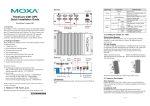
Ethernet Port
The two 10/100 Mbps Ethernet ports (LAN 1 and LAN 2) use RJ45
connectors.
Front View
LCM Display Panel
19-inch
Rackmount Ear
ThinkCore DA-660-8/16-CE
Quick Installation Guide
First Edition, May 2006
Reset Button
LED Indicators (System Status, LAN, Serial Tx/Rx)
Push Buttons
Rear View
Power Input (100-240 VAC/VDC)
RS-232 Console Port
RS-232/422/485
Serial Ports
RJ45, 50 to 921.6 Kbps
RS-232/422/485
1
2
3
4
5
6
7
8
9
10
11
12
13
14
15
16
LAN2
Power Input
LAN1
100-240 VAC/VDC
Console
10/100 Mbps Ethernet x 2 (RJ45)
ON/OFF Switch
1. Overview
LED Indicators
ThinkCore DA-660 products are RISC-based ready-to-run embedded
computers designed for industrial data acquisition applications. They
feature 8 or 16 RS-232/422/485 serial ports and dual Ethernet ports based
on the Intel XScale IXP-422 communication processor. The casing is a
standard 1U, 19-inch wide rack-mounted rugged enclosure. This robust,
rack-mountable mechanism design provides the hardened protection
needed for industrial environment applications, and lets users easily
install DA-660 on a standard 19-inch rack. Using ThinkCore DA-660,
you can easily build a control system with distributed architecture for
embedded technologies, such as SCADA systems, plant floor automation,
and power electricity monitoring applications.
The following LED indicators are located on the front panel of the
ThinkCore DA-660.
LED Name
Ready
LAN1-2
P1-P16 (Tx)
P1-P16 (Rx)
LED Color
Green
Orange
Green
Green
Off
Orange
Off
Pin
Signal
1
ETx+
1
8
2
ETx3
ERx+
6
ERxSerial Port
There are eight serial ports (P1 to P8) on DA-660-8 and 16 ports on
DA-660-16. All serial ports use RJ45 connectors. Each port can be
configured by software as type RS-232, RS-422, or RS-485. The pin
assignments are shown in the following table:
LED Function
Power is on and functioning normally.
10 Mbps Ethernet connection
100 Mbps Ethernet connection
Serial port is transmitting data.
Serial port is not transmitting data.
Serial port is receiving data.
Serial port is not receiving data.
Pin
1
2
3
4
5
6
7
8
4. Installing Your ThinkCore DA-660
2. Package Checklist
Before installing ThinkCore DA-660, verify that the package contains the
following items:
y 1 ThinkCore DA-660
y 19-inch Rackmount Kit
y ThinkCore DA-660 Quick Installation Guide (this guide)
y ThinkCore DA-660 Document & Software CD
y Cross-over Ethernet cable
y CBL-RJ45M9-150: 150 cm, 8-pin RJ45 to DB9 (M) serial port cable
y CBL-RJ45F9-150: 150 cm, 8-pin RJ45 to DB9 (F) console port cable
y Power Cord
y Product Warranty Booklet
Notify your sales representative if any of the above items is missing or
damaged.
3. ThinkCore DA-660 Panel Layout
NOTE: Two models of ThinkCore DA-660 are available. DA-660-16 has
16 RS-232/422/485 serial ports and DA-660-8 has 8 RS-232/422/485
serial ports.
Desktop Mounting
Place your ThinkCore DA-660 on a clean, flat, well-ventilated desktop.
For better ventilation, attach the 4 pads from the desktop kit to the bottom
of the unit, and leave some space between the DA-660 and other
equipment. Do not place equipment or objects on top of the unit, as this
can cause damage to the product.
Rack Mounting.
ThinkCore DA-660 can be mounted on a standard 19-inch rack. Use the
enclosed pair of L-shaped metal plates and screws to fasten your DA-660
to the rack cabinet. Two options are available. You can lock either the
front or the rear panel of the DA-660 to the front side of the rack. Each
L-shaped plate has 6 holes, leaving two outer or inner holes open for
other uses.
5. Connecting Your ThinkCore
Power Connector
Connect the 100-240 VAC/VDC power line to ThinkCore DA-660’s
power connector. If the power is properly supplied, the Ready LED on
the front panel will glow a solid green when the OS is ready.
RS-232
DSR
RTS
GND
TXD
RXD
DCD
CTS
DTR
RS-422
--TXD+
GND
TXDRXD+
RXD-----
RS-485
----GND
--Data+
Data-----
—2—
8
Console Port
The console port is an RJ45 RS-232 port. It can be connected to a V90 or
GPRS modem via PPP. The pin definitions are the same as for the serial
ports.
Reset Button
Press the “Reset” button on the front panel continuously for at least 5
seconds to load the factory default configuration. After the factory default
configuration has been loaded, the system will reboot automatically. The
Ready LED will blink for the first 5 seconds, and then maintain a steady
glow once the system has rebooted.
LCM Screen
ThinkCore DA-660 has an LCM screen on the front panel. The LCM can
display 16 columns and 2 rows of text. After the DA-660 successfully
boots up, the LCM will display the model name and firmware version as
shown:
D
V
A
E
R
6
.
6
1
0
.
0
1
6
Push Buttons
There are four push buttons on the ThinkCore DA-660’s front panel.
These buttons are used to operate the LCM. Going from left to right, the
buttons are:
P/N: 1802006601000
—1—
1
—3—
Button Action
MENU Displays the main menu at any time.
Scrolls up through a list of items shown on the LCM screen’s
︽
second line
Scrolls down through a list of items shown on the LCM
︾
screen’s second line
SEL
Selects the option listed on the LCM screen.
Real Time Clock
ThinkCore DA-660’s real time clock is powered by a lithium battery. We
strongly recommend that you do not replace the lithium battery without
help from a qualified MOXA support engineer. If you need to change the
battery, contact the MOXA RMA service team.
ATTENTION
There is a risk of explosion if the battery is replaced by an incorrect type.
6. Powering on Your ThinkCore DA-660
To power on the ThinkCore DA-660, connect the power line to the
DA-660’s AC/DC power connector (located on the right side of the rear
panel) with the power cord that is shipped with the product. Then, turn on
the power switch. It takes about 30 seconds for the system to boot up.
Once the system is ready, the Ready LED on the front panel will light up,
and the DA-660 will display its model name and firmware version on the
LCM display.
7. Connecting Your ThinkCore DA-660 to a PC
There are two ways to connect the ThinkCore DA-660 to a PC: through
the serial console port or via Telnet over the network. The COM settings
for the serial console port are: Baudrate=115200 bps, Parity=None,
Data bits=8, Stop bits =1, Flow Control=None.
ATTENTION
Remember to choose the “VT100” terminal type. Use the CBL-RJ45F9-150
cable included with the product to connect a PC to DA-660’s serial console
port.
To use Telnet you will need to know DA-660’s IP address and netmask.
The default LAN settings are shown below. For first-time configuration,
you may find it convenient to use a cross-over Ethernet cable to connect
directly from the PC to the ThinkCore DA-660.
Default IP Address
Netmask
192.168.3.127
255.255.255.0
LAN 1
192.168.4.127
255.255.255.0
LAN 2
Once the DA-660 is powered on, the Ready LED will light up, and a
login page will open. Use the following default Login name and
Password to proceed.
Login: admin
Password: admin
—4—
8. Configuring the Network Settings
Normally, you are required to change the IP address of the ThinkCore
DA-660 as it may be located in a different local network from that of
your development workstation. Use the netconfig utility to complete this
task. Before using this utility, type netconfig -h to examine the usage of
the command.
\> netconfig -h
Usage: netconfig –n <“LAN1” or “LAN2”> [-m <netmask>] [-d
<DNS server>] [-g <gateway>] [-i <IP address>]
For example, let us assume your development workstation has a LAN
port at 192.168.1.x and the Domain Name Server (DNS) is at 192.168.2.6.
Execute the following command to change the network settings on your
ThinkCore DA-660.
\> netconfig –n LAN1 –i 192.168.1.5 –m 255.255.255.0 –g
192.168.1.254 –d 192.168.2.6
Type netconfig to view the new settings.
\> netconfig
LAN1 Interface Configuration:
IP Address: 192.168.1.5
SubNet Mask: 255.255.255.0
Gateway: 192.168.1.254
DNS: 192.168.2.6
LAN2 Interface Configuration:
IP Address: 192.168.4.127
SubNet Mask: 255.255.255.0
Gateway:
DNS:
9. Developing Your Application
Application development on the ThinkCore DA-660 takes advantage of a
number of well-known tools that are provided by the Windows
environment on programmers’ workstations. These tools are easy for
Windows programmers to use. The following development tools are used
for Windows Embedded Application Development.
z VB.NET/C# Applications: Use Visual Studio 2005
z VB.NET/C# Applications: Use Visual Studio .NET 2003
z C/C++ Applications: Use eMbedded Visual C++ (eVC) 4.0
Visual Studio 2005
You do not need to install additional packages.
Visual Studio .NET 2003
1. Install Visual Studio .NET 2003
2. Install Windows® CE Utilities for Visual Studio .NET 2003 Add-on
Pack (550KB) for VB .NET
3. Import Compact .NET Framework SDK
eMbedded Visual C++ (eVC) 4.0
1. Install eMbedded Visual C++ 4.0 (230 MB)
2. Install Service Pack 4 for eVC 4.0 (68 MB)
3. Install MOXA Windows® CE 5.0 C/C++ SDKs
—5—
Developing applications with eVC 4.0 and MOXA SDKs
1. Start Microsoft® eMbedded Visual C++ 4.0.
2. From the File menu, choose New.
3. Choose the Projects tab and then select the type of application.
4. In the Project name box, type project name, and click OK.
5. Choose the type of application that you want to create and click
Finish.
6. On the Build toolbar, choose the MOXA DA-660-CE SDK, the type
of run-time image (Release or Debug), and the DA-660-CE device.
7. Write your application code.
8. From the Build menu, choose Rebuild All to build the application.
9. When you complete your application, use the web-based management
system to upload it to the target computer.
Developing a VB.NET / C# application with .NET Compact
Framework
1. Start Microsoft® Visual Studio .NET 2003.
2. From the File menu, choose New Æ Project.
3. Choose the Project Type and then select the Smart Device
Application type of application.
4. In the Project name box, type a name for the project, and click OK.
5. Choose the Windows CE target platform.
6. Select the project type and click OK.
7. Write your application code.
8. From the Device toolbar, choose Windows CE.NET Device.
9. From the Build menu, choose Build Project or Rebuild Project.
10.When you complete your application, use the web-based management
system to upload it to the target computer.
10. Environmental Specifications
Power requirements
100 to 240 VAC/VDC auto ranging
(47 to 63 Hz for AC input)
Dimensions (WxDxH) 480 x 198 x 45 mm (including rack-mount ears)
440 x 198 x 45 mm (without rack-mount ears)
Operating temperature -10 to 60°C (14 to 140°F), 5 to 95% RH
Storage Temperature -20 to 80°C (-4 to 176°F), 5 to 95% RH
Serial protection
15 KV ESD for serial port
Magnetic isolation
1.5 KV for Ethernet
Regulatory approvals FCC Class A, CE Class A, UL, CUL, TÜV
Warranty
5 years
Copyright © 2006
Moxa Systems Co., Ltd.
All rights reserved.
Reproduction without permission is prohibited.
Tel: +886-2-8919-1711
Fax: +886-2-8919-1722
www.moxa.com
[email protected]
—6—