1
I
CRRFT_MRN_
CAUTION:
ReQd _FETY
Am
E TiLL
RULES and
BNSTR_TaONS
c=refullv
,, AssembBy
O_rating
o Maintenance
, RepOt Par_s
ROEBLrC"K
PART NO. 770-7764
AND
CO., Chl_U.
(_0684
U_
PRINTED IN US.A,
'rrr_'_:r_
- ...
°
'
._-_'rrr_r_'_r_r___-_qr_rr_
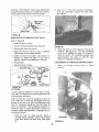
FULL:ONE YEAR WARRANTY
or one year from tile date (_f pur.chase,
orkmanship in this TILLER at no charge
the TILLER is used for commercial
Sears will
repair any defect
this warranty
i_ material
or'
,,
applies for only
i
Warranty service is available by contacting the nearesi Sears store or Service Center
throughout the United States.
This warranty gives you specific legal rights, and you may also have other rights
i
thirty days from
or rental purposes,
!
[he date of purchase,
_,
Which vary from state to state
_.
Sears, Roebuck and Co."
Sea_s Tower
_,
I_
BSC-4.14::
==
_.
C h i e,.,-i_l.d,,
IL 60684
MPORTANT
It is suggested that this manual be read in its entirety before attempting
manual in a safe place for future reference and for ordering replacement
This unit is shipped WITHOUT
for proper fuel and amount.
Your tiller is a precision
at all times.
GASOLINE
or OIL. After assembly,
piece of power equipmei!.t,
SAFE OPERATION
not a play thing.
2.. Never allow chltdren to operate a power tilter.
Only persons well acquainted with these rules
of safe operation
shou}d be allowed to use
your til ler.i
7, Do n,ot stand
tn fi'ont
starttng the :eilgtne.
of
tiller
9, Do not leave thetll"lar
e6gtne running,
the
una{t.ended
of the tiller
caution
tl.
Do not fill gasoline
tank while engine is
running. Spilling gasoline on hot engine may
cause a fire or explosion.
12
Do not run the engine while indoors.
gases are deadly poisonous.
with
16_ Before attempting
to
and other objects from
and be
sure
the
completely.
DisconneCt
and ground to prevent
while
thi_
{he
I)o not.walk :in front
engine is ru.nntng,
extreme
Exhaust
after
the
!5_ Use caution when ti'lling near buildings
arid
fences, rotating
tines can cause damage oi'
injury.
lever
8, Do not blac_ feet and ha.nd.S,o,n or..near
tines _vhen st_arttng the engine' 5r white
eng'lne is i'U_rilng,
l&
of thts manual
that could
the shift
the
exercise
Keep this
14, Before any maintenance
work iS performed or
adjustments
are made, remove the spark plug
wire and ground it on the engine block for
added safety,
4, Do not operate equipment
when barefoot
or
wearing open sandals_ Always wear substantial footwear,
6, Do not start the engine unless
is in the neutral iN) position,
Therefore,
section
13, Be careful not to touch the muffler
engine has been rupning, tt is hot°
3, Keep the area of operation
clear of all
persons, particularly small children and pets,
clothing
see operating
or operate.
PRACTICES FOR T LLERS
1, Read the Ope[ating
and Service
Ownerts
Manual carefully. Be thoroughly
familiar with
the controls
and the proper
use of the
equipment.
5. Do not wear loose fitting
get caught on the tiller,
to assemble
parts.
remove rooks, bricks
tines, stop the engine
tines
have stopped
the spark plug wire
accidenta! starting.
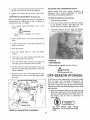
I 7, Check the fine and engine mouhttng bolts at
frequent Intervals for proper tightness.
18. Keep all nuts, bolts and screws tight to be
sure ,the equipment
ts in safe working
condition,
with gasoline in
19. Never store the equlpmetlt
the tank tnstde of a building where fumes may
reach an open flame or spark_ Allow the
engine
to cool
before
storing
tn any
enclosure,
wh{te the
A spark arrest muffler is available as an accessory part, "The part number
mendel. Check muffler legal requirements
in your area
3
is listed in the parts section
Of this
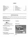
INDEX
Warranty
.................
Safe Operat ion Practices
................
Introduction
..................
Contents of Hardware Pack ...............
Tiller Identificat.ion
.....................
Assembly instructions
.....................
Engine Preparation
.........................
Adjustments
....................................
Controls.
_.; ...... : ............
, .................
Operation .................................
2
3
4
5
6
7
9
9
9_
12
Tilling
.................
Titling Hlttts .........................
Maintenance .................................
Off-Season Storage
...............
Transmisstor_,.- Repair Pads
....
Tilter--Repair
Parts ....................
Tiller Accessories
..............
Engine--.Repair
Parts ....................
How "fo Orde.r Repa!'r.Par_ts ......
13
13
13
17
20
22
25
26
Back Cover
INTRODUCTION
This Product has been designed,
and performance.
engineered
and manufactured
to give you the best possible
dependability
Should you experience any problem you carinot easily remedy, please con'tact your nearest Sears, or
S impsomSears
Service Department° They have well qualified; competent trained technicians
and the proper
tools to service Or repair this unit.
PRE...A.SSEMBLY
3. Gas (regular)
4. Cleaning
_
NOlrE
PARTS IN CARTON
The right and left side of your tiller
is determined
from operator's position.
Before any step is undertaken, the instructions
that step should be read through..
for
TOOLS REQUIRED:
to (2) 7116" Socket, open or bOx Wrench,
2. (1) 9116" Socket, open or box wrench..
3. (1) V4" Flat Screwdriver,
4. (t) AdjustableWrenoh,
MATERIALS
REQUIRED:
1. Funnel (for-gas and olt,-_ NOTE: DO NOT MIX)
2. S..A_E.,-30 OtI_2%
rag
pints
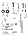
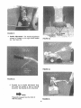
FIGURE !,
4
K
©
G
j
Gk
H
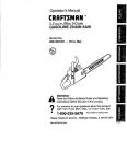
FIGURE 24 {SHOWN
IN FULL SCALE)
_NOTE
THE
LETTERS
LISTED
BELOW
WILt,
BE
REFERRED TO THROUGHOUT THE FOLLOWING
TEXT FOR EASIER
HARDWARE
IDENTIFtCATION,
LiST OF CONTENTS
A
B
C
P
E
F
G
H
(2)
(2)
(2)
(2)
(!)
(1)
(3)
(1)
IN HARDWARE
PACK :
Shoulder Bolts
Fiat Washers
Bellevilte Washe, s
Hex Nuts 3/8-16 Thread
Hex Screw 3f8_t6 x 1..50" Lo_g
HexScrewl/4.20xl.75"Long
Flat Washers 31B"
Hex Locknuts3t8-24Thread
J
K
L
M
N
O
P
Q
(!)
(2)
(2)
(t)
(1)
(1)
(1)
(1)
Compression
Spring
Hair Pin Cotter
Self Tapping Sorews
Hex Nut 1/4-20Thread
Lever
Ferrule
Hex ,Jam Nut 318-24 Thread
Hex Locknut 3/16 Thread
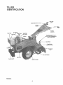
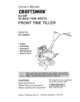
TBLLER
mDENTi:F6CAT ON
GearShill
Lover
,"
,die
Assembly
011Di
Fuel Tank
Spsrk Plug
Wire
Fuel Cap
i
Tine:(,Enga_er_e.nt) Lever
NQTE: Wheel (Engagempn_)
.=-
Lever on other sld_
*'_...........
Depth Stake
....
Depth Stake
Adjustment Lever
Dum
Tine Shield
Flap
B_|t Cover
Counterweight
FIGURE 3,
S
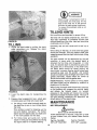
ASSEMBLY
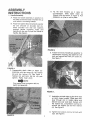
INSTRUCTIONS
Dr "l!p. the tilte'r fOrwa?d, so it rests on
_o.unter_ejghl,
$Iide
d.ePth stake
up
thrpughUl}er
as s.ho,wn in, .figure 6, Pdll
rele&se #in On tiJier to loc_4 in place.
1. Handle Assembly
A. Place the handle assembty tn position on
the tiller so that tile holes in Ilandle line up
with holes in nqounting bracket..
B. Place flat washer (B) and belleviIte
(C) over shoulder
on shou!der
Place sl]oufder
bolt ai_d two
thro, ugh
handle
mounting
s'eq.Ure wH.h he× nut (D) from
handle. See !!guPe 4.
:
washer
bolt (A)
Washers
h ot.es and
ihe inside of
,+FJOURE6,
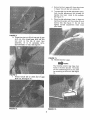
E. At.ta_.h ,front epd of [email protected] bai" .assembly !o
tr_ni_mlssion hodsiag: Slip depth:bar:over
bolt _,nd secu_te w.fth hair ptn :9otter (K).
See l.0.re,7:
FIGURE 4.
C.
Preassemble
depth stake .to depth bar
assembly with hex sdrew (E), flat washer
(G) and hex locknut (Q)o See figure 5.
T_gl_tep nut an.d :boU, b_J.t d0. net
tlOhtem ':P_,i.hs
mu_t 'pivOt.
Flat W_Sh.er must go against
depth bai" assembly,
over
s!:qt on
" 'I_::
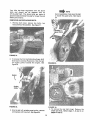
Ass..i_mB.le r_0tched edge:of gear shi-.ft lever
so n0(o.h faces forwa[d._:: P.!ac6gear shift
ie.vej" tl_rough slot th handle #An.el a.nd
66{t0._ h0.,leove_"we!d s{bd,-Secure:Wiih
:
t=l_t w_,ller'(G).,
oompre_s!e n .Sp(iog (J)i
andt.her fiat washer,(G)
ahd: hex IOckhui
(H). See f!Ljbre'8.
G, Tighten hex tocknut
stud. See figure 8.
until nut is Mush with
J_
Secure ferrule in gear shift lever (as shown
in figure 10) with hair p_n cotter (_),
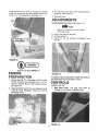
K, To assemble the handle adjustment
lever,
hook handle ad]ustmen.t' t:od '(already on
handle) into lever, Hoot_ to the outside.
See figure 11,.
L.
Place handle adjustment
tevet in place on
handle and secure with he× sci'ew (F) and
f0cl{nut (M), See figure 1t. Do not over
ttgilten
handle
adjustment
lever must
pivot freely,
F GU.RE
i1.
M., ThrOttl e Control
[.ever,
NOTE
-,
]_he throttle control may have four
holes in the lever bracket The holes
on the outside edge are to be used
for mounting on this unit., See figure
12.
FIGURE 10.
Placethrottle control leverup through the handle
panelandsecurewith two self tappingscrews(L),
using a t/4" flat screwdriver: See figure !3
3
Fill fuel tank with c_ean fresh regular grade of
gasoline,
see figure 14
4
Open gas valve.
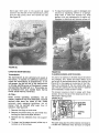
ADJUSTNgNTS
Handle Adjustment
Lever. (See figure 15.)
NOTE
Figure 15 is viewed
of handle panet.
from
the bottom
A. Use if not enough free play;
B. Normal setting.
C. Use _f pin wi{t not withdraw c0mpletely
bracl<et_ *
from
FIGURE 13,
Engine ts shipped
Wi{bout oil,
ENGINE
PREPARATION
FIGURE .15.
To make the above adjustment !o0sen he x io_knut
a_nd'_e_os|!iOn the rod Ifi Hole A, B Or C,
1, Before starting. Fill crankcase with 23/4 pints
of SAE 30 heavy duty detergent oit or to full
mark on dipstick, Be sure that engine is !evet,
See figure 14, ..
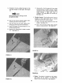
CONTROLS
Location and Use.
1. Gear Shilt Lever: The gear shift lever is
located in the center of handle panel,
2. Change 0(l._ter first 2 hours of operation and
every 25 hours the.re_ter,
CheGk 0)_ eve_ 8
operati.ng h0grs, _ •
FIGURE 16.
FIG
9
A. Forward (1 thru 5)--. Move the lever t.o the
left and forward for each gear, See figure
16,
F, Reverse (R) .... Pull the gear shift lever back
(upward) slowly to obtain, reverse, Always
use caution when using the reverse_ When
u_tng {:everSe, .if gear' shift
lever is
re}eased It'w[tl sqap. ba_k int_: neutral (N),
S e_'figure 18,
_NOTE
The engine must be running tO move
the gear shift lever,
".....
B_
2
Use (1) first and (2) second gears when
breaking the sod for the first time_
A. St_op--Pull lever back (upWard) to stop the
engine, See fig0re 19,
Use (3) third and (4! f0,urth gears when
till!ng soil which has been tilled before_
D. Use (5) fifth gear for pulverizing
transporting the tiller,
E Neutra! ,(N)_Move
"N,"
See figure
B, Start_Push
throttle oontrol lever forward
(down) to start position.. See figure 20,
solt or for
lever to detent
Throttle Control: The throttle con'trol iever is
IQcated on the right' h_nd side of handle
panel arid _ontrels the engine speed,
marked
17.
FIGURE 19.
FIGURE t7,
3. Ch0ke: The choke is located on the e.ng{qe
Jus.t .l_elow t'tle air cleaner.
To choke the
engine move the lever down, See figure '21,
FIGURE 18.
10
FIGURE 21.
,::-:;.-
4,, Handle Adjustment:
The hand!e adjus{ment
release is located, on the right har_d handle
bar, See figure 22°
FIGURE 23.
FIGURE 24.
FIGURE 22.
A. Squeeze up on handle adjustment lever
and place the handle in One Of nine (9)
positions
See figures 23, 24, 25 and 26.
_NOTE
Figure 23 is viewed from the front of
tiller for clarity.
FIGURE 25,
11
6, Wheel Engagement Lever; The wheel engagement feverl_ lb(_ted on the right side of tilier_
A. T0 engage wheels hiov_, the lever out_vard,
To disengage or stop W!_eeis move lever
iriWard.. See figure 28, ,
RGURE
26.
WARNING
The gear shift lever must be in
Neutral (N),posltton befQre engaging
or. diseligag!ng
tJte .tir_e ahd wheel
engagement levers.
.....
5. Ttne :Engagement Levet: The ttne engagement
lever is located on the left side of tiller.
NOTE
FIGURE _8.
It may :be necessary io slightly engage gear shiftlever tb opemtb.
OPEBAT{O.N
A. TO e_ngage tines move the lever outward.
To diseng&ge tlnes rdove (_ver Inward; See
ffgL_re 27,.
TO START ENG|N E:
BE.SURE NQ ONE.IS STANDING IN
FR0NT oF THE TiLt=ER!.WHiLE .'THE
ENGINE: IL.SRUNNING", OR BEING
STARTED'.
1. Place t,he gear shift
lever
position,
See figure 17
in
neutrat
2. Plaae the tine engagement
lever
disengaged position.
See figure 27_
%
3. Place the wheel
,
,
12
in
the
lever in the dis_
engaged .position, See figure 28.
P!ace the throttle
control
lever
position.
See figure 20,
in
FAST
Choke engine. Move choke tever down. See
figure 2t_ Once the engine starts, move the
lever up,
5_
FIGURE 27,
er_gagement
(N)
Stand at side of tiller, grasp the starter handle
and pul! out rapidly, Return it .slowly to the
engine_ Repeat as necessary.
See figure 29,,
When tilling, if a hard spot or rock is
encountered,
the tines may lift the
back Of the tiller out Of the ground
and start to walk across tlle ground,
To correct this problem raise up on
the handles,
TiLL:iNG:Hg NTS
Soil conditions
The t!nes will not. readily penetrate dry, hard s0tl,
This may con.tribute
to ex6essive bounce and
dill!out| handling of.the tiflei. Hard'soii should be
moistened prior to tilling,
,'y :
FIGURE 29.
a_e imp.ortaht for proper tilling.
':'
TILL!NrG
ExtremelY
clump,
1., Adj_is.{the depth stat<e bY pullJ.ng: the depth
stake
atJjiJstment
pin, Release the depth
30.
Wet soi! wilt cause .soil 1o ball up or
When tilllhg in the Fall, all vines and long gt_ass
should be removedo This will preveht vibes from
wrapl_:lng around _he fine s h_ft Whlcl_ slows ttl!ing
operation,
The best method will be determined
by the soil
condition,
In some soils, the desired depth "is
obtained the first time over the garden, tn other
so.ils, the desired depth Is obtained by going over
the garclen two or three times_ In the latter' t_ase,
the depth stake should be raised (raising
the
depth stake increases diggliqg depth) before each
suc.oeeding pass over the garden, and passes
st'io!jtd be made across the ierigth and width of the
garden alternately,. Rocks' which Are turned up
should be removed from thega¢dei_ area.
Handle Pressure: Eurther O0nt#ol of ttll!ng depth
a nd,t_:avet speed can be ol_tained by variation of
p_es_.ure on t_he handles.
2, Lower
tiller,
the depth
stake for transpdrtlng
When .using the depth stake e(downward pressure
onthe, handles Will increase the working depth
ahd 're.duce
the' f0cwai'd_ speed.
An upward
ptes.sti.r.e o,n tlie handleswill
reduce the working
deistic:and tncrease the fo_ard
speed, The type of
sotl arid wi_kt_qg conditioris
Wilt determine
the
the
3. Engage wheel engagement
lever, select gear
on handle panel and ti!let will propel itself:
actual se.t.t;!ng Ofthe;.deptl_
_J!ake,
tVlAINTENANCE
A, For tilling !n sod, raise the depth stalke so
the depth bar is one to two inches above
tt_e ti:nes.
BELT RE,PLACEMENT:
Ti_is sett!ng {s _ised for breaking up the
sod .and shallow Cultivation.
For further
depth ra}se theedepth stake and -make one
or two more passes over the area,
_o not use a'n off:the-shelf belt.
If belt replacemer_t is required, ordei" belt or belts
by part number from your nearest Sears Service
Center.
B_ For fitting loose and sandy soil, further
depth tn tilling can be achieved by raising
the depth stake to its higllest setting.
Part No. 754-0220
5/8" x 27" Short Belt
13
Part No. 754-022t
5/8" x 52" Long Beh
Your tiller has been engineerea with the above
belts and Should
not be replaced
with
an
off-the-shelf
belt. The above belts are made of
special material (Kevtar Tensfl.e) for longer life and
better petformance.
REMOVING
t.
AND REPLACING
._
NOTE
Upon reassembly make sure the belt
is inside the guide ptn s. See .figure
34.
BELTS.
Remove belt cover; remove two bolts, two
nuts and four flat washers. See figure 31.
2, To remove th e front belt (short) pui! gear shift
lever back to reverse (R) position. S!]p the belt
off ehglne pulley towards the engine, See
figure 32.
FIIGURE 33._
Engine
\
FIGURE 32.
FIGURE 34,
4, To remove the rear. belt (long). Remove the
small belt first, follow steps t, 2 and 3 on
pages 14 and 15.
3_ Slip the belt off variable speed p u!|ey, remove
and replace with new bert. See figure 3.3,,
14
5_ To clean foam element, wash in detergent and
sotution by squeezing similar
to a sponge.
Wrap foam in cloth and squeeze dry. Coat
element with two tablespoons
of engtne oil,
Move gear shift lever to the second (2) speed
position. Stip tl_e belt off the transmission
pulley.
Pull the idler pulley down and remove the belle
See figure 35
Squeeze
to distribute
and remove excess oil,
FIGURE 35,
CARE AND MAINTENANCE:
Transm|SsJon:
FIGURE 36.
CLEANING
:,
Any fuel or oil spilled on the tiller should be wiped
off promptly,
Dirt,:'_eaves anct other debris must
not be left t_ accumulate
around the cooling fins
(figure 37) or the eng[ne o.r on any part of the tiller.
C!ean t!le underside"'df: the tine shield after each
use, The dti't washes off the line easier if washed
off immediately
instead of after it dries.
The transmt_,_lonts.pre-tubrtcated
and sealed at
the factory, it requires no addfttona( lubrication
unless the"transmisslo8
t8 dtSassembte& To fitl
with grease, lay t#e left half of the transmfsston
on Its stde, add 28 Qunces of Pta.s{tlube #1 grease
and assemble the rtgh_ half to it. Thfs grease can
be purctfased
from your nearest Sears Service
Center,. (Order Part NO. 737,-0133,)
Tt_e blower housing is held in place with three
screws, One on the top of the engine and two on
the bottom:, See figure 37.
SPARK PLUG
Adr Fitter:
Under normal
operating
conditions,
the air
cleaner, .located on top of the earbUretor, must be
sei'viced ariel; everj ten hburs of use. Under
extremely
dusty opeta.tirig:'b0tldit!ons,
the air
eleanor tfiust be.,sei_i¢ed
dfter eyery hour of
operatton, See fjlgtJre36.
t.
ENGINE AND TINE AREA
Dirt
Remove the _iing nut and cover.
2. Remove the S{_cend wing n,ut and metal disc
hotd[ng: the foam and paper element.
3. Remove
b:ase.
t!_e {We elements
from
4. To clean, tap the paper element
bottom) on a flat surface.
the support
(either top or
The spark plug gap shouid be cleaned and reset to
a &030-inch
clearance every 25 hours of engine
15
operat!on.Seefigure38, Sparkplug replacement
is recommendedat the star! of eachttlfer season;
checkengine,pal;tslist for correctplug'type,
2, After the elf has been drained completely
from the crankcase,replacethe drain plug
and tighten.
FIGURE 38,
GASOLINE
FILTER AND SHUT,OFF
VALVE
Refer to figure 39
1_ Close the shut-offvaf.ve.
2., Loosen the thumb se.r._w be.tow the bowl,
FiGUre40."
3. Remove.ahd
;& With the t i!ler on level ground, remove, the
clipsttck.
See figure t4:
Fill the cranf_case
uiqtil the oil reaches full mark, Fi.l! sl£wly to
avotd air locks: The crankqase should hold
apprO'kimate[y
2,_/4 pints
of SAE"30
type
engine oi.L Replace thedipstick.
clean the scr_een;
4. Open the §hut-o!f
valve to see if gasoline
ft_ws freely from the gas,91tne tank._
5, Qle_.n the bowl and,.scr.,eeh. Use alcohol or
acetone to c)ean ttie pa,lrts " "ii you find a
gumf-ny, v'arnlsh-ltke sL{bstadce in the bowl,
ADJUSTMENT
6. Reassemble,
7 Qpet_ the sh'at-off valve.,
:
OF THROTTLE
1. Place the
position..
Shut-Off'Valw
FIGURE 39.
Oil Change
To avoid spilling gasoline on your lawn or drive..
way, plan to change the oil when the gasoline tank
and carburetor are empty.
After the first two hours of operating a new en~
gine, drain the oil from the crankc_ase while the
engine is still hot and refill the.crankcase
with
new oil; thereafter change the ott after ev&;r_,,25
tiours of operation., THis proc.edbre ensures for
minimum
wear of engine parts and provides for
virtually trouble-flee
opera'ti'Qn. To change the oil,
proceed as follows:
t.
With the tiller on level ground,
place a
suitable metal container under the oil drain
ptug, then remove the drain plug. See figure
40
Screwdriver
FIGURE 41.
tB
throttle
CONTROL CABLE
cor_trol
lever
in STOP
2
Loosen the casing clamp screw and move the
thro!fle control wire in as far as possible,
3. Tigl_ten the casing clamp screw
See tlgure
41,
CARBURETOR ADJUSTMENT See figure 42,
Minor carburetor
adjustment
may be required to
compensate
for differences
in fuel, temperature,
altitude and load, To adjust:
1. Turn needle
closes.
valve
_
clockwise
until
it
just
CHOKE
Proper choke
and stop
switch
operation
is
dependent
upon proper adjustment
of remote
contfols on the powered equipment.
TO check the Opi_ration o_ the Choke:
1. Remove the air cleaner,
2. Push the throttle control all the way forward
to the START position,
See figure 20. The
choke should be closed_ See figure 43,
3. T'he engine sllould shut of_ whBn the tt_rottle
control is all the way back (STOP position).
CAUTION
Valve may be damaged
1oo far._
2. Open needle
wise,
ADJUSTING THE CARBURETOR
by turning
valve 1.118 turns
.'r
counterctock-.
3.. Close the idler valve in the same manner and
open 1-1 18 turns.
4. Start time engine
5. Turn the
misses.
needle
valve
in until
the
engine
6. Tl_en turn it out past smooth opetating
until the engine runs unevenly.
point
FIGURE 43.
7. Turn the needle valve mid-point
between
two Settings so the engine runs smoothly.
the
TIRE PRESSURE
Tires should
8. Set the throttle in the idle (slow) position and
set the Idle speed adjusting screw until a fast
idle is obtained,
9. With the throttle still in the idle position, turn
the idle valve tn and out until the engine idles
smoothly.
Idle Speed Adjusting
Screw
Idle Valve
be Inflated
from 8 to 15 p.s.i,
_CAUTION
Do not exceed 30 p.sJ,
OFF°SEASON
STONAGE
tf the tiller is to be inoperative for a period longer
than 30 days, the following
precautions
are
recommended.
Keep your tiller in a weatherproof
dry area. If stored for over 30 days the following
steps will protect the essential engine parts from
gum deposits.
1. Working outdoors, drain all fuel from the fuel
tank. Use a clean dry cloth to absorb the small
amount of fuel remaining in the tank, then run
the engine until all fuel in carburetor
is
exhausted.
,
,
eedle Valve
FIGURE 42. CARBURETOR
ADJUSTMENT
DO NOT
SMOKING,
FIRE.
DRAIN
FUEl.
WHILE
OR IF NEAR AN OPEN
2 Drain all the oit from tile crankcase (this
should be done after the engine has been
operated and Is still warm) and refill the
crankcasewith clean new oft, See figure 40.
Fuel, Replace any summer gasoline-on hand or in
the fuel tank with fresh winter-grade
gasoline. Use
lead*free or leaded "regular"'
grade automotive
gasoline.
Winter fuels have additives
for faster
starting,
Keep fuel tank full,,
3. Disconnect
the spark plug wire and remove
the spark plug from the cylinder'. Pour about
six drops of engine oil Into the cylinder, and
then pull the recoil starter several times to
spread the otl on the cylinder wal!, Replace
the spark plug, but DO NOT connect the wire.
4, Clean
the
thoroughly.
engine
and
the
entire
NOTE
Many automotive gasolines rio longer contain "deqcer."
A can of gas*
line de, icer fluid added to your gasoline supply wi_{ h_tp maintain
the
engine's winter reliabll!ty,
tiller
5. Wipe tines with oiled rag to prevent-rust,,
Cold Starting Hints
TtLLER INSTRUCTIONS
FOR W1NTER
OPERATION (under 40°F,)
1. Be sure to use proper
gasoline.
Engine Lubrication. Drain the sur_mer engine oil
while engine is warm. =Refitl.._wit[h new "winter
grade" oil, Run 'engine until wa'rmto_istribute
the
new winter oi!..
2. Declutch
all possible
3, Set governor
control
winter-grade
external
oil and
loads.
at low-speed
position.,
4. Turn carburetor
needle valve approximately
1J8 turn
counterclockwise,
(Richer
fuel
mixture)
This will
improve
cold weather
starting and operatiol_,
Use oil "fdr sei'v:ice? 80, SD, dr SE, Use 5W-20 or
5W-30. 'If not available;, use. tOW; o.r t'0W,-30.
18
19
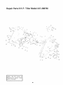
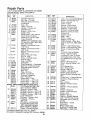
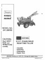
Repair Parts 8 H=P. Tigter Mode! 247°2!t8780
3
/
7
6
!: ,{
2O
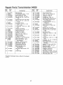
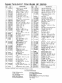
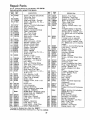
Repair Parts Transmission 04820
_F_
PART
........
R'_!
..........
oE C,.,P:JON
PART
.....................
DESCRIPTION
I
i
2
3
4
5
741-0t55
04822
738-0379
714-0122
750-0379
Bal! Bearing
Transmission
Ass'y,,,.-,R,H.
Input Shaft 518" D!a,
Sq.. Key 3116 x -75 Lg.
S pacer.637,.D,
x.781 O.D.
28 1717-0382
29 72'I-0102
30 712o0138
3,
736-,0329
o2 741_0229
6
7
7t 7-0210
750-0378
x 85
Sprocket
9 looth ,50" Pitch
Spacer .637 I.D, x .78t O.D_
x 1,44
343 04826
713-0226
8
9
21
22
23
24
721-0162
741-0862
732,-0863
719-0237
7!9-0238
25
7!0-0601
Tine Shaft Ass'y,
FI-Wash. 1.0 t_D, x 1.62
CoD x 090
Flange Brg, !.001,D, x 1.188
O.D.
Gasket--Housing
Transmission
Ass'y.--L,H
Bearing Housing
L-Wash, _/_ Scr.*
Hex Nut l/4-28Thd,*
Seal 1.0" LD. x I.,38 O.,D
Beltevi]leWash.
L-Wash. 318"Scr,"
HexCenL L._Nut3f8-24Thd_
Shift Yoke Ass'yo_L. H.
Shift Yoke Ass'y..._R. H_
(Not Shown)
Gasket_Shift
Housing
Ball Detent 250 Dtao
Compression
Spr!ng
Shift Housing--L.H_
Shift Housfng--RH.,
(r,,Iot Shown)
,,
HexTap Tite5116-18 x .75
27
7t7-0383
Ctutc°h Dog
t0
!I
12
13
14
15
16
!7
18
19
20
06800
736_0259
741-0189
72t-01 63
04821
05034
736-0329
712-0!38
721-0102
736-0219
736_0169
7t2-0214
04859
04858
Lg
.... j...........................................................
*Startdard
Loca!ly.
Hardware items--May
Be Purchased
35
750-0352
36
37
04823
713-0165
38
39
40
713-0154.
04829
750-O314
41
42
713-0222
748-,0!84
43
750-0374
44
74t-O189
45
46
47
736-0259
04835
7t3-.0225
48
49
50
51
52
53
54
55
750..0314
710.Ot95
736-02t9
7!0:0629
736-0159
736-01 19
710-0627
756-0297
Clutch Dog Driver
Seal 1.0" I.D. x 1,38 O,D,
Hex Nut % _28 Thd.*
L-Wash. %" Scr,,"
Ffange Brg. 1.00" I. D_
Sprocket Brg, Sieeve Ass'y.
Chain #50 518 Pitch x 52
. Links Endt,ess
Stepped Spacer 1 0" I,D x
I ,75 O_D,
Clutch Shaft Ass'y_
#420 Chain V2" Pitch x 57
Links
,,
MasterLink
V2 Pitch
,
Sprocket Brg Sleeve Ass y,,
Spacer 1,0" t D, x 2.,0" O.D.
x .68
Sprocket Ass'y,
Flange Big, ,,628 ID. x ,753
O,D_
Hub Sleeve .38 t.D, x ,625
O.D,
Flange Brgo 1 00" I,,D, x t ,,1_8
O.D
Ft-Wash,, t o0" I,.D x 1,62 O.D
Axle Shaft Ass'y.
Chain #420 V2 Pitch 42 Links
Endless
Spacer 1,0" I.D. x 2.,0" O,D,
Hex Scr, %-28 x .62 Lg.
Betleville Wash,
Hex Scr. 3/8-24 x 2.75' Lg*
Ft-Wash, 5tt6' Scro
L-Wash. 5/!6" Scr. *
,
Hex L-Scr,, 5t16-24 x .,75' Lg,
Input Pulley--Transmission
65...... _ P!ug
,25o"D.ia.
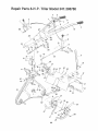
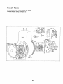
Repair Parts 8=HoPoTilBer Moden 247o298780
i
42
41
22
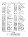
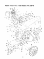
Re#a![. parts 8-H.P, Tiler ModeU 247,298280
REF.
NO.
PART
NO_
-_
7! 0°022?
2
746-0304
3
4
747-0255
7t0-0136
7
749-0268
720-0180
712-0t07
I
10
11
t2
t3
!4
15
4830
04831
749-0269
720-0183
04892
714-,0t 45
'736-0t01
732-0!93
16
!7
18
19
712-0214
04833
710-0344
7t4-0!15
20
2t
22
23
24
25
26
27
28
29
30
31
32
34
732-0306
747-0256
747-0252
04804
'710-,0623
736.0169
710-0623
736,.0t;69
736-0 ! 0 !
7t2-0;t 30
04861
04673
04683
711-0599
35
36
37
742-0175
710-.019t
04857
38
39
40
41
42
73640169
712-0241
714-0145
742-0174
04855
46
47
736-0I 69
712-0798
fEFo
DESCRIPIION
Hex Wash, Hd Tap Scr0 #8
x 50" Lg,*
Throttle Control Ass'y.
Comp.
t4andte Lock. Rod
Hex Scr. V4-20 x 1.75" Lg.*
Hand!e--R. H.
Grip
Hex Cent L.Nut I/4-2(:}Thd.
Clufch Grip
Handle Panel Ass'y.
Handle .... L H
Ball Knob
Clutch Handle Ass'y
Hair Pin Cotter
FI.Wash.
CompressiOn Spring .88
O,D x,81 Lg.
Hex Nut 3/8-24 Thd *
Depth Bar
Hex Scr, 3/8:16 x 1.50" Lg,.*
Cotter Pin 1 t8" Dia x!,00"
Lg *
Compression
Spring.
Depth Bar Adjustment
Pin
Hinge Rod
Wine Shield Hinge Flap Ass'y,
Hex Wash° Hd, Self Tap Scr.
L-Wash. 3t8" Scr,*
Hex Wash. Hd, Self Yap Scro
L-Wash. 3/8" Scr. *
FFWash.
Hex Ins.. L-Nut 318-16 "fhd.
Drag Bar Ass'y,,
Inner Wine Adapter Ass'y
Outer Wine Adapter Ass'y.
Clevis Pin 3!8" Dia. x 1.75"
Eg_
48t 04820
49 I 712-0267
501 736.0,1.t 9
TIne..-.L,.H.
Hex Scr, 3f8-24 x ! ,25" Lg, _
Outer Ttne Ass'y. Comp,._
L.H.
L,-,Wash. 318" Scr. *
Hex Nut 318-24 Thd."
Hair Pin Cotter
Tine.-,R..H_
Inner Wine Ass'y. Comp,-L, H.,
L-Wash° 3t8" Scr. *
Hex Nut 318.,t6 Thd. _
Chain Case Ass'y. Comp.
Hex Nut 51t6-!8 Thd *
L_WaBh. 5t!6!'
Sor. *
L
"Standard
Hardware
Items-May
Be Purchased
REF. NO.
42
Not Shown
__3!___............
PART
DESCRIPTION
Handle Posjttoner Ass'y,
L-Wa,sll, 318" Scr,*
Hex Ins, LoNut 3/.8-24 Thd,
COtter Pin 1 t8" Dia. x ,75"
Lg, T
FI-Wash .630 I.D. x 1.0" O,D.
55 736-0290
x ,063
L-Wash, 5t 16" Scr. +
56 736_01t9
S hid. Scr, .50 x .25
57 738- 0258
Bell, Wash.
58 736-0105
59 7! 0-0623
He× Wash. Hd, Self Tap Scr.
Control Brkt.
60 0484t
Hex Wash. Hd, Self Tap Scr.
61 710-0601
62 710:-02!6
[-flex Scr. 3t8-16 x .75" Lg, *
(]otter Pin t t8" Dia. x 1.00"
63 714-01 t5
Lg,*
Ttne Shield Ass'y
6.4 04796
Hexlns
L-NuI3t8-16Thd
65 712-0130
L,.Wash 3t8" Scr,*
66 736-0I 69
Cotter Pin 1 f8" Dia,, x t ,00"
67 714-0115
Lg.*
68 04806
Pivot Horn Ass'y.
Gear Sl_ift Rod
69 747-0278
Rod End 3t8_24 Thd
70 723o0156
71 04812
Pivot Brkt. Ass'y,,
Hex ins, [,.-Nut 518-16 Thd.
72 7t 2o0221
73 7t I _0663
Locking Pin
74 732.,0132
Compression
Spring
Cotter Pin t !8" Dia, x ,75"
75 7t4-0474
Lg *
Bell. Wash_ °505 IoD, x 1_00"
t6 736.,_0253
O.D,
Lower Handle Control Rod
_7 747-0254
Fl.,Wash, 50" f.D. x 1.00
_8 736-0i92
O,D. x ,090
Hex Nut 5/16_18 Thd,"
_0 712-0158
31 748-0516
Pivot Handle Brg
F_ivot Handle Link
3'2 0.4819
33 736-0289
Bushing Wash.
34 738-0148
Shld. Scr, .500" Dia. x _660
Hex Nut 5t16-t8 Thd."
851 712-0267
L-Wash, 5/16" Scr, *
861 736-0119
Cam Bolt 5t16-18 x 1.75"
871 710-0458
Lgo*
/
Handle Mtg. Brkt Ass'y.
88 t 047.92
Conduit and Wire
89 i46-0305
90 7I 0-0152
Hex Scr. 3t8..24 x 1.00" Lg,
91 I 712-0181
Hex Top L-Nut 31846 Thd,
Sleeve Brg .50 I.D, x .62
921 748-0150
O,D. x 1.12 Lg.
l
Hex Jam Nut 3t8-24 Thdo
93 I "712-0711
F,errule
94 I 711-0198
Owner's Manual
t j 770°7764
Warranty Decal
.......
.t_L..7_TZ-,Bsj
7
51
52
53
54
04850
736.O! 69
71 2-01t6
'714.-0474
lNot
Locally.
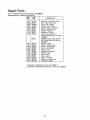
WINE CHART
DESCRIPTION
Inner Wine Ass'y,, Comp. _-L. H.
Outer Wine Ass'y, Comp._RoH.
Outer Tine Ass'_., C_,
_L. H.
23
PART NO,
04854
04855
04856
04857
illustrated
6
3O
23
64
i
.....
41
....14
¢5
.48
4_6
"-...,
5O
53
24
24
2/5 2:27
28/
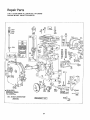
R__ep ,.!LParts
8°H.P. TiWgerMode 247
_EF
NO
I
2
3
4
tl
12
13
14
t5
t6
17
t8
19
PART
DESCRIPTION
NO,
752-06! 4
756-0297
736-,0159
736-0119
7101.0627
712.-0! 30
736_0169
756-0225
04836
736-0329
710-0230
736-0227
71o-o191
o.4i9o
710-0599
717-0383
71 T-0382
04859
04858
72"t-0162
719-0237
7'19-.0238
74t -0862
732-0863
720.0143
7117-0265
7t 5-0139
05034
741-0!55 !
710-0650l
Y14_0122i
738..0372
710-0502
736-0t69
7tO-0623
42j
04820
*Standard
Hardware
ltems_May
#ESCP.IPT!ON
NO,,
Engine B. & S. 190402
1_43
- 7!2-0138
44 7t2-0116
Type 0944,-01
45 710-03217
Belt Cover Support Ass'y.
46 710-0191
internal U-Wash. 1/_,,Scr*
47 734,"0807
Hex Scr., t/2_20 x .75" Lg.*
734-0806
"V"-Beit 518" x 27,0" Lg.
Variable Speed Ass'y,
04848
"V"-Belt 5t8" x 52.0" Lg,
734-0808
Spacer 6371_D, x.780
D x
734.,0456
1 44" Lg.
_8 7!0-0t52
Input Pulley _-Transmission
_9 710-0359
Fl-Wash. 5t16" Scr.*
_0 04860
U;Washo 5/t6" Scr,*
736-Ot79
H
Flex L-Scr., 5/16_24 x .75" Lg,
_2 736-0921
Hex Ins. L-Nut 318-16 Thd,
)3 712-0384
L-Wash,, 3f8" Sor.*
54 723.-0340
Ft-.ldler 2.75" Din.
35 712-02t 4
Friction Disc
_6 71 2-0267
L-Wash-, 1A', Scr, *
57 736-01 ! 9
Fiex Scr. 1/,_28 x o50" Lg,
FI-Wash. ,.375 I D.'x 1 ,,50
58 04844
O,D, x ,035
S9 732-OI53
Hex Scr, 3t8-24 x ! _25" Lg,*
60 04864
Belt Cover
6t
712.-0138
Hex Wash., Hd. Self Tap Sc_o
62 712-0130
63 04837
Clutch Dog Driver
Cfutch Dog
64 736-0237
Shift Yoke Ass'yo_,L.H,
65 714-0474
Shift Yoke Ass'y°_R.
H_
(Not Shown)
Gasket-r, Shift Housing
60 738_0380
67 710_0106
Shift Houslng--L,H,
Shift Housfng--R,
H.
6_ 7t 2-0324
6c_ 04841
(Not Shown)
Detent Ball
70 710-0623
Compresstor_ Spring
71 710_0621
72 736L01 .t 9
Grip
73 750-0381
Engagement Lever
Headed Spiral Pin 3/16 x
74 05080
13/t6"
Lg.
Bearing Housing
75 756..0296
Bal! Bearing
76 710-0599
Hex Tap Ttte 51!6..18 x .87"
77 04840
78 736-0! 73
Lg.
Bell, Wash .345 I.Do x .88
79 712-0117
O,D
80 736-0173
81 7! 0-0t 95
Sq, Key 3116 x .75" Lg,
82 7t 0-0599
Shoulder Spacer
Hex Self Tap Scr. 318-16 x
83 714,.0! 18
1.25" Lg.
84 710-0380
L-Wash, 3/8" Scr,*
86 750-0382
!04863
He× SF Tap Scr, 3f8-16 x ,75"
86 751-0233
Lg.
Transmission
Ass'y Comp.
749-0275
048! 5
736-0114
7t0.-0121
754-.0220
717-0343
754 _0221
750-0387
298780
Be Purchased
Hex ins. L_Nut 3t8-24 Thd.
Hex Scr. 3f8-'16'x 1,75" Lgo
Hex Scr. 3t8L24 x l .25" L_,,
Wheel Ass'y., Comp.._L.H.
Wlleel Ass'y. Comp..-,R
H,
(Not Sllown)
Rim Only
]'ire Only t6 x 4.80_8
Tube Only 16 × 4°80-8
He× Scro 3t8-24 x 100" Lg.*
Cam Bolt V2-,I3 x 6,00" Lg.
Weigh[ Mtgo Brkt.
Flat Washer
L-Wash.. V2" Scr. *
Hex Cent, L-Nut V2,-13 Thd,
We.ight
Hex Cent. L.-Nut 3/8-24 Thd. *
Flex Nut 5t16.-i8 Thd,*
L-Wash. 5f16" Scr,,*
Frame Ass'y,
Extension Spring
Idler Arm Ass'y.
Hex Gent, L-Nut _/_-28 Thd,.
Hex Ins, L,.Nut 3t8-16 Thd..
Variable Speed Brkt. Ass'y,
FI-Wash..686
I.D, x 1.25
O.D.
Cotter Pin t18" Din. x .75"
Lg_*
Shld,, Sor. 1/_,, Din. x .25" Lg.
Hex Scr, V4-20 x 1.25" Lg*
Hex Ins, L-Nut 1/4_.20Thd.
Control Br.kt.
Hex Wash. H_fo Self Tap. Scr,,
Hex Scr. 5/16-18 x .50" Lg,,*
L_Wash. 5t16" Scr.'
Spaoe'r,l.25"
O,D, x 13 Ga,
x ,40
'
Friction Wheel Ass'y,
Eilgine.Pdtley
Ass'y,
Hex Wash, Hd, Self Tap Scr,
Belt cover Extension Ass'y,
FL-Wa_h, %"' Scr,
Nex.Gent, L-Nut 1/4-28 lhdo
EI-Wash, 1/4;' Scr,
Hex Scr, _/;_,-28x ,62" Lg, *
Hex Wash Hdo Self Tap Scr.
Sq, Key V4" x 1,50" Lg,*
Hex Scro 5/t6-18 x 1 o75" L.g, *
Spacer
Rear Belt Cover Support Brkt,
Muffler Deflector
Vibration Damper
Locally,
TILLER ACCESSORIES
V-Bar Cultivating
Kit
V-Bar Frame
4-pt. Cultivating
Tines
Hiller/Furrower
Depth Gauge Wheels
6-Tang Universal Cult,
Cultivating
Sh letds
32" Leveling f Snow-Blade
Wheel Weights
Wheel Weights F t Leveling
Front Hitch Mount
Tire Chains
25
Snow-Blade
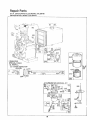
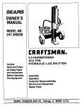
Repair Parts
8-H,P. CHAIN DRIVE TILLER MODEL 247,298780
ENGINE MODEL 190402 TYPE 0944-01
_-I_,_ _
304
363
•
75
26
334_,""' ....
RepaBr Parts
8-H.P, CHAIN DRIVE TILLER MODEL 247,298780
ENGINE MODEL 190402 TYPE 0944.,01
25
26
"F8_3
....................
iS"
209
_EQU IRE,S
SPECIAL TOOL,S
\
616
Z20
2!9
356
g_'E"
#EPAIRIN_T#UCTIO#
AAAWUA8
27
Repair Parts
8-H.P_ CHAIN DRIVE TILLER MODEL 247.298780
ENGINE MODEL 190402 TYPE 0944-01
729
TO INSTALL
SE_R_',P,4/R
iHS,zRUCZiON
,4NU,4_ _ _ 270
_i:_
.......
_iL_
_ _-
...........................................................
64.3:-__..
445-_
121CARBURETOR
OVERHAUL
KIT
=.=,
t66
_o_,_
,tz;,.=_a
_
104 i.
_oo®
""--,_,
_119
_
_ .......yO-@
/
tB
28
3O5
Repair Parts
8-H_Po CHA!N DRIVE TILLER MODEL 247.298780
ENGINE MODEL 1.90402 TYPE 0944-0!
NO,
295962
Note:
294606
21 I7_'8
"270430
39032"t
'27803
93536
Note:
DF_SCRtPTtON
[JESCRIPTION
Cyiinder Assembly
B.ushlng--Cylinder
Requires special tools for
instaflati.on
32. 92659
33 390419
34 261055
35 65906
36 26828
40 221596
41 292260
42 93630
Seal--Oil
He'ad_C_,linder
Gasket--Cylinder
Hd
Breather Ass'y
Gasket.-.Vafve Cover
Screw.-:_ Sere
93535 ScrewU-Sem Used to
mount Output Bracket
:.
Ri_tainer on type No. 0800,
Tube_ Br(_ather
3907.69 Tube--Breather Used
ontype Nos, 0638, 0694, 0803,
0810, 08I 4, 0825.
"27750
Gasket--Crankcase
Cover.--1164" thick
*27876
Gasket-_C, rankcase Cover-,005" thick
*27877
Gasket _-Crankcase Cover-.
.009" thick
13 93113
Screw-..,Cytinder
Head
(2:-5f16 _' long)
14 93211
Screw--,Cytinder
Head
(2-9/16" long)
15 91084
Plug--Oil
Drain
16 261149
Crankshaft
18 391010
CoverAssembly-.Crankdase
19 295964
B ushing--.Crankcase
Co.ver
Note:
Requires special tootsfor
instatlatlonL
20 298453
Seal--Oil
21 66768
Plug : O!1 Filler
22 93585
Screw---Crankcase
23 298260
FI ywheet.':- Mag nero
24 61760
Key,.--FlYwheel
25 391673
Piston AS'S'y. L-Std,
391674
Piston Ass'y,_,010"
O,S,
391675
Piston Ass'y _,020" O.S_
391676
Pis:ton Ass"y, _.030" O. S
MODEL 190400 SE'RIE_; PISTON RING SETS;
Note:
i=or. Cl_r'orneRing se{_-Std.
Si.ze--order Noo 299743°
26 3,9.1669
Ring Set-*Piiston,--Std
391670
RiOg Set--Piston .... 010" O.,S,
391671
Rlng Set,;--.,Piston--.020" O,S.
391672
Ring' Set--Piston--.030"
O_So
27 68546'
Lock--Pfston
Pin
28 295840
Pin As,_'y.._Piston.--Std,
295841
Piln Ass'y,--Piston--.
45 260933
46 210728
50 211812
5I '270684
Note:
0878..
:
,005" O:.s,
29
30
390401
Note:
222,1t3
Lock .--Connecting
Rod Screw
Screw--Con necting Rod
Valve.-_ Exhaust
Valve_fnlake
Spring--tn take Valve
Spring,- Exhaust Valve
Retai ner--t n take Valve
Rotocoit-- Exhaust Valve
Retainer_ Exl_aust Valve
Rotbcoit (2)
Tappet--Valve
Gear .-_-Gam
Elbow _ Intake
Gasket.--Carb
Mtg.
270824 Gasket--,-Oarb, Mtg,
Used on. type Nos, 0800, 0877,
Rod Ass'y, :--Connectfng
FoP Con,necgr_g Rod wi.th
,020" dn,dersfze Crankptn
Bo're--O'rdei' No. 390773.
Dlpper_Oonnecttng
Rod
'Included in Gasket Set--Part No, 299577,
•
1"Included in Carburetor Overhaul Kit_Part
No, 295938::
29
52
53
54
'27828
93128
93208
55
56
295272
295871
Note:
57
58
294303
66884
59
60
63
64
65
230228
66728
260414
230543
93067
66
67
298198
211383
68
69
63T?0
66718
70
298799
71 221653
73 221796
74 93042
75 220865
76
_8238
81A222263
90 390323
91
390404
92 3905Q3
93 231-08
94 "292681
Gasket-- Intake Elbow Mtg,.
Screw,-Carburetor
Mtgo Sam
Screw_lntake
Elbow Mtg,
Sere
Hous.ing--Rewind
Starter
Pultey_RewJnd
Starter
Includes 63" rope; if longer
rope is required, order rope
No..66894 and cut tc_required
length
Spring-,--Rewind
Starter
Rope_ Rewind StaFter _63"
tdng
Pin ,-,Starter Grip
GripeS:tarter
Rope
Spring-- Ratchet
Adapter_-Ratchet
Sl_ring
Screw-.Stamped
Steel
Ele_Jind Star_er HousJhg Mtg,
Sam
Clutch Ass'y.,--,Rewind
Starter
Housing_ Rewind Starter
Clutch
Ball--Clutch
Washer.-- Starter Clutch.
Thrust
Ratchet.-. Rewind Starter
ClutCh
Washer--Retainer
S.creen-,, Rewind Starter
Screw--Sere
Wasber--Spring
Washer--Ratchet
Sealtag
Lpck-,Muffler
Mtg, Screw
Carb..ureto[ Ass'y, (Manual
Choke)
Body Ass'y, _Upper
Carburetor
Body_Upper
Carb,
Bushlhg--Throttje
Shaft
Valve Ass'y._.Carb,
Idle
Repair Parts
8-H,.P. CHAIN DRIVE TILLER MODEL 247.298780
ENGINE MODEL 190402 TYPE 0944-01
NOJ
NO.
_'
93499
i
96
97
98
62940
298826
91920
99
100
1O1
f02
103
!04
! 05
107
26157
61967
93043
f279!8
99333
t230896
299096
390403
I08 62872
109 391987
t 10 62899
tll
26155
112 23123
t .13 390395
1t4 68667
! 18
,}9525
119 90746
t 20
92290
t21 298938
164 91628
165 93453
166. 392105
180 290816
181 392301
I82
221935
183 291367
184 91257
185
186
187
188
189
90970
67218
39t498
93535
90366
200
20t
209
219
221760
260872
261126
391737
Note:
220
222
227
229
230
240
241
242
221551
390670
39,1965
220680
222450
295984
296005
295913
DESCRIPTION
Sorew-=,Throttle
arid Choke
Valve Mtg. Sere
Valve--Throttle
Shaft and Lever--Throttle
Screw--Machine,
FH. Hd.-8-32 x 5f8"
Spring--Throttle
Adjustment
S[op--.Throttle
Pin_Throttte
Stop
Gasket--Carburetor
Body
Float--Carburetor
Pih--Ftoat
Hinge
Valve_Fuet
Inlet
Body Ass'y,_Lower
Carburetor
Valve_Choke
Shaft and Lever--Choke
Washer--Choke
Lever
Spring--Choke
Lever
Screw--Choke
Lever
Nozzle--Carburetor
Gasket_ Nozzle
Valve...--Needle
Screw.-Machtne,
Fil. Hd,._
t0_32 x 518"
Washer_ Loci{--,
NO. 10 x 1/16" x 3/64"
Carburetor Overhau! Kit
Pipe Ass'y,,_Air
Cleaner
Nub--Wtng
Stud--.Air
Cleaner Strap
Tank Ass'y..,--Fuel
(4 quart)
Cap_Fue!
Tank
Bracket--.Fuel
Tank
Strap Ass'y.Fuel Tank
Screw.--Machine,
Ffl, Hdo_
V4-20 x 1 _./2
_'
Nut--Square.-V4-20
Connector--Fuel
Pipe
Pipe--Fuel
(Flexible)
Screw_Sem
Washer-_Lock,
51t6 x t/8
x t f16"
Gulde_Air
Link--Governoi
Spring--Governor
Gear--,-Governor (Used afte_
Code No, 75060511)
297656 Gear--Governor
(Used
before Code No. 75060611 )
Washer-_-Thrust
PIate--Gov.. Control
Lever Ass'y, _Gdvernor
Washer
Washer--Governor
E{lter Ass'y,._Fuel
Cover Ass'y.--Fue[
Filter
Valve_Fuet
Shut-Off
|EF._
PART
_o.
NO,
243 22547
244 230318
245 "68477
246 298683
247 99665
265 221535
268 65616
Note:
269
26633
Note:
270
271
278
300J
304
305
306
307
63426
290568
22358
3913t3
299853
93158
221898
93'163
308
333
334
337
340
341
221901
298968
93381
293918
26018
93381
342
345
346
356
357
358
363
65704
222t17
93705
299500
91540
299577
1_j165
372
373
375
220477
92987
294628
Note:
445
516
523
524
525
535
No. 299,577,
"Included in Gasket Set--Part
No. 295938.
1"Included inCarburetor Overh'au! Kit_Part
3O
390930
260374
,390969
68838
390970
270782
DESCRIPTION
Screen_Fuel
Filter
Conneotor_Fuel
Pipe
Gasket_Fuel
Filter Bowl
Bowi-- Fuet Filter
Yoke--Fuel
Filter
Clamp--Casing
Caslng_Control
Wtre_72"
tong
ff longer Casing is required,
specify l ehgth In inches;
f
shorter wire is needed, order
No. 656_6 and cut to required
length,
Wire.-Control--,78"
long
if longer wire is requh"ed,
specify }ength in inches; if
shorter wire is needed, o_der
No, 26633 and cut to required
(ength_
Lockriut--Control
Wire Casing
Lever Ass'y.,--Control
Wash er_ Flat
Muffler--Exhaust
Housings-Blower
Screw.-.Sem
Shield ---Cylinder
Screw--Cylinder
Shield Mtg_
Sem
Cover--Cylinder
Head
Armature Ass'y,
Screw--Armature
Mlg.. Sem
Plug_Spark
(Resistor Type)
Spring-- Breaker Arm
Screw--Breaker
Arm Mtg.
Sere
plunger-, Breaker Point
Cover--Breaker
Point
.Screw--Sere
Wire--Ground
Key--Pulley
Ga#ket Set
P011er_-.Flywheef (Optional
Accessory)
Clamp_Gondenser
NutTHex
Breaker" Points and Condenser
Set
299061 Ignition Kit Includes;
294628: Polht Set
65704 plunger
6176(} Key--Flywheel
Cartddge.---.Air Cleaner
Spring--Connector
Cap and Dipstick--Oil
Filler
Seal--.Fl.tler Tube
Tube--Oi!
Filler
Element--Air
Cleaner
Cleaner AS_SS'y_c:_A'_
r ............
Repair Parts
8-H,P. CHAIN DRIVE TbLLER MODEL 24.7.298780
ENGINE MODEL 190402 TYPE 0944_O1 '
PART
REF.
NO.
NO,
552
562
592
601
608
613
614
615
616
231056
92613
231082
93053'
295001
93704
93306
93307
23:1057
Note:
621
635
642
643
657
676
725
729
836
842
843
297472
66538
222271
222272
93496
222261
221885
221907
93559
270933
280149
221798
*included
"[Included
DESCRIPTION
Bushing--Governor
Crank
Bolt--Governor
Lever
Nut.--,-Hex,--10-24
ClampZ-Fuel
pipe
starfe_; Ass'y,--Rewind
Screw.- Muffler Mtg.
Cotter--Hair
Pin
Retainer--E-F(ing
Crank-., Governor, (1,¢"
diameter) Used after Code No,.
75060511.
230842 Crank,--Coy.
(3t 16"
alia,,) Used before Code No,
75060611.
Switch-*-Stop
Elbow-- Spark Plug
Cover_AIr
Cleaner
Cup.-,Air Cleaner
Screw_Sem
Deflebter.-- Exhaust
Shield_Heat
Clip_Wlre
Screw--Sere
Seal_"O"
Ring
Sleeve--Choke
Lever
in Gasket Set---Part No. 299577,
in Carburetor Overhaul Klt_Part
No,, 295938.
31
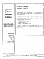
HOW TO ORDER
REPAaR PARTS
f'he Model
Number
will
chassis
Always
rnent]dn
repair parts for your tiller
be found, stamped
the Mode! Number
Ati parts listed here_n may be ordered through SEARS ROEBUCK
or SIMPSON SEARS LIMITED RETAIL or CATALOG STORE,
m #U l
WHEN
ORDERING
REPAIR
PARTS,
ALWAYS
INFORMATION
AS SHOWN
IN THIS LIST,
ODEL NO.
247.298780
ROEBUCK
PART
NO.. 77_7764
on a plate
atlached
to lhe
when requesting
service
o_
1
The PART
2
The
GIVE
THE
AND CO
FOLLOWING
NUMBER
MODEL
NUMBER
247,298780
3 The PART DESCRIPTION
4, The NAME OF MERCHANDISE--Tiller
If the parts you need
electronically
t,ransmitied
expedited handlirig
AND
(30.,
are not stocked
locally,
your order Wilt be
to a Sears Repair Parts Distribution
Center for
Cht_J1L
(}0684
U,_A.
PRINTED
_t"4U_S,A_