1
ZETRON
Models 1708 and 1716
Remote Terminal Units
Installation and Operation Manual
Part No. 025-9209J
Copyright © 2004 by Zetron, Inc.
All Rights Reserved
Statements
WARRANTY
Zetron’s warranty is published in the current Zetron United States Price Book.
LIMITATION OF LIABILITY
Zetron makes no representation with respect to the contents of this document and/or the
contents, performance, and function of any accompanying software and specifically
disclaims any warranties, expressed or implied, as to merchantability, fitness for purpose
sold, description, or quality.
Further, Zetron reserves the right to revise this document or the accompanying software and
to make changes in it from time to time without obligation to notify any person or
organization of such revisions or changes.
This document and any accompanying software are provided “as is.” Zetron shall not under
any circumstances be responsible for any indirect, special, incidental, or consequential
damages or losses to the buyer or any third party arising out of or connected with the buyer’s
purchase and use of Zetron’s products or services.
COPYRIGHT
This publication is protected by copyright by Zetron, Inc. and all rights are reserved
worldwide. This publication may not, in whole or in part, be copied, photocopied,
reproduced, translated, or reduced to any electronic medium or machine-readable form
without prior written consent from Zetron, Inc.
The software in this product is protected by copyright by Zetron, Inc. and remains the
property of Zetron, Inc. Reproduction, duplication, or disclosure is not permitted without
prior written consent of Zetron, Inc.
TRADEMARKS
Zetron is a registered trademark of Zetron, Inc.
All other product names in this document are trademarks or registered trademarks of their
respective owners.
025-9209
iii
Statements
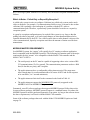
FEDERAL COMMUNICATIONS COMMISSION (FCC) REGULATIONS
This equipment has been tested and found to comply with the limits for a Class A digital
device, pursuant to Part 15 of the FCC Rules. These limits are designed to provide reasonable
protection against harmful interference when the equipment is operated in a commercial
environment. This equipment generates, uses, and can radiate radio frequency energy and, if
not installed and used in accordance with the instruction manual, may cause harmful
interference to radio communications. Operation of this equipment in a residential area is
likely to cause harmful interference in which case the user will be required to correct the
interference at his or her own expense.
Changes or modifications not expressly approved by the manager of Zetron’s compliance
department can void the FCC authorization to operate this equipment.
Repair work on this device must be done by Zetron, Inc. or a Zetron authorized repair station.
iv
025-9209
Statements
025-9209
v
Statements
vi
025-9209
Contents
WARRANTY ......................................................................................................iii
LIMITATION OF LIABILITY ...........................................................................iii
COPYRIGHT.......................................................................................................iii
TRADEMARKS ..................................................................................................iii
FEDERAL COMMUNICATIONS COMMISSION (FCC) REGULATIONS...iv
INTRODUCTION
GENERAL...........................................................................................................1
SYSTEM DESCRIPTION...................................................................................2
MODBUS SYSTEM............................................................................................2
CONNECTIONS .................................................................................................3
SPECIFICATIONS
PHYSICAL SPECIFICATIONS .........................................................................5
RS-232 INTERFACE ..........................................................................................5
RADIO INTERFACE..........................................................................................5
Radio Modem Specifications...................................................................5
Signal Integrity ........................................................................................6
I/O SPECIFICATIONS .......................................................................................6
External Inputs .........................................................................................6
External Outputs ......................................................................................6
OPERATION
GENERAL OPERATION ...................................................................................7
ADDRESSING THE RTU ..................................................................................8
CONFIGURATION.............................................................................................9
Accessing the RTU Program Mode .........................................................9
MAIN MENU ......................................................................................................10
Prekey Time .............................................................................................10
Channel Busy Detect ...............................................................................11
Channel Busy Timeout ............................................................................11
Transceiver Type .....................................................................................11
Address Extension ...................................................................................11
Controller Address ...................................................................................11
Group Call Address .................................................................................11
Factory Defaults.......................................................................................12
FAIL SAFE SETUP.............................................................................................12
Communication Failure Enable ...............................................................12
Channel Use Limits..................................................................................13
Enable/Disable Exception Reports ..........................................................13
STORE AND FORWARD ..................................................................................13
Slot No. ....................................................................................................14
Source Address ........................................................................................14
Destination Address .................................................................................14
Replacement Source Address ..................................................................14
025-9209
vii
Contents
Replacement Destination Address ...........................................................14
Next slot ...................................................................................................14
Example ...................................................................................................14
DIGITAL INPUT DEFINITION.........................................................................15
Enable Input .............................................................................................15
Disable Input............................................................................................16
N/O Input .................................................................................................16
N/C Input .................................................................................................16
Status Input ..............................................................................................16
Debounce Time........................................................................................16
Next Input ................................................................................................16
DIGITAL OUTPUT DEFINITION.....................................................................17
Latched Mode ..........................................................................................17
Momentary Mode.....................................................................................17
Output On.................................................................................................17
Force Output Off......................................................................................17
Next Output..............................................................................................17
ANALOG INPUT DEFINITION ........................................................................18
Enable Input .............................................................................................18
Disable Input............................................................................................18
High Threshold ........................................................................................18
Low Threshold .........................................................................................18
High Reset................................................................................................19
Low Reset ................................................................................................19
Accumulator Sampling Rate ....................................................................19
% Change Alert........................................................................................19
% Change Debounce................................................................................19
Next Input ................................................................................................19
SYSTEM OPERATIONAL LIMITS ..................................................................20
Inputs .......................................................................................................20
Outputs.....................................................................................................20
Power .......................................................................................................21
Radio Connections and Associated Problems..........................................21
Critical System Failures Summary ..........................................................22
MODBUS SYSTEM SET UP
MODBUS OPTION.............................................................................................23
COMMUNICATIONS ........................................................................................24
Polled-Only System .................................................................................24
Report-By-Exception System ..................................................................24
Which Is Better - Polled-Only or Report-By-Exception?........................25
MODBUS MASTER REQUIREMENTS ...........................................................25
CONFIGURING THE 1700 CONTROLLER.....................................................26
MODBUS Menu ......................................................................................26
Polled-Only Configuration ......................................................................26
Report-By-Exception Configuration........................................................27
viii
025-9209
Contents
RS-232 Watchdog Configuration ............................................................28
CONFIGURING THE RTUs...............................................................................28
Assign Addresses .....................................................................................28
MODBUS Version of the RTU Menu .....................................................29
CONFIGURING THE MASTER PC (OR PLC).................................................29
BASIC MODBUS I/O ADDRESSING ...............................................................30
USING ACCUMULATORS AND COUNTERS ...............................................31
SOFTWARE PRODUCTS FOR THE MODBUS PROTOCOL ........................36
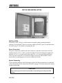
SET UP AND INSTALLATION
INSTALLATION ................................................................................................37
Power Connection....................................................................................37
System Grounding ...................................................................................37
Radio Connection ....................................................................................38
Step 1. Cable Connection.........................................................................38
Step 2. Carrier Detect and Push to Talk Settings.....................................38
Step 3. Transmit and Receive Audio Adjustment....................................39
MODEL 1708 JUMPERS AND I/O....................................................................40
Model 1708 Jumper Settings ...................................................................40
Model 1708 I/O Connections...................................................................41
MODEL 1716 JUMPERS AND I/O....................................................................42
Model 1716 Jumper Settings ...................................................................42
Model 1716 I/O CONNECTIONS...........................................................43
CONNECTION OF LOCAL RTU TO MODEL 1700 CONTROLLER ............44
50-PIN INDUSTRIAL I/O BOARD CONNECTOR ..........................................45
THEORY OF OPERATION
BASIC FUNCTIONAL DESCRIPTION ............................................................47
FUNCTIONAL BLOCK DIAGRAM .................................................................47
TROUBLESHOOTING GUIDE
OVERVIEW ........................................................................................................49
REPAIR
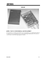
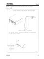
MODEL 1708/1716 COVER REMOVAL AND REPLACEMENT ..................51
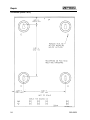
MODEL 1700 SERIES ENCLOSURE OUTLINE (024-0057B) .......................52
MODEL 1700 SERIES ENCLOSURE INSTRUCTIONS (024-0056D)............53
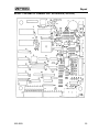
MODEL 1708 REMOTE TERMINAL UNIT SILKSCREEN (702-9439F) ......55
MODEL 1716 REMOTE TERMINAL UNIT SILKSCREEN (702-9440F) ......56
APPENDIX A
COMMUNICATING OVER TWO-WIRE BALANCED LINE (600Ω) ...........57
025-9209
ix
Contents
APPENDIX B
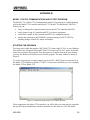
MODEL 1730/1732 COMMUNICATIONS AND I/O TEST PROGRAM........59
STARTING THE PROGRAM ............................................................................59
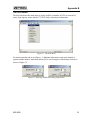
SETTING OPTIONS ...........................................................................................60
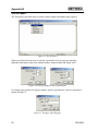
THE POLL MENU ..............................................................................................61
THE SET MENU.................................................................................................62
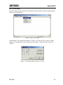
THE CLEAR MENU...........................................................................................63
GLOSSARY
INDEX
x
025-9209
INTRODUCTION
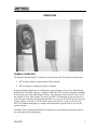
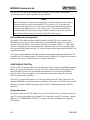
GENERAL
A Model 1708 or 1716 Remote Terminal Unit (RTU) is one part of a wireless SCADAi
telemetry system. A SCADA system typically consists of a PC with software connected to a
Controller and one or more RTUs at multiple distant locations. The Controller and RTU are
both microprocessor controlled and, along with the user’s radio link, make up the
communications network necessary for monitoring and controlling equipment at remote sites.
The Controller is typically located at a central office and can address up to 65,535 RTUs
located at various remote sites. Using the Controller and the RTUs, the user at the central
office can control equipment or retrieve information from the remote sites.
The size of a system is dependent on airtime available and the total transmissions required.
To determine the maximum number of RTUs your system will support, call Zetron at (425)820-6363.
The RTU interfaces directly to a wide variety of two-way radios, either conventional or
trunking. The RTU is designed to connect to remote sensing devices that can provide dry
contact closure to ground, TTL level voltage changes or 0 to 5 volts and 4 to 20 mA for
analog measurement.
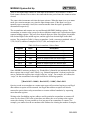
Table 1 lists the I/O capability of the Models 1708 and 1716 RTUs and the Model 1700
Controller.
i
SCADA = Supervisory Control and Data Acquisition. A general term for an industrial measurement, data
gathering, and control system.
025-9209
1
Introduction
Table 1. Digital and Analog I/O Capability
I/O
1708
1716
1700
Digital In
Digital Out
Analog In
Analog Out
8
8
4
0
16
16
8
4
0
4
0
0
The RTU is initialized through the RS-232 port, which allows the user to customize the
parameters for each RTU to best fit the application.
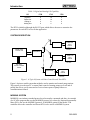
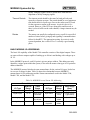
SYSTEM DESCRIPTION
Transceiver
Model 1700
Control Unit
1708/1716
RTU
Unit #1
I/O Lines
Transceiver
Transceiver
1708/1716
RTU
Unit #2
I/O Lines
PC, CRT,
Printer or Status
Panel
Transceiver
1708/1716
RTU
Unit #9
I/O Lines
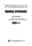
Figure 1. A Typical System with One Controller and Nine RTUs
Figure 1 depicts a model system that might be used to monitor and control pump stations.
This system gives the user PC or status panel control of turning pumps on or off and of
polling the sites to verify status and to receive alarm reports of pump failures or
communications failures.
MODBUS SYSTEM
MODBUS is an industry-standard protocol used to transfer commands and data. An example
of a SCADA program that uses the MODBUS protocol is Lookout (by National Instruments).
Many PLCs also use the MODBUS protocol. A MODBUS option for the Model 1700
controller allows the controller and Zetron RTUs to be used in a MODBUS system.
2
025-9209
Introduction
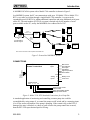
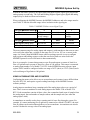
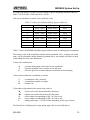
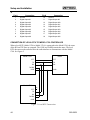
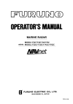
A MODBUS SCADA system with a Model 1700 controller is shown in Figure 2.
In a MODBUS system, the PC can communicate with up to 150 Model 1708 or Model 1716
RTUs over radio or wireline through a single Model 1700 controller. A system can be
expanded beyond 150 RTUs by adding additional controllers and using additional serial ports
on the PC. The total number of RTUs in a system is limited only by the number of serial
ports available on the PC, and by the MODBUS slave address limit of 247.
M1708/
M1716
RF
RS232
M1700 with
MODBUS Protocol
MODBUS
option
Modbus PLC
- or PC with Modbus
SCADA Program
M1708/
M1716
RF
RS232
MODBUS
Protocol
RF
M1708/1716
with MODBUS
RF - Store & Forward
option
M1708/
M1716
M1708/
M1716
Note: all RF connections could be replaced with leased lines
Figure 2. Generalized MODBUS System
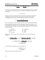
CONNECTIONS
Radio
Connections
Model 1716
Remote Terminal Unit
Digital
Inputs
#1
•
•
•
Main Power
Flow Detector
Door Open
High Water
High Temperature
Panic Button
#16
Analog
Inputs
Digital Outputs
#16 • • • #1
#1
•
•
•
#8
Battery Level
Tank Level
Pump Control On/Off
Alarm On/Off
Panic Acknowledge On/Off
Back Up Power On/Off
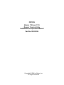
Figure 3. Model 1716 RTU Standard Connections for a Pump Site
A standard application of monitoring and controlling a remote pump site could be
accomplished by using output #1 to control the pumps on/off switch and by connecting input
#1 to a flow meter to determine if the pump is pumping. If the control relay on the RTU is
damaged, the pipe is blocked, or a short or open circuit to the pump control has occurred,
then the RTU will report that no liquid is flowing.
025-9209
3
Introduction
There are a variety of other status points that may be monitored: open door or window, high
water alarm, high temperature, main power, panic button for man at site, etc.
The RTU analog input range is 0 to 5 Vdc, and the levels being monitored should be
electrically scaled to fall within this voltage range. Many sensing devices output 0 to 5 Vdc.
However, some sensor outputs are 4 to 20 mA current loops, or an input may be using a 12volt power supply. The diagram below shows how to convert these two power sources into 0
to 5 Vdc levels for the RTU (4-20 mA Loop would be converted to 1-5 Vdc). There is a 249 Ω
resistor in the RTU that may be used to convert 4-20 mA to volts.
12 Vdc
Power Supply
470 kΩ
Analog
Input
330 kΩ
Analog
Input
4 - 20 mA
Loop
249 Ω
Figure 4. Common Conversion Circuits for 0-5 Vdc Scaling
4
025-9209
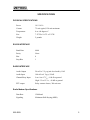
SPECIFICATIONS
PHYSICAL SPECIFICATIONS
Power
10.5-16 Vdc
Current
75 mA typical, 150 mA maximum
Temperature
0 to +60 degrees C
Size
7.25"W x 10.5"L x 2.25"H
Weight
2 pounds
RS-232 INTERFACE
Baud Rate
4800
Parity
None
Bits
8
Stop Bits
1
RADIO INTERFACE
Audio Output
20 mV to 2 V p-p (mic level audio), 1 kΩ
Audio Input
100 mV to 4 V p-p, 50 kΩ
Channel Busy Input
Low: 0 to 0.7 Vdc, <100 Ω to ground
High: 3.5 to 12 Vdc, >10 kΩ to ground
PTT output
Relay contact closure, 300 mA max
Radio Modem Specifications
Data Rate
1200 baud
Signaling
Minimum Shift Keying (MSK)
025-9209
5
Specifications
Signal Integrity
Required Signal
Strength
95% success at 12 dB SINAD
Probability of False
Data
1 in 109 (0.0000001%)
I/O SPECIFICATIONS
External Inputs
Contact Closure Inputs
Model 1708: 8 inputs
Model 1716: 16 inputs
Contact closure to ground or 0-5 V or 5-0 V voltage
change
Logic low: <500 Ω or <0.8 Vdc
Logic high: >2.5 kΩ or >2.0 Vdc
Protected to +50 VDC
Analog Inputs
Model 1708: 4 inputs
Model 1716: 8 inputs
0 to 5 Vdc analog sensor with 8-bit A/D input
External Outputs
6
Open Collector Outputs
Model 1708: 8 outputs
Model 1716: 16 outputs
12 Vdc, 100 mA max
Analog Outputs
Model 1716: 4 outputs
0 to 5 Vdc 8-bit D/A
025-9209
OPERATION
GENERAL OPERATION
The Model 1708 and Model 1716 Remote Terminal Units (RTUs) perform two basic tasks:
1. RTUs report changes in input/output to the Controller
2. RTUs respond to commands from the Controller.
Analog and digital inputs may be configured to report changes as they occur without being
polled by the Controller (report by exception). When the RTU recognizes an alarm condition,
it will check to see if the radio channel is busy. If the channel is busy, the RTU will wait for
the channel to clear. If the channel is not busy, the RTU will transmit its data and wait for a
reply from the Controller indicating that the alarm was received. If the RTU has not received
a reply within 15 seconds, it will re-send the packet and wait for a reply. In all cases, the
RTU will continue attempting to complete the transmission sequence until it receives the
correct response.
Each RTU can be configured differently so that the user can customize operation to match
the requirements of the application.
025-9209
7
Operation
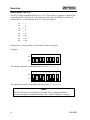
ADDRESSING THE RTU
The RTU is DIP switch addressable from 1 to 255. This is done by using the 8-position DIP
switch labeled SW1. Position #1 is the LSB and position #8 is the MSB. All switches off
corresponds to 0, and all switches on is 255. The count is binary:
#1
→
1
#2
→
2
#3
→
4
#4
→
8
#5
→ 16
#6
→ 32
#7
→ 64
#8
→ 128
Each unit on a system must have a different ID in order to respond.
Examples:
1
2
3
4
5
6
7
8
ON
OFF
The configuration above would define this unit as #3: 1 + 2 = 3
1
2
3
4
5
6
7
8
ON
OFF
The configuration above would define this unit as #26: 2 + 8 + 16 = 26
Note
The RTU may be given an address greater than 255 by changing the address
extension through the configuration menus. See “Address Extension” on page 11.
8
025-9209
Operation
CONFIGURATION
Each RTU will need to be configured prior to its use unless the factory default initialization
values are satisfactory for the application.
To configure an RTU, you will need:
1. A “dumb terminal” or a PC running in the dumb terminal mode. Software programs
such as CrossTalk, Kermit, ZCU, Procomm, and others will provide terminal
emulation on a PC.
2. A cable with a male 9-pin, D-style connector on one end to interface with the RTU
and a connector on the other end to interface with the serial port of your PC or dumb
terminal.
Note
The pins on the RTU are different from those of other serial ports found on printers
and modems. You will need to use the cable provided with the Model 1700
Controller, make up your own cable, or purchase an additional cable from Zetron
for programming the RTUs.
Accessing the RTU Program Mode
1. Connect the serial cable between J2, the 9-pin “D” style connector on the RTU, and the
serial port of the PC or dumb terminal.
2. Connect a 12-volt power supply with power off to the RTU pin 1 of P3 and ground to pin
2 of P3.
3. Make sure your dumb terminal or PC is set at 4800 baud, 8 bit, no parity, 1 stop bit.
4. Turn the 12-volt power supply on. You should see the RTU model number and the
software version displayed on the CRT.
5. Press the space bar three times to enter the Main Menu.
025-9209
9
Operation
MAIN MENU
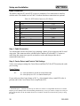
Table 2. RTU Main Menu
Menu Selections
Range
Factory Settings
{P}rekey time
0-40 (x0.1 second)
5 (0.5 second)
{C}hannel busy detect
Low or High
Low (inhibit on logic low)
Channel {B}usy Timeout
0-40 (x0.1 second)
0.5 second
{T}ransceiver type
Conventional or Trunking
Conventional
Add{r}ess extension
0-65280
0
Co{N}troller Address
0-65535
0
{G}roup Call Address
0-65535
65535
Fai{L} safe setup
{S}tore and Forward
{O}utput Definition
{D}igital Input Definition
{A}nalog Input Definition
{F}actory defaults
E{x}it
To select a menu item, press any key that is within braces {}. Simply pressing ENTER will
redisplay the current menu. If you do not press a key for 30 seconds, the RTU will
automatically exit the menus. You must press the space bar three times to re-access.
Prekey Time
This menu selection allows the user to change the delay between the time PTT is activated
and the time the MSK signaling begins. The default is 500 milliseconds and can range from 0
to 4 seconds in 100 millisecond increments.
For trunked operation, this is the delay from the time a channel-acquired signal is received on
the COR input until the data is sent. If there is no delay required (as should be with trunked
radio), set this to zero.
CAUTION
THE RTU CONTAINS A DATA COLLISION ALGORITHM. TO AVOID
MULTIPLE DATA COLLISIONS, SET THE PREKEY TIME OF EACH RTU
TO THE SAME VALUE!
10
025-9209
Operation
Channel Busy Detect
To identify when the channel is in use, the carrier must be set to inhibit transmission on
either High (+5 or open) or Low (0 V). The level entered here will PREVENT transmission.
For trunked operation, this is used the same way to inhibit transmission. The proper name for
this parameter should be “channel-acquired indication” when a trunked system is being used.
Channel Busy Timeout
Enter the amount of time (in tenths of seconds) that the channel has to be available before the
RTU can seize the channel. This can prevent the RTU from interrupting a conversation.
For trunked operation, this is used to determine that the TX indicator has stopped flashing
(requesting a channel) and is on long enough to verify that the channel has been acquired.
(This is only if you are using the TX indicator to provide the channel-acquired signal.)
Transceiver Type
This lets the user select whether the RTU is to be used on a conventional or trunking radio
system. The difference being that in trunking, you request a channel by giving PTT and in
conventional, you first look to see if the channel is available before giving PTT.
For trunked operation timing, PTT is pressed for 15 seconds while looking for a channel. If a
channel is acquired prior to the 15 seconds (this is based on the logic indication on the COR
input), the RTU will wait the Prekey delay, send the data, and release PTT. After 15 seconds,
if no channel is available, the RTU will release PTT, wait 30 seconds, and retry.
Address Extension
If you have more than 255 RTUs, enter the number to be added to the dip switch address for
this RTU. It is suggested that you enter a multiple of 256 (256, 512, 768, 1024 etc.) and use
this same number for the rest of the extended address RTUs (up to 255). Record this number
on the sheet provided on the inside top cover of the RTU.
Controller Address
Enter the address of the unit that is to receive alarms from this RTU. The default is the
Controller address 0.
Group Call Address
The Group Call Address allows outputs on several RTUs to be controlled in a single
transmission from the Model 1700 Controller. When the controller sends an output control
command to a group call address, all RTUs in the group will execute the command, but will
not send back a response (in the case of momentary outputs, each RTU makes an exception
report when the output returns to its idle state). Since the RTUs do not send response
messages, the group call address cannot be used to poll inputs or outputs.
025-9209
11
Operation
All RTUs in a system can have the same group call address, or you can achieve a zoning
effect by assigning one address to one group of RTUs and another address to a different
group. The group call address should not be the same as the RTUs DIP switch address.
Factory Defaults
This menu selection will allow the user to reset all configurable parameters to the defaults set
at the factory including input/output definitions. The user is prompted again to make sure all
definitions really should be cleared.
Exit
This menu selection will take the user out of the configuration mode and reset the RTU to its
“online” mode.
FAIL SAFE SETUP
The fail-safe menu contains several items that determine how the RTUs behave under
abnormal conditions. In many installations, these features will not be needed, so they are
disabled by default.
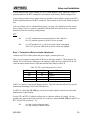
Table 3. RTU Fail Safe Setup Menu
Menu Selections
{C}ommunication failure enable
Range
Factory Settings
0-10
0 (disabled)
Time period
0 to 30 minutes
0 (disabled)
# of reports
1 to 999
100
Time out interval
1 to 10 minutes
5 minutes
Channel {U}se limits
{E}nable exception reports
enabled
{D}isable exception reports
E{X}it
Communication Failure Enable
Selecting this menu item allows you to set the number of times an exception report (power up
alarm, input change alarm, or output change alarm) is sent without acknowledgement from
its controller before the RTU enters the communications fail state.
The range is 1 to 10 times. Entering a “0” (the default value) disables communications failure
detection.
In the failed state, all outputs on the RTU will be turned off - digital outputs go in to the high
impedance state and analog outputs go to 0 volts. The outputs remain off even after communications are restored; they remain off until turned on again by a command from the
controller.
12
025-9209
Operation
WARNING
Do NOT enable the Communication Failure feature if you are using a Model
17 or Model 1700 Controller with a software version lower than 3.10. Doing
so can cause permanent loss of communications between the RTU and the
Controller and require a trip into the field to cycle power on the RTU.
Channel Use Limits
Failure of a transducer or other device attached to the inputs of an RTU may cause random
alarm transmissions that tie up the radio channel. The RTU allows you to limit the number of
exception reports (alarms) the RTU transmits within a specified period. If this number is
exceeded, the RTU stays off the channel for a while before resuming alarm transmission.
The period to monitor can be set in the range 1 to 30 minutes. The default value is zero,
which disables this feature. The number of reports allowed during the period can range from
1 to 999 (100 is the default), and the time out interval can be from 1 to 10 minutes (5 minutes
is the default).
During the time out interval, any new alarms that may be detected are buffered (until the
buffer gets full) and are sent when the interval ends.
Enable/Disable Exception Reports
The RTU can be set to poll-only mode by disabling exception reporting (alarms). This is a
global setting that overrides the alarm enables on the individual inputs. This function is
useful for temporarily disabling alarms while debugging an installation.
STORE AND FORWARD
Store and forward (also called “digi-peat” and “packet”) lets an RTU decode the information
from another RTU and retransmit that information. This solves the problem of an RTU out of
radio range of the controller. The RTU can pass its data through one or more RTUs to get to
the Controller. Remember that this will increase the amount of time required for the
transmission.
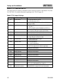
Table 4. RTU Store and Forward Menu
Menu Selections
Range
Factory Settings
{S}ource Address
0-65535
0
{D}estination Address
0-65535
0
Replacement S{o}urce Address
0-65535
0
Replacement D{e}stination Address
0-65535
0
{N}ext Slot
E{x}it
025-9209
13
Operation
Slot No.
There are up to 16 slots to configure.
Source Address
Input the address of the transmitting unit.
Destination Address
Input the address of the unit that the transmitting unit is trying to reach.
Replacement Source Address
Input the new address of the transmitting unit.
Replacement Destination Address
Input the new destination address of the transmitting unit.
Next slot
Go to the next slot.
Exit
This selection will take the user back to the main menu.
Example
Controller Unit
#0
RTU
#5
RTU
#150
If RTU #150 is out of range of Controller Unit #0, but RTU #5 is in range of both Controller
Unit #0 and RTU #150, we would configure RTU #5 as the store and forward unit with the
values shown in Table 5.
Table 5. Store and Forward Address Assignments
Parameter
Parameter
Value
SLOT # 1 Source Address
0
SLOT # 2 Source Address
Destination Address
10
Destination Address
5
Replacement Source Address
5
Replacement Source Address
10
Replacement Destination Address
0
Replacement Destination Address
14
Value
150
150
025-9209
Operation
We have configured RTU #5 to act as the store and forward unit between Controller Unit #0
and RTU #150. If Controller Unit #0 tries to poll RTU #10 (a fake address for RTU #150),
the transmissions listed in Table 6 will occur.
Table 6. Store and Forward Traffic Flow
Transmission
From
To
Description
No. 1
#0
#10
Controller Unit #0 polls RTU #10.
No. 2
#5
#150
RTU #5 has been configured in Slot #1 to recognize
and re-send all transmissions of 0-to-10 as 5-to-150.
No. 3
#150
#5
RTU #150 receives the poll from RTU #5 and sends
its response back to RTU #5.
No. 4
#10
#0
RTU has been configured in Slot #2 to recognize and
re-send all transmissions of 150-to-5 as 10-to-0. This
completes the cycle.
Note
Enter the ID of the out-of-range RTU higher than the largest ID of the in-range
RTUs. Set the Controller address in the out-of-range RTU to its store and forward
unit. This is done in the Co{N}troller Address section of the main menu.
DIGITAL INPUT DEFINITION
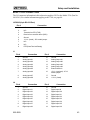
Table 7. RTU Digital Input Definition Menu
Menu Selections
Range
{E}nable Input
Factory Settings
Enabled
{D}isable Input
N/{O} Input
N/{C} Input
{S}tatus Input
De{b}ounce time
Status
0-65535 (x0.1 s)
0 seconds
{N}ext Input
E{x}it
These menu selections control the performance of each input.
Enable Input
To allow the RTU to report an alarm from this input without being polled, the input must be
enabled.
025-9209
15
Operation
Disable Input
If the input is disabled, its status will still be sent during a poll response, but any change in
the state of the input will not cause the RTU to transmit an alarm.
N/O Input
In the normally open mode, the input will cause an alarm transmission whenever it detects a
change from high to low or open to closed (closure to ground).
N/C Input
In the normally closed mode, the input will cause an alarm transmission whenever it detects a
change from low to high or closed to open.
Status Input
A status input will send an alarm message every time the input changes state. When the input
changes, the alarm message will indicate the new state, high or low.
Debounce Time
Each input has a “debounce” time. Debounce is the amount of time the input must reside in
the alarm condition in order to trigger the alarm. If this time is set to 3 seconds, the input
must stay in the alarm condition for more than 3 seconds before the input will transpond an
alarm message. The default setting is for no debounce time. The debounce time can be set
from 0 to 6553.5 seconds in 0.1 second increments.
Next Input
This menu selection will increment the current input number for modification. If this is the
last input on the RTU, the menu will wrap back to input #1.
Exit
This selection will take the user back to the main menu.
16
025-9209
Operation
DIGITAL OUTPUT DEFINITION
Table 8. RTU Digital Output Definition Menu
Menu Selections
Range
{L}atched mode
{M}omentary mode
Factory Settings
Latched
0-255 seconds
0 seconds
{O}utput ON
{F}orce output OFF
{N}ext output
E{x}it
Latched Mode
When latched mode is selected, if the output is commanded on, it will remain in that position
until it is commanded off (or power is removed).
Momentary Mode
When momentary mode is selected, the user will be prompted for a time in seconds that the
output is to remain in the on position after the output is commanded on. This value, 0-255,
will cause the output to automatically return to the off position after the time has expired.
Output On
This menu selection allows the user to locally control the outputs. This is used to check
operation and setting of the momentary time.
Force Output Off
This menu selection allows the user to locally control the outputs. This is used to check
operation and setting of the momentary time.
Next Output
This menu selection allows the user to increment the current output number. Once
incremented, the parameters for the new current output will be displayed along with the
menu. Once the user reaches the last output for the RTU, this item will change the current
output back to output number 1.
Exit
This selection takes the user back to the main menu.
025-9209
17
Operation
ANALOG INPUT DEFINITION
Table 9. RTU Analog Input Definition Menu
Menu Selections
Range
{E}nable Input
Factory Settings
Enabled
{D}isable Input
{H}igh Threshold Value
0-5.00 volts
5.00 volts
{L}ow Threshold Value
0-5.00 volts
0.00 volts
High {R}eset Value
0-5.00 volts
5.00 volts
Lo{w} Reset Value
0-5.00 volts
0.00 volts
Accumulator {S}ampling Rate
1 to 65535 (x0.1
second)
10 (1 sample per
second)
% {C}hange alert
0 to 100%
1.9%
% Change de{B}ounce
0 to 250 (x0.1
second)
0.5 second
{N}ext Input
E{x}it
Enable Input
To allow the RTU to report an alarm from this input without being polled, the input must be
enabled.
Disable Input
If the input is disabled, its status will still be sent during a poll response, but any change in
state of the input will not cause the RTU to transmit an alarm.
High Threshold
If the voltage being measured exceeds this threshold and the input is enabled, the RTU will
automatically report an alarm. The threshold value is 0-255, 0 corresponding to 0 volts and
255 corresponding to 5 volts.
Low Threshold
If the voltage being measured drops below this threshold and the input is enabled, the RTU
will automatically report an alarm. The threshold value is 0-255, 0 corresponding to 0 volts
and 255 corresponding to 5 volts.
The threshold values set the limit. A low threshold of 0 and a high threshold of 255 effectively
disable the alarm since these values cannot be surpassed.
18
025-9209
Operation
High Reset
To provide for hysteresis, set this value slightly below the high threshold value. The voltage
being measured must drop below the High Reset value before another alarm can be initiated.
This prevents chattering when a voltage hovers right at the threshold value.
Low Reset
To provide for hysteresis, set this value slightly above the low threshold value. The voltage
being measured must rise above the Low Reset value before another alarm can be initiated.
Accumulator Sampling Rate
Set the time between samples in 10th seconds. For example, “1” is 10 samples per second,
“2” is 5 samples per second, “100” is one sample every 10 seconds, and “1000” is one
sample every 100 seconds. The valid range is 1 to 65535, which represents from 0.1 to
6553.5 seconds between samples.
% Change Alert
% Change alert is the percent change of full scale from the last reported value that will cause
another report. For example, if we are measuring feet of water in a 100-foot tank and we
wish to know a minimum of every 4-ft change, we would set the % Change alert to 4/100 or
4.0%. If our starting value is 30 ft and the tank is rising, we should get an update at 34 ft, 38
ft, 42 ft, etc.
% Change Debounce
% Change de{B}ounce is the amount of time in seconds that the change must exist before the
update can be sent. If, in the example in the previous paragraph, we have the debounce set to
5 seconds and the level rises from 30 to 34 feet for 3 seconds and then drops to 33 feet, no
report would be sent. This programming option helps filter out noise spikes and reduce
airtime usage.
Next Input
This will increment the current input number for modification. If the current input number is
the last input for the RTU, the menu will wrap back to input #1.
Exit
This selection will take the user back to the main menu.
025-9209
19
Operation
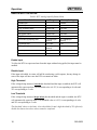
SYSTEM OPERATIONAL LIMITS
Inputs
Chatter
Chattering occurs when a status being monitored changes
rapidly, that is, more than once every few seconds.
Chattering can cause the RTU to send multiple reports using
excessive airtime. The debounce time and hog time in the
RTU should be used to prevent excessive transmissions.
Broken Connection
Analog Input - The voltage read by the analog input would
float, following the voltage of the previous analog input.
More than 5 kΩ source impedance will increase
susceptibility to noise.
Digital Input - The digital inputs have a +12 Vdc pull up and
will read a logic high with nothing connected.
Outputs
20
Power Up State
The analog inputs power up in a 0 volt state. The digital
outputs power up in a high impedance, open collector state.
Power Off State
The analog inputs power off in a 0 volt state. The digital
outputs power off in a high impedance.
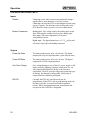
Unit Over Voltage
Over voltage damage to any of the I/O, power supply, or RF
inputs caused by lightning, improper connection, etc. can
cause unpredictable behavior in any of the electronic
components. The RTU provides safeguards against this type
of damage, but damage is still possible. Full testing of
suspect hardware should be performed.
RS-232
Currently the RTU only uses the serial port for
programming. If the RTU is left in programming mode, the
unit times out after 30 seconds and normal operation
resume. While in programming mode, transmission and
reception of data via FFSK is suspended.
025-9209
Operation
Power
Brown Power
There is a low power reset circuit in the RTU which will
disconnect power when supply voltage drops below 9.35
volts ±5%.
Power Up Conditions
The RTU performs a self-test on power up. If there are
errors detected during the self-test, operation is suspended.
The digital and analog output states are designed to be in a
high impedance and 0 Vdc state respectively. If the self-test
fails, these default values may not be valid.
Radio Connections and Associated Problems
Loss of transmit or receive audio anywhere along the communications path (repeater, radio,
connector or RTU) will cause a communications failure at both the RTU and Controller.
Carrier Detect
Failed Connection - If the carrier detect fails, the RTU will
transmit at will or be inhibited from transmitting.
Transmitting at will increases the risk of collisions. Never
transmitting causes a communications failure alarm at the
Controller and a communications failure state at the RTU.
Push to Talk
If Push to Talk fails, the radio will either transmit no data or
be locked in transmit and block all other transmissions on
the channel. There are jumper settings to provide proper
default open or closed conditions for power off and standby
for most radios.
Transmit Request
Failed Connection - If the transmit request line is
disconnected, collisions with the RTUs sharing the same
radio may increase. If the transmit request line is shorted,
this will cause a communications fail alarm at the Controller
and a communications fail state at the RTU.
Addressing
DIP Switch Failure - If an RTU has a DIP switch failure
causing a change in address, there is no provision for the
Controller to recognize the error other than to show a
communications failure for the old address. Data sent by the
new address has the potential to false the data of another
RTU at the same address.
If there is a DIP switch failure causing a change in address,
the Controller will not be able to communicate with the
RTUs and possibly the PC.
025-9209
21
Operation
Radio System
A radio stuck in transmit for any reason (PTT held in,
electronic failure, chattering PTT, etc.) will prevent or
interfere with other transmissions. Radios should provide a
PTT timer that prevents continuous transmission for
extended periods, usually three minutes. This only helps if
the radios are functioning properly. It will not prevent all
cases of transmit lock-out.
RS-232
Transmit or receive data failure will cause loss of
communications between the PC and the Controller. This
will cause communications failure states at all RTUs and the
Controller.
Buffering
If communications fail, the Controller will buffer 200 bytes,
a minimum of 10 messages. After the buffer is full, the
controller will stop acknowledging the RTUs and a critical
system communications fail status will occur.
Ground
Poor grounding or no common signal ground can cause
intermittent communications. A power cycle may appear to
cure this situation for short periods of time.
Critical System Failures Summary
Critical system failures can be caused by any of the following conditions:
22
•
Chattering input causing repeated transmissions
•
Radio stuck in transmit due to:
¾ PTT held on by RTU, user, or radio failure with no timeout
¾ Radio locked in transmit due to radio failure
¾ Carrier from another radio system causing interference
¾ Hardware/firmware failure causing chattering PTT
•
Repeater down
•
Controller radio down with no standby or backup
•
Controller is down due to:
¾ COR stuck active
¾ Power failure
¾ Equipment failure
¾ Hardware/firmware failure causing chattering PTT
•
RS-232 connection to Controller is down
•
PC or software failure
025-9209
MODBUS SYSTEM SET UP
This section describes the functioning of the Model 1700 controller and Model 1708/1716
RTUs in a MODBUS system.
MODBUS OPTION
The Model 1700 controller has an optional implementation of the industry standard
MODBUS protocol. This option is provided by means of a replacement EPROM containing
code to support the MODBUS protocol when communicating with the PC running the
MODBUS application. The Model 1708 and Model 1716 RTUs do not require any
modification to support the MODBUS protocol if they are communicating only with the
Model 1700. There are optional EPROMs for both of the RTU models that will allow them to
be interfaced directly to the PC, by-passing the Model 1700 controller. The MODBUS
implementation makes the devices compatible with nearly all SCADA programs as well as
with many PLCs.
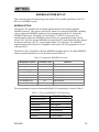
The Model 1700 is compatible with most MODBUS programs that use five-digit MODBUS
addresses and limit themselves to the functions listed in Table 10.
Table 10. Compatible MODBUS Functions
MODBUS Function
Function Code
Used for...
Read Coil Status
01
Digital Outputs
Read Input Status
02
Digital Inputs
Read Holding Registers
03
Analog Outputs, Counters, Accumulators
Read Input Registers
04
Analog Inputs
Force Single Coil
05
Digital Outputs
Preset Single Register
06
Analog Outputs, Counters, Accumulators
Force Multiple Coils
0F
Digital Outputs
Preset Multiple Registers
10
Analog Outputs, Counters, Accumulators
The correspondence between Zetron and MODBUS I/O terminology is listed in Table 11.
Table 11. Zetron and MODBUS I/O Terminology
Zetron I/O Type
025-9209
MODBUS I/O Type
Digital/Relay Output
Coil
Digital Input
Input Status
Analog Input
Input Register
Analog Output
Holding Register
Accumulator
Holding Register
Counter
Holding Register
Run-time
Holding Register
23
MODBUS System Set Up
COMMUNICATIONS
In a MODBUS system using radio or wireline communications, only the controller speaks
MODBUS. For queries addressed to RTUs, the controller translates back and forth between
the MODBUS protocol and the RTU radio protocol.
There are two ways to set up a MODBUS system using the Model 1700 controller with the
MODBUS option: Polled-only and report-by-exception.
Polled-Only System
In a polled-only system, the “master” PC or PLC controls all communication in the system.
When a MODBUS query is sent to an RTU through the Model 1700 controller, the controller
always translates the query to the RTU FFSK protocol and sends it out over the radio. When
the RTU responds, the response is translated from RTU FFSK protocol to MODBUS
protocol and sent back to the master through the serial port of the Model 1700 controller.
Configuring a system as polled-only gives the master complete control over communications,
particularly use of the radio channel, which can be a bottleneck. Radio communications
occur only when the master polls an RTU. The RTUs never transmit except in response to a
poll. There is no possibility of data collisions, which completely eliminates one cause of
communication failures.
On the other hand, there is one major disadvantage to a polled-only system. The master will
not be able to see changes in RTU input status that occur between polls. It only sees the
current input status at the time each poll response is sent. Any RTU input changes that occur
between polls are lost.
Report-By-Exception System
In a report-by-exception system, RTUs report changes in I/O status as they occur without
waiting to be polled by the master. The Model 1700 controller stores this status within its
own memory. When the master polls for status from an RTU, the Model 1700 controller
builds the poll response from this stored status, and sends it back to the master immediately.
A radio transmission occurs only if the master tries to control an RTU output or asks for
RTU status that the Model 1700 controller does not have. In this case, the Model 1700 must
try to obtain the RTU status over the radio before it can build the response to send back to the
master.
A report-by-exception system should also use the Model 1700 controller autopoll feature.
This causes the Model 1700 to periodically poll the input status for all RTUs in the system. If
an RTU or its radio fails, the Model 1700 will not get a response to the poll and it will
invalidate the status of the RTU. The next time the master tries to poll that RTU, a
communications failure will occur unless the RTU has been fixed.
The advantage to a report-by-exception system is that the master sees changes in RTU I/O
status almost immediately. The main disadvantage is that data collisions can occur between
polls from the master and exceptions from RTUs or between exceptions from different
24
025-9209
MODBUS System Set Up
RTUs. In a large system with lots of I/O activity, this can result in frequent communications
failures.
Which Is Better - Polled-Only or Report-By-Exception?
A polled-only system is easier to configure. Problems in a polled-only system can be much
easier to diagnose. For example, if a communications failure occurs, it can not be due to data
collisions, but is probably a true indication of a problem with the RTU, radio or
communications path. Therefore, a polled-only system should be favored over a report-byexception system.
A report-by-exception configuration may be needed if the system is very large so that the
polling loop takes a long time, or if some signal changes are short duration and need to be
reported automatically by the RTU. For a small system where a radio channel is also used for
voice communications, report-by-exception can reduce the amount of airtime used for data
transmission.
MODBUS MASTER REQUIREMENTS
In a MODBUS system, the “master” will typically be a PC running a software application
that is compatible with the MODBUS protocol. The following list contains some of the major
requirements for this “master” to be compatible with the Model 1700 controller and the
Model 1708/1716 RTUs.
•
The serial port(s) on the PC must be capable of supporting a three-wire version of RS232 communications (Tx, Rx, ground). The communication parameters used are: 4800
baud, 8 data bits, no parity, and 2 stop bits.
•
The application must have a configurable polling timeout period. The range must
allow enough time for a radio transmission to be sent to an RTU and for the response
to be sent back (3 to 5 seconds minimum).
•
The application must limit itself to the command codes listed in Table 10.
•
The application must support the MODBUS RTU protocol (as opposed to the
MODBUS ASCII or MODBUS Plus protocols).
Fortunately, most PC software packages that support MODBUS protocol follow these rules.
In some software packages, MODBUS protocol support is a standard feature. For others, the
MODBUS protocol must be purchased separately as an option. As long as the software meets
the above requirements, it will work with the Model 1700 controller.
Some of the software packages that work with the Model 1700 MODBUS option are listed
on page 36.
025-9209
25
MODBUS System Set Up
CONFIGURING THE 1700 CONTROLLER
When using the MODBUS option, the Model 1700 controller address is usually set to “1”
(DIP switch 1 ON, DIP switches 2 through 6 OFF). Any address in the range of “1” to “63”
could be used. It should never be set to “0”.ii
The Model 1700 controller has built-in configuration menus that can be accessed through a
PC with a terminal program. For more information on the general configuration of a
controller, please see the “PROGRAMMABLE FEATURES” subsection of the “Model 1700
Controller Installation and Operation” manual, part number 025-9209. Only the menu items
that apply to the MODBUS option are discussed here.
MODBUS Menu
When the MODBUS option is installed in the controller, the main menu displayed contains
an additional item right after the RS232 {W}atchdog item, {M}odbus. Typing an “m” will open
the menu listed in Table 12.
Table 12. 1700 Controller MODBUS Menu
Menu Selections
Range
Factory Settings
{R}TU status storage
Enable, Disable
Enabled
{A}utopoll...
Autopoll interval
(0 to 65535 minutes)
First autopoll RTU
(1 to 255)
Number of RTUs
(1 to 255)
Autopoll interval = 0
First RTU = 1
Number of RTUs = 1
E{x}it
The following two subsections make reference to the items on the MODBUS menu.
Polled-Only Configuration
For a MODBUS, polled-only system, you must configure the following items. This is in
addition to any other parameters you configure on the controller.
1.
From the controller main menu, type “M” to open the MODBUS menu.
2.
From the MODBUS menu, type “R” to open the RTU Status Storage item.
3.
At the RTU Status Storage prompt, type “D” to disable the status storage feature. This
should return you to the MODBUS menu.
ii
The address “0” is a reserved address in the MODBUS protocol. If you give a controller or RTU an address of
“0”, the PC or PLC will not be able to communicate with it.
26
025-9209
MODBUS System Set Up
4.
From the MODBUS menu, type “A” to open the Autopoll menu.
5.
From the Autopoll menu, type “I” to open the Interval item.
6.
At the Autopoll Interval prompt, type in zero (0) and then press ENTER to disable the
autopoll feature.
7.
At the Autopoll menu, type “X” to return to the MODBUS menu. At the MODBUS
menu, type “X” to return to the controller main menu.
You may now exit the programming mode or continue with any other configuration
programming you need to perform on this controller.
Report-By-Exception Configuration
For a MODBUS, report-by-exception system, you must configure the following items. This
is in addition to any other parameters you configure on the controller.
1.
From the controller main menu, type “M” to open the MODBUS menu.
2.
From the MODBUS menu, type “R” to open the RTU Status Storage item. At the
RTU Status Storage prompt, type “E” to enable the status storage feature. This should
return you to the MODBUS menu.
3.
From the MODBUS menu, type “A” to open the Autopoll menu.
4.
From the Autopoll menu, type “I” to open the Interval item. At the Autopoll Interval
prompt, type in the time in minutes that the 1700 controller must wait in between
polls of all the RTUs in the system. Press ENTER to return to the Autopoll menu.
5.
From the Autopoll menu, type “F” to open the First RTU item. At the First RTU
prompt, type in the address of the lowest numbered RTU in the system. Press ENTER
to return to the Autopoll menu.
6.
From the Autopoll menu, type “N” to open the Number of RTUs item. At the Number
of RTUs prompt, type in the total number of RTUs in the system. (It is highly
recommended that the RTUs be consecutively numbered in any system that is
automatically polled.) Press ENTER to return to the Autopoll menu.
7.
At the Autopoll menu, type “X” to return to the MODBUS menu. At the MODBUS
menu, type “X” to return to the controller main menu.
8.
At the main controller menu, type “R” to open the Radio menu. At the Radio menu,
type “R” to open the RTU response timeout item. At the RTU response timeout
prompt, type in the number of seconds the controller should wait for an individual
RTU to respond and press ENTER. This will return you to the Radio menu.
9.
From the Radio menu, type in “X” to return to the controller main menu.
025-9209
27
MODBUS System Set Up
You may now exit the programming mode or continue with any other configuration
programming that you need to perform on this controller.
Note
The RTU Response Timeout sets the period for which the controller will wait for a
response whenever it polls an individual RTU. A period of 5 to 10 seconds will
normally be adequate; however, if the store-and-forward method is being used, the
timeout period might have to be set to a larger value. This value needs to be the
smallest number of seconds that produces reliable results because it can affect the
total amount of time required to poll all of the RTUs in the system.
RS-232 Watchdog Configuration
The Model 1700 controller has the ability to monitor the RS-232 serial connection for
MODBUS protocol queries. If the master fails to send a MODBUS query for a specific
amount of time, the Model 1700 controller will turn on its output number “1”. This output
could be connected to some kind of alarm that would notify the system operator that either
the master itself has failed or the RS-232 connection between the master and the Model 1700
controller has failed.
This feature can be enabled or disabled, and the timeout period set through the Model 1700
controller RS-232 watchdog menu. The default setting is disabled. The range for the timeout
period is 10 to 65535 in seconds (just over 18 hours maximum).
CONFIGURING THE RTUs
Unless an RTU is interfaced directly to the master PC that is running the MODBUS program,
there is no special configuration necessary. The RTU communicates with the Model 1700
and the controller takes care of translating the information received into the MODBUS
protocol format. The same applies to any commands sent from the master PC out to the
RTUs by means of the controller.
If the RTU is to interfaced directly to a serial port on the master PC, then it must have the
optional MODBUS version of the firmware installed. This version of the RTU firmware does
not show any radio configuration options since the RTU communicates directly with the
master PC.
Assign Addresses
The default setting for the RTU address is zero. This should be set to a number between one
and 255 (not the same address as the Model 1700 controller). Each RTU must have a unique
address. See “ADDRESSING THE RTU” on page 8 for more information on setting the
RTU address.
28
025-9209
MODBUS System Set Up
MODBUS Version of the RTU Menu
When you access the program mode for a Model 1708/1716 that has been equipped with the
MODBUS version of the RTU firmware, a shortened version of the main menu appears.
Table 13 lists this modified menu. Basically, all the menu items dealing with radio
communication or the controller addressing have been removed.
Table 13. RTU Main Menu with MODBUS Option Installed
Menu Selections
{O}utput Definition
{D}igital Input Definition
{A}nalog Input Definition
RS232 {W}atchdog...
{F}actory defaults
E{x}it
With the exception of the last two menu items ({F}actory defaults and E{x}it), typing in the
letter for a menu item opens a submenu. The I/O menu items work just as they would for a
regular RTU. The item that is new to the MODBUS version is the RS232 {W}atchdog item.
This is the same watchdog feature offered in the Model 1700 controller menu. Since the RTU
is connected to the master PC in this configuration, it has the same need to alert the system
operator if the serial communication link to the master PC is lost.
CONFIGURING THE MASTER PC (OR PLC)
Each MODBUS software package or PLC is configured differently, so we can only give
general guidelines for configuring them here. The areas we will touch on include: serial
communications, polling intervals, timeout periods, and retries.
Serial
Communications
The serial communication parameters used by the master never
vary. They must always be set to 4800 baud, 8 data bits, no parity,
and 2 stop bits.
Polling Intervals
Report-by-Exception
In a report-by-exception system, the polling interval used by the
master can be set to a short period (on the order of 1 second). Much
of the time the Model 1700 will be responding to the polls using the
last known RTU status stored in its memory.
Polled-Only
In poll-only systems, the polling interval is generally set to a value
that allows the master enough time to have polled all the RTUs in
the system. Example: if it takes five seconds for each RTU, and the
system has 10 RTUs, the polling interval would be 50 seconds
minimum (it could be longer). Some software packages allow
different polling intervals for each RTU, so more important or
025-9209
29
MODBUS System Set Up
rapidly changing signals could be polled more often than less
important or slowly changing signals.
Timeout Periods
The timeout period should be the same for both poll-only and
report-by-exception systems. The period should be set to minimum
time that it takes for a poll to go out over the radio to an RTU and
for the response to return to the master. A typical value is five
seconds. However, if the RTUs are doing store-and-forward, or
there is a lot of traffic on the radio channel, a longer timeout may be
needed.
Retries
The master can usually be configured to retry a poll for a specified
number of times before giving up and signaling a communications
failure for that RTU. The appropriate setting for retries is really
system dependent, but a value of 2 or 3 is usually a good starting
place.
BASIC MODBUS I/O ADDRESSING
The basic I/O capability of the Model 1700 controller consists of four digital outputs. These
are open-collector outputs capable of sinking up to 100 mA and dealing with voltages up to
50 Vdc.
In the MODBUS protocol, each I/O point is given a unique address. This address not only
identifies a unique point within the system, it also tells the master what type of I/O point the
address identifies.
The MODBUS protocol also has its own nomenclature for the various I/O types. It also has
its own set of ranges for data. Table 14 shows the relationship between MODBUS
nomenclature for I/O addressing and the Zetron nomenclature used in the Model 1700,
Model 1708, and the Model 1716.
Table 14. MODBUS versus Zetron I/O Addressing
Zetron Values
30
MODBUS Values
I/O Type
Address
Range
Value
Range
I/O Type
Address
Range
Value Range
(Raw)
Digital Outputs
1 to 16
OFF, ON
Coils
1 to 16
0 (off), 1 (on)
Digital Inputs
1 to 16
Open Circuit,
Grounded
Input Status
10001 to
10016
0 (open circuit)
1 (grounded)
Analog Inputs
1 to 8
0 to 5 V or
0 to 20 mA
Input Registers
30001 to
30008
0 to 32767
Analog Outputs
1 to 4
0 to 5 V
Holding
Registers
40001 to
40004
0 to 32767
025-9209
MODBUS System Set Up
Within the MODBUS protocol, the Input Status and Input Register signal types (digital and
analog inputs) are read-only. The Coil and Holding Register signal types (digital and analog
outputs) may be both read from and written to.
When configuring the MODBUS master, the MODBUS addresses and value ranges must be
used. Table 15 lists the allowable range values in relation to the signal types.
Table 15. MODBUS Values versus Signal Types
I/O Type ⇓ MODBUS Value ⇒
0
1
Coil (digital output)
OFF (open circuit)
N/A
ON (grounded)
Input Status
OFF (open circuit
or high voltage)
N/A
ON (ground or low
voltage)
0
6553
32767
I/O Type ⇓ MODBUS Value ⇒
Input Register (analog input)
0 V or 0 mA
1 V or 4 mA
5 V or 20 mA
Holding Register (analog output)
0V
1V
5V
The most common usage for analog inputs and outputs is with transducers that convert some
real world value either into a voltage (in the range 0 to 5V or 0 to 10V) or a current (in the
range 4 to 20mA). Most MODBUS master software packages provide a way to configure
input registers and holding registers so that the conversion from raw units used in the
MODBUS protocol to real world units is done automatically.
Here is an example. A sensor that measures water flow and outputs a current of 4mA for a
flow of 0 gal/min and a current of 20mA for a flow of 100 gal/min. This sensor is connected
to analog input number 5 of a Model 1716 RTU. In the MODBUS master software, input
register 30005 would be configured with a raw range of 6553 (4mA) to 32767 (20mA) and a
real world range of 0 gal/min to 100 gal/min.
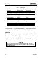
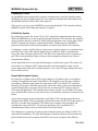
USING ACCUMULATORS AND COUNTERS
Configuring the master to be able to access accumulators and counters is more difficult than
for basic RTU I/O, and requires a good working knowledge of the MODBUS master
software package.
Analog input accumulators keep a running total of the analog input value over a period of
time. There is one accumulator for each analog input on the Model 1708 or Model 1716
RTU. Each accumulator consists of three values: the accumulated total (sum of samples from
the analog input), the total number of samples taken, and the sample rate (how often the
analog input is read).
Accumulators are usually used to keep a running total of some flow through a system. For
example, if a sensor measuring flow in gal/min is connected to a Model 1708 RTU, the total
flow in gallons can be tracked through the use of an accumulator. Accumulators can also be
used to calculate the average value of an analog input.
025-9209
31
MODBUS System Set Up
There is one digital input counter for each input of the Model 1708 or Model 1716 RTU.
Each counter consists of two values: the count and the time period since the counter was last
cleared.
The count value increments each time the input activates. When the input is set up as status
mode, the count increments every time the input changes state. If the input is set up as
normally open or normally closed, the count increments when the input is grounded or
disconnected respectively.
The accumulators and counters are accessed through MODBUS holding registers. Each
accumulator or counter value (except for the accumulator sample rate) is spread across three
separate holding registers. The lower four decimal digits are in the first register, the middle
four decimal digits in the middle register, and the upper four decimal digits in the third
register. The example in Table 16 shows accumulator 1 with a current accumulated value of
2,156,349,078, number of samples of 634,127,890, and sample rate of 2,354:
Table 16. How Accumulator 1 Stores Data
Register
Value
Description
41011
9078
Accumulated Value lower four decimal digits
41012
5634
Accumulated Value middle four decimal digits
41013
0021
Accumulated Value upper four decimal digits
41014
7890
Number of Samples lower four decimal digits
41015
3412
Number of Samples middle four decimal digits
41016
0006
Number of Samples upper four decimal digits
41017
2354
Sample rate (the sample rate uses one register)
Some MODBUS software packages (e.g. WonderWare’s Intouch) can automatically combine
these registers into a single value. Others, (e.g. National Instrument’s Lookout) require the
user to combine the registers into a single value in a “script”. For example, in Lookout, the
“script” for the accumulated value might look like the following equation,
(((Rtu1.41013 × 10000) + Rtu1.41012) × 10000) + Rtu1.41011
Queries to read an accumulator or counter must request all associated registers or an illegal
data address exception will be returned. An illegal data address exception will also be
returned to queries that overlap accumulator or counter address boundaries by requesting
more than nine registers.
Writing to the first holding register address used by particular accumulator or counter will
cause it to be cleared. The value written does not matter; the act of writing to the register
causes the clearing. It is not possible to clear just part of an accumulator or counter. For
example, you cannot clear the accumulator total without also clearing the number of samples.
32
025-9209
MODBUS System Set Up
An illegal data address exception will be returned to queries beginning at unused addresses,
40005 - 41010, 41088 - 42010, and 42167 - 99999.
Only one accumulator or counter can be polled at a time.
Table 17. Analog Accumulator Holding Register Addresses
Accumulator
Value
# Samples
Sample Rate
1
41011 - 41013
41014 - 41016
41017
2
41021 - 41023
41024 - 41026
41027
3
41031 - 41033
41034 - 41036
41037
4
41041 - 41043
41044 - 41046
41047
5
41051 - 41053
41054 - 41056
41057
6
41061 - 41063
41064 - 41066
41067
7
41071 - 41073
41074 - 41076
41077
8
41081 - 41083
41084 - 41086
41087
Table 17 shows the MODBUS holding register addresses used for analog input accumulators.
The average value of the accumulator and the total accumulated value - scaled to real world
units - can be calculated with the formulas presented below. An example will follow to help
clarify things, but first, some definitions.
Values to be calculated are:
A
T
P
= Average analog input value scaled to real world units.
= Total accumulated value, scaled to real world units.
= The time period, in seconds, that the accumulator has been running.
Values returned when the accumulator is read are:
V
N
R
= Accumulator value, unscaled.
= Accumulator number of samples.
= Sample rate
Values that are dependent on the sensor being used are:
ML
MH
SL
SH
I
= lowest real world value measured by the sensor.
= highest real world value measured by the sensor.
= sensor output corresponding to ML - in Volts or mA.
= sensor output corresponding to MH - in Volts or mA.
= analog input range - 5 Volts or 20mA depending on the type of sensor.
The formula for calculating the average analog input value in real world units is:
025-9209
33
MODBUS System Set Up
V×I
MH − ML
A=
− SL ×
+ ML
N × 256
SH − SL
The sample rate is returned in 10ths of a second. The default sample rate is 10, or 1 sample
per second. The time period (in seconds) over which the accumulation took place can be
calculated as:
P = N × R ÷ 10
Once the scaled average value and time period are known, the total can be calculated by
multiplying the average value by the time period. If the time units for the sensor are
something other than seconds, a conversion factor will also have to be included.
T=
A×P
SecondsPerSensorTimeUnits
Here is an example. We will use the same sensor that we used in our discussion of analog
input configuration. It measures water flow and outputs a current of 4mA for a flow of 0
gal/min and a current of 20mA for a flow of 100 gal/min. When the accumulator is read, we
get a value of 12345678, number of samples of 66666 and sample rate of 20. Therefore, we
know the following:
V = 12345678
N = 66666 samples
R = 20
ML = 0 gal/min
MH = 100 gal/min
SL = 4 mA
SH = 20 mA
I = 20 mA
Plugging these into the equation for the scaled average value results in the following
equation.
12345678 × 20mA
100gal / min − 0gal / min
A=
− 4mA ×
+ 0gal / min
65432 × 256
20mA − 4mA
6.25gal / min
A = (14.74mA − 4mA ) ×
+ 0gal / min
1mA
A = 67.13gal / min
The time period over which the value was accumulated is:
P = 65432 × 20 ÷ 10
P = 130864Sec
Finally, the total scaled accumulated value is:
34
025-9209
MODBUS System Set Up
T=
67.13gal / min × 130864Sec
60Sec / min
T = 146415gal
Table 18 shows the MODBUS holding register addresses used for digital input counters.
Table 18. Digital Input Counter Holding Register Addresses
Counter
Value
Period
Counter
Value
Period
1
42011 – 42013
42014 - 42016
9
42091 - 42093
42094 – 42096
2
42021 – 42023
42024 - 42026
10
42101 - 42103
42104 – 42106
3
42031 – 42033
42034 - 42036
11
42111 - 42113
42114 – 42116
4
42041 – 42043
42044 - 42046
12
42121 - 42123
42124 – 42126
5
42051 – 42053
42054 - 42056
13
42131 - 42133
42134 – 42136
6
42061 – 42063
42064 - 42066
14
42141 - 42143
42144 – 42146
7
42071 – 42073
42074 - 42076
15
42151 - 42153
42154 – 42166
8
42081 – 42083
42084 - 42086
16
42161 - 42163
42164 – 42166
The counter value, as mentioned previously, is a count of the number of times the
corresponding digital input has activated. This can be converted to engineering units simply
by multiplying the count by a conversion factor. For example, if a flow sensor outputs one
pulse for every 100 gallons of flow through a pipe. The count can be multiplied by 100 to get
the total flow in gallons.
The counter period is returned in 10ths of a second, so the period in seconds is:
Counter period in seconds = Period ÷10
025-9209
35
MODBUS System Set Up
SOFTWARE PRODUCTS FOR THE MODBUS PROTOCOL
The following list contains some of the software packages known to work with the Model
1700 Controller MODBUS option. Please note that Zetron does not sell or support these
packages. For sales and support, please contact the manufacturer directly.
FIX
Lookout
Intellution
One Edgewater Drive
Norwood, MA 02062
National Instruments Corporation
11500 North Mopac Expressway
Austin, TX 78759
Tel: 781-769-8878
Fax: 781-769-1990
www.intellution.com
Tel: 512-794-0100
Fax: 512-683-8411
www.NI.com/lookout
Genesis
RealFlex
Iconics
100 Foxborough Boulevard
Foxborough, MA 02035
RealFlex Systems Inc.
12000 Aerospace Avenue, Suite 300
Houston, TX 77034
Tel: 508-543-8600
Fax: 508-543-1503
www.iconics.com
Tel: 281-922-4357
Fax: 281-922-5109
www.realflex.com
InTouch
Wonderware
100 Technology Drive
Irvine, CA 92618
Tel: 949-727-3200
Fax: 949-727-3270
www.wonderware.com
36
025-9209
SET UP AND INSTALLATION
INSTALLATION
The Model 1708/1716 may be wall-mounted or mounted within a standard industrial
enclosure. See the Model 1700 series enclosure outline (024-0057, page 52) and instructions
(024-0056, page 53) for details on mounting the unit.
Power Connection
The power connection is made on the same connector as the radio connections. The RTU
operates from 10.5-16 Vdc. Since it requires less than 150 mA, the radio power supply (if it
provides 10.5-16 Vdc) is often used to power the RTU. A 12-volt sealed lead acid battery
(Gel Cell) can be used with a 12-volt power supply to power the radio and RTU and to
provide back-up operating power in case of a main power failure.
System Grounding
To prevent static discharge from affecting the system, the chassis ground must be connected
to the earth ground. See the instructions (024-0056) on page 53 for the location of the chassis
ground post provided.
CAUTION
The chassis ground must be connected to the earth ground using the field
wiring.
025-9209
37
Setup and Installation
Radio Connection
The Radio Connector P3 on the RTU requires a minimum of six connections to interface
with the radio. The shaded rows in Table 19 indicate that those connections are optional.
Table 19. RTU Radio Connector (P3) Pinout
Pin #
Connection
Schematic Label
1
Power
+12Vdc
2
Ground
GND
3
Push to Talk
PTT OUT
4
Push to Talk Common
PTT COM
5
N/A
6
Carrier Detect
7
Ground
COR
GND
iii
8
Transmit Request
TXREQ
9
Transmit Audio
TXAUD
10
Receive Audio
RXAUD
Step 1. Cable Connection
You should find a small clear plastic bag containing a plastic 10-pin connector and 10 metal
crimp pins. This connector mates with the Radio Connector P3 on the RTU. Construct a
cable using this connector to provide an interface to the radio that provides the six
connections listed above.
Step 2. Carrier Detect and Push to Talk Settings
Verify correct jumper settings for Carrier Detect and Push To Talk (PTT) based on the radio
you are using.
Carrier Detect
JP1
A = 10 kΩ pull-down to ground on Carrier Detect input
B = 10 kΩ pull-up to +12 Vdc on Carrier Detect input
If your radio provides a logic change of 0-5 Vdc when channel is busy, install JP1 in the A
position and set the Carrier detect level as high in the RTU.
iii
Transmit Request — This line will allow up to 15 RTUs to connect to a single Radio Transceiver. Transmit
Request prevents multiple units from transmitting simultaneously. To use, just connect a single wire to this pin
between all the RTUs on the same Radio Transceiver. The RTU with the lowest ID will have priority in using
the Radio.
38
025-9209
Setup and Installation
If your radio provides a logic change of 5-0 Vdc when channel is busy, install JP1 in the A
position and leave the RTU setting for Carrier detect as the factory default setting of low.
If your radio provides a relay contact closure to ground or open collector output, install JP1
in the B position and leave the RTU setting for Carrier detect as the factory default setting of
low.
You may wish to refer to “Channel Busy Detect” (on page 11) which discusses the carrier
detect setting. There is a software controlled LED that will be lit when carrier is detected
(based on what was set during configuration).
PTT
JP3
A = PTT completes the connection between P3 Pin 3 and Pin 4.
B = PTT provides a ground on P3 Pin 3. (Pin 4 not used)
JP4
IN = PTT provides a +5 Vdc pull-up on P3 Pin 3 when not engaged.
OUT = PTT goes to an open circuit on P3 Pin 3 when not engaged.
Step 3. Transmit and Receive Audio Adjustment
Connect two RTUs to their radios and power supply, and turn power on.
There are two jumpers located on the PCB next to the large square IC. These jumpers are
labeled Test A and Test B. With power on, putting a jumper on Test A and/or Test B will
cause the unit to enable Push to Talk and send the tones listed in Table 20.
Table 20. RTU Audio Adjustment Test Tones
Test A
Test B
Tone
out
out
in
in
out
in
out
in
None
1200 Hz
1800 Hz
Alternating 1200 and 1800 Hz
In RTU #1, put test A and test B jumpers in place. This will cause the radio to key up and
transmit an alternating 1200 Hz and 1800 Hz tone.
On RTU #1, adjust the TX AUD pot to provide an audio output level that meets the radio
manufacturer’s specification.
Look at TP1 on RTU #2 with an oscilloscope or voltmeter with an AC setting. Use any
ground point, such as the metal enclosure, as a reference. Adjust the RX AUD pot and JP7 on
RTU #2 until TP1 measures 1 Vpp.
JP7
025-9209
A = Low 1x gain on Receive Audio
B = High 10x gain on Receive Audio
39
Setup and Installation
TP1 (Audio in) Set to 1V P-P using RXAUD pot. Repeat Step 3 but for transmit audio on
RTU #2 and receive audio on RTU #1.
CAUTION
Remove the jumpers when finished testing. Do not to leave the radios
transmitting continuously as this can harm some radios.
MODEL 1708 JUMPERS AND I/O
The jumper and I/O connector information in this subsection applies to the Model 1708 (Part
No. 901-9260). For similar information applying to the 1716, see page 42.
Model 1708 Jumper Settings
Jumper
40
Name/Signal
Description
JP1
Carrier Detect
A = 47kΩ pull down to ground
B = 47kΩ pull-up to +12 Vdc
JP2
Serial Port Power
Connects +12 Vdc (fused) to J2 Pin 6 of RS-232
Connector (DB9)
JP3
Push-To-Talk
A = PTT completes the connection between P3 Pin 3
and Pin 4.
B = PTT provides a ground indication on P3 Pin 3.
JP4
Push-To-Talk
IN = Push to Talk provides a +5 Vdc pull up on release.
OUT = Push to Talk goes to open upon release.
JP5
Test A
1800 Hz Test Tone — See Table 20 for instructions
JP6
Test B
1200 Hz Test Tone — See Table 20 for instructions
JP7
Receive Audio Gain
A = Low 1x gain on Receive Audio
B = High 10x gain on Receive Audio
JP8
External Audio
A = External Audio Source Input
B = No External Audio
JP9
Transmit Audio
A = 50 Ω impedance
B = 600 Ω impedance
JP10
Carrier Detect Adjust
A = Adjustable Carrier Detect threshold, 0 to 10 Vdc
B = 0-0.7 Vdc Logic low, 3.5-5.0 Vdc Logic high
JP11
Analog Input #1
Adds 249 Ω load resistor
JP12
Analog Input #2
Adds 249 Ω load resistor
JP13
Analog Input #3
Adds 249 Ω load resistor
JP14
Analog Input #4
Adds 249 Ω load resistor
JP19
+5 Vdc Output
IN = +5 Vdc enabled on J1 pin 16
OUT = +5 Vdc disconnected on J1 pin 16
025-9209
Setup and Installation
Model 1708 I/O Connections
J2 DB9-S(9-pin RS-232 Port)
Pin #
Connection
1
N/C
2
N/C
3
Transmit from RTU (TXD)
4
Receive from external device (RXD)
5
Ground
6
+12Vdc (fused) - JP2 enable jumper
7
N/C
8
N/C
9
DTR
J1
Pin #
Connection
Pin #
Connection
1
Ground
10
Ground
2
Digital Input #1
11
Analog Input #1
3
Digital Input #2
12
Analog Input #2
4
Digital Input #3
13
Analog Input #3
5
Digital Input #4
14
Analog Input #4
6
Digital Input #5
15
External Audio In
7
Digital Input #6
16
+5 Vdc (regulated) - JP19
enable jumper
8
Digital Input #7
17
Ground
9
Digital Input #8
18
+12 Vdc (fused)
J4
Pin #
Connection
1
Ground
2
Digital Output #1
3
Digital Output #2
4
Digital Output #3
5
Digital Output #4
6
Digital Output #5
7
Digital Output #6
8
Digital Output #7
9
Digital Output #8
025-9209
41
Setup and Installation
MODEL 1716 JUMPERS AND I/O
The jumper and I/O connector information in this subsection applies to the Model 1716 (Part
No. 901-9261). For similar information applying to the 1708, see page 40.
Model 1716 Jumper Settings
Jumper
Description
JP1
Carrier Detect
A = 47kΩ pull-down to ground
B = 47kΩ pull-up to +12 Vdc
JP2
Serial Port Power
Connects +12 VDC (fused) to J2 Pin 6 of RS-232
Connector (DB9)
JP3
Push-To-Talk
A = PTT completes the connection between P3 Pin 3
and Pin 4.
B = PTT provides a ground indication on P3 Pin 3.
JP4
Push-To-Talk
IN = Push to Talk provides a +5 Vdc pull up on release.
OUT = Push to Talk goes to open upon release.
JP5
Test A
1800 Hz Test Tone — See Table 20 for instructions
JP6
Test B
1200 Hz Test Tone — See Table 20 for instructions
JP7
Receive Audio Gain
A = Low 1x gain on Receive Audio
B = High 10x gain on Receive Audio
JP8
External Audio
A = External Audio Source Input
B = No External Audio
JP9
Transmit Audio
IN = 50 Ω impedance
OUT = 600 Ω impedance
JP10
Carrier Detect Adjust
A = Adjustable Carrier Detect threshold, 0 to 18 Vdc
B = 0-0.7 Vdc Logic low, 3.5-5.0 Vdc Logic high
JP11
Analog Input #1
Adds 249 Ω load resistor
JP12
Analog Input #2
Adds 249 Ω load resistor
JP13
Analog Input #3
Adds 249 Ω load resistor
JP14
Analog Input #4
Adds 249 Ω load resistor
JP15
Analog Input #5
Adds 249 Ω load resistor
JP16
Analog Input #6
Adds 249 Ω load resistor
JP17
Analog Input #7
Adds 249 Ω load resistor
JP18
Analog Input #8
Adds 249 Ω load resistor
JP19
+5 Vdc Output
IN = +5 Vdc enabled on J1 pin 16
OUT = +5 Vdc disconnected on J1 pin 16
Optional I/O board
configuration jumpers
See “50-PIN INDUSTRIAL I/O BOARD
CONNECTOR” on page 45 for more information.
JP21 to
JP37
42
Name/Signal
025-9209
Setup and Installation
Model 1716 I/O CONNECTIONS
The I/O connector information in this subsection applies ONLY to the Model 1716 (Part No.
901-9261). For similar information applying to the 1708, see page 40.
J2 DB9-S(9-pin RS-232 Port)
Pin #
Connection
1
N/C
2
N/C
3
Transmit from RTU (TXD)
4
Receive from external device (RXD)
5
Ground
6
+12 Vdc (fused) - JP2 enable jumper
7
N/C
8
N/C
9
DTR (Data Terminal Ready)
J1
Pin #
Connection
Pin #
Connection
1
Ground
10
Ground
2
Analog Input #1
11
Analog Output #1
3
Analog Input #2
12
Analog Output #2
4
Analog Input #3
13
Analog Output #3
5
Analog Input #4
14
Analog Output #4
6
Analog Input #5
15
External Audio In
7
Analog Input #6
16
+5 Vdc (regulated) - JP19
enable jumper
8
Analog Input #7
17
Ground
9
Analog Input #8
18
+12 Vdc (fused)
J4
Pin #
Connection
Pin #
Connection
1
Ground
10
Ground
2
Digital Input #1
11
Digital Input #9
3
Digital Input #2
12
Digital Input #10
4
Digital Input #3
13
Digital Input #11
5
Digital Input #4
14
Digital Input #12
6
Digital Input #5
15
Digital Input #13
7
Digital Input #6
16
Digital Input #14
8
Digital Input #7
17
Digital Input #15
9
Digital Input #8
18
Digital Input #16
025-9209
43
Setup and Installation
J5
Pin #
Connection
Pin #
Connection
1
Ground
10
Ground
2
Digital Output #1
11
Digital Output #9
3
Digital Output #2
12
Digital Output #10
4
Digital Output #3
13
Digital Output #11
5
Digital Output #4
14
Digital Output #12
6
Digital Output #5
15
Digital Output #13
7
Digital Output #6
16
Digital Output #14
8
Digital Output #7
17
Digital Output #15
9
Digital Output #8
18
Digital Output #16
CONNECTION OF LOCAL RTU TO MODEL 1700 CONTROLLER
When a local RTU (Model 1708 or Model 1716) is connected to the Model 1700, the sense
of the RX and TX lines are swapped. The COR, and TxREQ remain the same. The local
RTU does not use the radio but uses the radio interface to communicate with the Model
1700. See Figure 5.
Model 1700
Radio
PTT
PTT
TX
TX
RX
RX
TxREQ
COR
COR
Model 1708
PTT
N/C
TX
RX
TxREQ
COR
Figure 5. Local RTU Connections
44
025-9209
Setup and Installation
50-PIN INDUSTRIAL I/O BOARD CONNECTOR
The 50-Pin Industrial I/O Board Connector P6 is designed for connection to many industrial
I/O and signal conditioning boards available from a variety of manufacturers. This allows
connection to these boards using a standard 50-conductor ribbon cable. The jumpers JP21 to
JP36 allow the modular I/O connections to be configured as inputs or outputs.
Digital Output #1
I/O Board Connection
Digital Input #1
1
2
3
Figure 6. Functional Pinout for Model 1716 Jumpers 21 to 37
A jumper connecting Pin #1 and Pin #2 will connect digital output #1 to module 1 of the I/O
board.
A jumper connecting Pin #2 and Pin #3 will connect digital input #1 to module 1 of the I/O
board.
This connector, P6, supports 4, 8, and 16 module optically isolated I/O boards. The 50-pin
connectors provide common ground on the even numbered pins, +5 Vdc on pin 49 and
channels 1 to 24 on the odd numbered pins starting with pin 47 and counting backwards from
there.
A 24 I/O board is also supported, but channels 17-24 are not equipped with the jumper in the
diagram above. For channels 17-24, a single stake pin is exposed for each channel on the
Control Link and must be connected to the appropriate input or output.
A total of 16 inputs and 16 outputs are available to be routed to a standard I/O board by
means of jumpers or wire wrap and a 50-pin ribbon cable. The 16 I/O points are also
available on the J4 and J5 screw terminal block.
Note
Pin 1 and Pin 49 may be connected by a jumper on the I/O board. Remove this
jumper if you are installing a 24-module I/O board.
025-9209
45
Setup and Installation
P6
Pin #
46
Connection
Pin #
Connection
1
Module I/O 24
26
Ground
2
Ground
27
Module I/O 11
3
Module I/O 23
28
Ground
4
Ground
29
Module I/O 10
5
Module I/O 22
30
Ground
6
Ground
31
Module I/O 9
7
Module I/O 21
32
Ground
8
Ground
33
Module I/O 8
9
Module I/O 20
34
Ground
10
Ground
35
Module I/O 7
11
Module I/O 19
36
Ground
12
Ground
37
Module I/O 6
13
Module I/O 18
38
Ground
14
Ground
39
Module I/O 5
15
Module I/O 17
40
Ground
16
Ground
41
Module I/O 4
17
Module I/O 16
42
Ground
18
Ground
43
Module I/O 3
19
Module I/O 15
44
Ground
20
Ground
45
Module I/O 2
21
Module I/O 14
46
Ground
22
Ground
47
Module I/O 1
23
Module I/O 13
48
Ground
24
Ground
49
+ 5 Volts DC
25
Module I/O 12
50
Ground
025-9209
THEORY OF OPERATION
BASIC FUNCTIONAL DESCRIPTION
The Models 1708 and 1716 Remote Terminal Units are microprocessor-based systems with a
software intensive architecture that greatly enhances the versatility of the RTUs and allows
them to be quickly adapted to varied tasks.
The microprocessor controls all internal operations, radio audio path control, RS-232 serial
port and external input/output interface operations.
FUNCTIONAL BLOCK DIAGRAM
External Audio
AUX Inputs
Transmit Request
COR
RS-232 In
RS-232 Out
MSK
Modem
Input
Protector/
Buffers
RS-232
(For local programming only)
Microprocessor
Discriminator
Audio
Processing
& Gain
Summing
Audio
Amplifier
Output
Latch/
Buffer
Audio Out
PTT
Auxiliary
Control
Outputs
Digital
Outputs/Inputs
Outside
World
Analog
Inputs/Outputs
Outside
World
Figure 7. RTU Functional Block Diagram
025-9209
47
Theory of Operation
48
025-9209
TROUBLESHOOTING GUIDE
OVERVIEW
In case of installation or operational difficulty, call Zetron at (425) 820-6363. Please have the
serial number of the unit and/or the Zetron order number. If the call is made from the
installation site by the installer or radio technician, the problem can usually be solved over
the telephone.
Some commonly encountered problems can be solved by following the recommendations
below.
Problem:
Unit will not communicate with PC or dumb terminal.
Recommendations:
Make sure you are using some communications software such
as Cross-Talk, Pro-Comm, Kermit, or ZCU or you are using a
dumb terminal. You cannot access the programming mode
directly from DOS.
Verify the baud rate at 4800, 8 bit, no parity, 1 stop bit with
echo off.
Verify that you have specified the correct communications
port.
You should see between -6 and -12 Vdc on pins 3 and 4 (Ref.
to ground) of J1, the black 9-pin connector, when the RTU is
connected to the PC and both the PC and RTU have power. If
you do not see these voltages, check the connections; most
often they are reversed.
There should be a common ground reference for the RTU and
the PC or terminal.
Press the space bar three times to access the menu.
Problem:
Unit will not key the radio.
Recommendations:
Check jumpers JP6 and JP7.
Make sure Channel Busy Detect is set correctly.
025-9209
49
Troubleshooting Guide
Problem:
Units will not communicate.
Recommendations:
Check address on RTU and Controller.
Verify setting of DIP switch 7 and 8 on Controller.
50
025-9209
REPAIR
MODEL 1708/1716 COVER REMOVAL AND REPLACEMENT
To remove the cover of the unit, rotate the cover up and off the cover centering-pin at the top.
To replace the cover, position the cover over the centering pin and rotate the cover down to
cover the unit. See the following diagrams for details.
025-9209
51
Repair
MODEL 1700 SERIES ENCLOSURE OUTLINE (024-0057B)
52
025-9209
Repair
MODEL 1700 SERIES ENCLOSURE INSTRUCTIONS (024-0056D)
(Sheet 1 of 2)
025-9209
53
Repair
024-0056D (Sheet 2 of 2)
54
025-9209
Repair
MODEL 1708 REMOTE TERMINAL UNIT SILKSCREEN (702-9439F)
025-9209
55
Repair
MODEL 1716 REMOTE TERMINAL UNIT SILKSCREEN (702-9440F)
56
025-9209
APPENDIX A
COMMUNICATING OVER TWO-WIRE BALANCED LINE (600Ω)
Zetron’s Model 1700, 1708, and 1716 RTUs all have similar data transmission circuitry. That
circuitry is designed to operate with most makes and models of two-way radios. This
applications note is designed to assist in connecting the Model 17xx units over wireline for
data transmission over long distances.
RTU
P3
1
Jumper Positions
+12 VDC
JP3: Pos B (PTT to GND)
JP9: Pos B (600 ohm TX)
GND
PTT OUT
PTT COM
R1
COR
GND
Impedance Matching
Transformer
T1
TXREQ
TXAUD
RXAUD
10
R2
600
600
Dedicated Leased Line
External Devices: R1=560, R2=10K, T1=(600 ohm)
Figure 8. Leased Line Interface Circuit
Notes
Loss of signal will result from lack of proper grounding. Transformer will have to be a
balanced 600Ω transformer for this to work properly, otherwise there will be additional
signal loss. Transformers can be purchased through Zetron, part # 305-0022, or through a
vendor. Resistor values should be observed.
Leased Lines
This application is for a dedicated leased line. Normal dial-up lines will not work. RTUs do
not have the capability of dialing and waiting for a response. In this situation, when the unit
reports a change of state, it will simply send the information.
025-9209
57
Appendix A
Simple copper-pair wire will require line drivers over long distances since attenuation is
high. Leased lines from the phone company should not require external amplification
devices.
Collisions
There is no data flow control provided in the transformer coupling. If a busy indication is
available, it can be connected to the COR input P3-6 of the unit.
If no busy indication is available, make sure the COR input is left at factory defaults, channel
busy on logic low, and that jumper JP10 is in the “B” position. This will enable the units to
transmit at all times.
58
025-9209
APPENDIX B
MODEL 1730/1732 COMMUNICATIONS AND I/O TEST PROGRAM
The Model 1730 - Model 1732 Communications And I/O Test program is a troubleshooting
tool for the Model 1730 Controller and Model 1732, Model 1716 and Model 1708 RTUs.
With it you can:
•
•
•
•
verify or debug radio communications between the M1730 Controller and RTUs
verify proper wiring of Controller and RTU i/o points to equipment
verify that i/o points on the Controller and RTUs are configured properly
monitor the operation of an RTUBASIC program running in a M1732 RTU by
watching changes in the RTUs inputs and outputs
STARTING THE PROGRAM
The setup process adds the program “M1730-M1732 Comm And I/O Test” to your Windows
Start menu in the “Programs\Zetron\M1730-M1732 Comm And I/O Test” group. Select this
menu item to start the test program. If the setup process created a shortcut on your desktop,
you may also double click on this icon to start the program. The main window is shown in
Figure 9.
To use the test program, you must connect one of your PC’s RS232 ports to connector J2 on
the Model 1730 controller or Model 1732 RTU. Use the same cable that you use to configure
the Model 1730 or Model 1732.
Figure 9. Communications and I/O Test Main Window
When connected to the Model 1730 controller, you will be able to test not only the controller
but any RTU that communicates with that controller over the radio as well. If the Model
025-9209
59
Appendix B
1730 has the MODBUS option, it must be configured to use the ULTRAc protocol so that it
will pass all messages received from RTUs through to the Communications And I/O Test
program.
When connected to the Model 1732 RTU, you will be able to test only the I/O points on that
particular RTU.
All functions of the program are accessed through the menus. The center of the main window
is where messages received from the controller and/or RTUs are displayed. The bottom of
the window shows the currently selected device type and address, and the communications
port settings.
SETTING OPTIONS
Selecting Options from the main menu brings up the dialog shown in Figure 10.
In the Address field, put the address of the Controller or RTU that you want to test.
The Device field should specify the type of device you are testing. The choices include:
1730, 1732, 1708, and 1716.
Figure 10. The Options Dialog Box
The Comm port, Baud rate and Format fields select and configure the RS232
communications port used to communicate with the device under test. You must select a port
that is not in use by any other program.
The Acknowledge exceptions field should be checked if you want the test program to
acknowledge exceptions reports received from the Model 1730 Controller and/or RTUs. If
not acknowledged, the sender of the exception will keep sending the report, and eventually
go into its communications fail state.
The Show exceptions field controls whether or not exception reports are shown on the
screen. When this box is checked, exceptions reports received from any device will be
displayed.
60
025-9209
Appendix B
THE POLL MENU
The Poll selection in the main menu is used to poll the Controller or RTU for current I/O
status, logic register values (Model 1732 RTU only) or hardware information.
Figure 11. The Poll Menu
For menu items that end in an ellipsis (...), additional information such as the module or
register number must be entered the before poll is sent. Examples of the dialogs for this are
shown in Figure 12.
Figure 12. Entering Additional Polling Information
025-9209
61
Appendix B
THE SET MENU
The Set option in the main menu is used to control outputs and change logic registers.
Figure 13. The Set Menu
When one of the Set menu items is selected, a dialog box always pops up requesting
additional information such as the module number, output number and output value.
Figure 14. Entering Output Control Information
For setting logic registers, the register number, register type and new value are requested as
shown in Figure 15.
Figure 15. Setting a Logic Register
62
025-9209
Appendix B
THE CLEAR MENU
The Clear menu provides options for clearing the message window and for clearing counters,
runtimes and accumulators.
Figure 16. The Clear Menu
On the Model 1730 Controller and Model 1732 RTU, you can select one or more counters,
runtimes or accumulators to clear at the same time. Figure 17 shows how this is done for
counters.
Figure 17. Specifying Which Counters to Clear
025-9209
63
Appendix B
64
025-9209
GLOSSARY
AC power module
The module that connects a device to an AC power source.
Accumulator
See analog input accumulator.
Acquisition timeout
The timeout for the first two steps of radio transmission:
radio contention via the TXREQ signal and channel busy
detect via the COR signal.
Address
See module address.
Analog input
accumulator
Analog input accumulators keep a running total of the
analog input value over time. They are often used to keep a
running total of some flow through a system.
Autopolling
Data communications strategy where the SCADA master
automatically sends queries for status to the RTUs.
Baud Rate
The rate of signal transitions for a given unit of time.
Binary format
A format to transfer information, generally consisting of
ones and zeros. This is not intended to be a human-readable
form.
Channel Busy Delay
The amount of time the radio channel must be available
before the device will key up and transmit data.
Coil
From relay coil, now indicates a digital or relay output.
COM port
RS-232 serial communications port on a PC or
Controller/RTU Core module.
Communications
See direct serial, phone modem, radio interface, or
dedicated leased lines.
Communications failure
A breakdown in system communications. See exception
reporting communications failure, polling communications
failure, or RS-232 watchdog.
Compile
To translate a computer program expressed in a high-order
language into its machine language equivalent.
025-9209
65
Glossary
Controller
In this manual, the word “controller” refers to the device
that interfaces between the computer controlling the
SCADA system and a radio transceiver.
Controller Address
The device address of a Controller.
Counter
The counter value is a count of the number of times the
digital input on the core module activates.
Data address exception
An error indication in the MODBUS protocol that occurs
when a query is sent to an illegal data address. It can also
occur if the query addresses too many addresses at once.
Data value exception
An error indication in the MODBUS protocol that occurs
when an attempt is made to write an illegal data value to a
location. For example, attempting to set an output with a
maximum value of 5 to 10 volts.
Dedicated leased line
See leased line.
Device
In this manual, the word “device” refers to the Model 1700
Controller, the Model 1708/1716 RTU, or other similar
units.
Device address
The address used by the SCADA program to contact a
specific device.
Digital I/O module
I/O module that connects its device to equipment to be
monitored or controlled by the SCADA system. The
module inputs and outputs digital signals.
DIP switch
A small enclosure containing a row of on/off switches that
are used in a manner similar to jumpers for configuring
electronic hardware. The switch takes its name from the
fact that it fits into the same hole pattern used for DIP-style
integrated circuits. DIP switch packages typically come
with either four or eight switches.
Direct serial
communications
A method of communication where computers and devices
are connected without a modem and use serial
communication.
Enclosure
The general term used in this manual for the structure that
the modules sit in. See NEMA enclosure or Z-Box.
66
025-9209
Glossary
Exception Report
Channel
The communications method used by a device for
exception reports to a Controller. The choices are Radio,
Phone, and Direct Serial.
Exception reporting
The ability of an RTU or Controller to report changes in
I/O status to the master without being polled.
Form C relay
Relay with both normally open and normally closed
contacts.
Group Call Address
An additional address assigned to an RTU (besides its own
device address) to which the RTU responds. All RTUs with
the same Group Call Address respond to messages with this
address.
High Threshold
A value used with analog inputs or outputs to determine
when to report an exception or log data.
Holding register
MODBUS term for transferring special data, such as analog
outputs or accumulators.
Hysteresis
For analog inputs, outputs, and accumulators, a method of
preventing multiple exception reports or data log entries as
the signal crosses the threshold value. The value represents
fluctuations above or below the threshold that will not
cause an exception report or data logging.
Inbound Address Offset
Parameter used for store and forward radio
communications.
Inbound Address Range
High
Parameter used for store and forward radio
communications.
Inbound Address Range
Low
Parameter used for store and forward radio
communications.
Initial Retry Interval
The time interval to wait before attempting to establish
communications through the Exception Report Channel
after the first failure.
Input register
MODBUS term for transferring analog input data.
Inter-Packet Delay
The minimum delay between the time the radio is keyed
down at the end of a transmission and the beginning of a
key up sequence for the next transmission.
025-9209
67
Glossary
Interpreter
A method of computer programming where an intermediate
language is used.
Key Down Delay
Delay between the end of a radio transmission and the time
the radio is unkeyed.
Key Up Delay
Delay between the time the radio is keyed up and the start
of data transmission.
Leased line
Permanent wireline connection between Controller and an
RTU. Also called “private line.”
Low Threshold
A value used with analog inputs or outputs to determine
when to report an exception or log data.
Master
General SCADA term for the central control (hardware and
software) of the system. See Slave.
MODBUS
MODBUS is an industry-standard process-control protocol
used to transfer commands and data.
Modem Detect
Command
Command sent to the modem on power up or reset to try to
detect the presence of the phone modem. The modem is
expected to answer “OK”.
Modem Initialization
String
This string is used to initialize the modem before a
telephone number is dialed.
Modem line
See phone line.
Modulo-10000 format
A method used in the MODBUS protocol to spread large
data values across several registers. Each register holds a
value between 0 and 9999. For example, the value
1234567890 would be spread across three separate registers
containing the values 12, 3456, and 7890.
Multiplier
For the Counter, this factor is used in converting the
counter totals into the units selected by the user.
NEMA enclosure
An enclosure that meets National Electrical Manufacturers
Association (NEMA) standards.
Offset
For the Counter, this offset is used in converting the
counter totals into the units selected by the user.
Outbound Address
Offset
Parameter used for store and forward radio
communications.
68
025-9209
Glossary
Outbound Address
Range High
Parameter used for store and forward radio
communications.
Outbound Address
Range Low
Parameter used for store and forward radio
communications.
Percent Change Delay
A value used with analog inputs or outputs to determine
when to report an exception or log data.
Percent Change
Threshold
A value used with analog inputs or outputs to determine
when to report an exception or log data.
Phone line
A dial-up telephone line.
Phone modem module
A module that provides the interface between the RTU and
a dial-up telephone line.
PLC
Programmable logic controller. A small industrial device
that originally replaced relay logic. Usually uses the
MODBUS protocol for communications.
Poll Cycle Interval
For autopolling, this is the time between successive polling
cycles, defined as the time between the end of one autopoll
cycle and the start of the next.
Polled-only system
A SCADA system in which the master controls all
communication. The RTUs only transmit in response to a
poll (query) from the master.
Polling
Refers to the communications from the master to query the
status of inputs on RTUs.
Polling communications
failure
A polling communications failure occurs when an RTU
does not receive a poll for a programmed period. A local
logic program uses a built-in variable, LastPollTime, to
detect this type of communications failure.
Power-Up Message
A message (e.g., product name, version number, etc.) sent
by the device to its Port1 serial port on power-up.
Protocol
A set of conventions governing the format and timing of
message exchange between two communications terminals.
Radio interface module
A module that provides the interface between the device’s
core module and the radio transceiver. Also called “radio
modem.”
025-9209
69
Glossary
Radio modem
See radio interface module.
Relay Output Module
The module that connects a device to equipment to be
controlled by the SCADA system. The equipment must
have on/off controls.
Report by exception
See exception reporting.
Retry
For autopolling and exception reporting, an additional
attempt to communicate with a device that fails to respond.
Retry Timeout
For autopolling, the timeout period begins at the end of the
polling transmission from the Controller and determines
when an RTU is considered to have failed to respond.
Rings to Answer
The number of rings to wait before letting the modem
answer incoming calls.
RS-232
Standard for asynchronous serial data communications
defining connectors and signal levels.
RS-232 Watchdog
Function in a Controller that looks for messages from the
PC.
RS-232 Watchdog
Timeout
A Controller monitors its RS-232 communications with the
PC running the SCADA program. If the Controller does not
see any messages in the set period, the SCADA program
has failed.
RTU
Remote Terminal Unit. — Usually a small stand-alone data
acquisition and control device in the field that allows the
central SCADA master to communicate with field
instruments. It provides the interface between a radio
transceiver, or other communications link, and the
equipment being monitored and controlled. Its function is
to control process equipment at the remote site, acquire
data from the equipment, and transfer the data back to the
central SCADA master. The Models 1708 and 1716 are
RTUs.
RTU Address
Device address of an RTU.
RTU Poll Interval
For autopolling, this represents the interval between
receiving a response from the last RTU polled, and sending
a poll to the next RTU in the sequence.
70
025-9209
Glossary
RTU Type
A configuration setting. An RTU can be a Model 1708 or a
Model 1716.
SCADA
Supervisory Control And Data Acquisition. General term
for an industrial measurement, data gathering, and control
system. The system usually consists of a central host or
master, one or more field data gathering and control
devices, called remote terminal units, and software used to
monitor and control the remotely located field data
gathering and control devices.
SCADA program
Software used to monitor and control remotely located field
data gathering and control devices, e.g., LOOKOUT.
Scaling Factor
For accumulators, the numeric value associated with the
time factor.
Serial communications
Communication method where data is transferred one bit at
a time.
Slave
General SCADA term for the remote site data collection
and control device (RTU). The slave reports to the master,
the central control of the SCADA system.
Slot #
For Store and Forward radio transmissions, 10 slots or
blocks of addresses can be assigned to the store and
forward lookup table.
Source file
The human readable form of a computer program.
Store and forward
The ability of an RTU to receive messages from the
Controller and resend the message to another RTU and vice
versa.
Stored status
RTU status stored in a Controller and used to build
responses to MODBUS protocol queries.
Time Factor
For accumulators, the time factor is used to adjust the
samples-per-second accumulation to the custom values.
025-9209
71
Glossary
72
025-9209
INDEX
%
% change alert,
% change debounce,
19
19
A
accumulator sampling rate,
address extension,
addressing failure,
addressing the RTU,
analog input definition
% change alert,
% change debounce,
accumulator sampling rate,
disable input,
enable input,
high reset value,
high threshold,
low reset value,
low threshold,
next input,
analog input scaling circuits,
autopoll,
19
11
21
8
19
19
19
18
18
19
18
19
18
19
4
26
B
basic functional description,
basic MODBUS I/O addressing,
buffer full,
47
30
22
C
carrier detect,
carrier detect jumpers,
channel busy detect,
channel busy timeout,
channel use limits,
coil,
common problems,
communication failure enable,
025-9209
21
38
11
11
13
23
49
12
communications failure, buffer full, 22
configuring 1700 for MODBUS,
26
configuring master PC,
29
polling interval,
29
retries,
30
serial communications,
29
timeout periods,
30
configuring the RTU,
9
connecting local RTU to 1700,
44
connections
1708 I/O,
41
1716 I/O,
43
power,
37
radio,
21, 38
typical example,
3
controller address,
11
controllers,
23
critical system failures,
22
D
debounce time,
destination address,
digital input definition menu
debounce time,
disable input,
enable input,
N/C input,
next input,
status input,
digital output definition
force output off,
latched mode,
momentary mode,
next output,
output on,
DIP switch failure,
disable input,
16
14
16
16
15
16
16
16
17
17
17
17
17
21
16, 18
73
Index
E
enable input,
15, 18
enable/disable exception reports,
13
enclosure instructions, 1700 series,
53
enclosure outline, 1700 series,
52
EPROMs,
23
F
factory defaults,
fail safe set up menu,
channel use limits,
communication failure enable,
enable/disable exception reports,
force
single coil,
force output off,
functional block diagram,
12
12
13
12
13
23
17
47
1
37
22
11
H
high reset value,
high threshold,
holding register,
19
18
23
I
I/O
1708,
1716,
analog input definition menu,
capability,
digital input definition menu,
digital output definition menu:,
external inputs specifications,
external outputs specifications,
I/O connector board, optional,
input chatter,
74
1
20
38
37
39
38
39
37
39
J
jumpers
carrier detect,
PTT,
jumpers & I/O
1708,
1716,
38
39
40
42
L
G
general overview,
grounding,
grounding problems,
group call address,
input levels,
inputs, broken connection,
installation
carrier detect jumpers,
power connections,
PTT jumpers,
radio connections,
receive audio adjustment,
system grounding,
transmit audio adjustment,
40
42
18
2
15
17
6
6
45
20
latched mode,
local RTU connection to 1700,
Lookout program,
low power reset,
low reset value,
low threshold,
17
44
2
21
19
18
M
main menu of RTU
address extension,
channel busy detect,
channel busy timeout,
controller address,
factory defaults,
group call address,
prekey time,
transceiver type,
master PC configuration
polling interval,
retries,
serial communications,
timeout periods,
menus
11
11
11
11
12
11
10
11
29
30
29
30
025-9209
Index
analog input definition,
18
digital input definition,
15
digital output definition,
17
fail safe set up,
12
main,
10
main, RTU with MODBUS option, 29
MODBUS,
26, 29
store and forward,
13
MODBUS,
2, 3, 23
autopoll,
26
basic I/O addressing,
30
comunications,
24
configuring 1700,
26
configuring 1708/1716,
28
master requirements,
25
menu for 1700,
26
menu for 1708/1716,
29
polled-only system,
24, 26
report-by-exception system,
24, 27
RTU status storage,
26
signal values,
31
software products supporting,
36
using accumulators & counters,
31
MODBUS RTU protocol,
25
model 1708/1716,
3, 23
momentary mode,
17
N
N/C input,
next input,
next output,
next slot,
16
16, 19
17
14
O
operation, general overview,
operational limits,
optional I/O connector board,
output behavoir
power off state,
power up state,
RS-232 active,
unit over voltage,
output on,
025-9209
7
20
45
20
20
20
20
17
P
polled-only system,
power connections,
power up self-test,
prekey time,
preset
multiple registers,
single register,
programming
MODBUS,
PTT jumpers,
push-to-talk,
24, 26
37
21
10
23
23
26, 29
39
21
R
radio connections,
38
carrier detect,
21
push-to-talk,
21
transmit request,
21
radio problems,
22
read
coil status,
23
holding registers,
23
input registers,
23
input status,
23
receive audio adjustment,
39
remote terminal unit (RTU),
1
replacement destination address,
14
replacement source address,
14
report-by-exception system,
24, 27
RS-232 failure,
22
RS232 watchdog menu
timeout period,
28
RTU
addressing,
8
analog input definition menu,
18
configuring,
9
digital input definition menu,
15
digital output definition menu:,
17
fail safe set up menu,
12
main menu,
10
main menu for MODBUS option, 29
store and forward menu,
13
RTU main PCB silkscreen
1708,
55
75
Index
1716,
RTU radio protocol,
RTU response timeout,
RTU status storage,
56
24
28
26
S
SCADA,
scaling circuits, analog inputs,
serial ports,
signal values, MODBUS,
silkscreen, RTU main PCB
1708,
1716,
slaves,
slot address,
slot no.,
software products for MODBUS,
specifications
external inputs,
external outputs,
physical,
radio interface,
RS-232,
status input,
store and forward
76
23
4
3
31
55
56
3
14
14
36
6
6
5
5
5
16
destination address,
example,
menu,
next slot,
replacement destination address,
replacement source address,
slot address,
slot no.,
system description,
system grounding,
system operational limits,
14
14
13
14
14
14
14
14
2
37
20
T
theory of operation,
transceiver type,
transmit audio adjustment,
transmit request,
troubleshooting,
TTL levels,
47
11
39
21
49
1
U
using accumulators & counters,
MODBUS,
31
025-9209