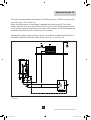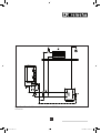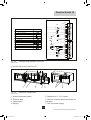
1
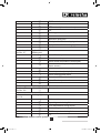
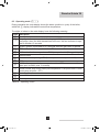
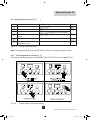
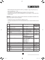
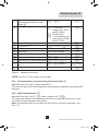
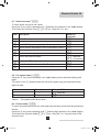
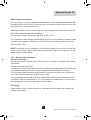
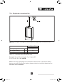
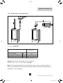
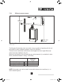
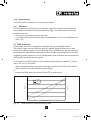
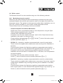
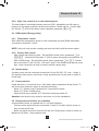
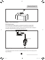
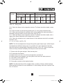
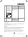
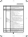
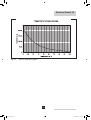
Remeha Quinta 30 Technical information Remeha Quinta 30 • High-efficiency condensing boiler for wall mounted installation • Output: 5.6 - 28 kW 1 57117.indd 1 1-4-2009 14:35:28 Remeha Quinta 30 TABLE OF CONTENT Preface 5 1 General description of the boiler 6 2 Construction 2.1 Boiler layout 2.2 Operating principle 7 7 8 3 Technical data and dimensions 3.1 Dimensions 3.2 Technical data 3.3 General Specification 9 9 10 11 4 Efficiency information 4.1 Annual efficiency 4.2 Heat to water efficiency 12 12 12 5 Application information 12 6 Control and safety equipment 6.1 The control panel 6.1.1 General 6.1.2 Layout of the control panel 6.1.3 Combined key functions (in operating mode only) 6.1.4 Display of values with more than two digits 6.2 Flow diagram control system 6.3 Operating mode (x[[) 6.4 Shut-off mode (bXX) 6.5 Setting mode user level (X[[) 6.5.1 Flow temperature set point (!) 6.5.2 Pump run on time HTG (@) 6.5.3 DHW temperature set point (3) 6.5.4 Boiler control setting (A) 6.6 Setting mode service level (X00) 6.6.1 Flow temperature set point during forced part load ($) 6.6.2 High limit thermostat (%) 6.6.3 Fan speed at full load HTG (^) 6.6.4 Fan speed at part load (HTG and DHW - &) 12 12 12 13 14 15 16 18 19 20 20 21 21 21 22 24 24 24 25 2 57117.indd 2 1-4-2009 14:35:49 6.7 6.8 6.9 7 6.6.5 Starting point modulation (*) 6.6.6 Interface selection (() 6.6.7 DHW cut-in temperature (B) 6.6.8 Fan Speed at DHW full load (C) 6.6.9 Forced part load time after start (HTG only - G) 6.6.10 DHW control stop set point (I) 6.6.11 DHW control option (J) 6.6.12 HTG cut in temp (N) 6.6.13 Boiler type (P) 6.6.14 Maximum delay time (U) 6.6.15 Start and end point analog signal (Q and Y) Read-out mode (X00) Fan speed mode (<00) Failure mode (x00) 25 25 25 26 26 26 26 27 27 27 27 28 28 28 Installation instructions 7.1 General 7.2 Location 7.3 Flue gas discharge and air supply 7.3.1 General 7.3.2 Classification due to discharging flue gases 7.3.3 Material and installation 7.3.4 Single boiler conventional flue 7.3.5 Single boiler, room sealed flue 7.3.6 Different pressure zones 7.3.7 Modular installations 7.4 Hydraulic installation 7.4.1 Condensate and AAV discharge 7.4.2 Water treatment 7.4.3 Cold feed and expansion tank height for open vented systems 7.4.4 Safety valve 7.4.5 Gas connection 7.4.6 System pump 7.4.7 Waterflow 7.5 DHW production 29 29 29 30 30 31 32 33 34 35 36 36 36 36 38 38 38 38 39 39 3 57117.indd 3 1-4-2009 14:35:49 Remeha Quinta 30 8 Electrical installation 8.1 General 8.2 Specifications 8.2.1 Electrical supply 8.2.2 Control box 8.2.3 Fuse specification 8.2.4 Boiler temperature control 8.2.5 High limit temperature protection 8.2.6 Low-water protection (flow and content) 8.3 External connections 8.4 Boiler control 8.4.1 Modulating (two wire control) 8.4.2 Analog control (0-10 Volt dc) 8.4.3 On / off control (1 x no volt switched pair) 8.4.4 High / low control (2 x no volt switched pairs) 8.5 DHW control (Broag priority) 8.5.1 Temperature control 8.5.2 Primary flow control 8.6 System pump 8.7 Frost protection 8.8 Remote alarm and boiler run indication 8.9 Safety interlock 42 42 42 42 42 42 43 43 43 43 45 45 47 47 48 48 48 48 48 48 48 49 9 Commissioning 9.1 Initial lighting 9.2 Shut-down 9.2.1 Temporary shut-down with frost protection 9.2.2 Permanent shut-down without frost protection 49 49 52 52 52 10 Fault-finding 10.1 General (all installations) 10.2 Fault codes 52 52 53 11 Inspection and servicing instructions 11.1 General 11.2 Annual Inspection 11.3 Maintenance 58 58 58 59 4 57117.indd 4 1-4-2009 14:35:49 PREFACE These technical instructions contain useful and important information for the correct operation and maintenance of the Remeha HTG boiler, model Quinta 30. Read these instructions carefully before putting the boiler into operation, familiarise yourself with it’s control functions and operation, strictly observing the instructions given. Failure to do so may invalidate warranty or prevent the boiler from operating. The installation and commissioning of the boiler must be carried out by a competent Engineer, with the relevant certification ie: CORGI, ACOPS, IEE regs. etc. On completion a copy of the commissioning sheet should be returned to Broag Ltd for record purposes. If you have any questions, or if you need more information about specific subjects relating to this boiler, or it’s installation please do not hesitate to contact us. The data published in these technical instructions is based on the latest information (at date of publication) and may be subject to revisions. We reserve the right to continuous development in both design and manufacture, therefore any changes to the technology employed may not be retrospective nor may we be obliged to adjust earlier supplies accordingly. 5 57117.indd 5 1-4-2009 14:35:49 Remeha Quinta 30 1 GENERAL DESCRIPTION OF THE BOILER The Remeha Quinta 30 is a wall hung condensing boiler which may be also installed free standing on a suitable frame (option). The one piece cast aluminium heat exchanger and other major components are contained within a sealed air box. This forms the main boiler casing with a removable front section for maintenance purposes. All electrical and electronic controls are contained within the instrument panel mounted behind the drop down lower front panel. The combined flue gas outlet and combustion air inlet are mounted on the top of the boiler with the flow, return, gas and condensate connections located at the bottom. The boiler is suitable for room sealed or open flue applications and has been designed for central heating and indirect hot water production at working pressures not exceeding 3 bar. It must be installed on a fully pumped system and is suitable for use on both sealed and open vented installations (minimum operating pressure of 0.8 bar). The pre-mix, down firing gas burner (NG or PROPANE) with its gas/air ratio control system ensures clean, trouble free operation with higher than average efficiencies of 109.3 % (NCV) in the condensing mode combined with ultra low NOx and minimum CO emissions. The standard control package allows actual and set values to be read and adjusted on the built in digital display which also provides normal operating and fault code indication. An intelligent, advanced boiler control (‘abc’) continuously monitors the boiler conditions, varying the heat output to suit the system load. The control is able to react to external “negative” influences in the rest of the system (flow rates, air / gas supply problems) maintaining boiler output for as long as possible without resorting to a lock out condition. At worst the boiler will reduce it’s output and/or shut down (shut-off mode) awaiting the “negative” conditions to return to normal before re-starting. The ‘abc’ control cannot override the standard flame safety controls. The boiler meets the requirements of the EC regulations and directives: - 90/396EEC Gas appliances directive - 92/42/EEC Efficiency directive - 73/23/EEC Electrical low voltage directive - 89/336/EEC E.M.C. directive Remeha Quinta 30 - PIN: 0063BM3043 6 57117.indd 6 1-4-2009 14:35:49 2 CONSTRUCTION 2.1 Boiler layout 11 11 12 1 12 1 13 13 14 15 16 2 3 4 3 4 5 6 5 6 7 7 2 1 0 8 bar 3 4 14 15 16 2 17 18 19 2 1 0 8 9 10 9 10 bar 3 4 17 18 20 Fig. 01 Boiler layout Remeha Quinta 30 and boiler layout with optional 3-way valve 04.W3H.79.00003 + 04.W3H.79.00011 Air supply fan. Pre-mix burner Combined ignition/ionisation probe Sight glass Gas combi-block (with governor) Cast aluminium heat exchanger Temperature sensor-return Facility for incorporating a rematic® weather compensated boiler control 9. Siphon 10. Hoses automatic air vent and condensate 11. Flue gas measure point 12. Automatic air vent 13. Gas injector/venturi 14. Temperature sensor-flow 15. Air inlet tube 16. Heat exchanger inspection cover 17. Pressure gauge 18. Control panel 19. Optional 3-way valve 20. DHW primary flow connection (when optional 3-way valve is fitted) 1. 2. 3. 4. 5. 6. 7. 8. 57117.indd 7 7 1-4-2009 14:35:49 Remeha Quinta 30 2.2 Operating principle Combustion air is drawn into the closed air box by a variable speed fan, through the air inlet connection from the plant room (open flued) or from outside via the concentric flue system (room sealed). On the inlet side of the fan is a specially designed venturi which is connected to the outlet side of the gas combi block. Depending on the demand (under the dictates of flow/return sensor and other external/ internal control inputs) the electronic control unit directly monitors the volume of gas and air being delivered to the premix burner. This mixture is initially ignited by the combined ignition/ionisation probe which then monitors the state of the flame. Should the flame not ignite or is unstable within the pre-set safety time cycle the controls will shut the boiler down (after 5 attempts) requiring manual intervention to reset the boiler. The digital display will also indicate a flashing fault code confirming the reason for the failure. The products of combustion in the form of hot flue gases are forced through the heat exchanger transfering their heat to the system water (the flue gas temperature is reduced to approximately 5°C above the temperature of the system return water) then discharged via the condensate collector, vertically through the 80/125 mm combined flue/air connection to atmosphere. Because of the low flue gas exit temperature there will be a vapour cloud formed at the flue gas terminal - this is not smoke, simply water vapour formed during the combustion process. If the controls allow the flow and therefore return temperature to fall below dew point (55°C) this water vapour will begin to condense out in the boiler, transfering it’s latent heat into the system water, increasing the output of the boiler without increasing the gas consumption. Condensation formed within the boiler and flue system is discharged from the boiler to an external drain via the drain pan / siphon supplied. 8 57117.indd 8 1-4-2009 14:35:49 3 TECHNICAL DATA AND DIMENSIONS 3.1 Dimensions Fig. 02 Dimensions Remeha Quinta 30 04.W3H.79.00010 + 04.W3H.79.00013 Return connection 22 mm Ø (m) DHW primary flow connection 22 mm Ø (m) (when optional 3-way valve is fitted) Flow connection 22 mm Ø (m) Gas connection 15 mm Ø (m) Condensate connection 25 mm Ø o/d (plastic) Combustion air supply connection 125 mm Ø i/d Flue gas connection 80 mm Ø i/d Holes for mounting bracket Hose automatic air vent 8 mm Ø o/d (silicone) 9 57117.indd 9 1-4-2009 14:35:49 Remeha Quinta 30 3.2 Technical data Boiler type General Colour side and front casing Colour instrument panel flap Boiler control options (External input) (Two wire control) Nominal output (80/60ºC) Nominal output (40/30ºC) Nominal input (GCV / Hs) Nominal input (NCV / Hi) Weight dry Noise level at 1 m from boiler Gas- and flue details Category Min/Max Inlet pressure natural gas Min/Max Inlet pressure propane Gas consumption (natural gas) Gas consumption (propane) NOx-emission NOx -emission (O2 = 0%, dry) Residual fan duty Mass flue rate Classification due to discharging flue gases Water side Maximum flow temperature Operating flow temperature Operating pressure min. (open vented) Operating pressure min. (pressurised) Operating pressure max. Water contents Water resistance at 11 °C Δt Water resistance at 20 °C Δt Nominal flow at 11 °C Δt Nominal flow at 20 °C Δt Quinta 30 BS RAL kW kW kW kW kg dB(A) mbar mbar m3/h 3 m /h mg/kWh ppm Pa kg/h ºC ºC bar bar bar ltr mbar mbar l/s l/s 9016 7036 On/off, High/low, Analog 0 -10V Communicating Modulation 5.6 – 28.0 5.9 – 29.6 6.3 – 31.6 5.7 – 28.5 43 < 44 II 2H3P 15 – 50 37 - 50 0.6 – 3.2 0.3 - 1.2 < 36 < 20.2 100 10 - 48 B23, B33, C13, C33, C43, C53, C63, C83 100 (110) 20 - 90 0.3 0.8 3.0 3.1 460 140 0.61 0.34 10 57117.indd 10 1-4-2009 14:35:49 Boiler type Electrical Main supply Electric rating without pump (max) Insulation class Table 01 Quinta 30 V/Hz W IP 230 / 50 46 20 Technical data remeha Quinta 30 3.3 General Specification (to be read with above table) - One piece cast aluminium heat exchanger - 22 mm Ø (m) flow and return connections - 15 mm Ø (m) gas connection - Maximum operating pressure of 3.0 bar - Maximum operating temperature of 95°C - Low NOx, < 20 ppm (O2 = 0%) - Pre-mix, fully modulating (20 -100%) gas burner with gas/air ratio control for maximum efficiency - Intelligent advanced boiler control ‘abc’ c/w a comprehensive operating, service and fault diagnostic facility - Available for conventional flue or room sealed operation - Capable of remote BMS (0 -10V, on/off and High/low control options) - Supplied fully factory assembled - Powder coated enamel steel casing - Suitable for use with a Natural gas or propane as standard (choices on commissioning) - Supplied as standard with safety shut-off facility, temperature indication, control and high limit sensors, common alarm and boiler run indication - Efficiency of 98% at 80/60 °C (Hi) - Max. efficiency of 109.3% (Hi) in fully condensing mode - Manufactured to ISO 9001 - CE approved 11 57117.indd 11 1-4-2009 14:35:49 Remeha Quinta 30 4 EFFICIENCY INFORMATION 4.1 Annual efficiency 108.8% at Hi at an input of 30% and a return temperature of 30°C. 4.2 Heat to water efficiency a. Up to 98% at Hi at an average water temperature of 70°C (80/60°C). b. Up to 108.8% at Hi at an average water temperature of 35°C (40/30°C). Note: NCV = Hi, GCV = Hs 5 APPLICATION INFORMATION The Quinta 30 can be used on all new and re-furbishment projects in both single and multiple configurations. Conventional and room sealed flue system capability means that the boiler can be sited almost anywhere within a building. The Remeha range of weather compensators (options) are able to communicate directly with the boiler controls (two wire) to make full use of it’s fully modulating feature, ensuring that the boiler closely matches the system demand at all times. External control systems (BMS) can be interfaced with the boiler to provide on/off - high/low or modulating (0 -10V) control options. 6 CONTROL AND SAFETY EQUIPMENT 6.1 The control panel 6.1.1 General The boiler is supplied with a standard set of defaults pre-programmed for normal operation but can be tailored by the Engineer to suit most site conditions. These values are set and read using the built in control panel or with a notebook computer (with the correct software). For security the control has three levels of access: - User level - free access - Service level - access with service code by qualified personnel - Factory level - access by PC with factory code (Remeha only) 12 57117.indd 12 1-4-2009 14:35:50 6.1.2 Layout of the control panel Fig. 03 Control panel 00.W4H.79.00044 a. ‘code’-display Indicates on user level: operating mode: only one digit 1 setting mode: digit with dot ! read-out mode: digit with flashing dot ! shut-off mode: letter b forced full load: letter h forced part load: letter l Additional indication on service level: b. t-display Indicates: c. reset-key: d. ‘m’ -key: speed mode: alternate half digit < failure mode: flashing digit 1 Temperatures, settings, fault codes (flashing digits), shut-off codes (flashing dots) to reset after a lockout condition Program function: key to select the required mode e. ‘s’-key: Program function: key to select the required program within the selected mode e. ‘s’-key + r-symbol: Switch function: burner switch HTG (manual override) f. ‘e’-key: Program function: key to save the settings f. e-key + k-symbol: g. [+]-key: Switch function: burner switch DHW (manual override) g. [+]-key + q-symbol: h. [-]-key: h. [-]- key+ h-symbol: Program function: to select a higher setting Switch function: pump manual override Program function: to select a lower setting Switch function: manual override (hand/auto) Table 02 Control panel functions 57117.indd 13 13 1-4-2009 14:35:50 Remeha Quinta 30 6.1.3 Combined key functions (in operating mode only) When the boiler is in the operating mode, keys with the illuminated symbols above have a double function (Program and Switch). To use them for a Program function press the key once - and for a Switch function (either on or off) press the key and hold for 2 secs. The status of the switch function will be confirmed by the illuminated symbol as follows: ‘s‘-key and r-symbol: - (symbol) not illuminated: HTG under normal control - red (symbol) on: HTG off (manual override) ‘e’-key and k-symbol: - (symbol) not illuminated: DHW under normal control - red (symbol) on: DHW off (manual override) [+]-key and q-symbol: - green (symbol) on: continuous pump operation - (symbol) not illuminated: pump under boiler control [-]-key and h-symbol: - green (symbol) on: HTG on (manual override) - (symbol) not illuminated: HTG under normal control NOTE: In the Switch function, (in order to protect the boiler and the installation) the flow temperature cannot exceed it’s pre-set maximum. It is also not possible to change any parameters. Forced mode ‘high’ (h[[) By pressing the ‘m’ and [+]-key simultaneously in operating mode, the boiler will burn at maximum power. The letter h will now appear on the display. By pressing the [+] and [-]-keys simultaneously, the boiler will return to operating mode. Following a manual override the boiler will return to normal (auto control) if no keys are used within a 15 minute period Forced mode ‘low’ (l[[) By pressing the ‘m’ and [-]-key simultaneously in operating mode, the boiler will burn at minimum power. The letter l will now appear on the display. 14 57117.indd 14 1-4-2009 14:35:50 By pressing the [+]and [-]-keys simultaneously, the boiler will return to operating mode. Following a manual override the boiler will return to normal (auto control) if no keys are used within a 15 minute period. 6.1.4 Display of values with more than two digits The display has only two digits available therefore values over this are displayed as follows : - negative values will be indicated by a dot behind the last digit e.g. 1) = -10 - values from 00 to 99 will be indicated without any punctuation marks - values from 100 to 199 will be indicated by a dot between both digits e.g. )0 = 100, !0 = 110, (9 = 199. - values from 200 to 299 will be indicated by a dot behind every digit e.g. )) = for 200, !) = 210, (( = 299. 15 57117.indd 15 1-4-2009 14:35:50 Remeha Quinta 30 6.2 Flow diagram control system press the ‘m’ -key press the ‘s’-key ‘code’-display Operating mode, see Par. 6.3 only digit or letter 0 - 9,h,l,b Setting mode, user level, see Par. 6.5 Setting mode, service level, see Par. 6.6 tdisplay Flow temperature or shut-off code digit or letter with dot ! Flow temperature set point @ Pump run on time HTG # DHW temperature set point A Boiler control setting n/a u service engineer level only: % Flow temperature set point during forced part load High limit temperature set point ^ Fan speed at full load (HTG) & Fan speed at part load (HTG and DHW) $ * Modulation start point Δt (F/R) ( Interface selection (control option) B DHW cut-in Δt C Fan speed at full load (DHW) D intern E n/a F n/a G Forced part load time after start (HTG) H Fan speed at start I DHW control stop or boiler modulation set point (based on parameter #) 16 57117.indd 16 1-4-2009 14:35:50 Read-out mode, see Par. 6.7 J DHW control mode L n/a N HTG cut in Δt (based on return) O n/a P Boiler type T intern U Maximum delay time Q Start point for 0 Volt analog signal Y End point for 10 Volt analog signal _ digit or letter with flashing dot intern ! Actual flow temperature @ Actual return temperature # Actual DHW temperature (with sensor) $ % Actual outdoor temperature (with Chronotherm sensor) n/a ^ Flow temperature (set point) & Actual heat demand status * Calculated HTG cut-in temperature ( Actual flow temperature rise n/a A service engineer level only: Speed mode, alternate half digit Fan speed see Par. 6.8 < Failure mode, see flashing digit Par. 6.9 1 Failure code 2 Operating code during failure 3 Flow temperature during failure 4 Return temperature during failure 5 DHW temperature during failure n/a 6 Table 03 Flow diagram control system 17 57117.indd 17 1-4-2009 14:35:50 Remeha Quinta 30 6.3 Operating mode (x[[) During operation the code-display shows the status (position in cycle) of the boiler, whilst the t-display indicates the actual flow temperature. The digits or letters in the code-display have the following meaning: Code Description 0 Standby: there is no heat demand from control system. 2 Pre-purge: before start-up, the boiler is purged for 3 seconds. Post-purge: when the heat demand has been met, the fan continues to operate for another 10 seconds. Ignition: ignition is activated for 2.4 seconds while the gas valve is opened. 3 HTG mode; the boiler operates in the HTG mode. 4 DHW mode: the three way valve or DHW pump activated (Broag priority only) 5 Internal check 6 Normal control stop during HTG (flow temperature > set point + 5 °C) 7 HTG pump run on 8 b DHW pump run on or for three way valve option, HTG pump run on with valve open to DHW (max. 5 minutes) Normal control stop during DHW (flow temperature > set point DHW + DHW control stop set point + 5°C) Shut-off mode h Forced full load. l Forced part load. 1 9 Table 04 Operating codes 18 57117.indd 18 1-4-2009 14:35:50 6.4 Shut-off mode (bXX) During shut-off mode condition the code-display will show a b, whilst the t-display indicates the cause with two flashing dots. Table below details cause of shut-off mode. Code B@% b@^ B@* B@( B#) B$# Description Maximum acceptable flow temperature rise exceeded. The boiler will shut off for ten minutes, then restart. Should the flow temperature conditions remain the same after 5 attempts, this code will be recorded as a shutdown failure. Boiler will not lockout. Contacts of the external interlock have opened during heat demand. The boiler will shut off for 120 seconds. Should the contacts close again during heat demand, the boiler will wait the remaining time from the 120 seconds before attempting a restart. Internal check on fan speed. After 5 attempts, the boiler will lockout. This code will be recorded. Internal check on fan speed. After 5 attempts, the boiler will lockout. This code will be recorded. Maximum temperature difference between flow and return exceeded. The boiler will shut off for 150 seconds, then restart. Should the temperature difference conditions remain the same after 10 attempts, this code will be recorded as a shut-down failure. Boiler will not lockout. One or several adjusted parameters out of range including some factory defaults which should not have been changed. Check and reset parameters: - Press the ‘reset’-key imidiately followed by pressing the ‘m’-key for about 12 sec - ‘code’- display shows P - Use [+] and [-]-keys to enter correct boiler parameter ( P=74) - Press ‘e’-key to confirm settings Table 05 Shut-off codes NOTE: Shut-off mode is a normal boiler operating function and does not represent a boiler failure. However, this may indicate a system problem, an internal boiler check or an incorrect parameter setting. 19 57117.indd 19 1-4-2009 14:35:50 Remeha Quinta 30 6.5 Setting mode user level (X Code ! @ ) Description Setting range Flow temperature set point 20–90 ºC Pump run on time HTG 00 = pump run on 10 seconds Preset 80 03 01–15= pump run on in minutes # A u DHW temperature set point Boiler control setting Base point internal compensation slope 20–75 °C (only with sensor) 55 Control mode (modulating-on/off etc.) 11 n/a 20 Table 06 Setting mode user level Note: Changing code @ and code A should only be on design engineers advice 6.5.1 Flow temperature set point (!) The required flow temperature is adjustable from 20 to 90°C (factory default 80°C). Fig. 04 Typical setting change procedure 20 57117.indd 20 1-4-2009 14:35:50 6.5.2 Pump run on time HTG (@) Pump run on time can be adjusted (Please refer to installation contractor) - Press the ‘m’ -key until the digit ! (with dot) appears in the ‘code’-display. - Press the ‘s’-key until the digit @ (with dot) appears in the ‘code’-display. - Set the required value, using the [+] and [-]-keys. - Press the ‘e’-key to store the new value (value will flash twice). - Press the ‘reset’-key to return to operating mode. NOTE: For continuous pump operation use manual override, see Par. 6.1.3. Code t Description @ 00 Pump runs on for 10 seconds @ Xx Pump runs on for 1 to 15 minutes (xx = 01 to 15) Table 07 Pump run on time HTG 6.5.3 DHW temperature set point (3) The DHW temperature is adjustable from 20 to 75°C (factory default 55°C). Only with Broag DHW priority sensor. - Press the ‘m’ -key until the digit ! (with dot) appears in the ‘code’-display. - Press the ‘s’-key until the digit # (with dot) appears in the ‘code’-display. - Set the required value, using the [+] and [-]-keys. - Press the ‘e’-key to store the new value (value will flash twice). - Press the ‘reset’-key to return to operating mode. REMARK: there are further adjustments available on service level. Please refer to your service engineer or contractor (see Par. 6.6.7). 6.5.4 Boiler control setting (A) The boiler is factory set to option 11 (HTG modulating or on/off with DHW on) To change the control option: - Press the ‘m’ -key until the digit ! (with dot) appears in the ‘code’-display. - Press the ‘s’-key until the digit A (with dot) appears in the ‘code’-display. - Set the required X and Y values as listed below in using the [+] and [-]-keys. - Press the ‘e’-key to store the new value (value will flash twice). - Press the ‘reset’-key to return to operating mode 21 57117.indd 21 1-4-2009 14:35:50 Remeha Quinta 30 With the ‘code’- display showing A - the t-display will indicate the method of boiler control in the first segment x[and the option to turn the HTG and DHW on or off in the second segment [y. By using codes from the table below a series of control options are available Example: xy 11 - Boiler enabled internal modulation with booster on * - HTG and DHW on (as default) 42 - Analog signal 0 -10V on temperature - HTG on and DHW off 23 - Boiler high/low - HTG off and DHW on t-display Description First segment x[ Boiler control option 1 Boiler enabled internal modulation with booster on * 2 Boiler high/low 3 Boiler enabled internal modulation with booster off * 4 Analog signal 0-10V on temperature 5 Analog signal 0-10V on output % t-display Description Second segment [y Operation mode 0 HTG and DHW off 1 HTG and DHW on 2 HTG on and DHW off 3 HTG off and DHW on Table 08 Boiler control option * NOTE: Booster function n/a in UK 6.6 Setting mode service level (X00) (only for the qualified service engineer) To prevent accidental, unauthorised access by non-qualified persons the control system requires an input code to gain access to the second level of boiler control. - Press the ‘m’ - and ‘s’-keys simultaneously and hold. The ‘code’-display now shows a letter c with a random number in the t-display. 22 57117.indd 22 1-4-2009 14:35:51 - While holding both keys pressed, set the t-display to 12, using the [+] or [-]keys and press the ‘e’-key. - The display will flash twice confirming acceptance of the access code. - Release the keys and c12 will dissappear from the display. You are now in the service mode WARNING: changing factory defaults without reference to the tables contained in this manual may result in incorrect operation. - To delete the service code press the ‘reset’-key once - If no keys are pressed over a 15 minute period the service code will delete automatically Code Description $ % ^ & * ( Setting range Flow temperature set point during 20 - 90ºC forced part load High limit temperature set point 90 – !0 (= 110°C) Fan speed at full load (HTG) 10 – 60 hundreds Fan speed at part load (HTG and 10 – 60 hundreds DHW) Modulation start point ΔT (F/R) 05 - 30 ºC Interface selection (control option) 00 internal (Chronotherm control only) Preset Q30 80 )0 (=100)* 48 12 25 01 01 external interface B DHW cut-in ΔT 10 06 07 08 C Fan speed at full load (DHW) D Intern 10 – 60 hundreds May not be changed! E N/a )0 (=100)* F N/a 25 G Forced part load time after start (HTG) Fan speed at start H – 05 read 1 - 5 °C read 10 °C read 15 °C read 20 °C 05 48 00 00 – 15 minutes 03 May not be changed! 25 23 57117.indd 23 1-4-2009 14:35:51 Remeha Quinta 30 L DHW control stop or boiler modu- 00 – 30 °C lation set point (based on parameter #) DHW control option 00 = Three way valve(port A = HTG, port B = DHW) 01 = DHW pump 02 = inverted three way valve (port A = DHW, port B = HTG) Variable speed pump n/a I J 20 00 )3 N HTG cut in ΔT O N/a P Boiler type May not be changed! 74 T Intern May not be changed! 01 U Maximum delay time Q Y _ 1) (= -10°C) – 20 °C 03 10 00 – 99 minutes Start point for 0 Volt analog signal 5) (= -50) – 50 °C End point for 10 Volt analog sig- 50 – (( (=299) °C nal Intern 15 00 )0 (=100)* 10 Table 09 Settings service level *NOTE: see Par. 6.1.4 for values over two digits 6.6.1 Flow temperature set point during forced part load ($) Adjustable from 20 to 90°C, factory default 80°C This value will prevent the flow temperature exceeding this temperature during the part load time. 6.6.2 High limit thermostat (%) Adjustable from 90 to 110°C (!0), factory default 100°C ()0). This value sets the high limit temperature at which the boiler will shut down in a lock out condition requiring manual intervention. Note: this parameter will have an effect on the minimum flow rate requirement, see Par. 7.4.7. 24 57117.indd 24 1-4-2009 14:35:51 6.6.3 Fan speed at full load HTG (^) Adjustable from 20% to 100% output (= 1200 to 5300 rpm), factory default 48 (100%). This value sets the maximum output of the boiler. 6.6.4 Fan speed at part load (HTG and DHW - &) Adjustable from 20% to 100% output (= 1200 to 5300 rpm), factory default 12 (20% output). This value sets the minimum output of the boiler. 6.6.5 Starting point modulation (*) Adjustable from 5 to 30°C, factory default 25°C. This value sets the flow/return ΔT point at which the control modulation begins. If the Δt continues to rise, at 40°C the boiler will be at minimum output (parameter &), at 30°C the boiler will shut off (code b#), see Par. 6.4). The factory default should be correct for most installations. Changing this value should only be carried out on advice from the service engineer. NOTE: Installations with low flow problems would benefit by reducing this set point to force modulation to begin sooner and minimise boiler off time. 6.6.6 Interface selection (() Adjustable 00 or 01, factory default 01 This value sets the control option. 01 for standard 0 -10 Volt external control and rematic® series of compensators (if fitted). 00 for the Honeywell Chronotherm option. 6.6.7 DHW cut-in temperature (B) Adjustable from 01 to 20 °C (8 steps, see Table 09), factory default 5°C (05). DHW demand: With sensor: - The DHW demand is satisfied when the DHW temperature equals the DHW set point temp (parameter #) + 5°C. - The DHW cut-in temperature sets the Δt below this end point for DHW demand. Cut-in temperature = DHW set point (55) + 5 - parameter B (5) i.e. 55 + 5 - 5 = 55°C. With thermostat or rematic® control: the thermostat or rematic® control determines the DHW demand. 25 57117.indd 25 1-4-2009 14:35:51 Remeha Quinta 30 Boiler modulation during continuing DHW demand Sensor, thermostat and rematic® control: - The boiler will modulate when the flow temp equals the DHW set point + DHW control stop set point (parameter I) i.e. 55+20 = 75. - The boiler carries out a control stop at a flow temp of 80°C (modulation point + 5°C), the display initally shows 980, reducing to 975. - The DHW cut-in temperature sets the Δt below this control stop. Cut-in temperature = DHW set point (55) + DHW control stop set point (parameter I) + 5 - parameter B (5) i.e. 55 +20 + 5 - 5 = 75 6.6.8 Fan Speed at DHW full load (C) Adjustable from 20% to 100% output (= 1200 to 5300 rpm), factory default 53 (100%). This value sets the maximum output of the boiler. Parameters D - E - and F are factory set and must not be changed 6.6.9 Forced part load time after start (HTG only - G) Adjustable from 00 - 15 min., factory default 03 (3 minutes). This value sets the period of time the boiler will stay on part load at start up during which time the flow temp is limited by part load temp set point (parameter $) Changing the factory default should only be carried out on advice from the service engineer. NOTE: When using an external analog (0 -10V) or 2 wire modulation input, the factory default 03should be changed to 00. Parameter H factory set must not be changed 6.6.10 DHW control stop set point (I) Adjustable from 00 - 30 °C factory default 20°C. Refer to Par. 6.6.7. 6.6.11 DHW control option (J) Three options 00 - 01 - 02 factory default 00. This value sets the DHW control option. 00 Three way diverting valve (port A - HTG and Port B - DHW) 01 DHW pump 02 Inverted three way diverting valve (port B - HTG and Port A - DHW) 26 57117.indd 26 1-4-2009 14:35:51 Parameter L not applicable 6.6.12 HTG cut in temp (N) Adjustable 1) (-10) to 20 °C, factory default 03. This value sets the Δt below actual return temp at the moment of control stop during HTG demand. A control stop occurs when the flow temp equals the flow temp set point + 5°C. HTG cut in temperature = actual return temperature at the moment of control stop (e.g. 60) - parameter N (3) ie 60 - 3 = 57°C If this takes longer than the maximum delay time (parameter U), the boiler will restart (unless flow temperature exceeds flow temperature setpoint). Parameter O not applicable 6.6.13 Boiler type (P) Factory default 74 must not be changed. Parameter T factory set must not be changed. 6.6.14 Maximum delay time (U) Adjustable from 00 - 99 minutes, factory default 15 minutes (15). This value sets the maximum off time following a control stop. The minimum off time is preset to a fixed value (150 sec.). A combination of both values is used to prevent hunting taking place. 6.6.15 Start and end point analog signal (Q and Y) Start point (0 Volt): adjustable between 5) (-50)°C and +50°C, factory default 00°C. This value sets the required flow temp at 0 Volt signal input (restricted by the min flow set point). End point (10 Volt): adjustable between +51°C and (( (+299)°C, factory default )0 (100)°C. This value sets the required flow temp at 10 Volt signal input (restricted by the max flow set point). NOTE: These settings are only applicable when boiler control operation parameter (A) has the x value set to 4. 27 57117.indd 27 1-4-2009 14:35:51 Remeha Quinta 30 6.7 Read-out mode (X00) To check boiler set points and values. Using the ‘m’-key, press repeatedly until !(flashing dot) appears in the ‘code’-display. Then select the required code @, # or $ etc. using the ‘s’-key. Code Description Read-out (example) ! Actual flow temperature 80 @ Actual return temperature 70 # Actual DHW temperature (only with sensor) 58 $ Actual outdoor temperature (with Chronotherm sensor) 05 % n/a 3& ^ Flow temperature (set point) 80 & Actual heat demand status 1x = demand; 0x = no demand * Calculated HTG cut-in temperature 67 ( Actual flow temperature rise [0.1 °C/sec] 02 A n/a Table 10 Read-out mode user level 6.8 Fan speed mode (<00) Using the ‘m’ -key, press repeatedly until ‘code’-display shows alternate flashing half digits. The value in the t-display shows the actual fan speed using two alternate double digits as table: Code , Description Fan speed Example 5250 r/m 52 hundreds > Fan speed 50 units Table 11 Fan speed mode service level 6.9 Failure mode (x00) To check the latest failure with the accompanying operating codes and relevant temperatures. Using the ‘m’ -key, press repeatedly until 1 (flashing digit) appears in the ‘code’-display. Then select the required code 2, 3 or 4 etc. using the ‘s’-key and read off the relevant value. 28 57117.indd 28 1-4-2009 14:35:51 Code t Description 1 37 Display of failure code (see Par. 10.2) 2 03 Operating mode during failure 3 53 Flow temperature during failure 4 40 Return temperature during failure 5 60 DHW temperature during failure 6 3& n/a Table 12 Failure mode on service level Example as above: Failure code 37 indicates the return temperature sensor failed during HTG operation (03), at a flow temperature of 53°C, a return temperature of 40°C and DHW temperature of 60°C. 7 INSTALLATION INSTRUCTIONS 7.1 General All gas appliances must, by law, be installed by a competent qualified engineer registered with CORGI and holding the relevant qualifications and certificates (for example ACOPS and IEE regs.) The complete installation must comply with the current editions of relevant British Standards and codes of practice, including the latest local and national regulations for this type of equipment. Important: The Remeha Quinta 30 is a CE certified appliance and must not therefore be modified or installed in any way contrary to these “Installation and Maintenance Instructions”. These manufactures Instructions must NOT be taken as overriding statutory obligations. Failure to install this appliance correctly could result in an unsafe condition which can lead to prosecution. It is your own interest and that of safety to ensure that the law is comlied with. 7.2 Location The remeha Quinta 30 is primarily designed for wall mounting (on the bracket supplied). The wall should be flat, vertically plumb and capable of supporting the full weight of the boiler full of water. An optional floor frame can be used for a free standing installation or where the wall cannot carry the weight. 29 57117.indd 29 1-4-2009 14:35:51 Remeha Quinta 30 The following minimum clearances are required: - Front: 600 mm - Sides: 25 mm - Bottom: 250 mm - Top: 400 mm. Fig. 05 Minimum clearances around the boiler 05.W3H.79.00065 7.3 Flue gas discharge and air supply 7.3.1 General The Remeha Quinta 30 is suitable for conventional room ventilated or room sealed operation. Specify at the time of ordering if the boiler is to be installed for twin pipe room sealed operation. In that case, the boiler will be supplied with an adaptor plate (concentric to twin pipe). Before installing flue system, remove the transit cover plate. Fig. 06 Top view Remeha Quinta (standard concentric version with optional twin pipe adaptor shown right) 05. W3H.79.00077 + 00.W3H.79.00045 30 57117.indd 30 1-4-2009 14:35:51 Horizontal components in the flue gas discharge system should slope towards the boiler. Horizontal components in the air supply system should slope towards the supply opening. Care should be taken when siting flue exit positions as a vapour plume will be visible when the boiler is operational (flue gas temperature will be less than 75°C resulting in the water vapour condensing out on contact with the air). 7.3.2 Classification due to discharging flue gases Classification according to CE: Type B23: Conventional room ventilated boiler without draft diverter. Air supply from boiler room: flue gas discharge on roof. Type B33: Conventional room ventilated boiler without draft diverter, flue gas discharge is air enclosed. Type C13: Room sealed boiler, connected to combined wall outlet. Type C33: Room sealed boiler, connected to a combined roof outlet. Type C43: Room sealed boiler in cascade configuration, connected via two ducts to a common duct system serving more than one boiler. Type C53: Room sealed boiler, connected to separate ducts for the air supply and flue gas discharge, terminated in zones of different pressure. Type C63: Room sealed boiler, supplied without the terminal or the air supply and flue gas discharge ducts. Type C83: Room sealed boiler, connected via two ducts to a common duct system serving more than one boiler. (flue gas discharge always under pressure) Conventional open flue installation: Combustion air for the boiler must be provided to the room/compartment in accordance with the British Standards. For maximum flue length, see table in Par. 7.3.4. 31 57117.indd 31 1-4-2009 14:35:52 Remeha Quinta 30 Room sealed installations: It is unnecessary to provide separate combustion air to the room/compartment as this is supplied direct to the boiler via the concentric or eccentric system and the room sealed horizontal or vertical terminal unit. Additional ventilation will be required to the room/compartment in accordance with the British Standards (compartment ventilation). For maximum flue/air inlet length, see table in Par. 7.3.5. For installations where supply and discharge points are in two different pressure zones (eccentric only), please contact Broag Technical Dept. for further details and advice. See also Par. 7.3.6. NOTE: the boilers can be installed on a flue dilution system, but must have a total flue break to avoid boiler controls being affected by the flue dilution fan pressures. For full details please contact Broag. 7.3.3 Material and installation Flue gas discharge: Rigid single walled: stainless steel (316), aluminium or plastic (to comply with building regulations). Flexible: stainless steel (316). Construction: all joints and seams should be gastight and watertight with the horizontal runs graded towards the boiler to allow condensate free drainage to the boiler The flue outlet should terminate with reduction cone and bird guard only (chinamans hat or GLC type terminals etc. should not be used). Use vertical flue terminal MG 87973 for classification C33 and use horizontal flue terminal MG 87996 for classification C13. Flue material for classification C6 must comply EN 483 annex N and must always be in draft condition. Air supply: Single walled, rigid or flexible: aluminium, stainless steel and plastic (to comply with building regulations). 32 57117.indd 32 1-4-2009 14:35:52 7.3.4 Single boiler conventional flue Fig. 07 Flue gas discharge duct without bends, single boiler, conventional flue. 04.W3H.79.00004 max eq. Length L eq. Length bend 45° eq. Length bend 90° m m m Quinta 30 80 mm 40 1.2 4 Table 13 Calculation data conventional flue Example: Quinta 30, total length 15 m, 2 bends 90°. 15 m + 2 x 4 = 23 < 40: flue OK. Note: If the design parameters are outside the values shown in the above table or there is any doubt over the flue system, please contact our technical department for calculation to be undertaken. 33 57117.indd 33 1-4-2009 14:35:52 Remeha Quinta 30 7.3.5 Single boiler, room sealed flue Fig. 08 Flue gas discharge duct without bends, single boiler, room sealed application. 04.W3H.79.00005 + 04.W3H.79.00006 Quinta 30 80/125 mm max eq. Length m 20 eq. Length bend 45° m 1.2 eq. Length bend 90° m 4 Table 14 Calculation data room sealed applications Example: Quinta 30, total length 10 m, 2 bends 90°. 80 mm: 10 m + 2 x 4 = 18 m < 20 m: flue OK. Note: If the design parameters are outside the values shown in the above table or there is any doubt over the flue system, please contact our technical department for calculation to be undertaken. 34 57117.indd 34 1-4-2009 14:35:52 7.3.6 Different pressure zones Bird guard Flue outlet Air inlet Fig. 09 Different pressure zones 04.W3H.79.00008 The Remeha Quinta boiler (twin connection only) is capable of operating with the air inlet and flue outlet in different pressure zones (CLV System). There are some restrictions to the flue/air inlet lengths and max height differences which have been detailed in Fig. 09. Maximum total length of air inlet and flue gas outlet pipework (L) as detailed in table below (calculation based on using 1 x 90 bend). Quinta 30 80 mm max eq. Length m 20 eq. Length bend 45° m 1.2 eq. Length bend 90° m 4 Table 15 Calculation data different pressure zones NOTE: this system may not be used in areas with adverse wind conditions (i.e. in some coastal regions). 35 57117.indd 35 1-4-2009 14:35:52 Remeha Quinta 30 NOTE: If the design parameters are outside the values shown in the above table or there is any doubt over the flue system, please contact our technical department for calculation to be undertaken. 7.3.7 Modular installations For flue gas-side and air-side connections for multiple boilers in cascade configuration, refer to Broag for advice. 7.4 Hydraulic installation 7.4.1 Condensate and AAV discharge Discharge the condensate and AAV relief via a tundish, directly into a drain. Only use synthetic material for the connecting piping, because of the acidity (pH 2 - 5) and allow a min. of 30 mm per M to ensure a good flow rate. Fill the siphon with water before firing the boiler. It is not advisable to discharge into an outside gutter, because of the risk of freezing. 7.4.2 Water treatment The system should be filled with mains cold water (for the UK this will usually have a pH of between 7 and 8). Pressurised installations with a boiler/system content ratio of 1:10 or less should not require water treatment, provided that the following conditions apply: - The system is flushed thoroughly to remove all fluxes and debris and filled completely once. - Make up water is limited to 5% per annum. - The hardness of the water does not exceed 360 ppm (20°D). All scale deposits will reduce the efficiency of the boiler and should be prevented. However provided the above is complied with any scale produced will not be too detrimental to the boiler efficiency and will not reduce the anticipated life expectancy of the boiler. NOTE: Scale deposits in excess of 5 mm will reduce boiler efficiency and increase the risk of premature casting failure. 36 57117.indd 36 1-4-2009 14:35:52 As most systems contain a variety of metals, it is considered good practice to provide some form of water treatment (especially in open vented systems) in order to prevent or reduce the following. - Metallic corrosion - Formation of scale and sludge - Microbiological contamination - Chemical changes in the untreated system water Suitable chemicals and their use should be discussed with a specialist water treatment company prior to carrying out any work (environmental aspects, health aspects). The specification of the system and manufacturers recommendations must be taken into account, along with the age and condition of the system. New systems should be flushed thoroughly to remove all traces of flux, debris, grease and metal swarf generated during installation. Care to be taken with old systems to ensure any black metallic iron oxide sludge and other corrosive residues are removed, again by thoroughly flushing, ensuring that the system is drained completely from all low points. NOTE: Please ensure that the new boiler plant is not in circuit when the flushing takes place, especially if cleansing chemicals are used to assist the process. IMPORTANT: Under no circumstances is the boiler to be operated with cleaning chemicals in the system. To Summarise: - Minimise water loss - Prevent pumping over in open vented systems - Provide adequate air venting at all high points - Maximum chlorine content of 200 mg/l Take advice on the suitability of inhibitors for use with aluminium MAX pH of 8.5 when using additives (max. pH of 9 without additives) 37 57117.indd 37 1-4-2009 14:35:52 Remeha Quinta 30 If water treatment is used, we recommend the following products: ‘Copal®’ manufactured by: Fernox, Cookson Electronics Forsyth Road Sheerwater Woking Surrey GU21 5RZ Tel No: 01483 793200 Fax No: 01483 793201 Email: [email protected] Web site: www.fernox.com or: Sentinal ‘X100®’ manufactured by: BetzDearborn Ltd Sentinal Foundry Lane Widnes Cheshire WA8 8UD Tel No: 0151 424 5351 Fax No: 0151 420 5447 For the correct dosage and for further information on water treatment or system cleaning we advise direct contact with either of the above companies. 7.4.3 Cold feed and expansion tank height for open vented systems We recommend the boiler is installed on a closed (pressurised) system wherever possible with a minimum operating pressure of 0.8 bar. However, open vented systems can be accomodated as follows: The cold feed and expansion tank heights for all open vented systems must comply with the requirements laid down in the Health and Safety Executive publication (latest execution). The Remeha Quinta series boilers require a minimum static head of 3 m. 7.4.4 Safety valve A safety valve should be fitted in accordance with the British Standards. Recommended minimum size of 15 mm (full bore type). 7.4.5 Gas connection Connect the boiler to the incoming gas in accordance with the requirements of the Gas supply company. Install the main gas cock near the boiler. The gas connection is located at the bottom of the boiler. Fit a gas filter in the gas supply piping to avoid debris in the gas control unit. NOTE: The boiler is suitable for both natural gas and propane firing. It is supplied as standard set for natural gas, therefore an adjustment to the gas valve and the fan speed setting must be carried out BEFORE the boiler is fired and commissioned for the first time on propane (ref. Par. 9.1). 38 57117.indd 38 1-4-2009 14:35:52 7.4.6 System pump The boiler must be installed on a fully pumped system. 7.4.7 Waterflow The Quinta series of boilers have no minimum water flow requirement provided the factory default modulation start point (parameter *) is not raised and the following conditions are met: - the two wire modulating controls are used, - on a pressurised system with the high limit temperature set to flow temperature set point + 20. 7.5 DHW production The Remeha Quinta 30 is supplied as standard with an inbuilt DHW control. This control, when used in conjuction with the optional Broag DHW sensor or thermostat (not a Broag supply), a 3-way diverting valve or DHW pump, can provide boosted primary flow temperature independent of the variable temperature flow for the fully condensing mode. However it can be independantly time controlled and will isolate the HTG system during the demand period. On demand of the DHW sensor or thermostat and depending on parameter J (reference: Par. 6.6.11), the boiler: - either operates the three way valve diverting flow water from HTG to the calorifier (Note: please refer to the resistance graph below) or - powers the DHW pump and turns off the HTG or boiler pump. 120 3000 100 2500 dP (mBar) 80 2000 60 1500 40 1000 20 500 0 Flow (l/h) dP (mBar) Flow (l/h) 0 10 20 30 40 50 60 Output (kW) Fig. 10 DHW three way valve resistance graph 39 57117.indd 39 1-4-2009 14:35:52 Remeha Quinta 30 The boiler flow temperature is boosted to the DHW set point + DHW control stop set point (see Par. 6.6.7 and 6.6.10). When the DHW sensor or thermostat is satisfied the boiler turns off. The control powers the three way valve from DHW to HTG or turns off the DHW pump and turns on the system pump (provided there was still a HTG demand. If no HTG demand, the selected pump will run on for a maximum of 5 minutes). A Broag high output indirect calorifier can be connected to the Remeha Quinta 30 in accordance with the schematic sketch shown (see Fig. 11 and Fig. 12). Fig. 11 Remeha Quinta with calorifier and three way valve 04W4HHS00003 40 57117.indd 40 1-4-2009 14:35:52 Fig. 12 Remeha Quinta with calorifier and DHW pump 04W4HHS00002 41 57117.indd 41 1-4-2009 14:35:52 Remeha Quinta 30 8 ELECTRICAL INSTALLATION 8.1 General The Remeha Quinta 30 is supplied as standard with electronic control and flame ionisation safety controls with a specially designed microprocessor at the heart of the control system. 8.2 Specifications 8.2.1 Electrical supply The Remeha Quinta 30 must have a permanent 230V-50Hz single phase supply rated at 6.3 Amps. The control unit is not phase / neutral sensitive. 8.2.2 Control box Supply voltage: Electrical rating: Pre-purge time: Post-purge time: Anti-hunting time: Pump run on (HTG): Pump run on (DHW): 230 V/50 Hz 10 VA 3 seconds 10 seconds 150 seconds 1 - 15 minutes 5 minutes 8.2.3 Fuse specification The boiler is protected by fuses: - on the main power supply located in the euro connector socket rated at 6.3 amps (slow acting). Spare fuse is supplied - located in the euro connector socket - control circuit 230 Volt - located on the control box, ref. F1 rated at 2 amps (fast acting) - control circuit 24 Volt dc- located on the control box, ref. F3 rated at 4 amps (slow acting) Spare fuses are supplied - located on the control box cover. 42 57117.indd 42 1-4-2009 14:35:53 T002015 Fig. 13 control box T002015 NOTE: Do not use connector X8! 8.2.4 Boiler temperature control The Remeha Quinta 30 has electronic temperature control with flow and return temperature sensors. The flow temperature can be adjusted between 20 and 90°C. 8.2.5 High limit temperature protection The high limit temperature protection device switches off and locks out the boiler when the flow temperature exceeds the high limit set point (adjustable). When the fault is corrected, the boiler can be restarted by using the ‘reset’-key on the control panel. 8.2.6 Low-water protection (flow and content) The Remeha Quinta 30 is supplied with a low-water protection on the basis of temperature measurement, see Fig. 22, Boiler sensor resistance/temp graph. By modulating back at the moment that the water flow threatens to fall too low, the boiler is kept operating for as long as possible. In the event of low flow (F/R ΔT = 45°C), the boiler will shut off and not lockout (ref. Par. 6.4). If the boiler is fired dry, it will go to high temperature lock out, failure code 1* 8.3 External connections All external connections (except rematic® 2945 C3) are made on the 24 way terminal strip, located in the instrument box at the bottom of the boiler, accessed by loosening the two screws, see Fig. 14 and Fig. 15. 43 57117.indd 43 1-4-2009 14:35:53 Remeha Quinta 30 X11 GND 1 BUS + T 0-10V or modulating controller 1 2 3 4 5 T 6 7 T 8 9 10 11 10 Tmax 14 PWM 12 13 15 16 17 18 19 20 21 22 23 24 BUS T T ON / OFF (1st stage) High / low ( 2nd stage) or outdoor sensor DHW sensor or volt free thermostat Not UK boiler External interlock - volt free Not UK boiler 230V signal to BMS power supply live DHW diverting valve or primary pump Boiler pump or System pump (max. 1Amp) Common alarm volt free (opens on failure) Boiler run volt free (closes on run) T 10 24V ~ *(Tmax) 2 3 4 5 6 7 8 9 10 11 12 PWM 13 14 15 L 16 230V ~ L1 17 N 18 19 230V ~ 20 21 22 23 14 L L1 N 24 Fig. 14 Terminal strip Remeha Quinta 30 04.W3H.79.00014 *) remove link to use, see Par. 8.8 1 7 Fig. 15 3 2 6 5 1 4 Electronic components. 05.W3H.79.00078 1. 2. 3. 4. 5. Interface for 0 -10 V control 6. Print for common alarm and boiler run indication 7. 230 Volt power supply Screws instrument panel Terminal strip Cable clamp Display 44 57117.indd 44 1-4-2009 14:35:53 8.4 Boiler control The Remeha Quinta 30 can be controlled using one of the following methods : 8.4.1 Modulating (two wire control) When using the optional Broag-Remeha compensating controllers the heat output modulates between the minimum and maximum value on the basis of the boiler flow temperature sensor. This applies to both single and multiple boiler installations (up to a max of 8), under the dictates of a room and/or outside temperature sensor. Three models of two wire modulating controls are available - Simple Honeywell Chronotherm Modulation Single boiler control, compensation based on room temperature, using the Open Therm interface supplied as std. in the boiler. Available with 6 adjustable time periods. Connection via a two-core cable to terminals 1 and 2 of the 24-pole terminal strip. Installation to be made in a reference room. Change setting mode parameter ( to 00. Set the x value of the boiler control operation parameter (A) to 1. - SR 5240 C1 - Optimising / weather-compensated boiler control for single boiler. These controls are supplied with outside sensor and mounting kit for installation in the boiler. Communication between the Optimising / weather-compensated control and the boiler control system is via an interface PCB supplied with the kit (to fit see Fig. 17). Connection via a two-core cable and plug supplied to plug K2 in the boiler. Installation can also be made in a reference room. In this case, room compensation can also be applied. Connection via a two-core cable to terminals 1 and 2. Set the x value of the boiler control operation parameter (A) to 1. - 2945 C3 K - Optimising / weather-compensated boiler control for multiple boilers. These controls are supplied with outside sensor, room sensor, flow sensor (used for multiple boiler installation only) mounting and wiring kit for installation in the boiler, see Fig. 16. Communication between the Optimising / weather-compensated control and the boiler control system is via an interface PCB supplied with the kit (to fit see Fig. 17). Set the x value of the boiler control operation parameter (A) to 1. 45 57117.indd 45 1-4-2009 14:35:53 Remeha Quinta 30 2 1 Fig. 16 4 3 5 Fitting 2945 C3 K controller 04.W3H.79.00007 1. rematic® control 2. Earth terminal 3. Terminal strip 4. rematic® adapter 5. Cable clamp Fig. 17 NOTE: Please refer to the relevant control leaflet for optimising / compensation settings. Fitting the interface 05W4H7900008 46 57117.indd 46 1-4-2009 14:35:53 8.4.2 Analog control (0-10 Volt dc) The heat output modulates between the minimum and the maximum value on the basis of the voltage supplied by an external analog (0 -10V) input (terminal connections 1 (gnd) and 2 (+)). - Temperature based (20 to 90°C) set the x value of the boiler control operation parameter (A) to 4. To set the ratio between voltage and the desired flow temperature, see Par. 6.6.15 and the graph below. - Output based - fixed parameters (20 to 100%), see graph below. 0 Volt = boiler off 0.5 - 2.0 Volt = heat input 20% 2.0 - 10 Volt = boiler modulates between 20 and 100% on demand Set the x value of the boiler control operation parameter (A) to 5. Desired output (%) 100 o Desired flow temperature ( C) NOTE: When using an external analog (0 -10V), the factory default 03should be changed to 00. 90 80 70 60 100 90 80 70 60 50 50 40 40 30 30 20 20 10 10 0 Off Fig. 18 1 2 3 4 5 On 9 10 Input voltage [V 6 7 8 ] 0 Off Temperature Fig. 19 1 2 3 On 4 5 6 7 8 9 Input voltage [V 10 ] Output 8.4.3 On / off control (1 x no volt switched pair) The heat output modulates between the minimum and the maximum value based on the set flow temperature, terminal connections 3 and 4. Set the x value of the boiler control operation parameter (A) to 1. 47 57117.indd 47 1-4-2009 14:35:53 Remeha Quinta 30 8.4.4 High / low control (2 x no volt switched pairs) The heat output is controlled between part load (20%, adjustable) and full load, by means of a two-stage controller, terminal connections 3 and 4 low fire - 5 and 6 high fire. Set the x value of the boiler control operation parameter (A) to 2. 8.5 DHW control (Broag priority) 8.5.1 Temperature control With a Remeha temperature sensor or with a standard (volt free) DHW thermostat connected to terminals 7 and 8. NOTE: boiler will only provide a setting and read out facility with the sensor option. 8.5.2 Primary flow control - With a three-way diverting valve - Set the DHW control option (parameter J) to 00/02 - connected to terminals 17 (230 V power open/spring returned) and 18. - With a DHW pump - Set the DHW control option (parameter J) to 01 - connected to terminals 17 and 18 (230 -1-50 max 1 Amp). If the DHW pump requires more than 1 amp, terminals can only be used to switch a pump relay. 8.6 System pump A system pump can be connected to terminals 19 and 20 (230 - 50, max. 1 Amp). If the system pump requires more than 1 Amp, terminals can only be used to switch a pump relay. 8.7 Frost protection Install the boiler in a frost-free room. If the boiler water temperature drops below 7°C, the built-in frost protection sytem is activated as follows: - below 7°C: system pump is switched on if connected to boiler; - below 3°C: boiler is switched on; - when the flow temp reaches 10°C the boiler and pump switch off Attention: this function only works for the boiler, not for the installation! 8.8 Remote alarm and boiler run indication As standard the boiler is supplied with 2 x volt free indicators. - Common alarm signal connect to terminals 21 and 22. Contact closed, opens on lock out and power loss. - Boiler run signal connect to terminals 23 and 24. Contact open, closes on boiler run. Maximum 230 Volts, 1 amp capacity each. 48 57117.indd 48 1-4-2009 14:35:53 8.9 Safety interlock As standard the boiler is supplied with an interlock carrying a 24 Volt boiler control circuit. To use first remove the fitted wire link (on LH side of terminal block between 10 and 14). Any external devices required to stop the boiler should then be wired in series and connected to terminals 10 and 14. If the contacts of the external interlock have opened during heat demand, the boiler will shut off for 120 seconds (failure code b@^). Should the contacts close again during heat demand, the boiler will wait the remaining time from the 120 seconds before attempting a restart. 9 9.1 1. 2. 3. 4. 5. 6. 7. 8. 9. 10. 11. COMMISSIONING Initial lighting Isolate main power supply Remove the front panel. Check that the gas supply is available, sound and vented. Open the instrument box. Check that the electrical connections match the control options Open the cap of the automatic air vent. Check boiler and installation is full of water and at the correct pressure Vent the system if necessary. Fill the siphon with water. Close the instrument box. Check the flue and the combustion air supply connections. NOTE: The boiler is suitable for both natural gas and propane firing. It is supplied as standard set for natural gas, therefore the following procedure must be carried out BEFORE the boiler is fired and commisioned for the first time on propane. Adjust the the part load speed from 1200 rpm to 1400 rpm (HTG and DHW, see Par. 6.6.3 and 6.6.8) and the gas rate screw app. 3 ½ turns clockwise. 12. 13. 14. 15. Open the gas cock. Re-establish power supply to boiler and controls. Use manual override to start the boiler. The boiler should start with the run sequence indicated in the code-display, see Par. 6.3. 16. Check the boiler for correct gas/air setup in full load and part load by measuring the O2 levels in the flue gas (direct measurement of CO2 can lead to inaccuracies due to varying CO2 levels in the natural gas). Proceed as follows: 49 57117.indd 49 1-4-2009 14:35:53 Remeha Quinta 30 Fig. 20 Flue gas measure point. 05.W3H.79.00066 Correct gas/air setup: 16.1. Connect the flue gas analyser, ensuring the connections are gas tight. 16.2. Run the boiler at full-load by pressing ‘m’- and [+]-keys simultaneously. 16.3. When full-load speed is reached, check values against the table and adjust if necessary using the screw on the venturi (see Fig. 21). Full load* Part load Fig. 21 Setting screws 05.W3H.79.00064 *) Full load setting screw can also be reached through the top of the casing by removing a little plug. 50 57117.indd 50 1-4-2009 14:35:53 Boiler model Quinta 30 Natural gas Fan speed O2 approx. (rpm) full part % load load 3,9 4800 1200 +/- 0.1 CO2 % 9.5 +/- 0.1 Propane Fan speed O2 approx. (rpm) full part % load load 4.8 4800 1400 +/- 0.1 CO2 % 10.7 +/- 0.1 Table 16 Setting data 16.4. Check the flame via the inspection window. The flame should be stable, mainly blue. 16.5. Run the boiler at part-load by pressing the ‘m’- and [-]-keys simultaneously. 16.6. When part-load speed is reached, check values against the table and adjust if necessary using the screw on the combi valve (see Fig. 21). 16.7. Check the flame via the inspection window. The flame should be stable, with a regular blue flame distribution and orange burner surface. 16.8. Check the ionisation level, measurement in Volts between terminal 4 and earth, minimum 4 μA (1 V dc ≡ 1 μA dc, see Fig. 23). NOTE: The full load adjustment changes the gas/air graph slope angle, whilst the part load adjustment shifts the base point on a parallel axis, each adjustment therefore alters the previous setting slightly. Repeat the process 16.2 to 16.7 and re-check the values as many times as necessary until they are correct at both loads. 17. Remove the flue gas analyser. Seal the test point. 18. Fit the boiler front panel. 19. Allow boiler to run up to its set flow temperature and shut off. 20. When pumps have stopped, vent the system and check the water pressure. 21. The boiler is now ready for use. 22. Check system controls. 23. Set system controls to the required values NOTE: The Remeha Quinta 30 is supplied with a number of factory default settings which should be correct for most installations. If other setting values are required: see Par. 6.5 and 6.6. 51 57117.indd 51 1-4-2009 14:35:54 Remeha Quinta 30 9.2 Shut-down 9.2.1 Temporary shut-down with frost protection - do not isolate the electric power supply - do not close the gas cock. - use the switch function, see Par. 6.1.3. 9.2.2 Permanent shut-down without frost protection - Set system controls to off - Isolate the electric power supply - Close the gas cock. 10 FAULT-FINDING 10.1 General (all installations) Check the following, in sequence (by service engineer): Step 1 2 3 Signs Check points Boiler display is blank. The mains voltage 230 V The fuse in the euro- connector The control box fuses Boiler display shows a For flashing digits fault code Boiler display shows operating code (see Par. 6.3) 0 (no heat demand) 4 Use boiler manual override. (see Par. 6.1.3) Does the boiler start up? 5 Override external controls by fitting a link across terminals 3 and 4 of the boiler terminal strip Does the boiler start up? 1 to 9, h, l, b Actions Replace fuse if necessary, but check what circuit it was protecting and rectify if faulty. If yes, follow instructions in the table, ref. Par. 10.2. Go to point 4. try to find the cause of the fault, using operating mode shown. Yes, check external control and wiring, or go to point 6. No, go to point 5. Yes, check boiler parameters. If all OK, then replace control box. No, repeat point 3,or go to point 6. 52 57117.indd 52 1-4-2009 14:35:54 6 Only with rematic® SR 5240 C1 or 2945 C3 K control: Check the communication between control and boiler by means of the two LED’s on the interface, visible through the transparant part of the control panel. LED 1 is not flashing? Interface or control box is faulty LED 2 is not flashing? Interface or control is faulty Both LED’s are flashing? Check the wiring on the terminal strip and on the control box If the wiring is correct, replace the control box. 00W4H7900019 7 Investigate boiler settings and wiring Check the parameter set- If all is correct, replace tings of the boiler the control box. Check the wiring on the boiler terminal strip and to the Gasmodul control box Table 17 Fault-finding 10.2 Fault codes In the event of an error message, both the ‘code’-display and the t-display will flash. For details, see Table 18. For a readout of the most recent faults, see Par. 6.9. IMPORTANT: Before resetting, accurately record the fault code (including figures, flashing digits and dots) and remember to pass on this information when seeking assistance. The fault code is important for correctly and rapidly tracing the nature of the fault. NOTE: Shut-off mode (code b, only dots in t-display are flashing, not digits) is a normal boiler operating function and does not represent a boiler failure. However, this may indicate a system problem, an internal fan check or an incorrect parameter setting. 53 57117.indd 53 1-4-2009 14:35:54 Remeha Quinta 30 Code Description 0) Flame simulation - Gas valve shuts but burner surface continues to glow due to incorrect combustion. - Gas valve off but leaking on shut-down - burner flame continuing. Short circuit 24V Check wiring. 0! 0@ 0$ 0% Cause/check points and remedy a. No ignition spark, check: - connection of ignition cable and spark plug cap - ignition cable and electrode for insulation breakdown - electrode gap; must be 3-4 mm - earth continuity b. Ignition spark, but no flame, check if: - gas cock is open - inlet gas pressure is sufficient - gas pipe is vented (special attention for LPG use) - gas valve is energised during ignition and also opens - electrode is fitted properly, is clean and set - the gas/air ratio is correct (see Par. 9.1) Note: - the gas pipe is not clogged or incorrectly sized Ionisation - the air supply and flue outlet is free of obstructions measurement in Volts between - if the condensate siphon is clear - there is no flue gas recirculation (internal/external) terminal 4 and c. Flame, but no or insufficient (<4A) ionisation, earth, check flame see Fig. 23 (1V dc 1 A dc) - is flame core visible? - is flame geometry stable? - Check CO2 at both part and full flame - Check ignition probe earthing - Check temperature sensors for loss current (humidty on sensors) Visual check of ignition/ionisation probes: - if white oxydes show, use sand paper or screwdriver for cleansing - check geometry and distance between both probes, i.e. 3 to 4 mm. Voltage failure after lock out condition – original lock out cause will not be displayed – check read out table for additional fault code, ref. Par. 6.9. External - power or control supply affected by external EMC influence – check for EMC conformity No flame or no ionisation (after 5 start attemps) 54 57117.indd 54 1-4-2009 14:35:54 0* 1! 1* 1( 2$ 2* 2( 3! 3@ Setting failure - check parameter D (second digit must be 0) - short circuit in flat cable: replace flat cable - water/condensation on display - possibly external EMC contamination Check: - the waterflow, ref. Par. 7.4.7. - system for trapped air - sensors for resistance at set temperature, see graph in Fig. 22. - if the boiler is full of water (min. pressure 0.8 bar) Return temp > - Flow sensor badly installed flow temp - Pump operating in wrong direction or flow and return connections crossed Fan not running - Fan or motor failed - Supply and/or signal control cable – poor connections or failed. Fan runs conti- Check control cable connections and for continuity nuously or speed - Fan defective signal not correct - Flue draft conditions too high Temperature Flow temperature sensor short circuit sensor failure Return temperature sensor short short circuit Failure of internal communication bus Flow temperature too high Return temperature too high 3$ Outside temperature sensor short short circuit 3^ Flow temperature sensor not connected or open circuit 3& Return temperature sensor not connected or open circuit 4) Setting failure 7& Ionisation failure during boiler operation Other Codes Control box failure check parameter D (first digit must be 0) After 4 restarts during 1 heat demand - flue gas recirculation (internal/external) - insufficient air flow – check fan or air inlet/flue outlet for obstruction - incorrect combustion. Fault-codes: 3, 6, 7, 10, 13, 14, 15, 16, 17, 41, 42, 44 and 60: - Press the ‘reset’-key - When fault returns, check wiring for short circuits - When faults still return, replace the control box Shut-off codes: B@%,B@*, B@(, b#) or b$#, see Par. 6.4. Table 18 Faultcodes 55 57117.indd 55 1-4-2009 14:35:54 Remeha Quinta 30 Fig. 22 Sensor resistance graph 56 57117.indd 56 1-4-2009 14:35:54 To earth clamp in instrument panel To terminal 4 of terminal strip + 11 10 9 8 7 6 5 4 3 2 1 X11 Measuring range 12 V (=) 1V = 1μA Maximum ionisation current 9V ( μA) Minimum ionisation current 4V ( μA) Fig. 23 Ionisation measurement 04.W3H.79.00002 57 57117.indd 57 1-4-2009 14:35:54 Remeha Quinta 30 11 INSPECTION AND SERVICING INSTRUCTIONS 11.1 General The Remeha Quinta 30 has been designed to need minimum maintenance, but to ensure optimum efficiency we advise that once a year the boiler should be checked and if necessary cleaned and reset. All service and maintenance must be carried out by a qualified Engineer with the relevant training and certification (ie CORGI - ACOPS - etc.). 11.2 Annual Inspection The annual inspection of the Remeha Quinta 30 as follows: - check combustion characteristics, see Table 16. - clean the condensate siphon (refill with clean water) - check for leaks (water side, flue gas side and gas soundness) - check flue and air inlet system is clear and gas/water tight - check system pressure - check control settings - check ionisation level, minimum 4 A dc (ionisation measurement in Volts between terminal 4 and earthing, 1V dc 1 A dc) If ionisation level < 4 A dc, check: - CO2 at both part and full flame - is flame core visible? - is flame geometry stable? - ignition probe earthing - temperature sensors for loss current (humidty on sensors) Visual check of ignition/ionisation probes: - if white oxydes show, use sand paper or screwdriver for cleaning - check geometry and distance between both probes, i.e. 3 to 4 mm. - clean and re-set the ignition electrode Note: If flue gas temperature is more than 30°C above the boiler return water temperature the heat exchanger must be cleaned see Par. 11.3. 58 57117.indd 58 1-4-2009 14:35:54 11.3 Maintenance If during the annual inspection combustion results indicate that the boiler is no longer operating at the optimum level, additional maintenance should be carried out as follows: - wash the heat exchanger through using clean warm water. If badly contaminated it may be necessary to use the special cleaning tool (can be supplied as an option). Compressed air can also be used, but care should be taken to ensure that the disturbed dust etc. does not contaminate the rest of the boiler and controls. - clean the burner assembly (using compressed air only) - clean the fan - Re-commission boiler Note: 1. Please ensure that the mains power supply is isolated before components are disconnected from the boiler for maintenance. 2. Care should be taken when stripping the boiler for maintenance making sure that all parts nuts, washers and gaskets etc. are kept safe, clean and dry. 3. Following cleaning, the boiler should be re-assembled in the reverse order re-placing gaskets and joints where found necessary. 4. All general cleaning should be carried out with a soft brush or damp cloth to avoid damaging components. (Solvents must not be used). 5. If parts are found to be badly contaminated please check that the plant room is kept clean and free of dust etc. 6. Heat exchanger access hatch securing nuts to be tightened using an M6 spanner of the correct length to a max. torque of app. 7.5 Nm. 59 57117.indd 59 1-4-2009 14:35:54 Remeha Quinta 30 Remeha Quinta 30 Broag Ltd. Remeha House Molly Millars Lane RG41 2QP WOKINGHAM, Berks. Tel: +44 118 9783434 © Copyright All technical and technological information contained in these technical instructions, Fax: +44 118 9786977 as well as any drawings and technical descriptions furnisched by us remain our Internet: uk.remeha.com property and may not be multiplied without our prior consent in writing. E-mail: [email protected] 57117/AE 010409 Subject to alterations 57117 60 57117.indd 60 1-4-2009 14:35:54