1
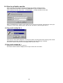
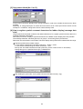
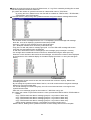
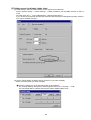
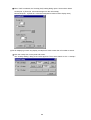
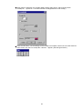
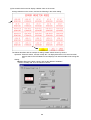
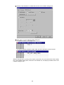
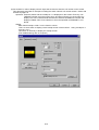
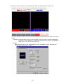
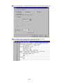
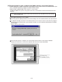
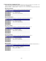
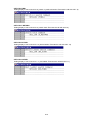
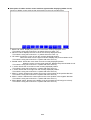
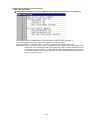
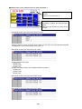
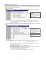
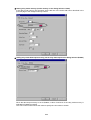
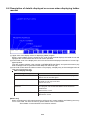
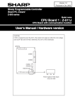
Version 1.1
Produced in May 2002
LCD Control Terminal
ZM-42/43/52/72/82
User's Manual (Ladder Monitor Version)
Thank you for purchasing our LCD control terminal ZM-42/43/52/72/82 (with a
ladder monitor function).
This manual describes how to set up the ladder monitor function of the ZM-42/43/
52/72/82 in order to use it effectively.
The other functions of the ZM-42/43/52/72/82 and screen editor software are
described in the following manuals. Please read them together with this manual.
- LCD control terminal ZM-42/43/52/72/82 (User's manual)
- ZM-71SE screen editor software for the LCD control terminal (Instruction manual)
Notice
- Although this manual was produced with the utmost care, if you find any problems
or have any advice, please contact the shop where you purchased it or write
directly to us.
- Copying all or any part of this manual by any means, without prior written
approval, is prohibited.
- Any portion of this manual may be changed without notice for improvement.
Table of Contents
Before use
Chapter 1: Outline ...................................................................................................... 1-1
Chapter 2: Precautions for use ................................................................................. 2-1
Chapter 3: System Configuration ............................................................................. 3-1
Chapter 4: Connecting to a PC .......................................................................... 4-1 to 2
[1] Compatible PCs ........................................................................................................................ 4-1
[2] Communication settings ............................................................................................................ 4-1
[3] Wiring method ........................................................................................................................... 4-1
Chapter 5: Ladder Monitor Specifications ............................................................... 5-1
Chapter 6: Ladder Monitor Display ................................................................. 6-1 to 26
6-1 Outline of ladder monitor display .................................................................................................. 6-1
6-2 Instruction to display ladder monitors ........................................................................................... 6-1
6-3 Ladder monitor display style ......................................................................................................... 6-1
6-4 How to set ladder monitor ............................................................................................................. 6-2
[1] Copy multi overlap No. 0 ........................................................................................................... 6-2
[2] Copy multi overlap No. 1 ........................................................................................................... 6-2
[3] Copy macro block (No. 0 to 13) ................................................................................................. 6-3
[4] How to register symbol comment characters for ladder display (message data area) .............. 6-3
[5] Setting screen for display ladder chart ...................................................................................... 6-5
[6] System update in order to function the ladder monitor screen data. ....................................... 6-13
6-5 Description of ladder monitor screen data .................................................................................. 6-15
6-5-1 Display area for ladder chart display ..................................................................................... 6-15
6-5-2 Macro for display ladder chart ............................................................................................... 6-15
[1] List of macro command to display ladder chart ....................................................................... 6-15
[2] How to set macro for ladder circuit display .............................................................................. 6-16
(1) Switch lamp memory search instruction ............................................................................ 6-16
(2) Contact point touch search instruction ............................................................................... 6-16
(3) Scroll instruction and search instruction ............................................................................ 6-18
(4) Numeric key memory search instruction ............................................................................ 6-21
(5) Any coil No. search instruction ........................................................................................... 6-23
(6) Relay mode link search instruction .................................................................................... 6-24
6-6 Description of details displayed on screen when displaying ladder monitor ............................... 6-26
Before use
[1] Differences from the ZM-70T's ladder monitor function
Can use a 32-pixel per character font (smooth 4x character font).
However, there is a limitation on the amount of data that can be shown on the screen at one time.
Can use custom 16-pixel characters created by the user.
The ZM-70T uses a custom 16-pixel character file supplied by SHARP to display ladder chart symbols. The ZM-42/43/52/72/82 series can use this custom 16-pixel character file for characters created by the user.
The macro instructions used to display ladder charts are exclusive commands for the ZM-42/43/52/
72/82.
The ZM-70T writes a macro to system memory using division No. 255 of the message mode. However, the ZM-42/43/52/72/82 uses the exclusive commands, and is easier to set up than before.
[2] Other precautions
When using the ladder monitor function, make sure to include an F-40 (END) instruction at the end
of each ladder program.
If an F-40 instruction is not used, the program may not function properly when you try to search for
coils or similar features located at the end of a ladder program.
The ladder monitor function is proprietary SHARP function. It cannot be used with PCs made by
other manufacturers.
In order to use the ladder monitor function, ZM-71SE screen editor software (V1.3.0.0 or later) for
Windows OS and JW-100SP ladder software (V3.02 or later) are required.
When using the ZM-42/43 series, the maximum screen size for these monitors is 320 x 240 pixels.
They cannot display a ladder chart for one complete network on a single screen. In this case, use a
contact point touch function or the scroll function to display the rest of the network.
With the ladder monitor function, a ladder monitor system program will occupy the user screen data
area in the monitor, so the screen data capacity of the user area is decreased by 128K bytes.
When the JW50H/70H/100H series is connected to the monitor, the expansion relay area (address
20000 to 57777) cannot be used for the ladder monitor function. When a JW30H is used, use of area
above address 20000 may require a lot of time to search.
When connecting the ZM series control terminal to a PG port on the control module, if you want to
turn a relay ON or OFF using a switch, the switch cannot be used if the set value change switch
(special relay number 07365) is OFF.
When the monitor is connected to a PC port on a control module, the following error may occur. In
this case, turn OFF the memory protect switch on the control module.
- Error detail: The LCD control terminal will display "Communication error - Receive code 27."
Chapter 1: Outline
The ZM-42/43/52/72/82 series LCD control terminal can display a ladder circuit for a PC (programmable controller) used for facility maintenance.
The LCD control terminal does not contain the entire ladder program in itself, just like the ladder software (JW50SP and others). It searches for the ladder program on a network that has the specified coil number, and
displays the reconstructed ladder chart.
The LCD control terminal only monitors the circuit and it cannot write or modify (edit or delete) the circuit. The
LCD control terminal only can be used with a SHARP PC (JW50H/70H/100H, JW30H, and JW20H series). This
function is enabled when the terminal is connected to a PG port on a control module or a PG port on a JW20CM/JW-20RS/JW-20MN/JW-22CM/JW-21MN. The link system supports PG port communication protocols.
Features
(1) The LCD control terminal searches for a coil with the same lamp memory address as the switch that is
displayed on the screen. It displays the ladder chart for the network that has this coil.
(2) Specify any coil number by using the numeric keys on the screen. The LCD control terminal will display
the ladder chart for a single network that has this coil on an overlapping screen.
(3) By touching a contact point on the displayed ladder chart, the cursor will move there and display a
symbol comment on the lower line of the ladder chart, if one was registered.
After the cursor moves to the contact point you touched, touching the contact point again will cause the
LCD control terminal to search for a coil for this contact point. When found, it will display the ladder chart
for the network with that coil.
(4) By touching a contact point, the screen will return to the most recent ladder screen prior to the current
ladder screen. (You can review up to previous 8 screens)
(5) The LCD control terminal can display the previous and next circuits for the ladder chart being displayed.
(One network each)
(6) The LCD control terminal can search for the previous and next contact points.
(7) A large circuit that cannot be displayed on a single screen can be scrolled.
(In particular, the ZM-42/43 series LCD control terminals have a smaller display area (320 x 240 pixels).
The range that can be displayed at one time is limited.
(8) Since simple operation procedures are used to display a ladder circuit on a running PC, it is easy to
determine a facility's condition and to find out why a facility stopped.
Model names in the ZM-42/43/52/72/82 series
Series
Model name
ZM-42
ZM-42D, ZM-42L
ZM-43
ZM-43T, ZM-43D, ZM-43L
ZM-52
ZM-52D, ZM-52HD
ZM-72
ZM-72T, ZM-72TC, ZM-72TV, ZM-72TVC, ZM-72TS,
ZM-72TSC, ZM-72TSV, ZM-72TSVC, ZM-72D, ZM-72DC
ZM-82
ZM-82T, ZM-82TC, ZM-82TV, ZM-82TVC, ZM-82DC
1-1
Chapter 2: Precautions for use
(1) Installation location and environment
Do not install the LCD control terminal in any of the following locations.
- Where flammable gas, solvents, or coolant liquid are present.
- In locations with salt or metal dust in the air.
- In locations exposed to direct sunlight.
(2) Installation precautions
Carefully consider operability, maintenance requirements, and environmental hazards when installing
an LCD control terminal.
In order to use the terminal within the specified temperature range, do the following.
- Provide enough space for ventilation.
- Do not install the terminal above large heat generating equipment (heaters, transformers, or large
capacity resistors).
- Do not install the terminal inside a panel, which has high-voltage equipment.
- Separate the terminal by 200 mm or more from a high-voltage lines and power lines.
(3) Handling precautions
- Construct an emergency stop circuit using an external relay. Do not use the LCD control terminal for
emergency switches. A malfunction may occur.
- Do not hit, bang or drop the terminal. It may malfunction.
- The surface of the display is easily scratched. Do not operate it using a sharp or pointed object (such as
ballpoint pen) or allow it to be scratched. It may malfunction.
- Tighten the mounting brackets and terminal screws on the terminal using the following torques.
Screw positions
Series name
Control terminal housing
mounting screws
Screw size
Terminal screws
Tightening
Tightening
Screw size
torque (N-m)
torque (N-m)
ZM-42/43/52
M3
0.29 to 0.49
ZM-72/82
M4
0.49 to 0.69
M3.5
0.49
- Lock the connectors on each cable securely. Check that all cables are locked before supplying power.
- In dry locations, large static electricity charges may build up. Before touching the LCD control terminal,
make sure to touch a grounded metal object to discharge any static electricity on your body.
- When cleaning, use a soft, dry cloth. Do not use any volatile liquids, such as alcohol or paint thinner, or
wet cloths. Deformation or color changes may occur.
(4) Wiring
1. Wiring power lines
- Use the terminal within the allowable power voltage fluctuation range.
- Use low noise power supply for lines and ground.
- Separate much 100 VAC and 24 VDC line from high-voltage and large current cables.
2. Provide a ground exclusive for the terminal.
Common use of the ground with other equipment or connect the ground to a building beam may affect
the LCD control terminal.
3. Do not lay communication cables together with high power circuit.
Communication cable
Communication cable
Power lines, control lines
Power lines, control lines
Cable tie
Wiring duct
- Do not run power lines and communications circuits in the same duct. Do not bundle different types of
cables with cable ties. The terminal's noise immunity may deteriorate.
2-1
Chapter 3: System Configuration
Communication module
PG port on a
SHARP PC
(Connector for a
support tool)
(When operating) *1
Connection cable
(ZM-**)
PC model name
JW50/70/100
JW50H/70H/100H
JW20/20H
JW30H
Communication
module name
Control module name
PC model name
JW50/70/100
JW-50CU/70CU/100CU
JW50H/70H/100H JW-50CUH/70CUH/100CUH
ZW-20CM
JW-20CM
JW-20RS
JW-20MN
JW-22CM
JW-21MN
JW30H
JW-32CUH/H1
JW-33CUH/H1/H2/H3
JW20/20H
JW-21CU/22CU
Personal computer
(When sending
an image)
ZM-71SE screen editor software
for ZM series display terminals
*2
Cable
ZM-80PC
Windows 95/98/NT4.0 version
V1.3.0.0 or later
(Hard copy)
Printer
*3
Connection cable
ZM-80PC
NEC: PC-PR201 series
EPSON: ESC/P24-J84, ESC/P super function
HP (Hewlett Packard): PLC Level 3
*1: Prepare this connection cable separately. A D-sub 25P connector (male) is used for
connecting to the display terminal and is supplied as an accessory.
*2: The ZM-80C cable is sold separately.
*3: The ZM-80PC connection cable is sold separately.
Connection
- When installing a communication module in the PC, we recommend connecting a programming tool to the
control module and then you can connect the LCD control terminal (ZM series) to this communication
module.
- When using a JW-20CM, more than one LCD control terminal (ZM series) can be connected to the PG
ports of a single JW-20CM (multi-link connection).
See page 4-2.
ZM-71SE
The following programs are supplied to allow use of the ladder monitor function. These programs are stored
in the "C: ¥ Program Files ¥ Zm71se ¥ Data ¥ Ladder ¥ " folder when the ZM-71SE software is installed for
the first time.
(Instructions for use
See page 6-2.)
- Basic screen data
ZM-82/72TS series: LADDER82.Z71
ZM-72/52 series: LADDER72.Z71 ← Except the TS series for the ZM-72
ZM-42/43 series: LADDER42.Z71
- Communication I/F driver: SHARPPG.TPB version V1.200 or later
3-1
Chapter 4: Connecting to a PC
[1] Compatible PCs
Model setting in the
ZM-71SE
Sharp: PG port
TPB version
V1.200 or later
PC
Module
JW50, JW70, JW100
JW50H, JW70H, JW100H
Control module
ZW-20CM, JW-20CM
JW-20MN
Satellite net module
ME-NET module
JW20H, JW30H
Control module
JW-22CM
JW-21MN
Satellite net module
ME-NET module
- Only version 5.8 or later of the JW-20CM can be used for a multi-link connection. Use MODE "4".
- Use version V1.200 or later for the TPB file in the ZM-71SE.
[2] Communication settings
Item
Setting details
Transfer speed
19200 bps
Data length
8 bits
Parity
Odd
Stop bit
2 bits
Error correction
Checksum
RS-422
4
- When using a multi-link, use
the 2-line system, MODE "4"
Station number
Always "01"
- There is no need to make settings on the PC.
However, if the display terminal cannot
complete a connection to a PC, check the
settings on the left using the ZM-71SE software.
[3] Wiring method
This section describes the cable connection between the LCD control terminal and a PC (control
module, communication module).
Connect a cable to the CN1 connector (TB1 when ZM-52HD is used) on the back of the LCD control
terminal. Connect the other end of the cable to the PG port (connector for a support tool) on a PC.
- When installing a communication module (JW-20CM or the like) in a PC, the PG port on the PC is used
to connect a programmer or ladder software. Therefore, connecting the LCD control terminal to a PG
port on the communication module can be convenient for debugging.
(1) When making an RS-422 connection (a 1:1 connection)
Connection to the PG port (support tool connector) on a JW-50CU/70CU/100CU, JW-50CUH/
70CUH/100CUH, JW-20CM, JW-20RS, or JW-20MN.
PG port on a JW series PC
ZM-** (CN1/TB1)
Signal name
No
Signal name
No
+SD
12
+RXD
2
-SD
13
-RXD
15
+RD
24
+TXD
3
-RD
25
-TXD
16
FG
1
FG
1
4-1
Connection to the PG port (support tool connection connector) on a JW-32CUH/H1, JW-33CUH/
H1/H2/H3, JW-21CU/22CU, JW-22CM, or JW-21MN.
ZM-** (CN1/TB1)
PG port on a JW series PC
Signal name
No
Signal name
No
+SD
12
+RXD
9
-SD
13
-RXD
10
+RD
24
+TXD
3
-RD
25
-TXD
11
FG
1
FG
1
(2) RS-422 (n:1 multi-link connection)
The multi-link connection is only supported on a version 5.8 or later of the JW-20CM. (MODE switch [4])
ZM-**
(CN1/TB1)
ZM-**
(CN1/TB1)
ZM-**
(CN1/TB1)
Signal
name
Signal
name
Signal
name
Signal
name
No
+SD
+SD
+SD
+RXD
2
-SD
-SD
-SD
-RXD
15
+RD
+RD
+RD
+TXD
3
-RD
-RD
-RD
-TXD
16
FG
FG
FG
FG
1
JW-20CM
- Set the terminating resistor switch on all intermediate LCD control terminals to OFF. Set the switch on
the LCD control terminals on each end to ON.
- Common all +SD terminals, all +RD terminals, all -SD terminals, and all -RD terminals on the LCD
control terminals and the PC.
- In order to communicate with more than one display terminal, set the communication response speed
to lowest level.
- Be careful when connecting applications that require rapid response by turning on a switch.
4-2
Chapter 5: Ladder Monitor Specifications
Call a supplied macro instruction by turning ON a switch.
- Touch a switch on the screen.
Display method
Start up method
- Assign a coil number directly using the numeric keys
- Select a message on an error message screen and touch
the execution switch
Display circuit
One network [14 contact points + 1 coil] x 12 lines (ZM-82/72TS series) *1
One network [11 contact points + 1 coil] x 9 lines (ZM-72/52 series) *1, *4
One network [5 contact points + 1 coil] x 6 lines (ZM-42/43 series) *2
- Possible to change the number of lines by adjusting a size of the overlapped
screen.
- Scrollable vertically and horizontally using the cursor keys.
Searchable
elements
Coils, timers, and counters *3
Screen control
function
Basic screen
data
Previous circuit /
next circuit
Display the previous and next circuits for the currently
displayed circuit
Search + / search -
Search for contact points in + and - directions from the
cursor position.
Return search
Return to the previous circuit searched a coil.
Touch contact
point
Move the cursor to the contact point that was touched (when
the cursor is not on a contact point).
After searching for a coil for the contact point that was
touched, displays the circuit (when the cursor is on a contact
point).
Scroll
Scroll in a specified direction: up/down/left/right.
ZM-82/72TS series: LADDER82.Z71
ZM-72/52 series: LADDER72.Z71 *4
ZM-42/43 series: LADDER42.Z71
=> Copy required data from the basic screen data for use.
*1: Cannot display more than two networks at the same time.
*2: When the ZM-42/43 series is used, the screen display size is 320 x 240 pixels and a complete ladder
circuit cannot be displayed on one screen.
These cannot display more than two networks at the same time.
*3: F-32 (SET: coil), DTMR, UTMR, DCNT, and UCNT cannot be used for start up conditions for a search
operation.
*4: Not including the TS series of the ZM-72.
Note: When any JW50H/70H/100H is connected to the LCD control terminal, the expansion relay area
(address 20000 to 57777) cannot be used for the ladder monitor function. When a JW30H is used,
use of the area above address 20000 may take a long time to search.
5-1
Chapter 6: Ladder Monitor Display
6-1 Outline of ladder monitor display
- On a normal display screen, put on an overlap screen. The LCD control terminal displays a ladder
monitor on the display area of this overlapped screen.
- By entering a coil number using the numeric keys on the screen, a ladder monitor can be displayed on
the overlapped screen. (Inputting TMR/CNT number is also available.)
Touch a lamp on the error status screen.
Display a ladder chart on the overlap screen
6-2 Instruction to display ladder monitors
A ladder monitor screen can be displayed by the following methods.
Arrange a switch (setting a lamp memory) on the screen. By touching this switch, the LCD control
terminal searches a ladder circuit of one network having the coil number of this lamp memory, and
displays a ladder monitor on the overlap screen.
Enter any coil number (or TMR/CNT number) using the numeric key input screen, the LCD control
terminal searches a ladder circuit of one network having this coil number, and displays a ladder monitor on the overlapped screen.
An application example
- Linking with relay mode (message display), the LCD control terminal searches a ladder circuit of
one network having this coil number, and displays the ladder monitor on the overlapped screen.
- Display a ladder monitor by assigning any memory of a switch.
Once a ladder chart is displayed, touch (1st time) a contact point on the ladder chart. The cursor moves to
the touched contact point and displays one line of symbol/comment below the ladder chart if a comment
is registered.
Again touch the cursor (2nd time); the LCD control terminal searches a coil for this contact point.
If the coil exists, the LCD control terminal displays a ladder chart having this coil.
If the coil does not exist, the LCD control terminal displays a "NETWORK NOT FOUND" message.
6-3 Ladder monitor display style
When displaying a ladder monitor, the control terminal uses its display style and call overlap.
"Call overlap" is to set one overlap screen. By setting this, the same overlap screen can be displayed on
any screen.
On the call overlap screen used, a contact point switch is arranged (translucent) for executing coil search
by pressing the contact point on the ladder chart.
6-1
6-4 How to set ladder monitor
Start up the ZM-71SE software and set according to the setting procedures below.
Copy screen data of the basic screen data [LADDER82.Z71] to set a ladder monitor.
On the software tool bar, select "File" → "File Manage" → "Screen data file" in that order.
Select "LADDER82.Z71" (basic screen data) in the Copy Source column, and enter file name (Ex.
"TEST.Z71") in the Copy Target column and click the "OK" button. (See the figure above.)
[1] Copy multi overlap No. 0
Click the icon of the multi overlap No. 0 of the source data, and drag (draw while pressing down the left
mouse button) to the No. 0 position of a copy destination. Now the copying is complete.
This will be a button switch used to the display ladder monitor screen.
[2] Copy multi overlap No. 1
Same as the procedures above, copy No. 1.
This will be a button switch to display numeric keys to enter the coil number.
6-2
[3] Copy macro block (No. 0 to 13)
If some macro blocks are already used, change numbers in order not to double the same macro block
numbers.
Especially, to change description of switch ON macro that is set to contact point search switch of multi
overlap No. 0 is difficult, change macro block number already used.
[4] How to register symbol comment characters for ladder display (message data
area)
Using symbol/comment data created on the ladder software for PC, register symbol/comment data in the
message data area of ZM series.
With these procedures, display of symbol/commend on the ladder monitor display becomes possible.
The message data area: 256 lines (pieces) x 24 groups = 6144 lines (pieces) at maximum.
Determine use ratio between normal alarm character display and symbol/comment data within this range.
Prepare symbol/comment data created.
In case of data created using JW-50SP: Extension; *.SYE or *.SYM
In case of data created using JW-100SP: Extension; *.SYC
Start up the JW-100SP software and load symbol file. (V3.02 or later version of JW-100SP)
Change file type to a specified format. [Ex.] LADDER.SYC
After loading the symbol file, save symbol/comment with ZM70 format (*.mg).
6-3
When the symbol/comment is saved in ZM70 format, a "*.mg" file is created by dividing files so each
has 256 symbols/comments at maximum.
[Ex.] When the number of symbols/comments is 1000 and file name is "TEST.SYC."
By saving this file in ZM70 format, four files will be created as "TEST01.MG," "TEST02.MG,"
"TEST03.MG," and "TEST04.MG."
Load the text file (*.MG) having 256 symbols/comments using the software message edit function.
- On the basic screen, message block No. 0 to 11 for displaying normal message and message
block No. 12 to 23 for displaying symbol/comment are provided.
- Open the "*.MG" file using software that can handle text files.
(Ex.: "Notepad" software as an accessory of Windows OS)
- Copy line 0 to 255 and paste to message group No. 12 on the ZM-71SE message edit screen
using the copy and paste function of Windows.
In this case, check that number of messages per one message group is 256 (No. 0 to 255).
- If a carriage return is added at the end of each line, delete these using the back space key.
When the cursor reaches to the last line of the messages, check that the number of lines displayed
at the lowest row of the window display on the status display bar shows 1 to 255. (See the figure
below.)
If this indication shows more than 256, the data exceeds the maximum capacity. Delete lines
exceeding 256 lines.
- By converting the symbol/comment data of the PC, the LCD control terminal recognizes message
data as PC symbol/comment data.
If a normal message is entered using keys, the LCD control terminal does not recognize it as
symbol/comment data.
- After this, move message groups for the number of "*.MG" files one by one.
[Ex.] When the number of symbols/comments is 1000, proceed with TEST01.MG to TEST04.MG as
follows.
Copy "TEST01.MG" text data to message group No. 12 (number of data: 256)
Copy "TEST02.MG" text data to message group No. 13 (number of data: 256)
Copy "TEST03.MG" text data to message group No. 14 (number of data: 256)
Copy "TEST04.MG" text data to message group No. 15 (number of data: 232)
(When setting message group No. 12 and after as symbol/comment area.)
With the above, loading of PC symbols/comments on the message edit screen is complete.
6-4
[5] Setting screen for display ladder chart
(1) Initial setting in order to use the ladder monitor (Select from edit items).
Select "System setting" → "Other settings" → Make possible to use the ladder monitor on the P3
menu.
Click the check box " □ Use Ladder Monitor." (See the figure below.)
If you cannot put check mark because the characters are changed to meaningless symbols, reset the
PLC type to "SHARP: PG port."
(2) Set for overlap display of ladder chart on a screen to you want to display.
Move to an edit screen you want to display.
Click the overlap icon on the part edit screen of the software.
The "Overlap Setting" dialog shown below appears. Select "No. 0 Overlap" → "Call."
This call overlap will be a button switch that is used to display ladder chart.
6-5
When "Call" is selected, the "Overlap (Call)" setting dialog opens. Set as shown below.
Overlap No.: 0 (Enter No. 0 that was assigned for the call overlap.)
Multi Overlap No.: 0 (Enter No. 0 that was assigned for ladder monitor display area.)
(3) Set for displaying numeric key display overlap that is used to enter the coil number to search.
Click the overlap icon on the parts edit screen.
The "Overlap Setting" dialog shown below appears. Then, select "Multi" for "No. 1 Overlap."
6-6
When "Multi" is selected, the "Overlap (Multi)" setting dialog opens. Set as shown below.
Overlap No.: 1 (Enter No. 1 the same number as assigned for the multi overlap.)
Clock the OK button, now the settings for the overlap are complete. On the bar icon at the lower left
of the screen, two icons of overlap No. 0 and No. 1 appear. (See the figure below.)
6-7
(4) Set a switch that is used to display a ladder chart on the screen.
Arrange switches on the screen, and set the following in the switch dialog.
A
B
The below describes with an example of setting "05000" switch shown by arrow A.
Operation: Press this switch, and the overlap No. 0 is displayed and the LCD control terminal
starts to search the OUT05000 coil and displays one network ladder chart having this
coil.
Setting:
Make effective the lamp memory and set the address "0005000."
Enter "Overlap: ON: 0" to the Function column.
6-8
Click the "Use ON Macro" to enable this function on the "Detail" setting menu.
Enter "CALL 0" in the "ON Macro Edit" dialog box.
For details of "CALL 0," see page 6-16.
Or, with the following "ON Macro Edit" detail, the same operation can be executed.
With the settings above, pressing of this switch causes the LCD control terminal to show overlap
No. 0 of the ladder display area, searches for OUT05000 coil, and displays a ladder chart of one
network having this coil.
6-9
(5) Set a switch in order to display numeric keys that are used to enter the coil number on the screen.
This paragraph describes an example of setting the switch named "coil number search" shown with
arrow B on page 6-8.
Operation: Press this switch and the overlap No. 1 is displayed on the screen. Enter any coil/
TMR/CNT number using the numeric keys, and press "Search" on the numeric key
display. The LCD control terminal searches the entered coil/TMR/CNT number and
displays a ladder chart of one network in which the specified coil/TMR/CNT is contained.
Setting:
Enter "Multi-Overlap: O:1M:1" on the function column.
This is to set a switch to display a multi overlap screen of the multi No. 1 using overlap No. 1
from No. 0 to 2.
This switch is used only to display the overlap screen.
(The detailed settings are not required.)
6-10
(6) Set a switch that is used to search and display a ladder chart linking with the relay mode.
Arrange a switch on the screen and set the following on the switch dialog.
The below describes setting a switch named "ERR LINK" that is encircled by an ellipse on the figure
above.
Operation: Press this switch, and if an error message occurs, the LCD control terminal displays
overlap No. 0 and searches a coil linking with the relay mode memory, and displays a
ladder chart of one network having this coil.
Setting:
Do not select any on the "Output Memory" and "Lamp Memory" items, and select "No
Function" in the Function column.
6-11
Click "Use ON Macro" to make effective this function on the "Detail" setting menu.
For "ON Macro Edit," enter the macro instruction of the figure below.
As for macro instruction details, see page 6-24 and after.
6-12
[6] System update in order to support the ladder monitor screen data function.
In order to display the ladder monitor, the "main program" and "I/F driver" of the LCD control terminal (ZM
series) should be updated to support the ladder monitor function.
Ladder monitor supported ZM-71SE version: V1.3.0.0 or later
- In order to update the system, it may take much time as all the data must be transferred to the main
housing.
Note: While upgrading the system, make sure to never turn OFF the power of the LCD control
terminal (ZM series).
System update procedures are as follows.
Click the [System update] button on the transfer dialog. The LCD control terminal starts data transfer.
If a program already sent to the LCD control terminal is the same or a later version than the program
you are trying to send using the "system update" function, the LCD control terminal displays the following message.
Select "YES" for all the items.
After the data transfer is compete, the LCD control terminal returns to the original condition.
Display the "local main" screen on the monitor and check the version information.
6-13
Ladder monitor supporting version
ZM-71SE
V1.3.0.0 or later
SYSTEM PROG. VER.
V1.240 or later * If you make a mistake about version, the
"ERROR code 152" is occured.
I/F DRV VER
V1.200 (For SHARP JW PGPORT)
Ladder program
VER. 1.200 or later
(* Display by pressing the extension program information switch.)
* If the extension program information switch is not displayed, the system may not be properly updated.
Try updating the system software again.
6-14
6-5 Description of ladder monitor screen data
6-5-1 Display area for ladder chart display
Specify [Display Area] inside the multi overlap with the following details.
The basic screen "LADDER82.Z71" corresponds to multi overlap No. 0.
Item
Set detail
Division No.
0
Foreground
White (recommending)
Background
Blue (recommending)
Tile
None (recommending)
□ Ladder Monitor display
Put a check mark in the check box.
6-5-2 Macro for display ladder chart
[1] List of macro commands to display ladder chart
Special commands with dedicated use for display ladder charts are listed below.
Use for macro block No. 0 to 13 of the basic screen "LADDER82.Z71" and ON macro in the switch.
SETーLDR
command name
Details
UPーSCROLL
Scroll up: Moves the cursor up
If the cursor is at the upper end of a circuit, moves to the previous
circuit.
DWーSCROLL
Scroll down: Moves the cursor down
If the cursor is at the upper end of a circuit, moves to the
previous circuit.
LーSCROLL
Scroll left: Moves the cursor left.
RーSCROLL
Scroll right: Moves the cursor right.
FIND-
Search (-): Searches for contact points in negative direction.
FIND+
Search (+): Searches for contact points in positive direction.
FーRETURN
Search return: Returns to the ladder circuit searched before (up to 8 times.)
BFーFIND
Search previous circuit: Displays the previous circuit of the currently
displayed circuit.
NXーFIND
Search next circuit: Displays the next circuit of the currently displayed circuit.
TーFIND
Detect contact point touched: Recognizes which contact point is pressed on
the circuit.
MEMーFIND
Search switch lamp memory: Searches with the lamp memory.
COILーFIND
Search any coil no.: Detects any coil.
6-15
[2] How to set macro for ladder circuit display
There are four types of parameters to specify searching memory No. for displaying ladder circuit.
In addition, two examples can be set.
- Parameter type 0 — Switch lamp memory search instruction
(1)
- Parameter type 1 — Contact point touch search instruction
(2)
- Parameter type 2 — Scroll, search input
(3)
- Parameter type 3 — Numeric key memory search instruction
(4)
- Application example 1 — Any coil No. search instruction using a switch
(5)
- Application example 2 — Relay mode linked search instruction
(6)
(1) Switch lamp memory search instruction
This is a mode to start searching triggered by lamp memory address (coil number) that was created using
software, and then display the ladder chart after it is created.
- SET-LDR: MEM-FIND
With the basic screen "LADDER82.Z71," use macro block No. 0.
- Search a coil of the memory number set in the lamp memory.
- Select the "Detail" → "ON Macro Edit" and assign "CALL 0."
Setting display of macro block No. 0 (Switch lamp memory search: Execute call by CALL 0)
(2) Contact point touch search instruction
Use for contact point touch control after displayed a ladder chart.
- SET-LDR: T-FIND
With the basic screen "LADDER82.Z71," use macro block No. 1.
Arrange on the multi overlap No. 0 screen of the "LADDER82.Z71."
(Number of translucent switches: 15 (vertical) x 12 (horizontal) = 180 pieces)
Select the "Detail" → "ON Macro Edit" and assign "CALL 1."
Setting display of macro block No.1 (Switch touch search: Execute call by CALL 1)
6-16
Description of multi overlap No. 0 (call overlap) screen
For displaying ladder circuit, switches are arranged on a matrix of 15 (horizontal) x 12 (vertical).
Secure space for 2 grids (left and right of a switch) and arrange a switch occupying 3 (horizontal) x 2
(vertical) so that the switch is arranged with the same pitch as one of the ladder chart contact points.
Note: The screen above is shown with colored switch frames for explanation purpose. In the actual
screen, the switch frames are white and cannot be seen.
On the actual screen, translucent switches will be arranged on the contact points.
Switch function of the contact point touch search instruction
Contact point where the cursor does not highlight: The cursor moves to the touched contact point.
Check command display.
The LCD control terminal searches a coil of the
Contact point where the cursor highlights:
touched contact points and displays the ladder
circuit.
6-17
(3) Scroll instruction and search instruction
On the basic screen "LADDER82.Z71," these instructions use macro blocks Nos. 2 to 5, and Nos. 7 to 11.
These are arranged on the multi overlap No. 0 screen of the "LADDER82.Z71."
Select the "Detail" → "ON Macro Edit" → "Call 2 to 5, 7 to 11," in that order to assign these instructions.
- SET-LDR: UP-SCROLL
Setting display of macro block No. 2 (scroll up: Executes the call with CALL 2)
- SET-LDR: DW-SCROLL
Setting display of macro block No. 3 (scroll down: Executes the call with CALL 3)
- SET-LDR: L-SCROLL
Setting display of macro block No. 4 (scroll left: Executes the call with CALL 4)
- SET-LDR: R-SCROLL
Setting display of macro block No. 5 (scroll right: Executes the call with CALL 5)
- SET-LDR: FINDSetting display of macro block No. 7 (search in the negative direction: Executes the call with CALL 7)
6-18
- SET-LDR: FIND+
Setting display of macro block No. 8 (search in positive direction: Executes the call with CALL 8)
- SET-LDR: F-RETURN
Setting display of macro block No. 9 (search back: Executes the call with CALL 9)
- SET-LDR: BF-FIND
Setting display of macro block No. 10 (before ladder: Executes the call with CALL 10)
- SET-LDR: NX-FIND
Setting display of macro block No. 11 (next ladder: Executes the call with CALL 11)
6-19
Description of ladder monitor control switches (operate after displaying ladder circuit)
Function of ladder control switches that are arranged on the multi overlap screen.
1. "Before LD" switch: Displays the previous circuit of the currently displayed circuit.
- This switch is using macro block No. 10 (switch ON macro CALL 10).
2. "Next LD" switch: Displays the next circuit of the currently displayed circuit.
- This switch is using macro block No. 11 (switch ON macro CALL 11).
3. "UP" switch: Scrolls the cursor up from the currently displayed position.
When the cursor is on the upper most line, displays the previous ladder circuit.
- This switch is using macro block No. 2 (switch ON macro CALL 2).
4. "DOWN" switch: Scrolls the cursor down from the currently displayed position.
When the cursor is on the upper most line, displays the previous ladder circuit.
- This switch is using macro block No. 3 (switch ON macro CALL 3).
5. "<" switch: Scrolls the cursor left from the currently displayed position.
- This switch is using macro block No. 4 (switch ON macro CALL 4).
6. ">" switch: Scrolls the cursor right from the currently displayed position.
- This switch is using macro block No. 5 (switch ON macro CALL 5).
7. "SRCH +" switch: Searches the contact point on the cursor position in the positive direction.
- This switch is using macro block No. 8 (switch ON macro CALL 8).
8. "SRCH -" switch: Searches the contact point on the cursor position in the negative direction.
- This switch is using macro block No. 7 (switch ON macro CALL 7).
9. "SRCH BACK" switch: Returns to the ladder circuit of the searched coil last (up to 8 times).
- This switch is using macro block No. 9 (switch ON macro CALL 9).
6-20
(4) Numeric key memory search instruction
- SET-LDR: COIL-FIND
Setting display of macro block No. 6 (Numeric key input search: Executes call by CALL 6)
On the basic screen "LADDER82.Z71," this instruction is used for macro block No. 6.
This is used for ON macro edit of the multi overlap No. 1 "Search" switch.
Select the "Detail" → "ON Macro Edit" → "CALL 6," in that order to assign this function.
Description: In the lines 2 to 4 of the above edit dialog box, it is programmed to turn ON the multi
overlap No. 0 (for displaying ladder circuit) when the "Search" switch (described in the
next page) is pressed. Lines 7 to 9 are programmed to determine the entered memory
number ($u1000) and memory type ($u1001: One from Coil/TMR/CNT) and enters into
the circuit search process.
6-21
Numeric key screen setting screen of multi overlap No. 1
Displays data entered using the numeric keys
$u1000
Used for macro block No. 6
A switch to select from coil/TMR/CNT.
By selecting a switch, the respective lamp
lights.
Determine the selection by detail of the
$u1001.
- Description of ON macro edit of the "Search" screen
Press the "Search" screen using the "write" switch function; the LCD control terminal writes the
coil/TMR/CNT number and executes macro CALL 6.
- Description of ON macro edit of the "Coil" switch
$u1001 shows memory type
1(HEX): Coil
7(HEX): TMR
8(HEX): CNT
$u1002 is for lamp memory. (The selected switch lamp lights.)
1(HEX): Coil
4(HEX): TMR
8(HEX): CNT
- Description of ON macro edit of the "TMR" switch
- Description of ON macro edit of the "CNT" switch
6-22
Display open macro setting of multi overlap No. 1
When the multi overlap is opened, the LCD control terminal turns ON the numeric key memory $u0700
write enable bit (0th line), and makes possible numeric key input.
The LCD control terminal first lights the "Coil" lamp and waits for coil number input. (1st to 2nd lines)
(5) Any coil No. search instruction
If you want to search for any memory coil, but not search for a coil of the switch lamp memory, execute with
the following procedures.
- SET-LDR: COIL-FIND
Display setting of macro block No. 12 (Search option coil: Execute with CALL 12)
Link to option memory
$u0200.
When searching for any coil, register the following formula for the ON macro of the starting up
switch
Assign option memory.
Ex.: If you want to arrange detects OUT 04000 by pressing a certain switch, enter 04000(W)(OCT)
to $u0200 with octal constant.
With this, set the lamp memory of the switch to coil 6000 and when 6000 turns ON (error condition), the LCD control terminal displays ladder circuit of coil 04000 (a coil to check).
6-23
(6) Relay mode link search instruction
The software can link ladder monitor display by directly searching a coil which is turning ON the error
message specified by the cursor, when an error message or the like is displayed with relay mode. For
example, on a message of "Limit switch error," you can display the ladder circuit of the coil at which an
error occurred by one touch switch operation.
- SET-LDR: COIL-FIND
Display setting of macro block No. 13 (Linking to relay mode: Execute call with CALL 13)
$u0802
Check which memory is
shown by the cursor counting from the top of the relay
mode memory.
Description: Memory value selected by the cursor on the screen is entered into $u0401. The LCD
control terminal searches the coil of the memory number selected by the cursor and
displays. (Line 5 to 7)
To enable entry of relay mode link coil memory, register the following format to the switch ON
macro
Relay mode information
Links with output memory.
If no message is displayed,
the screen does not display
the ladder monitor.
Links with relay mode
memory.
Description: When no message is displayed, the LCD control terminal does not start the ladder
monitor.
Jump to 12th line (2nd line)
When there is a message displayed, the LCD control terminal turns ON the overlap
screen. (4th to 6th lines)
Set the relay mode top memory 10000 to $u0400. (9th line)
When the LCD control terminal changes relay mode memory, change the 9th $u0400 to
the changed relay number.
Ex.: When the relay mode memory is changed to 12000,
Set the 9th line to $u00400 = 12000 (W).
The LCD control terminal starts relay mode linked search with CALL13.
6-24
Setting relay mode memory (set the memory on the dialog below to 10000)
If the relay mode memory was changed, set the 9th line of the switch ON macro described in the
previous page to the changed memory number.
Setting relay mode data output memory (set the relay data output on the dialog below to $u0800)
When the data output memory is set to $u0800, a value of which bit of the relay mode memory is
selected for $u0802 is entered.
The LCD control monitor shows this value to specify the coil number to search.
6-25
6-6 Description of details displayed on screen when displaying ladder
monitor
(1) Upper zone of the display area is for displaying ladder program.
When a correct ladder circuit is searched, the LCD control terminal displays the ladder circuit and
highlights the coil and enters into the circuit monitor operation.
(2) At the lower zone of the display area, the LCD control terminal displays information of cursor highlighted position.
They are program address, relay number (coil/TMR/CNT/FUNCTION), and symbol/comment (only
when message is set for symbol/comment data) from the left to right.
(3) If the LCD control terminal could not search a coil properly, it displays any of the messages below at
lower end of the display area.
Table of display message
Message description
NETWORK NOT FOUND
INSTRUCTION READ ERROR
LADDER NETWORK CANNOT
DISPLAY
NETWORK DATA SIZE OVER
Description
- Specified coil number could not be found in the program.
- Check the coil number again.
- Failed to read an instruction.
- A ladder circuit may have fault.
- Check the circuit.
- Ladder circuit cannot be displayed.
- The program has a fault that ladder circuit cannot be
established.
- Recheck the circuit.
- Capacity of one network is exceeded.
- Review the circuit.
[Before use]
When connecting the LCD control terminal to a PG port of a control module, the following error may
occur. In this case, turn OFF the memory protect switch of the control module.
- Error details: "Communication error: Receive code 27"
6-26