1
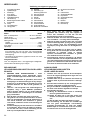
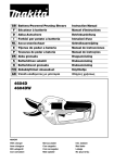
GB Battery-Powered Pruning Shears
Instruction Manual
F
Sécateur à batterie
Manuel d’instructions
D
Akku-Astschere
Betriebsanleitung
I
Forbici per potate a batteria
Istruzioni d’uso
NL Accu-snoeischaar
Gebruiksaanwijzing
E
Tijeras de podar a batería
Manual de instrucciones
P
Tesouras de podar a bateria
Manual de instruções
DK Akku grensaks
Brugsanvisning
S
Batteridriven sekatör
Bruksanvisning
N
Batteridrevet grensaks
Bruksanvisning
SF Akkukäyttöiset oksasakset
Käyttöohje
GR Ψαλίδι κλαδέµατος µε µπαταρία
Οδηγίες χρήσεως
4604D
4604DW
4604DW
With charger
Avec chargeur
Mit Ladegerät
Con caricatore
Met acculader
Con cargador
Com carregador
Med oplader
Inkl. laddare
Med lader
Lataaja
Με φρτιστής
5
6
3
2
1
7
4
1
2
8
8
9
9
10
10
11
4
3
4
13
16
12
14
12
14
15
5
6
12
18
17
7
2
19
8
20
22
19
21
9
10
23
17
24
11
12
26
25
27
13
14
28
27
15
16
3
29
23
23
29
30
17
18
31
26
24
19
20
23
32
21
33
22
33
24
23
4
24
25
5
ENGLISH
Explanation of general view
1
2
3
4
5
6
7
8
9
10
11
Charger DC4600
Charging light
Start button
Battery 4600
Charging plug
Charging connector
Restart button
Controller C4600
Switch
Buckle
Pilot lamp
12
13
14
15
16
17
18
19
20
21
22
Waist belt
Pocket lid
Controller connector
Waist belt pocket
Suspenders
Holster
Arm band
Connection cord
Female plug
Switch trigger
Lock-off lever
SPECIFICATIONS
Model
4604D
Max. cutting capacity ......................... 30 mm in diameter
Overall length ..................................................... 286 mm
Rated voltage ................................................... D.C. 24 V
Net weight
Shears ................................................................ 1.0 kg
Controller C4600 ................................................ 0.3 kg
Battery 4600 ....................................................... 2.0 kg
Charging time .............................................. Approx. 1 hr.
23
24
25
26
27
28
29
30
31
32
33
Upper shear blade
Lower shear blade
Branch
Hex wrench
Blade cover
Socket wrench
Blade holder
Magnet
Brush
Machine oil
Diamond file
9.
Do not operate charger if it has received a sharp
blow, been dropped, or otherwise damaged in
any way; take it to a qualified serviceman.
10. Do not disassemble charger or battery; take it to
a qualified serviceman when service or repair is
required. Incorrect reassembly may result in a
risk of electric shock or fire.
11. To reduce risk of electric shock, unplug charger
from outlet before attempting any maintenance
or cleaning. Turning off controls will not reduce
this risk.
• Due to our continuing program of research and development, the specifications herein are subject to change
without notice.
• Note: Specifications may differ from country to country.
ADDITIONAL SAFETY RULES FOR CHARGER
& BATTERY
Safety hints
For your own safety, please refer to the enclosed safety
instructions.
2.
1.
3.
IMPORTANT SAFETY INSTRUCTIONS FOR
CHARGER & BATTERY
4.
1.
5.
2.
3.
4.
5.
6.
7.
8.
6
SAVE THESE INSTRUCTIONS — This manual
contains important safety and operating instructions for battery charger.
Before using battery charger, read all instructions and cautionary markings on (1) battery
charger, (2) battery, and (3) product using battery.
CAUTION — To reduce risk of injury, charge only
MAKITA type rechargeable batteries. Other types
of batteries may burst causing personal injury
and damage.
Do not expose charger to rain or snow.
Use of an attachment not recommended or sold
by the battery charger manufacturer may result
in a risk of fire, electric shock, or injury to persons.
To reduce risk of damage to electric plug and
cord, pull by plug rather than cord when disconnecting charger.
Make sure cord is located so that it will not be
stepped on, tripped over, or otherwise subjected
to damage or stress.
Do not operate charger with damaged cord or
plug — replace them immediately.
6.
7.
8.
Do not charge battery when it or air temperature
is below 10°C (50°F) or above 40°C (104°F).
Do not charge or leave battery in a location
exposed to direct sunlight.
Do not attempt to use a step-up transformer, an
engine generator or DC power receptacle.
Do not allow anything to cover or clog the
charger vents.
Do not short the battery:
(1) Do not touch the terminals with any conductive material.
(2) Avoid storing battery in a container with
other metal objects such as nails, coins, etc.
(3) Do not expose battery to water or rain.
A battery short can cause a large current flow,
overheating, possible burns and even a breakdown.
Always cover the battery terminals with the battery cover when the battery is not used.
Do not incinerate the Battery even if it is severely
damaged or is completely worn out. The battery
can explode in a fire.
Be careful not to drop, shake or strike battery.
Do not charge inside a box or container of any
kind. The battery must be placed in a well ventilated area during charging.
ADDITIONAL SAFETY RULES FOR BATTERYPOWERED PRUNING SHEARS
1.
This machine is for pruning branches. Do not
use it for any job except that for which it is
intended.
2. Don’t use the machine or perform battery charging operations in the rain.
3. Don’t leave the machine in rain or wet locations.
4. Keep bystanders well away from your work area.
5. Be careful not to catch foreign matter between
the blades. If the blades are jammed with foreign
matter, immediately switch off the machine and
disconnect the battery from the machine. Then
remove the foreign matter from the blades.
6. Never hold the branch you are pruning with your
free hand. Keep your free hand away from the
cutting area. Never touch the blades, they are
very sharp and you may cut yourself.
7. Don’t force the machine to make it cut. You could
slip and injure yourself or cut something else
unintentionally.
8. Avoid cutting electrical wires that may be hidden.
9. Always check the blades carefully before operation.
10. Handle the blades with extreme care to prevent
cuts or injury from the blades.
11. Disconnect the battery from the machine after
each use and before attempting to perform
inspection or maintenance.
12. When not in use, always keep the machine in its
holster.
SAVE THESE INSTRUCTIONS.
OPERATING INSTRUCTIONS
Charging (Fig. 1 & 2)
Charge the battery 4600 with the Makita charger
DC4600 before use. Plug the charger into the power
receptacle and connect the charging plug into the charging connector on the battery. Press the start button (red)
on the charger. The charging light will come on and
charging will begin. When the charging light goes out
after about one hour, the charging will be completed. If
the charging light goes out within one minute after pressing the start button, the battery is dead. Replace it with a
new one. After charging, disconnect the charging plug
from the battery and power receptacle.
CAUTION:
• Remove the controller from the battery when charging.
• Do not keep the start button depressed with tape, etc.
The circuit will not function properly and a malfunction
of the charger may result.
• Use only Makita charger DC4600 to charge the battery
4600. The use of any other chargers may cause damage to the battery.
• When you charge a new battery or a battery which has
not been used for a long period, it may not accept a full
charge. This is a normal condition and does not indicate a problem. You can recharge the battery fully after
discharging it completely a couple of times.
Overcurrent relay (Fig. 2)
The overcurrent relay is built into the battery to prevent a
battery short-circuit. When the overcurrent relay actuates, the battery cannot be used. Press the restart button
on the battery to use it again. If the overcurrent relay
actuates frequently, there may be something wrong with
the battery, charger, controller or shears themselves.
Send them to your dealer or a Makita Service Center to
have them inspected and/or repaired.
Installing controller on battery (Fig. 3 & 4)
First, make sure that the controller is switched off. Install
the controller on the battery and fasten it with the buckles.
Connecting connection cord to controller
Connect the male plug of the connection cord to the controller connector and turn the screw clockwise to secure
the male plug in place.
Putting battery into waist belt pocket (Fig. 5 & 6)
After installing the controller on the battery, put the battery with the controller into your waist belt pocket so that
the controller connector will point toward your hand with
which you operate the shears. Then cover the battery
with the pocket lid to keep them from accidentally falling
out of your pocket during operation.
Wearing waist belt (Fig. 6)
Attach a pair of suspenders on the waist belt. Wear the
waist belt and adjust the lengh of suspenders and waist
belt so that the battery will be positioned on your back at
waist height.
Installing holster (Fig. 7)
Install the holster on the waist belt as shown in Fig. 7. It
should be positioned on the side where your hand operates the shears.
Wearing arm band (Fig. 8)
Attach the arm band to your arm. When wearing it, slip
the connection cord through the arm band as shown in
Fig. 8 to keep it out of the way.
Connecting connection cord to shears (Fig. 9)
Connect the female plug of the connection cord to the
shear connector and turn the screw clockwise to secure
the female plug in place.
NOTE:
If you connect or disconnect the connection cord with the
controller switched on, the pilot lamp will blink red and
green alternately. When this occurs, the shears will not
start even if you pull the switch trigger. Switch off the controller and then switch it on again to start the shears.
(Fig. 4)
7
Switch action
Pilot lamp on controller (Fig. 4)
CAUTION:
• Before connecting the battery to the shears, always
check to see that the switch trigger actuates properly
and returns to the “OFF” position when released.
• Do not pull the switch trigger without depressing the
lock-off lever. It can cause switch breakage.
The pilot lamp will start to blink or remain green when the
controller is switched on (the upper (I) side of the switch
is pressed). If the pilot lamp indicates the following conditions, proceed as follows.
1. If the pilot lamp blinks red and green alternately, the
overload protecting mechanism has been actuated
or the connection cord is not firmly connected.
Switch off the controller and do the following:
a) If the motor is locked for more than three
seconds, just switch on the controller.
b) If the connection cord is not connected firmly,
connect the connection cord firmly and then
switch on the controller.
2. If the pilot lamp blinks red, the inside of the controller
is too hot. Switch off the controller and wait for a
while to cool it down. Then switch it on.
3. If the pilot lamp remains red continuously, the battery voltage is too low. Charge the battery.
4. If the pilot lamp is neither green or red:
a) The battery is completely discharged. Charge
the battery.
b) The overcurrent relay has actuated. Press the
restart button.
Switch on the controller by pressing the upper (I) side of
the switch. The pilot lamp will start to blink green. Then
pull the switch trigger and release it once. The upper
shear blade will start to move up as soon as you release
the switch trigger and will stop at the highest (wide open)
position. In case that the upper shear blade has already
opened, it will keep that position with the first trigger
operation. The pilot lamp will remain green continuously.
From the next trigger operation, you can cut branches.
(Fig. 4)
To prevent the switch trigger from being accidentally
pulled, a lock-off lever is provided. To start the shears,
depress the lock-off lever and pull the switch trigger. To
stop the shears, release the switch trigger. (Fig. 10)
When the switch trigger is pulled and held, the upper
shear blade will move down and stop at the closed position. When the switch trigger is released, the upper shear
blade will move up and stop at the highest (wide open)
position. (Fig. 11)
Putting shears in holster (Fig. 12)
Switch off the controller by pressing the lower (O) side of
the switch while keeping the switch trigger pulled. The
upper shear blade will stop at the closed position. Put the
shears in the holster with the upper shear blade at the
closed position.
Pruning operation (Fig. 13)
CAUTION:
• Never operate the shears in an awkward posture. This
may cause a serious injury.
• Never hold the branch you are pruning with your free
hand. Keep your free hand away from the cutting area.
The blades are very sharp and you may cut yourself.
Cut branches one by one as shown in Fig. 13. The maximum thickness of branches which can be cut with these
shears is about 30 mm. Maintain your proper footing and
balance at all times.
After use, switch off the controller and disconnect the
connection cord from the shears and the controller. Store
the shears in dry, high or locked-up place – out of reach
of children.
Overload protecting mechanism
Both the shears and the controller are equipped with an
overload protecting mechanism. If the motor is locked for
more than three seconds, this mechanism will actuate to
stop the shears. Also, the pilot lamp on the controller will
start to blink red and green alternately. To resume operation, switch off the controller by pressing the lower (O)
side of the switch, then switch it on again.
NOTE:
Do not operate the shears in such a way that this mechanism actuates frequently. The motor may be damaged.
8
If the pilot lamp does not start to blink green even after
you perform the above procedures, there is something
wrong with the shears, connection cord, controller or battery. Switch off the controller and disconnect the connection cord from the shears and the controller. Remove the
controller from the battery. Send the shears, connection
cord, controller and battery to your dealer or a Makita
Service Center to have them inspected and/or repaired.
Replacing shear blades
CAUTION:
Always be sure that the controller is switched off and the
connection cord is disconnected from the shears.
The shear blades can be replaced irrespective of the
upper shear blade position.
Use the hex wrench provided to remove the two hex
socket head bolts which secure the blade cover. (Fig. 14)
Remove the blade cover. (Fig. 15)
Use the socket wrench provided to remove the hex lock
nut. The flat washer will come off together with the hex
lock nut. (Fig. 16)
Remove the round head bolt, blade holder and upper
shear blade. (Fig. 17)
Remove the upper shear blade from the blade holder. Be
careful not to allow any foreign matter to attach to the
magnet on the blade holder and do not damage it.
(Fig. 18)
Use the hex wrench provided to remove the two hex
socket head bolts which secure the lower shear blade.
Then remove the lower shear blade. (Fig. 19)
To install the shear blades, follow the removal procedures
in reverse. Do not remove grease around the gear.
MAINTENANCE
ACCESSORIES
CAUTION:
Always be sure that the controller is switched off and the
connection cord is disconected from the shears.
CAUTION:
These accessories or attachments are recommended for
use with your Makita machine specified in this manual.
The use of any other accessories or attachments might
present a risk of injury to persons. The accessories or
attachments should be used only in the proper and
intended manner.
Blade maintenance (Fig. 20 & 21)
NOTE:
Before and after operation, check the shear blades carefully.
After operation, clean off the blades with a stiff brush.
Then wipe the blades with a cloth and coat them with
machine oil.
CAUTION:
Failure to perform blade maintenance may cause excessive blade friction and shorten the operating time per battery charge.
Sharpening blades
Upper shear blade
Apply the flat surface of the diamond file to the blade
edge. Push the diamond file in the direction of the arrow
to sharpen along the entire blade edge. Maintain the
same flat contact with the file consistently along the
entire blade edge. (Fig. 22)
Apply the flat surface of the diamond file lightly to the
reverse side of the blade. Move the diamond file in the
direction of the arrow to remove burrs. (Fig. 23)
•
•
•
•
•
•
•
•
•
•
•
•
•
•
•
Upper shear blade
Lower shear blade
Battery 4600
Charger DC4600
Controller C4600
Connection cord
Diamond file
Machine oil
Socket wrench 3 – 13 (with hex wrench)
Waist belt
Suspenders
Holster
Arm band
Plastic carrying case
Battery cover
Lower shear blade
Apply the round surface of the diamond file to the blade
edge. Push the diamond file in the direction of the arrow
to sharpen along the entire blade edge. (Fig. 24)
Apply the flat surface of the diamond file lightly to the
opposite side of the blade. Move the diamond file in the
direction of the arrow to remove burrs. (Fig. 25)
To maintain product safety and reliability, repairs, maintenance or adjustment should be carried out by Makita
Authorized Service Center.
9
NEDERLANDS
Verklaring van algemene gegevens
1
2
3
4
5
6
7
8
9
10
11
12
Acculader DC4600
Oplaadlampje
Startknop
Accu 4600
Oplaadstekker
Oplaadaansluiting
Herstartknop
Bedieningseenheid C4600
Schakelaar
Gesp
Controlelampje
Heupgordel
13 Zakklep
14 Aansluiting op
bedieningseenheid
15 Heupgordelzak
16 Schouderband
17 Holster
18 Armband
19 Aansluitkabel
20 Contrastekker
21 Trekschakelaar
22 Ontgrendelknop
23 Bovenste schaarblad
TECHNISCHE GEGEVENS
24
25
26
27
28
29
30
31
32
33
Onderste schaarblad
Tak
Inbussleutel
Schaarbladdeksel
Dopsleutel
Schaarbladhouder
Magneet
Borstel
Machineolie
Diamantvijl
Veiligheidswenken
Voor uw veiligheid dient u de bijgevoegde Veiligheidsvoorschriften nauwkeurig op te volgen.
Zorg ervoor dat het netsnoer zodanig is
geplaatst dat niemand erop kan trappen of
erover kan struikelen, en dat het niet aan
beschadiging of druk is blootgesteld.
8. Gebruik de lader niet met een beschadigd netsnoer of stekker — vervang deze onmiddellijk.
9. Gebruik de lader niet indien deze aan een harde
stoot werd blootgesteld, op de grond is gevallen,
of een andere vorm van beschadiging heeft
opgelopen; breng deze naar een bevoegde monteur.
10. Neem de akkulader of de akku niet uit elkaar;
breng deze naar een bevoegde monteur wanneer
onderhoud of reparatie nodig is. Onjuist
opnieuw ineenzetten kan resulteren in gevaar
voor elektrische schok of brand.
11. Om elektrische schok te voorkomen, de stekker
van de akkulader uit het stopkontakt halen alvorens met onderhoud of reinigen te beginnen. Het
gevaar voor elektrische schok wordt niet voorkomen door de machine enkel uit te schakelen.
BELANGRIJKE
VEILIGHEIDSVOORSCHRIFTEN VOOR LADER
EN AKKU
AANVULLENDE
VEILIGHEIDSVOORSCHRIFTEN
VOOR LADER EN AKKU
1.
1.
Model
4604D
Max. snoeikapaciteit .......................... 30 mm in diameter
Totale lengte ....................................................... 286 mm
Nominale spanning .............................Gelijkstroom 24 V
Netto gewicht
Schaar ................................................................ 1,0 kg
Bedieningseenheid C4600 ................................. 0,3 kg
Accu 4600 ............................................................. 2,0 kg
Oplaadtijd ............................................................. 1 UUR
• In verband met ononderbroken research en ontwikkeling behouden wij ons het recht voor bovenstaande
technische gegevens te wijzigen zonder voorafgaande
kennisgeving.
• Opmerking: De technische gegevens kunnen van land
tot land verschillen.
2.
3.
4.
5.
6.
22
BEWAAR DEZE VOORSCHRIFTEN — Deze
gebruiksaanwijzing bevat belangrijke veiligheids- en bedieningsvoorschriften voor de akkulader.
Alvorens de akkulader te gebruiken, dient u alle
aanwijzingen en waarschuwingen die zijn aangebracht op (1) de akkulader, (2) de akku en (3) het
produkt waarvoor de akku wordt gebruikt, te
lezen.
LET OP — Om het gevaar voor verwondingen te
beperken, mag u enkel MAKITA oplaadbare
akku’s opladen. Akku’s van een ander fabrikaat
kunnen barsten en verwondingen en beschadiging veroorzaken.
Stel de lader niet bloot aan regen of sneeuw.
Het gebruik van een hulpstuk dat door de fabrikant van de akkulader niet wordt aanbevolen of
niet wordt verkocht, kan resulteren in gevaar
voor brand, elektrische schok of verwonding van
personen.
Om beschadiging van het netsnoer en de stekker
te voorkomen, dient u aan de stekker te trekken,
en niet aan het snoer, om de aansluiting van de
lader op het stopkontakt te verbreken.
7.
2.
3.
4.
5.
Laad de accu niet op wanneer de accutemperatuur of de omgevingstemperatuur lager dan 10°C
of hoger dan 40°C is.
Laad de akku niet op en laat hem niet achter op
plaatsen waar hij aan direkt zonlicht is blootgesteld.
Sluit de lader nooit aan op een verhogingstransformator, aggregaat of gelijkstroombron.
Zorg ervoor dat de ventilatiegaten van de akkulader door niets worden afgedekt of verstopt.
Sluit de akku niet kort:
(1) Breng de akkuklemmen nooit in aanraking
met een geleidend materiaal.
(2) Plaats de akku niet in een bak samen met
metalen voorwerpen zoals spijkers, munten,
enz.
(3) Stel de akku niet bloot aan water of regen.
Een kortsluiting van de akku kan oorzaak zijn
van een grote stroomafgifte, oververhitting,
mogelijke brandwonden en zelfs een defekt.
Bedek altijd de accuklemmen met het accudeksel wanneer de accu niet wordt gebruikt.
6.
7.
8.
Werp de akku nooit in het vuur, zelfs niet wanneer hij zwaar beschadigd of volkomen versleten
is. De akku kan dan immers ontploffen.
Wees voorzichtig dat u de akku niet laat vallen
en hem niet aan schokken of stoten blootstelt.
Laad de akku niet op in een bak of container.
Laad hem uitsluitend op in een goed geventileerde ruimte.
AANVULLENDE
VEILIGHEIDSVOORSCHRIFTEN
VOOR DE AKKU- SNOEISCHAAR
1.
Deze machine is voor het snoeien van takken.
Gebruik de machine niet voor een ander soort
werk.
2. Gebruik de machine niet en laad de akku niet op
in de regen.
3. Laat de machine niet achter in de regen of op
natte plaatsen.
4. Houd omstanders uit de buurt van uw werkomgeving.
5. Zorg ervoor dat geen vreemde voorwerpen tussen de schaarbladen blijven zitten. Indien de
schaarbladen vanwege vreemde voorwerpen
klem zitten, dient u de machine onmiddellijk uit
te schakelen en de akku van de machine los te
koppelen. Verwijder dan de vreemde voorwerpen
uit de schaarbladen.
6. Houd de tak die u aan het snoeien bent nooit met
uw vrije hand vast. Houd uw vrije hand weg van
de plaats waar u snoeit. Raak de schaarbladen
nooit aan, aangezien deze scherp zijn en snijwonden kunnen veroorzaken.
7. Forceer de machine niet om iets af te snijden. U
zou kunnen uitglijden en verwondingen oplopen
of ongewild iets anders afsnijden.
8. Pas op dat u niet snijdt in mogelijk verborgen
elektrische draden.
9. Kontroleer altijd zorgvuldig de schaarbladen
alvorens de machine te gebruiken.
10. Behandel de schaarbladen met de grootste voorzichtigheid om snijwonden of verwonding te
voorkomen.
11. Koppel de akku los van de machine na elk
gebruik en ook telkens voordat u begint met
inspektie of onderhoud.
12. Houd de machine altijd in zijn holster wanneer u
deze niet gebruikt.
BEWAAR DEZE VOORSCHRIFTEN.
LET OP:
• Koppel de bedieningseenheid los van de accu alvorens
deze op te laden.
• Houd de startknop niet ingedrukt met plakband e.d.,
omdat de schakeling dan niet juist zal werken en de
acculader defect kan raken.
• Gebruik voor het opladen van de accu 4600 uitsluitend
de Makita acculader DC4600. Het gebruik van een
andere lader kan beschadiging van de accu veroorzaken.
• Wanneer u een nieuwe accu oplaadt, of een accu die
gedurende lange tijd niet werd gebruikt, kan het gebeuren dat u deze niet volledig kunt opladen. Dit is normaal
en duidt niet op een defect. De accu kan weer volledig
worden opgeladen nadat deze enkele keren volledig is
ontladen.
Overstroomrelais (Fig. 2)
Een overstroomrelais is in de accu ingebouwd om een
kortsluiting van de accu te voorkomen. Wanneer het
overstroomrelais wordt bekrachtigd, kan de accu niet
worden gebruikt. Druk de herstartknop op de accu in om
deze weer te kunnen gebruiken. Indien het overstroomrelais vaak wordt bekrachtigd, is het mogelijk dat er iets
mankeert aan de accu, de acculader, de bedieningseenheid of de schaar zelf. Stuur deze op naar uw handelaar
of naar een Makita Servicecentrum voor inspectie en/of
reparatie.
De bedieningseenheid installeren op de accu
(Fig. 3 en 4)
Zorg ervoor dat de bedieningseenheid is uitgeschakeld.
Installeer de bedieningseenheid op de accu en zet deze
vast met de gespen.
De aansluitkabel naar de bedieningseenheid
aansluiten
Sluit de mannetjesstekker van de aansluitkabel aan op
de aansluiting op de bedieningseenheid en draai de
schroef naar rechts om de mannetjesstekker goed vast
te zetten.
De accu in de heupgordelzak plaatsen
(Fig. 5 en 6)
Nadat de bedieningseenheid op de accu is geïnstalleerd,
plaatst u de accu samen met de bedieningseenheid in
uw heupgordelzak, en wel zodanig dat de aansluiting van
de bedieningseenheid wijst naar de hand waarmee u de
schaar zult bedienen. Doe daarna de zakklep over de
accu toe om te voorkomen dat de accu en de bedieningseenheid tijdens de bediening per toeval uit de zak vallen.
Aandoen van de heupgordel (Fig. 6)
BEDIENINGSVOORSCHRIFTEN
Opladen (Fig. 1 en 2)
Laad de accu 4600 vóór het gebruik op met de Makita
acculader DC4600. Sluit de acculader aan op een stopcontact en steek de oplaadstekker in de oplaadaansluiting op de accu. Druk de startknop (rood) op de
acculader in. Het oplaadlampje gaat branden en het
opladen begint. Wanneer het oplaadlampje na ongeveer
één uur uitgaat, is het opladen voltooid. Indien het
oplaadlampje binnen één minuut na het indrukken van de
startknop uitgaat, is de accu versleten. Vervang de accu
door een nieuwe. Na het opladen, dient u de acculader
los te koppelen van de accu en van het stopcontact.
Bevestig een schouderband (bretels) aan de heupgordel.
Doe de heupgordel aan en stel de lengte van de schouderband en de heupgordel zodanig af dat de accu op
heuphoogte op uw rug wordt gedragen.
Aanbrengen van de holster (Fig. 7)
Installeer de holster op de heupgordel zoals afgebeeld in
Fig. 7. De holster moet geïnstalleerd worden aan de
zijde waar uw hand de schaar zal bedienen.
23
Aandoen van de armband (Fig. 8)
Snoeien (Fig. 13)
Bevestig de armband aan uw arm. Wanneer u de armband gebruikt, moet u de aansluitkabel door de lus in de
armband steken om deze uit de weg te houden zoals
afgebeeld in Fig. 8.
LET OP:
• Gebruik de schaar nooit in een moeilijke houding, aangezien dit ernstige verwonding kan veroorzaken.
• Houd de tak die u aan het snoeien bent nooit met uw
vrije hand vast. Houd uw vrije hand weg van de plaats
waar u snoeit. De schaarbladen zijn uiterst scherp en
kunnen snijwonden veroorzaken.
De aansluitkabel aansluiten op de schaar (Fig. 9)
Sluit de contrastekker van de aansluitkabel aan op de
aansluiting op de schaar en draai de schroef naar rechts
om de contrastekker goed vast te zetten.
OPMERKING:
Indien u de aansluitkabel aansluit of loskoppelt terwijl de
bedieningseenheid is ingeschakeld, zal het controlelampje afwisselend in rood en groen knipperen. Wanneer
dit gebeurt, zal de schaar niet starten ook al wordt de
trekschakelaar ingedrukt. Schakel de bedieningseenheid
uit en daarna weer in om de schaar te kunnen starten.
(Fig. 4)
Snoei de takken een voor een zoals afgebeeld in Fig. 13.
De maximale dikte van de takken die u met deze schaar
kunt afsnijden is ongeveer 30 mm. Zorg dat u altijd goede
steun voor de voeten hebt en goed uw evenwicht
bewaart.
Schakel na het gebruik de bedieningseenheid uit en koppel de aansluitkabel los van de schaar en van de bedieningseenheid. Berg de schaar op in een droge, hoge of
afgesloten plaats, buiten het bereik van kinderen.
Werking van de schakelaar
Beveiligingsmechanisme tegen overbelasting
LET OP:
• Alvorens u de accu op de schaar aansluit, moet u altijd
eerst controleren of de trekschakelaar juist werkt en bij
loslaten naar de “OFF” positie terugkeert.
• Druk de trekschakelaar niet in zonder eerst de ontgrendelknop in te drukken. Als u dit doet, kan de schakelaar
breken.
Schakel de bedieningseenheid in door de bovenzijde (I)
van de schakelaar in te drukken. Het controlelampje zal
beginnen te knipperen in groen. Druk daarna de trekschakelaar eenmaal in en laat hem dan los. Het bovenste
schaarblad zal omhooggaan zodra u de trekschakelaar
loslaat en zal stoppen in de hoogste (volledig open)
stand. Indien het bovenste schaarblad reeds geopend is,
zal het na de eerste bediening van de trekschakelaar in
de geopende positie blijven staan. Het controlelampje zal
blijven branden in groen. U kunt daarna beginnen met
snoeien door de trekschakelaar nogmaals in te drukken.
(Fig. 4)
Een ontgrendelknop is voorzien om te voorkomen dat de
trekschakelaar per toeval wordt ingedrukt. Om de schaar
aan te zetten, eerst de ontgrendelknop en daarna de
trekschakelaar indrukken. Om de schaar af te zetten, de
trekschakelaar loslaten. (Fig. 10) Wanneer u de trekschakelaar indrukt en ingedrukt houdt, zal het bovenste
schaarblad omlaaggaan en in de gesloten positie stoppen. Wanneer u de trekschakelaar loslaat, zal het bovenste schaarblad omhooggaan en in de hoogste (volledig
open) positie stoppen. (Fig. 11)
De schaar in de holster plaatsen (Fig. 12)
Schakel de bedieningseenheid uit door de onderzijde (O)
van de schakelaar in te drukken terwijl u de trekschakelaar ingedrukt houdt. Het bovenste schaarblad zal stoppen in de gesloten positie. Plaats de schaar in de holster
met het bovenste schaarblad in de gesloten positie.
24
Zowel de schaar als de bedieningseenheid zijn voorzien
van een beveiligingsmechanisme tegen overbelasting.
Indien de motor langer dan 3 seconden geblokkeerd is,
zal dit mechanisme geactiveerd worden om de schaar te
stoppen. Het controlelampje op de bedieningseenheid
zal dan afwisselend in rood en groen knipperen. Om de
bediening te hervatten, schakel eerst de bedieningseenheid uit door de onderzijde (O) van de schakelaar in te
drukken, en schakel deze daarna opnieuw in.
OPMERKING:
Gebruik de schaar niet op zulke wijze dat dit mechanisme vaak wordt geactiveerd. Hierdoor kan de motor
beschadigd raken.
Controlelampje op de bedieningseenheid (Fig. 4)
Wanneer de bedieningseenheid wordt ingeschakeld (de
bovenzijde (I) van de schakelaar wordt ingedrukt), zal het
controlelampje beginnen te knipperen of blijven branden
in groen. Indien het controlelampje een van de onderstaande condities aangeeft, dient u het volgende te
doen.
1. Indien het controlelampje afwisselend in rood en
groen knippert, is het beveiligingsmechanisme
tegen overbelasting geactiveerd of is de aansluitkabel niet stevig aangesloten. Schakel de bedieningseenheid uit en doe het volgende:
a) Indien de motor langer dan 3 seconden geblokkeerd is, schakelt u gewoon de bedieningseenheid in.
b) Indien de aansluitkabel niet stevig is aangesloten, sluit u deze stevig aan en daarna schakelt u
de bedieningseenheid in.
2. Indien het controlelampje in rood knippert, is de
bedieningseenheid oververhit. Schakel de bedieningseenheid uit en wacht een tijdje om deze te
laten afkoelen. Schakel hem daarna opnieuw in.
3. Indien het controlelampje gestadig in rood brandt, is
de accuspanning te laag. Laad de accu op.
4. Indien het controlelampje noch groen of rood is:
a) De accu is volledig ontladen. Laad de accu op.
b) Het overstroomrelais is bekrachtigd. Druk de
herstartknop in.
Indien het controlelampje na het uitvoeren van de bovenstaande procedures nog steeds niet begint te knipperen
in groen, mankeert er iets aan de schaar, de aansluitkabel, de bedieningseenheid of de accu. Schakel de bedieningseenheid uit en koppel de aansluitkabel los van de
schaar en van de bedieningseenheid. Maak de bedieningseenheid los van de accu. Stuur de schaar, de aansluitkabel, de bedieningseenheid en de accu op naar uw
handelaar of naar een Makita Servicecentrum voor
inspectie en/of reparatie.
Vervangen van de schaarbladen
LET OP:
Zorg altijd ervoor dat de bedieningseenheid is uitgeschakeld en de aansluitkabel is losgekoppeld van de schaar.
De schaarbladen kunnen worden vervangen ongeacht
de positie van het bovenste schaarblad.
Gebruik de bijgeleverde inbussleutel voor het verwijderen
van de twee zeskantbouten waarmee het schaarbladdeksel is vastgezet. (Fig. 14)
Verwijder het schaarbladdeksel. (Fig. 15)
Gebruik de bijgeleverde dopsleutel voor het verwijderen
van de zeskante borgmoer. De platte sluitring zal meekomen met de zeskante borgmoer. (Fig. 16)
Verwijder de bout met ronde kop, de schaarbladhouder
en het bovenste schaarblad. (Fig. 17)
Verwijder het bovenste schaarblad van de schaarbladhouder. Pas op dat er geen vreemde voorwerpen blijven
hangen aan de magneet op de schaarbladhouder, en
beschadig de magneet niet. (Fig. 18)
Gebruik de bijgeleverde inbussleutel voor het verwijderen
van de twee zeskantbouten waarmee het onderste
schaarblad is vastgezet. Verwijder daarna het onderste
schaarblad. (Fig. 19)
Om de nieuwe schaarbladen aan te brengen, voert u de
procedures voor het verwijderen in de omgekeerde volgorde uit. Verwijder het vet rond de tandwielkast niet.
ONDERHOUD
LET OP:
Zorg altijd ervoor dat de bedieningseenheid is uitgeschakeld en de aansluitkabel is losgekoppeld van de schaar.
Onderhoud van de schaarbladen
(Fig. 20 en 21)
OPMERKING:
Inspecteer de schaarbladen zorgvuldig zowel voor als na
het gebruik.
Na elk gebruik moet u de schaarbladen met een harde
borstel schoonborstelen. Veeg de schaarbladen daarna
schoon met een doek en breng een laag machineolie
erop aan.
Aanscherpen van de schaarbladen
Bovenste schaarblad
Leg het platte vlak van de diamantvijl op de schaarbladrand. Duw de diamantvijl in de richting van het pijltje om
de hele bladrand aan te scherpen. Behoud tijdens het
aanscherpen constant hetzelfde vlakke contact tussen
de vijl en de hele schaarbladrand. (Fig. 22)
Druk het platte vlak van de diamantvijl lichtjes tegen de
keerzijde van het schaarblad. Beweeg de diamantvijl in
de richting van het pijltje om bramen te verwijderen.
(Fig. 23)
Onderste schaarblad
Leg het ronde vlak van de diamantvijl op de schaarbladrand. Duw de diamantvijl in de richting van het pijltje om
de hele bladrand aan te scherpen. (Fig. 24)
Druk het platte vlak van de diamantvijl lichtjes tegen de
keerzijde van het schaarblad. Beweeg de diamantvijl in
de richting van het pijltje om bramen te verwijderen.
(Fig. 25)
Opdat het gereedschap veilig en betrouwbaar blijft, dienen alle reparaties, onderhoud of afstellingen te worden
uitgevoerd bij een erkend Makita service centrum.
ACCESSOIRES
LET OP:
Deze accessoires of hulpstukken zijn aanbevolen voor
gebruik met uw Makita gereedschap dat in deze
gebruiksaanwijzing is beschreven. Het gebruik van
andere accessoires of hulpstukken kan gevaar voor persoonlijke verwondingen opleveren. De accessoires of
hulpstukken dienen alleen op de juiste en voorgeschreven manier te worden gebruikt.
•
•
•
•
•
•
•
•
•
•
•
•
•
•
•
Bovenste schaarblad
Onderste schaarblad
Accu 4600
Acculader DC4600
Bedieningseenheid C4600
Aansluitkabel
Diamantvijl
Machineolie
Dopsleutel 3 – 13 (met inbussleutel)
Heupgordel
Schouderband (bretels)
Holster
Armband
Plastic draagkoffer
Accudeksel
LET OP:
Slecht onderhoud van de schaarbladen kan overmatige
schaarbladfrictie veroorzaken, zodat de gebruiksduur per
acculading korter wordt.
25
ENH102-4
ENGLISH
ITALIANO
EC-DECLARATION OF CONFORMITY
We declare under our sole responsibility that this product
is in compliance with the following standards of standardized documents,
EN60745, EN55014
in accordance with Council Directives, 89/336/EEC and
98/37/EC.
DICHIARAZIONE DI CONFORMITÀ
CON LE NORME DELLA COMUNITÀ EUROPEA
Dichiariamo sotto la nostra sola responsabilità che
questo prodotto è conforme agli standard di documenti
standardizzati seguenti:
EN60745, EN55014
secondo le direttive del Consiglio 89/336/CEE e
98/37/CE.
FRANÇAISE
NEDERLANDS
DÉCLARATION DE CONFORMITÉ CE
Nous déclarons sous notre entière responsabilité que ce
produit est conforme aux normes des documents standardisés suivants,
EN60745, EN55014
conformément aux Directives du Conseil, 89/336/CEE et
98/37/EG.
EG-VERKLARING VAN CONFORMITEIT
Wij verklaren hierbij uitsluitend op eigen verantwoordelijkheid dat dit produkt voldoet aan de volgende
normen van genormaliseerde documenten,
EN60745, EN55014
in overeenstemming met de richtlijnen van de Raad
89/336/EEC en 98/37/EC.
DEUTSCH
ESPAÑOL
CE-KONFORMITÄTSERKLÄRUNG
Hiermit erklärt wir unter unserer alleinigen Verantwortung, daß dieses Produkt gemäß den Ratsdirektiven
89/336/EWG und 98/37/EG mit den folgenden Normen
von Normendokumenten übereinstimmen:
EN60745, EN55014.
DECLARACIÓN DE CONFORMIDAD DE LA CE
Declaramos bajo nuestra sola responsabilidad que este
producto cumple con las siguientes normas de documentos normalizados,
EN60745, EN55014
de acuerdo con las directivas comunitarias, 89/336/EEC
y 98/37/CE.
Yasuhiko Kanzaki CE 2005
Director
Directeur
Direktor
Amministratore
Directeur
Director
MAKITA INTERNATIONAL EUROPE LTD.
Michigan Drive, Tongwell, Milton Keynes,
Bucks MK15 8JD, ENGLAND
Responsible manufacturer:
Fabricant responsable :
Verantwortlicher Hersteller:
Produttore responsabile:
Verantwoordelijke fabrikant:
Fabricante responsable:
Makita Corporation Anjo Aichi Japan
55
ENH102-4
PORTUGUÊS
NORSK
DECLARAÇÃO DE CONFORMIDADE DA CE
Declaramos sob inteira responsabilidade que este
produto obedece às seguintes normas de documentos
normalizados,
EN60745, EN55014
de acordo com as directivas 89/336/CEE e 98/37/CE do
Conselho.
EUs SAMSVARS-ERKLÆRING
Vi erklærer på eget ansvar at dette produktet er i overensstemmelse med følgende standard i de standardiserte dokumenter:
EN60745, EN55014,
i samsvar med Råds-direktivene, 89/336/EEC og
98/37/EC.
DANSK
SUOMI
EU-DEKLARATION OM KONFORMITET
Vi erklærer hermed på eget ansvar, at dette produkt er i
overensstemmelse med de følgende standarder i de
normsættende dokumenter,
EN60745, EN55014
i overensstemmelse med Rådets Direktiver 89/336/EEC
og 98/37/EC.
VAKUUTUS EC-VASTAAVUUDESTA
Yksinomaisesti vastuullisina ilmoitamme, että tämä tuote
on seuraavien standardoitujen dokumenttien standardien
mukainen,
EN60745, EN55014
neuvoston direktiivien 89/336/EEC ja 98/37/EC mukaisesti.
SVENSKA
ΕΛΛΗΝΙΚΑ
EG-DEKLARATION OM ÖVERENSSTÄMMELSE
Under eget ansvar deklarerar vi härmed att denna
produkt överensstämmer med följande standardiseringar
för standardiserade dokument,
EN60745, EN55014
i enlighet med EG-direktiven 89/336/EEC och 98/37/EC.
∆ΗΛΩΣΗ ΣΥΜΜΟΡΦΩΣΗΣ ΕΚ
∆ηλώνουµε υπ την µοναδική µας ευθύνη τι αυτ
το προιν βρίσκεται σε Συµφωνία µε τα ακλουθα
πρτυπα τυποποιηµένων εγγράφων,
EN60745, EN55014
σύµφωνα µε τις Οδηγίες του Συµβουλίου,
89/336/EEC και 98/37/ΚE.
Yasuhiko Kanzaki CE 2005
Director
Direktør
Direktör
Direktor
Johtaja
∆ιευθυντής
MAKITA INTERNATIONAL EUROPE LTD.
Michigan Drive, Tongwell, Milton Keynes,
Bucks MK15 8JD, ENGLAND
Fabricante responsável:
Ansvarlig fabrikant:
Ansvarig tillverkare:
Ansvarlig produsent:
Vastaava valmistaja:
Υπεύθυνος κατασκευαστής:
Makita Corporation Anjo Aichi Japan
56
ENH005-5
ENGLISH
ITALIANO
EC-DECLARATION OF CONFORMITY
DICHIARAZIONE DI CONFORMITÀ
CON LE NORME DELLA COMUNITÀ EUROPEA
We declare under our sole responsibility that this product
is in compliance with the following standards of standardized documents,
EN60335, EN50366, EN55014, EN61000
in accordance with Council Directives, 73/23/EEC and
89/336/EEC.
Dichiariamo sotto la nostra sola responsabilità che
questo prodotto è conforme agli standard di documenti
standardizzati seguenti:
EN60335, EN50366, EN55014, EN61000
secondo le direttive del Consiglio 73/23/CEE e 89/336/CEE.
FRANÇAISE
NEDERLANDS
DÉCLARATION DE CONFORMITÉ CE
EG-VERKLARING VAN CONFORMITEIT
Nous déclarons sous notre entière responsabilité que ce
produit est conforme aux normes des documents standardisés suivants,
EN60335, EN50366, EN55014, EN61000
conformément aux Directives du Conseil, 73/23/CEE et
89/336/CEE.
Wij verklaren hierbij uitsluitend op eigen verantwoordelijkheid dat dit produkt voldoet aan de volgende
normen van genormaliseerde documenten,
EN60335, EN50366, EN55014, EN61000
in overeenstemming met de richtlijnen van de Raad
73/23/EEC en 89/336/EEC.
DEUTSCH
ESPAÑOL
CE-KONFORMITÄTSERKLÄRUNG
DECLARACIÓN DE CONFORMIDAD DE LA CE
Hiermit erklärt wir unter unserer alleinigen Verantwortung, daß dieses Produkt gemäß den Ratsdirektiven
73/23/EWG und 89/336/EWG mit den folgenden Normen
von Normendokumenten übereinstimmen:
EN60335, EN50366, EN55014, EN61000.
Declaramos bajo nuestra sola responsabilidad que este
producto cumple con las siguientes normas de documentos normalizados,
EN60335, EN50366, EN55014, EN61000
de acuerdo con las directivas comunitarias, 73/23/EEC,
y 89/336/EEC.
Yasuhiko Kanzaki CE 2005
Director
Directeur
Direktor
Amministratore
Directeur
Director
MAKITA INTERNATIONAL EUROPE LTD.
Michigan Drive, Tongwell, Milton Keynes,
Bucks MK15 8JD, ENGLAND
Responsible manufacturer:
Fabricant responsable :
Verantwortlicher Hersteller:
Produttore responsabile:
Verantwoordelijke fabrikant:
Fabricante responsable:
Makita Corporation Anjo Aichi Japan
57
ENH005-5
PORTUGUÊS
NORSK
DECLARAÇÃO DE CONFORMIDADE DA CE
EUs SAMSVARS-ERKLÆRING
Declaramos sob inteira responsabilidade que este
produto obedece às seguintes normas de documentos
normalizados,
EN60335, EN50366, EN55014, EN61000
de acordo com as directivas 73/23/CEE e 89/336/CEE
do Conselho.
Vi erklærer på eget ansvar at dette produktet er i overensstemmelse med følgende standard i de standardiserte dokumenter:
EN60335, EN50366, EN55014, EN61000,
i samsvar med Råds-direktivene, 73/23/EEC og
89/336/EEC.
DANSK
SUOMI
EU-DEKLARATION OM KONFORMITET
VAKUUTUS EC-VASTAAVUUDESTA
Vi erklærer hermed på eget ansvar, at dette produkt er i
overensstemmelse med de følgende standarder i de normsættende dokumenter,
EN60335, EN50366, EN55014, EN61000
i overensstemmelse med Rådets Direktiver 73/23/EEC
og 89/336/EEC.
Yksinomaisesti vastuullisina ilmoitamme, että tämä tuote
on seuraavien standardoitujen dokumenttien standardien mukainen,
EN60335, EN50366, EN55014, EN61000
neuvoston direktiivien 73/23/EEC ja 89/336/EEC mukaisesti.
SVENSKA
ΕΛΛΗΝΙΚΑ
EG-DEKLARATION OM ÖVERENSSTÄMMELSE
∆ΗΛΩΣΗ ΣΥΜΜΟΡΦΩΣΗΣ ΕΚ
Under eget ansvar deklarerar vi härmed att denna
produkt överensstämmer med följande standardiseringar
för standardiserade dokument,
EN60335, EN50366, EN55014, EN61000
i enlighet med EG-direktiven 73/23/EEC och
89/336/EEC.
∆ηλώνουµε υπ την µοναδική µας ευθύνη τι αυτ
το προιν βρίσκεται σε Συµφωνία µε τα ακλουθα
πρτυπα τυποποιηµένων εγγράφων,
EN60335, EN50366, EN55014, EN61000
σύµφωνα µε τις Οδηγίες του Συµβουλίου, 73/23/EEC
και 89/336/EEC.
Yasuhiko Kanzaki CE 2005
Director
Direktør
Direktör
Direktor
Johtaja
∆ιευθυντής
MAKITA INTERNATIONAL EUROPE LTD.
Michigan Drive, Tongwell, Milton Keynes,
Bucks MK15 8JD, ENGLAND
Fabricante responsável:
Ansvarlig fabrikant:
Ansvarig tillverkare:
Ansvarlig produsent:
Vastaava valmistaja:
Υπεύθυνος κατασκευαστής:
Makita Corporation Anjo Aichi Japan
58
ENG001-2
ENGLISH
For European countries only
ITALIANO
Modello per l’Europa soltanto
Noise and Vibration
Rumore e vibrazione
The typical A-weighted sound pressure level is not more
than 70 dB (A).
The noise level under working may exceed 85 dB (A).
– Wear ear protection. –
The typical weighted root mean square acceleration
value is not more than 2.5 m/s2.
These values have been obtained according to
EN60745.
Il livello di pressione sonora pesata secondo la curva A
non supera i 70 dB (A).
Il livello di rumore durante il lavoro potrebbe superare gli
85 dB (A).
– Indossare i paraorecchi. –
Il valore quadratico medio di accellerazione non supera i
2,5 m/s2.
Questi valori sono stati ottenuti in conformità EN60745.
FRANÇAISE
NEDERLANDS
Pour les pays d’Europe uniquement
Alleen voor Europese landen
Bruit et vibrations
Geluidsniveau en trilling
Le niveau de pression sonore pondere type A ne
dépasse pas 70 dB (A).
Le niveau de bruit en fonctionnement peut dépasser
85 dB (A).
– Porter des protecteurs anti-bruit. –
L’accélération pondérée ne dépasse pas 2,5 m/s2.
Ces valeurs ont été obtenues selon EN60745.
Het typische A-gewogen geluidsdrukniveau is niet meer
dan 70 dB (A).
Tijdens het werken kan het geluidsniveau 85 dB (A) overschrijden.
– Draag oorbeschermers. –
De typische gewogen effectieve versnellingswaarde is
niet meer dan 2,5 m/s2.
Deze waarden werden verkregen in overeenstemming
met EN60745.
DEUTSCH
ESPAÑOL
Nur für europäische Länder
Para países europeos solamente
Geräusch- und Vibrationsentwicklung
Ruido y vibración
Der typische A-bewertete Schalldruckpegel beträgt nicht
mehr als 70 dB (A).
Der Lärmpegel kann während des Betriebs 85 dB (A)
überschreiten.
– Gehörschutz tragen. –
Der gewichtete Effektivwert der Beschleunigung beträgt
nicht mehr als 2,5 m/s2.
Diese Werte wurden gemäß EN60745 erhalten.
El nivel de presión sonora ponderada A no sobrepasa los
70 dB (A).
El nivel de ruido en condiciones de trabajo puede que
sobrepase los 85 dB (A).
– Póngase protectores en los oídos. –
El valor ponderado de la aceleración no sobrepasa los
2
2,5 m/s .
Estos valores han sido obtenidos de acuerdo con
EN60745.
59
ENG001-2
PORTUGUÊS
NORSK
Só para países Europeus
Gjelder bare land i Europa
Ruído e vibração
Støy og vibrasjon
O nível normal de pressão sonora A é inferior a
70 dB (A).
O nível de ruído durante o trabalho pode exceder
85 dB (A).
– Utilize protectores para os ouvidos –
O valor médio da aceleração é inferior a 2,5 m/s2.
Estes valores foram obtidos de acordo com EN60745.
Det vanlige A-belastede lydtrykksnivå overskrider ikke
70 dB (A).
Under bruk kan støynivået overskride 85 dB (A).
– Benytt hørselvern. –
Den vanlig belastede effektiv-verdi for akselerasjon overskrider ikke 2,5 m/s2.
Disse verdiene er beregnet eller målt i samsvar med
EN60745.
DANSK
SUOMI
Kun for lande i Europa
Vain Euroopan maat
Lyd og vibration
Melutaso ja tärinä
Det typiske A-vægtede lydtryksniveau overstiger ikke
70 dB (A).
Støjniveauet under arbejde kan overstige 85 dB (A).
– Bær høreværn. –
Den vægtede effektive accelerationsværdi overstiger ikke
2
2,5 m/s .
Disse værdier er beregnet i overensstemmelse med
EN60745.
Tyypillinen A-painotettu äänenpainetaso ei ylitä
70 dB (A).
Melutaso työpaikalla saattaa ylittää 85 dB (A).
– Käytä kuulosuojaimia. –
Tyypillinen kiihtyvyyden painotettu tehollisarvo ei ylitä
SVENSKA
ΕΛΛΗΝΙΚΑ
Endast för Europa
2,5 m/s2.
Nämä arvot on mitattu normin EN60745 mukaisesti.
Μνο για χώρες της Ευρώπης
Buller och vibration
Θρυβος και κραδασµς του µοντέλου
Den typiska-A-vägda ljudtrycksnivån överstiger inte
70 dB (A).
Bullernivån under pågående arbete kan överstiga
85 dB (A).
– Använd hörselskydd –
Det typiskt vägda effektivvärdet för acceleration översti2
ger inte 2,5 m/s .
Dessa värden har erhållits i enlighet med EN60745.
Η τυπική Α-µετρούµενη ηχητική πίεση δεν ξεπερνά
τα 70 dB (A).
Η ένταση ήχου υπο συνθήκες εργασίας µπορεί να
µπερβεί τα 85 dB (A).
– Φοράτε ωτοασπίδες. –
Η τυπική αξία της µετρούµενης ρίζας του µέσου
τετραγώνου της επιτάχυνσης δεν ξεπερνά τα
2,5 m/s2.
Αυτές οι τιµές έχουν σηµειωθεί σύµφωνα µε το
EN60745.
Makita Corporation
Anjo, Aichi, Japan
884249B995