1
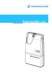
tourguide UHF
Instructions for use
1
Thank you for choosing Sennheiser!
We have designed this product to give you reliable operation over
many years. Over half a century of accumulated expertise in the
design and manufacture of high-quality electro-acoustic equipment
have made Sennheiser a world-leading company in this field.
Please take a few moments to read these instructions carefully, as we
want you to enjoy your new Sennheiser products quickly and to the
fullest.
Content
The tourguide UHF system . . . . . . . . . . . . . . . . . . . . . . . . . . . . . . . . . .5
System components . . . . . . . . . . . . . . . . . . . . . . . . . . . . . . . . . . . . . . .5
Safety instructions . . . . . . . . . . . . . . . . . . . . . . . . . . . . . . . . . . . . . . . .6
Safety instructions for handling rechargeable batteries . . . . . . . . . . . . . . . . . . . 6
EK 1038 receiver . . . . . . . . . . . . . . . . . . . . . . . . . . . . . . . . . . . . . . . . . . .7
Special features . . . . . . . . . . . . . . . . . . . . . . . . . . . . . . . . . . . . . . . . . . . . . . . . . . . . . .
Operating controls . . . . . . . . . . . . . . . . . . . . . . . . . . . . . . . . . . . . . . . . . . . . . . . . . . .
Indications . . . . . . . . . . . . . . . . . . . . . . . . . . . . . . . . . . . . . . . . . . . . . . . . . . . . . . . . . .
Preparing for use . . . . . . . . . . . . . . . . . . . . . . . . . . . . . . . . . . . . . . . . . . . . . . . . . . . . .
7
7
8
9
Using the receiver . . . . . . . . . . . . . . . . . . . . . . . . . . . . . . . . . . . . . . . 11
The operating menu of the receiver . . . . . . . . . . . . . . . . . . . . . . . . . . . . . . . . . . . 13
Configure the receiver . . . . . . . . . . . . . . . . . . . . . . . . . . . . . . . . . . . . . . . . . . . . . . . 13
Operating menu of the receiver . . . . . . . . . . . . . . . . . . . . . . . . . . . . . . . . . . . . . . . 17
Adjustment tips for the setup menu . . . . . . . . . . . . . . . . . . . . . . . . . . . . . . . . . . . 18
Locking channels for the user . . . . . . . . . . . . . . . . . . . . . . . . . . . . . . . . . . . . . . . . . 19
Adjusting the squelch threshold . . . . . . . . . . . . . . . . . . . . . . . . . . . . . . . . . . . . . . 19
Limiting the volume at the headphone output . . . . . . . . . . . . . . . . . . . . . . . . . . 20
L 2015 quick charger . . . . . . . . . . . . . . . . . . . . . . . . . . . . . . . . . . . . . 21
Special features . . . . . . . . . . . . . . . . . . . . . . . . . . . . . . . . . . . . . . . . . . . . . . . . . . . . . 21
Operating controls . . . . . . . . . . . . . . . . . . . . . . . . . . . . . . . . . . . . . . . . . . . . . . . . . . 22
Preparing for use . . . . . . . . . . . . . . . . . . . . . . . . . . . . . . . . . . . . . . . . . . . . . . . . . . . . 23
Using the charger . . . . . . . . . . . . . . . . . . . . . . . . . . . . . . . . . . . . . . . . . . . . . . . . . . . 24
Care and maintenance . . . . . . . . . . . . . . . . . . . . . . . . . . . . . . . . . . . . . . . . . . . . . . . 24
The channel bank system . . . . . . . . . . . . . . . . . . . . . . . . . . . . . . . . . . . . . . . . . . . . 25
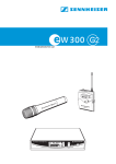
SKM 100 G2 / SKM 300 G2 / SKM 500 G2 radiomicrophones . . 27
Delivery includes . . . . . . . . . . . . . . . . . . . . . . . . . . . . . . . . . . . . . . . . . . . . . . . . . . . . 27
Operating Controls . . . . . . . . . . . . . . . . . . . . . . . . . . . . . . . . . . . . . . . . . . . . . . . . . . 27
Preparing for use . . . . . . . . . . . . . . . . . . . . . . . . . . . . . . . . . . . . . . . . . . . . . . . . . . . . 28
Using the radiomicrophone . . . . . . . . . . . . . . . . . . . . . . . . . . . . . . . . . . . . . . . . . . . 30
Care and maintenance . . . . . . . . . . . . . . . . . . . . . . . . . . . . . . . . . . . . . . . . . . . . . . . 31
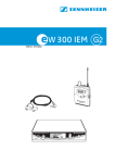
SK 100 G2 / SK 300 G2 / SK 500 G2 bodypack transmitters . . . 32
Delivery includes . . . . . . . . . . . . . . . . . . . . . . . . . . . . . . . . . . . . . . . . . . . . . . . . . . . . 32
Operating Controls . . . . . . . . . . . . . . . . . . . . . . . . . . . . . . . . . . . . . . . . . . . . . . . . . . 32
Preparing for use . . . . . . . . . . . . . . . . . . . . . . . . . . . . . . . . . . . . . . . . . . . . . . . . . . . . 33
Using the bodypack transmitter . . . . . . . . . . . . . . . . . . . . . . . . . . . . . . . . . . . . . . 35
SKP 100 G2 / SKP 500 G2 plug-on transmitters . . . . . . . . . . . . . . 36
Delivery includes . . . . . . . . . . . . . . . . . . . . . . . . . . . . . . . . . . . . . . . . . . . . . . . . . . . . 36
Operating Controls . . . . . . . . . . . . . . . . . . . . . . . . . . . . . . . . . . . . . . . . . . . . . . . . . . 36
Preparing for use . . . . . . . . . . . . . . . . . . . . . . . . . . . . . . . . . . . . . . . . . . . . . . . . . . . . 37
LC display panel of the evolution wireless transmitters, G 2 . . . 39
3
The operating menu of the transmitters
evolution wireless series G 2 . . . . . . . . . . . . . . . . . . . . . . . . . . . . . . . 41
Overview of menus . . . . . . . . . . . . . . . . . . . . . . . . . . . . . . . . . . . . . . . . . . . . . . . . . 41
The buttons . . . . . . . . . . . . . . . . . . . . . . . . . . . . . . . . . . . . . . . . . . . . . . . . . . . . . . . . 41
Working with the operating menu . . . . . . . . . . . . . . . . . . . . . . . . . . . . . . . . . . . . 42
Overview of the operating menu of the transmitters . . . . . . . . . . . . . . . . . . . . 44
Adjustment tips for the operating menu . . . . . . . . . . . . . . . . . . . . 46
Switching between channel banks . . . . . . . . . . . . . . . . . . . . . . . . . . . . . . . . . . . . 46
Switching between the channels in a channel bank . . . . . . . . . . . . . . . . . . . . . . 46
Selecting the frequencies to be stored in the channel bank “U” . . . . . . . . . . . 46
Adjusting the sensitivity . . . . . . . . . . . . . . . . . . . . . . . . . . . . . . . . . . . . . . . . . . . . . 46
Switching the phantom powering on/off
(SKP 500 G2 only) . . . . . . . . . . . . . . . . . . . . . . . . . . . . . . . . . . . . . . . . . . . . . . . . . . . 47
Selecting the standard display . . . . . . . . . . . . . . . . . . . . . . . . . . . . . . . . . . . . . . . . 48
Entering a name . . . . . . . . . . . . . . . . . . . . . . . . . . . . . . . . . . . . . . . . . . . . . . . . . . . . 48
Loading the factory-preset default settings . . . . . . . . . . . . . . . . . . . . . . . . . . . . 48
Activating/deactivating the pilot tone transmission (PILOT) . . . . . . . . . . . . . 49
Activating/deactivating the lock mode . . . . . . . . . . . . . . . . . . . . . . . . . . . . . . . . 49
Exiting the operating menu . . . . . . . . . . . . . . . . . . . . . . . . . . . . . . . . . . . . . . . . . . 49
Troubleshooting . . . . . . . . . . . . . . . . . . . . . . . . . . . . . . . . . . . . . . . . . 50
Error checklist . . . . . . . . . . . . . . . . . . . . . . . . . . . . . . . . . . . . . . . . . . . . . . . . . . . . . . 50
Recommendations and tips . . . . . . . . . . . . . . . . . . . . . . . . . . . . . . . 51
HDX noise reduction . . . . . . . . . . . . . . . . . . . . . . . . . . . . . . . . . . . . . . 52
Accessories and spare parts . . . . . . . . . . . . . . . . . . . . . . . . . . . . . . . 53
EK 1038 receiver . . . . . . . . . . . . . . . . . . . . . . . . . . . . . . . . . . . . . . . . . . . . . . . . . . . . 53
L 2015 quick charger . . . . . . . . . . . . . . . . . . . . . . . . . . . . . . . . . . . . . . . . . . . . . . . . 53
Transmitters of the evolution wireless series, G 2 . . . . . . . . . . . . . . . . . . . . . . . 53
Specifications . . . . . . . . . . . . . . . . . . . . . . . . . . . . . . . . . . . . . . . . . . . . 55
EK 1038 receiver . . . . . . . . . . . . . . . . . . . . . . . . . . . . . . . . . . . . . . . . . . . . . . . . . . . . 55
L 2015charger . . . . . . . . . . . . . . . . . . . . . . . . . . . . . . . . . . . . . . . . . . . . . . . . . . . . . . 56
Plug-in mains units . . . . . . . . . . . . . . . . . . . . . . . . . . . . . . . . . . . . . . . . . . . . . . . . . . 56
evolution wireless transmitters, G 2 . . . . . . . . . . . . . . . . . . . . . . . . . . . . . . . . . . . 57
Channel assignment . . . . . . . . . . . . . . . . . . . . . . . . . . . . . . . . . . . . . 58
4
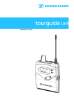
The tourguide UHF system
The tourguide UHF system consists of the EK 1038 receiver in
combination with a transmitter of the evolution wireless series G2.
The system offers optimum speech transmission for guided tours
and interpretation applications with one or several speakers. The
use of RF transmission allows freedom of movement for all
members of the group. Due to the possibility of combining the
EK 1038 receiver with different transmitters, the system can be
optimally adapted to your individual needs.
The system has superb audio quality with an increased signal-tonoise ratio and dynamic range due to the inclusion of Sennheiser’s
HDX noise reduction system.
System components
The components of the system are:
y EK 1038 receiver
y BA 2015 accupack
y L 2015 charger
y NT 1 or NT 3 plug-in mains unit
y GP 03 headphones with stereo jack plug
y transmitter (please specify when ordering)
5
Safety instructions
Never open an electronic unit! If units are opened by customers in
breach of this instruction, the warranty becomes null and void.
Use the unit in dry rooms only.
Use a damp cloth for cleaning the unit. Do not use any cleansing
agents or solvents.
Safety instructions for handling rechargeable batteries
When used properly, rechargeable batteries are a safe and reliable
energy source.
However, if abused or misused, rechargeable batteries may leak
and, in extreme cases, may even present an explosion and fire
hazard. Please understand that Sennheiser does not accept liability
for damage arising from abuse or misuse. Especially observe the
following safety instructions:
y Observe correct polarity.
y Never short-circuit rechargeable batteries.
y Do not throw rechargeable batteries into fire.
y Never heat rechargeable batteries.
y Do not mutilate or dismantle rechargeable batteries.
y To protect the environment, dispose of batteries that are no
longer usable as special waste or return them to your specialist
dealer.
y Store rechargeable batteries in a safe place and keep them away
from children.
6
EK 1038 receiver
Special features
The EK 1038 receiver is a small and reliable bodypack receiver that
can easily be attachted to the clothing by the means of a belt clip.
16 factory-preset UHF frequencies which are intermodulation-free
and four freely selectable frequencies ensure a high level of
flexibility and operational reliability. In combination with the HDX
noise reduction it provides for a safe transmission.
The receiver is characterized by
y Easy use
y Channel-indication via display
y Channel adjustment via rocker button
y LED operation indication
y LED and display “LowBattery” indication
y LED receiving indication
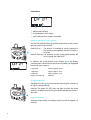
Operating controls
Volume control and On/Off button
SET button
3.5 mm jack socket for headphones
/ rocker button (UP/DOWN)
Receiving antenna
Battery compartment cover
Red LED for operation and battery status indication (LOW BATT/ON)
Green LED for RF signal indication
Charging cotacts
Battery compartment cover
Unlocking button
ESC button
Display
7
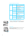
Indications
햴
Alphanumeric display
4-step battery status display
Lock mode icon (lock mode is activated)
Operation and battery status indication
The red LED (LOW BAT/ON) provides information on the current
operating state of the receiver:
Red LED lit up:
The receiver is switched on and the capacity of
the batteries/rechargeable battery BA 2015 is
sufficient.
Red LED flashing: The batteries are/the rechargeable battery BA
2015 is going flat (LOW BAT)!
In addition, the 4-step battery status display on the display
panel provides information on the remaining battery/rechargeable
battery BA 2015 capacity:
3 segments:
2 segments:
1 segment:
Battery icon flashing:
capacity approx. 100 %
capacity approx. 70 %
capacity approx. 30 %
LOW BAT
RF signal indication
The green LED (RF) at the front of the receiver lights up when an
RF signal is being received.
However, the green LED (RF) does not light up when the audio
output is muted because the RF signal of the received transmitter is
too weak.
Display backlighting
After pressing a button, the display remains backlit for approx. 15
seconds.
8
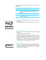
Preparing for use
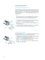
Inserting and changing the battery pack/batteries
For powering the units, we recommend using the supplied BA 2015
battery pack. The battery pack can be recharged in the L 2015
charger while remaining in the receiver (see “Charging the
rechargeable battery BA 2015” on page 24).
Accupacks ensure economical and environmentally friendly
operation of the tourguide UHF system during daily use.
If no power supply is available for recharging the battery pack, you
can alternatively use 1.5 V AA size batteries.
Press the two unlocking buttons and open the battery
compartment cover .
Insert the battery pack or the batteries as shown on the left.
Please observe correct polarity when inserting the battery pack
or the batteries.
Close the battery compartment. The battery compartment
cover locks into place with an audible click.
How to properly use the battery pack or the batteries
For battery pack operation, only use the BA 2015 battery pack in
order to ensure optimum operational reliability. Batteries and
rechargeable battery cells have different discharging curves. The
receiver is able to identify the BA 2015 battery pack and to use it to
full capacity. It also adapts the battery status display according to
the type of power supply used (batteries or battery pack).
Individual rechargeable battery cells will not be identified as
battery packs.
After use (e.g. during the night), charge the BA 2015 battery
pack of the receiver in the L 2015 charger. The charging time is
approx. 2.5 hours, at which time the unit then switches to trickle
charging.
If you do not use the receiver for extended periods of time (e.g.
while you are on holiday), remove the battery pack or the
batteries. After three months at the latest, the battery packs will
need a refresh charge in the L 2015 charger. This prevents
damage to the battery pack due to self-discharge.
9
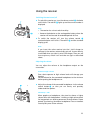
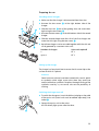
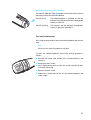
Connecting the headphones
You must only connect headphones with a stereo jack plug and a
minimum impedance of 8 Ω to the receiver.
10
Connect the headphones to the receiver’s 3.5 mm jack socket
(PHONES) .
Using the receiver
Switching the receiver on/off
To switch the receiver on, turn the volume control clockwise
until it clicks. The red LED lights up and the current number is
displayed.
Note:
y The receiver has a short switch-on delay.
y Remove the batteries or the rechargeable battery when the
receiver will not be used for extended periods of time.
To switch the receiver off, turn the volume control counterclockwise until it clicks. The red LED and the standard
display go off.
Note:
If you insert the active receiver into the L 2015 charger to
recharge it, the receiver automatically gets off. It even remains
inactivated when you take it out of the charger. Then you will
have to primary switch it off and then on again as described
above.
Adjusting the volume
You can adjust the volume at the headphone output on the
transmitter.
Attention! High volume!
Even short exposure to high volume levels will damage your
hearing!
Set the volume for the connected headphones to the minimum
before putting the headphones on.
Adjust the volume of the connected headphones via the volume
control button so that you can clearly and precisely
understand the speaker.
Volume up? – NO!
When people use headphones, they tend to choose a higher
volume than with loudspeakers. Listening at high volume levels
for long periods can lead to permanent hearing defects. Please
protect your hearing, Sennheiser headphones have an excellent
sound quality even at low volumes.
11
Switching the channel
If several guided tours take place within a building and several
transmission links are operated at the same time, the user can
switch the channel of the receiver to the channel that is stated by
the guide.
Note:
It is only possible to switch the channel if the lock mode is
deactivated. If it is deactivated, no lock mode icon appears on
the display (see “Activating/deactivating the lock mode” on
page 18).
햴
Use the / rocker button (UP/DOWN) to switch between
the 20 channels maximum.
The number of selectable channels might be limited when the
operator has locked several channels (see “Locking channels for
the user” on page 19). Locked channels are not displayed.
The receiver immediately switches to the new channel. If a
transmission signal is received on the new channel the green
LED lights up.
Attaching the receiver to clothing
The receiver is attached to clothing (e.g. belt, waistband) with
the supplied belt clip.
12
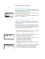
The operating menu of the receiver
The operationg menu of the receiver consists of the user menu and
the setup menu.
Within the user menu, the user can switch between the channels via
the / rocker button (see “Switching the channel” on page 12).
Within the setup menu, the operator can configure the receiver for
daily use.
Configure the receiver
SETUP
This section describes how to use the setup menu. An overview over
the menu is given within the chapter “The setup menu of the
receiver” on page 17.
Starting the setup menu
In order to get into the configuration menu, the receiver must be
switched off.
Open the battery compartment.
Press the SET button and keep it pressed.
At the same time, turn the volume control clockwise until it
clicks to switch the receiver on. The “SETUP” display appears on
the display panel.
13
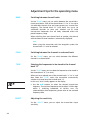
Function of the buttons in the setup menu
Buttons
SET
Mode
To ...
Start display
get from the start display
“SETUP“ to the operating menu
of the setup menu
Operating menu get into the setting mode of the
selected menu
/
Setting mode
store the settings and return to
the top menu level
Start display
without function
Operating menu change to the previous menu ()
or change to the next menu ()
ESC
Setting mode
adjust the setting of the selected
menu:
option (/)
Start display
without function
Operating menu cancel the adjustment and return
to the start display “SETUP“
Setting mode
cancel the entry and return to the
start display “SETUP“
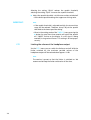
Getting into the operating menu of the setup menu
Press the SET button to get from the start display into the
operating menu. The first menu “LOCK” flashes on the display.
Selecting a menu
Press the / rocker button (UP/DOWN) to select the menu you
would like to adjust the setting.
The current setting that can be adjusted flashes on the display.
14
The setup menu comprises four menus that can be chosen in the
following order:
Display
LOCK
TUNE
SQELCH
LTD
Function of the menu
Activating/deactivating the lock mode (see page 18)
Setting a receiving frequency for the channels (see
page 18) and locking channles for the user (see
page 19)
Adjusting the squelch threshold (see page 19)
Acitvating/deactivating the limiter at the headphone
output (see page 20)
Getting into the setting mode of a menu
Press the SET button to get into the setting mode of the
selected menu.
The current setting that can be adjusted flashes on the display.
Adjusting a setting
Press the / (UP/DOWN) rocker button to adjust the setting
of the menu.
The new setting flashes on the display.
By briefly pressing the rocker button, the display jumps either
forwards or backwards to the next setting. In the “TUNE” menu,
the rocker button features a “fast search” function: If you hold
down the or button, the display cycles continuously,
allowing you to get fast and easily to your desired setting. The
new setting flashes on the display until it is stored.
Storing a setting
Press the SET button to store the setting. “STORED” appears on
the display, indicating that the setting has been stored. You
return to the operating menu of the setup menu. The last menu
selected flashes on the display.
15
Canceling the entry
Press the ESC button to cancel the entry. With the menus “LOCK“,
“SQUELCH“ and “LTD“ you return to the start display “SETUP“. The
last menu remains unchanged.
An exception is the “TUNE“ menu. When canceling the entry with
this menu, you will stay in the setting mode of the menu but you
return to the display of the current channel (e.g. “CH 01“). It is then
possible to restart your entry.
Exiting the setup menu
Switch the receiver off to exit the setup menu. To do so, turn the
volume control counterclockwise until it clicks
If you then restart the receiver you get into the user menu and
the current channel is displayed.
16
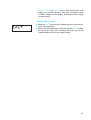
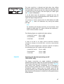
Operating menu of the receiver
USER MENU
The user menu of the receiver
Changing the channel
/ : channel
01...20
The setup menu of the receiver
Operating menu
Starting display
Setting mode
SET
Configure the
receiver
SET
ESC
LOC. OFF
LOC. ON
Lock mode activated
or deactivated
Locking operation
/
: ON, OFF
SET
STORED
SET
ESC
CH 01
CH 20
Current channel
Change frequencies
of the channels
/
: channel 01...20
SETUP MENU
SET
833.125 MHz
/
: Receiving frequency
in steps of 25-kHz,
"– – –.– – – MHz" to
lock channel
STORED
SET
ESC
SET
SQ LO
Current setting of
squelch threshold
Adjusting the
squelch threshold
833.100 MHz
current fraquency of
selected channel
SQ MID
: SQ LO, SQ MID,
/
SQ HI, SQ OFF
hold 3 sec: "SQ OFF"
SET
STORED
SET
ESC
Limiting the volume of
headphone output
LTD.OFF
Limiter activated or
deactivated
STORED
LTD.ON
/
: ON, OFF
SET
17
Adjustment tips for the setup menu
LOCK
Activating/deactivating the lock mode
Via the “LOCK” menu, you can activate or deactiveate the lock
mode. This mode locks the / rocker button (UP/DOWN) so that
the user cannot change the preset channel.
The lock mode icon on the display of the user interface (user menu)
indicates that the lock mode is activated.
To deactivate the lock mode you have to select “LOC.OFF“ within the
menu “LOCK“ of the setup menu.
햴
TUNE
Changing the receiving frequencies of the channels
Via the “TUNE“ menu you can change the receiving frequency of a
channel or you scan lock certain channels (see “Locking channels for
the user” on page 19).
16 of 20 channels do have factory-preset receiving frequencies.
These frequencies do not cause any intermodulation interferences
and they ensure a safe and trouble-free reception even if several
transmission links are operated simultaneously.
Note:
The receiving frequency of the receiver must exactly correspond
to the transmission frequency of the transmitter!
Select the “TUNE“ menu to change these frequencies or to enter
the receiving frequencies for the channels 17 to 20.
The current channel is flashes on the display.
Use the / rocker button (UP/DOWN) to select the channel
whose frequency you would like to change.
The selected channel flashes on the display.
Press the SET button to confirm your selection.
The current receiving frequency of the selected channel flashes
on the display.
Use the / rocker button to select the desired receiving
frequency. Receiving frequencies are tunable in 25-kHz steps
The selected receiving frequency flashes on the display.
Press the SET button to store the new receiving frequency.
18
TUNE
Locking channels for the user
Via the “TUNE“ menu you can lock certain channels so that the user
cannot select them. This makes sense when several guided tours take
place at the same time and several transmission links are operated
simultaneously. As only the selectable channels are displayed, the
user can quickly switch to the channel stated by the guide.
Select the channel you like to lock as described within the chapter
“Changing the receiving frequencies of the channels” on page 18 and
confirm your selection by pressing the SET button.
The current receiving frequency of the selected channel flashes on
the display.
Use the / rocker button (UP/DOWN) to select the character
string “---.---“. This string follows the frequency 866.000 MHz and
precedes 830.000 MHz.
Press the SET button to store your setting.
This channel is now locked is no longer displayed for the user.
Releasing locked channels
Via the “TUNE“ menu you can release locked channels.
Select the channel that you would like to release.
Use the / rocker button (UP/DOWN) to select the frequency
that you would assign to the channel.
Press the SET button to store the setting.
The user can now select the channel again.
SQELCH
Adjusting the squelch threshold
The receiver is equipped with a squelch that can be adjusted via the
“SQELCH” menu. The squelch eliminates annoying noise when the
transmitter is switched off. It also suppresses sudden noise when
there is no longer sufficient transmitter power received by the
receiver.
Note:
Before adjusting the squelch threshold to a different setting, use
the volume control to set the volume for the connected
headphones to the minimum.
There are three possible squelch settings:
y SQ LO = low
y SQ MID = middle
y SQ HI = high
19
Selecting the setting “SQ LO” reduces the squelch threshold,
selecting the setting “SQ HI” increases the squelch threshold.
Adjust the squelch threshold – with the transmitter switched off
– to the lowest possible setting that suppresses hissing noise.
IMPORTANT!
Note:
y If the squelch threshold is adjusted too high, the transmission
range will be reduced. Therefore, always adjust the squelch
threshold to the lowest possible setting.
y When in the setting mode of the “SQELCH” menu, pressing the
button for more than three seconds will switch the squelch
off. “SQ.OFF” flashes on the display. If no RF signal is being
received, hissing noise will occur. This setting is for test purposes only.
LTD
Limiting the volume at the headphone output
Via the “LTD” menu, you can switch the limiter on and off. With the
limiter switched on, the maximum possible volume of the
headphone output will be reduced about approx. 15 dB.
Note:
The receiver is preset so that the limiter is switched on. We
recommend to keep the limiter switched on all the time.
20
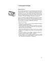
L 2015 quick charger
Special features
The L 2015 quick charger must only be used for automatically charging BA 2015 battery packs – individual rechargeable battery cells
or primary cells cannot be charged! The BA 2015 battery pack is
delivered as accessory with the EK 1038 receiver and fits to the
Sennheiser bodypack receivers ew series G2 as well (see “SK 100 G2
/ SK 300 G2 / SK 500 G2 bodypack transmitters” on page 32).
The EK 1038 receiver and the SK bodypack transmitters have charging contacts on their sides and can thus be charged with the accupack inserted in the L 2015 charger. When placed into the charger,
the transmitters and receiver automatically switch off.
Features of the charger:
y Quick charge in approx. 2½ hours (with completely discharged
y
y
y
y
accupacks and room temperature).
Automatic detection of full charge and subsequent switching to
trickle charge so the accupacks can remain in the charger even
when they have been fully charged.
Highest possible operational reliability, since correct insertion,
temperature and voltage of the accupacks are monitored during
charging.
Up to two accupacks can be charged – optionally separately or
inserted in the transmitter or receiver – separatly.
Several chargers can be cascaded together to form a larger
charging station which can be powered by a common mains unit
(see “Accessories and spare parts” on page 53).
21
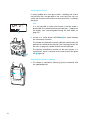
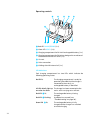
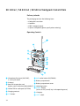
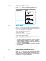
Operating controls
Red LED CHARGE/ERROR (2 x)
Green LED READY (2 x)
Charging compartment for BA 2015 rechargeable battery (2 x)
Charging compartment for EK 1038 or bodypack transmitters of
the evolution wireless G2 series (2 x)
Air vent
Mains connection
Guiding slot with internal rail (2 x)
LED indications
Each charging compartment has two LEDs which indicate the
following operating states:
No LED lit:
The charging compartment is ready for
operation (provided that the charger is
connected to the mains), no
rechargeable battery is identified.
All LEDs briefly light up The charger has been connected to the
one after the other:
mains and is carrying out a self test.
22
Red LED lit:
The rechargeable battery is being
charged.
Red LED flashing:
A problem has occured (see
”Troubleshooting“ on page 50).
Green LED lit:
The rechargeable battery is fully
charged and the charger has switched
to trickle charging.
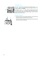
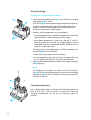
Preparing for use
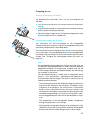
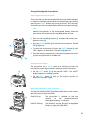
Cascading several chargers
Make sure that the charger is disconnected from the mains.
Unscrew the two screws at the right bottom side of the
charger.
Slide the two rails out of the guiding slots and screw them
tight using the two screws .
Unscrew the two screws at the left bottom side of the second
charger.
Slide the second charger onto the rails of the first charger and
screw the rails tight using the two screws .
Up to three chargers can be cascaded together with the rails and
can by powered by a common mains unit..
Numbers of chargers
1
up to 3
Mains unit requiredl
NT 1
NT 3
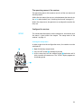
Setting up the charger
The charger has four plastic feet to ensure that it cannot slip on the
surface on which it is placed.
Attention!
Some furniture surfaces have been treated with varnish, polish
or synthetics which might cause stains when they come into
contact with other synthetics. Despite a thorough testing of the
synthetics used by us, we cannot rule out the possibility of
staining.
Switching the charger on or off
To switch the charger on, insert the hollow jack plug on the cable
of the mains unit (mains unit must be ordered separately) into
socket .
Connect the mains unit to the mains.
All LEDs briefly light up one after the other.
23
Using the charger
Charging the rechargeable battery BA 2015
Insert the rechargeable battery into one of the two charging
compartments as shown.
The red LED at the occupied charging compartment lights up.
Charging a completely discharged rechargeable battery takes
approx. 2½ hours at room temperature. It is normal for the
accupacks to get warm during charging.
However, the charging process may take longer if:
y the rechargeable battery is deep-discharged and first has to be
reconditioned by a deep discharge recovery charge,
y the ambient temperature is close to or over 40 °C, since, in
order to protect the accupack, the charging process will be
interrupted until the rechargeable battery temperature has
fallen to an admissible value.
For safety reasons, the charging process will be interrupted and
the red LED will start flashing if:
y excessively hot accupacks cannot cool down,
y an rechargeable battery cannot be fully charged within the
max. charging time of 6 hours, e.g. due to overaged cells.
After the rechargeable battery has been fully charged, the green
LED lights up.
Note:
For charging, the accupacks can remain in the unit. Place the
unit with the rechargeable battery inserted into the charging
compartment as shown. The receiver or the transmitter automatically switch off.
Care and maintenance
24
Use a slightly damp cloth to clean the switched-off charger from
time to time. Use a brush or similar to remove dust from the
charging compartments. Do not use any cleansing agents or
solvents.
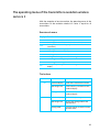
Suitable transmitters of the
evolution wireless series, G 2
The EK 1038 bodypack receiver matches any of the transmitters
(range E) of the Sennheiser evolution wireless series G 2:
y Radiomicrophones:
SKM 100 G2 / SKM 300 G2 / SKM 500 G2
y Bodypack transmitters: SK 100 G2 / SK 300 G2 / SK 500 G2
y Plug-on transmitters: SKP 100 G2 / SKP 500 G2
The SK 2015 bodypack transmitter of the 2015 system from the
domain of audiology also fits to the EK 1038 bodypack receiver.
Note:
To put the system into operation, transmitter and receiver must
be set to the same frequency!
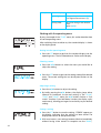
The channel bank system
The system is available in the UHF frequency range from 830 to
866 MHz with 1440 transmission frequencies. Transmitters that are
to be combined with the EK 1038 bodypack receiver thus have to
use the following transmission range:
Range E:
830 to 866 MHz
The transmitters have nine channel banks with up to 20 channels
each.
channel
bank
Kanalbank
1... 1...
8 8
channel
bank
Kanalbank
U U
channel
1
Kanal
1
preset frequency
Voreingestellte
Frequenz
channel
2
Kanal
2
preset frequency
Voreingestellte
Frequenz
channel
Kanal
20 20
preset frequency
Voreingestellte
Frequenz
channel
1
Kanal
1
freely selectable
frequency
Frei wählbare
Frequenz
channel
2
Kanal
2
freely selectable
frequency
Frei wählbare
Frequenz
channel
Kanal
20 20
freely selectable
frequency
Frei wählbare
Frequenz
Each of the channels in the channel banks “ 1” to “8” has been
factory-preset to a transmission frequency (see enclosed frequency
table). These transmission frequencies cannot be changed but have
been preset so that e.g. country-specific regulations on frequency
usage are taken into account.
25
The channel bank “U” (user bank) allows you to store your selection
out of 1440 transmission frequencies that are freely selectable
within the preset frequency range.
Note:
The tourguide frequencies are preset on the channel bank “8”.
26
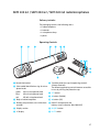
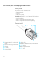
SKM 100 G2 / SKM 300 G2 / SKM 500 G2 radiomicrophones
Delivery includes
The packaging contains the following items:
y 1 radiomicrophone
y 2 batteries
y 1 microphone clamp
y 1 pouch
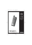
Operating Controls
Turnable protective cap for operating controls
(shown removed)
Color-coded identification ring for microThe following operating controls become accessible
phone heads
in turn by turning the protective cap:
green: MD 835 microphone head
SET button
blue:
MD 845 microphone head
button (DOWN)
red:
ME 865 microphone head
button (UP)
Body of radiomicrophone
Sound inlet basket
Battery compartment (not visible from
outside)
Red LED for operation and
battery status indication (ON/LOW BAT)
Display section
ON/OFF button
LC display
MUTE switch
27
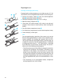
Preparing for use
Inserting and changing the battery
For powering the radiomicrophone, you can either use two 1.5 V AA
size batteries or the rechargeable Sennheiser BA 2015 battery pack.
Unscrew the display section from the radiomicrophone’s
body by turning it counter-clockwise.
Slide back the display section as far as it will go.
Open the battery compartment .
Insert the 9 V PP3 alkaline battery (IEC 6 LR 61) or the BA 2015
accupack. Please observe correct polarity when inserting the
battery.
Close the battery compartment cover .
Push the battery compartment into the radiomicrophone’s body.
Screw the display section tight.
Note:
For rechargeable battery operation of the receiver, only use the
BA 2015 rechargeable battery In order to ensure optimum operational reliability. For charging the accupack, only use the L
2015 charger. Both the rechargeable battery and the charger are
available as accessories. The rechargeable battery is fitted with
an integrated sensor which is – via a third contact – monitored
by the electronics of the receiver and the charger. The sensor is
necessary for the following control purposes:
y The taking into account of the different voltage characteristics
of primary cells (batteries) and accupacks. The battery status
indications on the displays, the transmission of transmitter
battery status information to the rack-mount receivers and
the switch-off thresholds at the end of the operating time are
corrected correspondingly. Due to the missing sensor, individual rechargeable battery cells will not be identified as accupacks.
y The monitoring of the rechargeable battery temperature
during charging in the L 2015 charger.
28
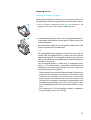
Changing the microphone module
First remove the battery or the rechargeable battery and leave
the radiomicrophone open.
Unscrew the sound inlet basket.
Remove the screw and put it to one side.
Remove the microphone module by pulling it out of the housing
as shown. Do not touch the contacts!
Insert the new module.
Secure the capsule by tightening the screw.
Note:
The screw mechanically secures the microphone capsule. If the
screw is missing, malfunctions may occur during tough use.
Put on the sound inlet basket and identification ring supplied
with the new microphone headand screw it tight.
Insert the batteries/accupack.
Close the radiomicrophone and put it into operation.
Note:
Microphone capsule, sound inlet basket and foam insert form an
acoustic unit and must therefore always be exchanged all
together. Each microphone head comes with a color-coded
identification ring to distinguish different microphone heads
from each other (green = MD 835, blue = MD 845, red = ME 865).
29
Using the radiomicrophone
Switching the radiomicrophone on/off
The radiomicrophone can only be switched off when the standard
display is shown on the display panel. When in the operating menu,
briefly pressing the ON/OFF button will cancel your entry (ESC
function) and return you to the standard display with the last
stored settings.
Note:
Remove the batteries or the rechargeable battery when the radiomicrophone will not be used for extended periods of time.
Turn the protective cap at the bottom of the radiomicrophone
so that the ON/OFF button becomes accessible.
Press the ON/OFF button to switch the radiomicrophone on. The
red LED lights up.
To switch the radiomicrophone off, press the ON/OFF button until “OFF” appears on the display. The red LED goes off.
Muting the radiomicrophone
The radiomicrophone has a MUTE switch that noiselessly mutes the
audio signal without switching the radiomicrophone off.
Turn the protective cap at the bottom of the radiomicrophone
so that the MUTE switch becomes accessible.
Set the MUTE switch to the position ’MUTE’. The “MUTE” display
appears on the radiomicrophone’s display panel.
Set the MUTE switch back to the original position to
30
retransmit the audio signal.
Operation and battery status indication
The red LED (LOW BAT/ON) provides information on the current
operating state of the radiomicrophone:
Red LED lit up:
The radiomicrophone is switched on and the
capacity of the batteries/BA 2015 rechargeable
battery is sufficient.
Red LED flashing:
The batteries are/the BA 2015 rechargeable
battery is going flat (LOW BAT)!
Care and maintenance
Use a slightly damp cloth to clean the radiomicrophone from time to
time.
Note:
Do not use any cleansing agents or solvents.
To clean the radiomicrophone’s sound inlet basket, proceed as
follows:
Unscrew the sound inlet basket (turn counterclockwise) and
remove it.
Remove the foam insert.
Use a slightly damp cloth to clean the sound inlet basket from
the inside and ouside.
Reinsert the foam insert.
Replace the sound inlet basket on the radiomicrophone and
screw it tight.
31
SK 100 G2 / SK 300 G2 / SK 500 G2 bodypack transmitters
Delivery includes
The packaging contains the following items:
y 1 bodypack transmitter
y 2 batteries
y 1 BPP 1 bodypack pouch
y 1 clip-on microphone (please specify when ordering)
Operating Controls
Microphone/line input (MIC/LINE),
3.5 mm jack socket
Antenna
/ rocker button (UP/DOWN)
Battery compartment
Battery compartment cover
Red LED for operation and
battery status indication (ON/LOW BAT) Unlocking button
ON/OFF button
Yellow LED for audio peak (AF PEAK)
(serves as ESC (cancel) key in the operating menu)
Charging contacts
LC display
SET button
MUTE switch
32
Preparing for use
Inserting and changing the battery
For powering the transmitter, two 1.5 V AA size batteries are
required.
Press the two unlocking buttons and open the battery compartment
cover .
Insert the two batteries as shown above. Please observe correct
polarity when inserting the batteries.
Close the battery compartment. The battery compartment cover
locks into place with an audible click.
Inserting and charging the accupack
The transmitter can also be powered via the rechargeable
Sennheiser BA 2015 accupack. Insert the rechargeable battery into
the battery compartment as described above.
The transmitter has two charging contacts and a sensing contact
on its short sides. The rechargeable battery can be recharged while
remaining in the transmitter. Insert the transmitter into the L 2015
charger (see ”Charging the rechargeable battery BA 2015“ on
page 24).
Note:
For rechargeable battery operation of the transmitter, only use
the BA 2015 rechargeable battery in order to ensure optimum
operational reliability. For charging the accupack, only use the
L 2015 charger. Both the rechargeable battery and the charger
are available as accessories.
The rechargeable battery is fitted with an integrated sensor
which is – via a third contact – monitored by the electronics of
the transmitter and the charger. The sensor is necessary for the
following control purposes:
y The taking into account of the different voltage characteristics
of primary cells (batteries) and accupacks. The battery status
indications on the displays, the transmission of transmitter
battery status information to the rack-mount receivers and
the switch-off thresholds at the end of the operating time are
corrected correspondingly. Due to the missing sensor, individual rechargeable battery cells will not be identified as accupacks.
y The monitoring of the rechargeable battery temperature
during charging in the L 2015 charger.
y The prevention of improper charging of inserted primary cells
(batteries). Due to the missing sensor, individual rechargeable
battery cells will also not be charged in the L 2015 charger.
33
Connecting the microphone/line cable
The microphone/line input is designed for the connection of both
condenser microphones and instruments (e.g. guitars). DC
powering of the condenser microphones is via the microphone/line
input.
Connect the 3.5 mm jack plug from the microphone/line cable
to the 3.5 mm jack socket (MIC/LINE) .
Lock the 3.5 mm jack plug by screwing down the coupling
ring Via the operating menu, adjust the sensitivity of the micro-
phone/line input (MIC/LINE).
Attaching the microphones
Use the microphone clips to attach the ME 2 or ME 4 clip-on
microphones to clothing (e.g. tie, lapel).
Adjust the ME 3 headmic so that a comfortable and secure fit is
ensured.
Positioning the microphones
The ME 3 and ME 4 microphones are directional microphones, i.e.
their sound inlet should always be directed towards the sound
source (e.g. mouth).
The ME 2 with omni-directional pick-up pattern picks up sound
equally from all directions. It is the best choice if movements of the
speaker’s head have to be compensated for. However, it should be
attached as close as possible to the sound source.
Adjust the sensitivity correctly for all microphones/usages (see
”Adjusting the sensitivity“ on page 46).
Attaching the transmitter to clothing
The transmitter is attached to clothing (e.g. belt, waistband) with
the supplied belt clip.
The clip is detachable so that you can also attach the transmitter
with the antenna pointing downwards. To do so, withdraw the clip
from its fixing points and attach it the other way round.
The supplied BPP 1 bodypack pouch helps to protect the transmitter
against moisture.
34
Using the bodypack transmitter
Switching the transmitter on/off
The transmitter can only be switched off when the standard display
is shown on the display panel. When in the operating menu, briefly
pressing the ON/OFF button will cancel your entry (ESC function)
and return you to the standard display with the last stored settings.
Note:
Remove the batteries or the rechargeable battery when the
transmitter will not be used for extended periods of time.
Press the two unlocking buttons and open the battery com-
partment cover .
Press the ON/OFF button to switch the transmitter on. The red
LED lights up.
To switch the transmitter off, press the ON/OFF button until
“OFF” appears on the display. The red LED goes off.
Close the battery compartment. The battery compartment cover
locks into place with an audible click.
Muting the transmitter
The transmitter has a MUTE switch that noiselessly mutes the
transmitter’s audio signal without switching the transmitter off.
Set the MUTE switch to the position ’MUTE’. The “MUTE”
display appears on the display panel.
Set the MUTE switch back to the original position to
retransmit the audio signal.
Operation and battery status indication
The red LED (LOW BAT/ON) provides information on the current
operating state of the transmitter:
Red LED lit up:
The transmitter is switched on and the
capacity
of
the
batteries/BA 2015
rechargeable battery is sufficient.
Red LED flashing:
The batteries are/the BA 2015 rechargeable
battery is going flat (LOW BAT)!
35
SKP 100 G2 / SKP 500 G2 plug-on transmitters
Delivery includes
The packaging contains the following items:
y 1 plug-on transmitter
y 2 batteries
y 1 POP 1 plug-on pouch
Suitable microphones (to be ordered separately) for the plug-on
transmitter:
y Dynamic microphones
y Condenser microphones with internal power supply
y Condenser microphones with 48 V phantom powering
Operating Controls
Microphone input, XLR-3 socket, (unba- lanced)
Mechanical locking ring of XLR-3 socket
LC display
SET button
button (DOWN)
36
button (UP)
Red LED for operation and battery status indication
ON/OFF button
Battery compartment cover
MUTE switch
Preparing for use
Inserting and changing the battery
For powering the plug-on transmitter, you can either use two 1.5 V
AA size batteries or the rechargeable Sennheiser BA 2015 accupack.
Slide the battery compartment cover in the direction of the
embossed arrow until it clicks audibly and open the cover.
Insert the two batteries or the BA 2015 rechargeable battery as
shown below. Please observe correct polarity when inserting the
batteries/accupack.
Close the battery compartment. The battery compartment cover
9 locks into place with an audible click.
Note:
For rechargeable battery operation of the transmitter, only use
the BA 2015 rechargeable battery in order to ensure optimum
operational reliability. For charging the accupack, only use the L
2015 charger. Both the rechargeable battery and the charger are
available as accessories.
The rechargeable battery is fitted with an integrated sensor
which is – via a third contact – monitored by the electronics of
the plug-on transmitter and the charger. The sensor is necessary
for the following control purposes:
y The taking into account of the different voltage characteristics
of primary cells (batteries) and accupacks. The battery status
indications on the displays, the transmission of transmitter
battery status information to the rack-mount receivers and
the switch-off thresholds at the end of the operating time are
corrected correspondingly. Due to the missing sensor, individual rechargeable battery cells will not be identified as accupacks.
y The monitoring of the rechargeable battery temperature
during charging in the L 2015 charger.
37
Plugging the transmitter onto the microphone
Plug the transmitter’s XLR-3 connector onto the microphone’s
XLR-3 socket.
Tighten the locking ring .
Note:
The transmitter uses the microphone body as an antenna –
therefore only microphones with a metal casing should be used
for best signal transmission.
Betriebs- und Batterieanzeige
The red LED (LOW BAT/ON) provides information on the current
operating state of the plug-on transmitter:
Red LED lit up:
The plug-on transmitter is switched on and
the capacity of the batteries/BA 2015
rechargeable battery is sufficient.
Red LED flashing:
The
batteries
are/the
BA
2015
rechargeable battery is going flat (LOW
BAT)!
38
LC display panel of the evolution wireless transmitters, G 2
LC display panel
Alphanumeric display
“B.CH“ – appears when the channel bank and
the channel number are displayed
“MHz“ – appears when the frequency is displayed
4-step battery status display
Lock mode icon (lock mode is activated)
!
"
“PILOT” display (pilot tone transmission is activated)
! “MUTE” display (audio input is muted)
" 7-step level display for audio signal “AF”
Battery status indication
The 4-step battery status display on the display panel provides
information on the remaining battery/BA 2015 rechargeable
battery capacity:
3 segments:
2 segments:
1 segment:
Battery icon flashing:
capacity approx. 100 %
capacity approx. 70 %
capacity approx. 30 %
LOW BAT
“MUTE” display
The “MUTE” display ! appears on the display panel when the plugon transmitter is muted.
!
Modulation display
The level display for audio signal “AF” " shows the modulation of
" the plug-on transmitter.
When the audio input level is excessively high, the level display for
audio signal “AF” " shows full deflection for the duration of the
overmodulation.
39
“PILOT” display
The “PILOT” display appears on the display panel when the pilot
tone transmission is activated.
Display backlighting
After pressing a button, the display remains backlit for approx. 15
seconds.
40
The operating menu of the transmitters evolution wireless
series G 2
With the exception of one transmitter, the operating menu of the
transmitters of the evolution wireless G2 series is equal for all
transmitters.
Overview of menus
Display
Function of the menu
BANK
CHAN
Switching between channel banks
Switching between the channels in a channel bank
Setting a transmission frequency for the channel bank “U”
(user bank)
Adjusting the sensitivity (AF)
Selecting the standard display
Entering a name
Loading the factory-preset default settings
Activating/deactivating the pilot tone transmission
Activating/deactivating the lock mode
Exiting the operating menu and returning to the standard
display
TUNE
SENSIT
DISPLY
NAME
RESET
PILOT
LOCK
EXIT
The buttons
Buttons
ON
SET
Mode
To...
Standard display
switch the transmitter on and off
Operating menu
cancel the entry and return to the
standard display
Setting mode
cancel the entry and return to the
standard display
Standard display
get into the operating menu
Operating menu
get into the setting mode of the
selected menu
Setting mode
store the settings and return to the
top menu level
41
/
Standard display
without function
Operating menu
change to the previous menu ()
or change to the next menu ()
Setting mode
adjust the setting of the selected
menu:
option (/)
Working with the operating menu
By way of example of the “TUNE” menu, this section describes how
to use the operating menu.
After switching the transmitter on, the standard display is shown
on the display panel.
Getting into the operating menu
Press the SET button to get from the standard display into the
operating menu. The last selected menu flashes on the display.
Selecting a menu
Press the / buttons to select the menu you would like to
adjust the setting.
Press the SET button to get into the setting mode of the selected
menu. The current setting that can be adjusted flashes on the
display.
Adjusting a setting
Press the / buttons to adjust the setting.
By briefly pressing the / buttons, the display jumps either
forwards or backwards to the next setting. In the “CHAN”,
“TUNE” and “NAME” menu, the / buttons feature a “fast
search” function. If you hold down a button, the display cycles
continuously, allowing you to get fast and easily to your desired
setting.
Storing a setting
Press the SET button to store the setting. “STORED” appears on
the display, indicating that the setting has been stored. The
display then returns to the top menu level.
With most menus, new settings become effective immediately
without having to be stored. An exception are the “BANK”,
42
“CHAN”, “TUNE” and “RESET” menus. With these menus, new
settings only become effective after they have been stored
(“STORED” appears on the display, indicating that the setting
has been stored).
Exiting the operating menu
Select the “EXIT” menu to exit the operating menu and to return
to the standard display.
When in the operating menu, briefly pressing the ON/OFF button
will cancel your entry (ESC function) and return you to the
standard display with the last stored settings.
43
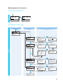
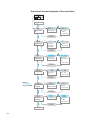
Overview of the operating menu of the transmitters
SET
EXIT
BANK
SET
Changing the channel
bank
BANK 1
BANK U
Current channel bank
/ : 1...8, U (User
Bank)
SET: Stores the setting
STORED
CHAN
SET
1.03
B.CH
Current channel
(display depends on
"DISPLY" setting)
Changing the channel
1.02
/ : Channel
B.CH
01...20
SET: Stores the setting
STORED
TUNE
SET
790.025
MHz
Current frequency on
the selected channel
Setting the frequency
for channel bank "U"
791.125
MHz
/ : Transmission
frequency in steps of
25 kHz
SET: Stores the setting
STORED
SENSIT
SET
Setting the sensitivity
-10 dB
Current sensitivity
setting
-30 dB
/ :
0...-50 dB
SET: Stores the setting
STORED
Menu
“PHANTO“
only SKP 500
PHANTO
SET
PTM. ON
Phantom powering
activated or deactivated
Switching the phantom
powering on/off
PTM.OFF
/ : ON, OFF
SET: Stores the setting
STORED
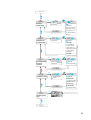
SET
DISPLY
Switching between the
standard displays
FREQ
Current standard display
NAME
/ :
FREQ, NAME,
CHAN
SET: Stores the setting
STORED
NAME
44
DISPLY
NAME
SET
Assigning the
transmitter a name
VOCAL
Current transmitter name
STORED
RESET
SET
RST. NO
Security check
Loading the factorypreset default settings
GUCAL
/ :
Transmitter name
(6 characters)
Letters w/o pronounciation
marks, numbers from 0...9,
special characters, spaces
SET: 5 x next character,
then store
RST. OK
/ : OK, NO
"reset" = OK:
SET: Transmitter loads
factory-preset default
settings (only pilot tone
setting is kept), transmitter
is restarted, standard
display appears
"reset" = NO
SET: Reset is cancelled
PILOT
SET
PLT. ON
Pilot tone transmission
activated or deactivated
Activating/deactivating
the pilot tone
transmission
PLT. OFF
/ : ON, OFF
SET: Stores the setting
STORED
SET
LOCK
OFF
LOC.OFF
Lock mode activated or
deactivated
Activating the lock mode
STORED
ON
LOC.ON
/ : ON, OFF
Lock mode = ON:
SET: Stores the setting
("STORED"), returns to
standard display
Lock mode = OFF:
SET: Stores the setting
SET
EXIT
Exiting the operating
menu
BANK
45
Adjustment tips for the operating menu
BANK
Switching between channel banks
Via the “BANK” menu, you can switch between the transmitter’s
nine channel banks. Each of the channel banks “1” to “8” has up to
20 switchable channels that are factory-preset to a transmission
frequency. The channel bank “U” (user bank) has up to 20
switchable channels to store your selection out of 1440
transmission frequencies that are freely selectable within the
preset frequency range.
When switching from one channel bank to another, the channel
with the lowest channel number is automatically displayed.
Note:
When using the transmitter with the tourguide system, the
channel bank “8” must be selected.
CHAN
Switching between the channels in a channel bank
Via the “CHAN” menu, you can switch between the different
channels in a channel bank.
TUNE
Selecting the frequencies to be stored in the channel
bank “U”
Via the “TUNE” menu, you can select the frequencies to be stored in
the channel bank “U” (user bank) .
When you have selected one of the channel banks “1” to “8” and
then select the “TUNE” menu, the transmitter automatically
switches to channel 01 of the channel bank “U”.
In this case, “U.01” briefly appears on the display.
Use the / buttons to select the desired transmission
frequency. Transmission frequencies are tunable in 25-kHz steps
within a switching bandwidth of 36 MHz max. For
intermodulation-free frequencies, please refer to the enclosed
frequency table.
SENSIT
Adjusting the sensitivity
Via the “SENSIT” menu, you can adjust the transmitter’s input
sensitivity.
46
The input sensitivity is adjusted too high when close talking
" distances, speakers with loud voices or loud music passages cause
overmodulation in the transmission link. When the audio input level
is excessively high (AF peak), the level display for audio signal
(AF) " shows full deflection.
If, on the other hand, the sensitivity is adjusted too low, the
transmission link will be undermodulated, which would result in a
signal with high background noise.
The sensitivity is correctly adjusted when the level display for audio
signal “AF” " shows full deflection only during the loudest
passages.
Note:
For monitoring the adjusted sensitivity, the transmitter’s level
display for audio signal “AF” always indicates the audio level –
even if the transmitter is muted.
The following figures are a guide to the best settings:
y Loud music/vocals: –30 to –20 dB
y Presentations:
y Interviews:
–20 to –10 dB
–10 to 0 dB
In order to be able to use highly sensitive directional condenser
microphones, the plug-on transmitter offers a sensitivity range extended
by 20 dB.
With the transmitter plugged onto a directional condenser microphone,
the following figures are a guide to the best settings:
y Loud music/vocals:
y Presentations:
y Interviews:
PHANTO
–50 to –40 dB
–40 to –30 dB
–30 to –20 dB
Switching the phantom powering on/off
(SKP 500 G2 only)
The plug-on transmitter can supply condenser microphones
without internal power supply with 48 V phantom powering (P 48).
The phantom powering can be switched on or off via the “PHANTO”
menu. Please note: Dynamic microphones can be operated in
phantom powering mode without harm. However, if no condenser
microphone module is being used, you should switch off the
phantom powering. With the phantom powering switched on, the
operating time of the batteries or the BA 2015 rechargeable battery
will be reduced.
47
DISPLY
Selecting the standard display
Via the “DISPLY” menu, you can select the standard display:
Selectable
standard display
Contents of standard
display
“FREQ“
“NAME“
“CHAN“
NAME
Entering a name
Via the “NAME” menu, you can enter a freely selectable name for
the transmitter. The name can be displayed on the standard display
and can consist of up to six characters such as:
y letters (without pronounciation marks),
y numbers from 0 to 9,
y special characters e.g. () - . _ and spaces.
To enter a name, proceed as follows:
After you have entered into the setting mode of the menu, the first
segment starts flashing on the display.
With the / buttons you can now select a character. By briefly
pressing a button, the display jumps either forwards or
backwards to the next character. If you hold down a button, the
display starts cycling continuously.
Press the SET button to change to the next segment and select
the next character.
Have you entered the name completely? Press the SET button to
store your setting and to return to the top menu level.
RESET
Loading the factory-preset default settings
Via the “RESET” menu, you can load the factory-preset default
settings. Only the selected setting for the pilot tone remains
unchanged. After the reset, the transmitter is restarted and the
standard display is shown on the display panel.
48
PILOT
Activating/deactivating the pilot tone transmission
(PILOT)
Via the “PILOT” menu, you can activate or deactivate the pilot tone
transmisssion.
When using the transmitter with the tourguide system, the pilot
tone transmission must be switched off.
LOCK
Activating/deactivating the lock mode
Via the “LOCK” menu, you can activate or deactivate the lock mode.
The lock mode prevents that the transmitters are accidentally
programmed or switched off during operation. The lock mode
icon ! on the display indicates that the lock mode is activated.
!
EXIT
To deactivate the lock mode, first press the SET button and then
press the / buttons to select “LOC.OFF”. If you confirm your
selection by pressing the SET button, the buttons can be operated
as usual.
Exiting the operating menu
Via the “EXIT” menu, you can exit the operating menu and return to
the standard display.
49
Troubleshooting
Error checklist
Problem
No operation
indication
No audio signal
RF signal available,
but no audio signal
Audio signal has a
high level of
background noise
Audio signal is
distorted
L 2015:
red LED flashes
besides a charging
compartment
Possible cause
Batteries are flat or
rechargeable battery is flat
Transmitter and receiver are not
on the same frequency.
The transmitter is out of range.
Possible solution
Replace the batteries or recharge the
accupack
Set transmitter and receiver to the
same frequency .
Reduce the distance between
transmitter and receiver.
The transmitter’s microphone is muted Deactivate the muting function
(“MUTE”)
Defective microphone
Replace microphone
Defective headphones
Replace headphones
Transmitter sensitivity is adjusted too see “Adjusting the sensitivity” on
low
page 46
Transmitter sensitivity is adjusted too
high
No contact with the rechargeable
battery (contacts are dirty or
rechargeable battery is not inserted
correctly)
rechargeable battery is defective
(overaged or defective rechargeable
battery cells)
rechargeable battery temperature is
too low or too high
Batteries (primary cells) or individual
rechargeable batteries have been
inserted
see “Adjusting the sensitivity” on
page 46
Clean the contacts or insert the
rechargeable battery correctly
Replace the accupack
Always charge the rechargeable
battery at room temperature
Only charge the BA 2015 accupack!
If still operating problems with your transmission installation occur, please contact your local
Sennheiser agent for assistance.
50
Recommendations and tips
... for the receiver EK 1038
y Transmission range depends to a large extent on location. There
should be a “free line of sight” between transmitting and
receiving antennas.
... for the radiomicrophones
y Hold the radiomicrophone in the middle of the microphone body.
Holding it close to the sound inlet basket will influence the microphone’s pick-up pattern, holding it at the lower part of the body
will reduce the transmitter’s range.
y You can vary the bass reproduction by increasing/decreasing the
talking distance to the microphone.
y For best results, make sure that the transmitter sensitivity is
correctly adjusted.
…for the bodypack transmitters
y Make sure that the antenna and the microphone cable do not
cross.
y The antenna should hang or stand freely and be at least 1 cm
away from the body. The antenna must not be in direct contact
with the skin.
y For best results, make sure that the transmitter sensitivity is
correctly adjusted.
51
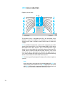
HDX noise reduction
Progress you can hear.
RF link
Inherent
noise
of the
RF link
Transmitter
Receiver
This product family is equipped with HDX, the Sennheiser noise
reduction system that reduces RF interference. It increases the
signal-to-noise ratio in wireless audio transmission to more than
110 dB.
HDX is a wideband compander system which compresses the audio
signal in the transmitter in a 2:1 ratio (related to dB) to lift it above
the inherent noise floor of the RF link. A 110 dB dynamic range
signal is thus transmitted with an effective dynamic range of only
55 dB, which is above the 60 dB noise floor of the RF link. In the
receiver the signal is expanded in an identical and opposite way in
a 1:2 ratio to restore the original signal, at the same time reducing
the RF noise to below the noise floor of the receiver.
HDX has been specially developed for high quality radiomicrophone
systems.
Note:
Only transmitters and receivers that are equipped with HDX can
work correctly with each other. If non HDX equipment was mixed
with HDX, the dynamic range would be drastically reduced and
the transmission would sound blunt and flat or shrill.
52
Accessories and spare parts
Only use original Sennheiser accessories and spare parts.
ATTENTION:
Components from other manufacturers (e.g. for power supply or
accupack) may cause damage to the units and will invalidate the
warranty!
The following accessories are available from your authorized dealer:
EK 1038 receiver
BA 2015 Accupack
L 2015 Charger for BA 2015 accupack
GP 03 Headphones (stereo jack plug)
EZT 1011 Induction loop
L 2015 quick charger
NT 1 Mains unit for powering
a singleL 2015 charger
NT 1-UK
with EU mains connector, 230 V
with UKmains connector, 230 V
NT 1-120
with USA mains connector, 110 V
NT 3 Mains unit for powering
threeL 2015 chargers
with EU mains connector, 230 V
NT 3-UK
with UK mains connector, 230 V
NT 3-120
with USA mains connector, 110 V
Transmitters of the evolution wireless series, G 2
SKM 100 G2 / SKM 300 G2 / SKM 500 G2 radiomicrophone
MD 835 Microphone head (green identification ring)
dynamic, cardioid
MD 845 Microphone head (blue identification ring)
dynamic, super-cardioid
ME 865 Microphone head (red identification ring),
condenser, super-cardioid
MMD 935 Microphone head (silver identification ring)
dynamic, cardioid
53
MZW 1 Wind- and popshield
MZQ 1 Microphone clamp
BA 2015 Accupack
L 2015 Charger for BA 2015 rechargeable battery
KEN 8 color-coded identification caps for radiomicrophone
SK 100 G2 / SK 300 G2 / SK 500 G2 bodypack transmitter
ME 2 Clip-on microphone,
condenser, omni-directional
MKE 2-ew Clip-on microphone , black or beige,
condenser, omni-directional
ME 4 Clip-on microphone,
condenser, cardioid
ME 3 Headmic,
condenser, super-cardioid
DC 2 DC power adapter, for external 12 V DC powering
(instead of two AA size batteries)
BA 2015 Accupack
L 2015 Charger for BA 2015 accupack
SKP 100 G2 / SKP 500 G2 plug-on transmitter
BA 2015 Accupack
L 2015 Charger for BA 2015 accupack
POP 1 Plug-on pouch
54
Specifications
Temperature range
-10°C to +55°C
EK 1038 receiver
Receiving frequencies
20
Frequency range
830–866 MHz (range E)
(channel assignment: see table below)
Switching bandwidth
36 MHz
Modulation
wideband FM
Nominal/peak deviation
± 24 kHz / ± 48 kHz
RF squelch
4 steps:
Adjacent channel rejection
> 70 dB
Noise reduction system
Sennheiser HDX
AF frequency response
40 – 15.000 Hz
Signal-to-noise ratio
> 91 dB(A)
THD at nominal deviation and 1 kHz
< 1 %, typ. 0.5 %
AF output (headphones)
3.5 mm stereo jack socket
AF output power
(peak deviation, 1 KHzNF ) PHONES
2 x ≥ 100 mW at 32 Ω
Min. terminating impedance of the
headphones
2x8Ω
Power supply
BA 2015 rechargeable battery with NiMH cells
SQ OFF
SQ LO: 5 dBµV
SQ MID: 15 dBµV
SQ HI: 25 dBµV
Operating timewith BA 2015 accupack approx. 6-10 hours depending on volume
with batteries
approx. 6-10 hours depending on volume
Dimensions
82 x 64 x 24 mm
Weight incl. accupack
approx. 185 g
55
L 2015charger
Input voltage:
10 - 20 V DC via hollow jack socket
Hollow jack:
Input current:
400 - 750 mA
Charging voltage:
2 x 2.9 V
Charging current:
2 x 700 mA
Charging principle:
∆U method
Deep discharge recovery charge
Trickle charge
rechargeable battery temperature monitoring
Over/undercharge detection
Charging time limit (max. 6 h)
Charging time:
approx. 2.5 h with a totally
discharged rechargeable battery and at room temperature,
automatic security switch-off after 6 h at the latest
BA 2015 battery type:
2 x 1.2 V 1500 mAh, NiMH
Dimensions:
approx. 145 x 80 x 110 mm
Weight:
approx. 310 g
Plug-in mains units
56
Plug-in mains unit for 1 charger
NT 1-EU (Cat. No. 09828), 230 V ±10 %, 1,8 A, 50 Hz
NT 1-UK (Cat. No. 04787), 230 V ±10 %, 1,9 A, 50 Hz
Plug-in mains unit for up to three
chargers
NT 3-EU (Cat. No. 04863), 230 V ±10 %, 1,8 A, 50 Hz
NT 3-UK (Cat. No. 04864), 230 V ±10 %, 1,9 A, 50 Hz
evolution wireless transmitters, G 2
Modulation
wideband FM
Frequency ranges
518–554, 626–662, 740–776, 786–822, 830–866 MHz
Transmission/receiving frequencies
8 channel banks with up to 20 factory-preset channels each
1 channel bank with up to 20 freely selectable channels
(1440 frequencies, tunable in steps of
25 kHz)
RF output power at 50 Ω
Power supply
typ. 30 mW
2 AA size batteries, 1.5 V
power consumption
at nominal voltage
≤170 mA
Operating time
> 8 h (SKP 500 G2 with P48 > 5 h)
SKM 100 G2 / SKM 300 G2 / SKM 500 G2 radiomicrophone
Dimensions
∅ 50 x 225 mm
Weight
approx. 450 g
SK 100 G2 / SK 300 G2 / SK 500 G2 bodypack transmitter
Max. input voltage
(at peak deviation)
MICRO: 1.8 Vrms (unbalanced)
LINE: 2.4 Vrms
Dimensions
82 x 64 x 24 mm
Weight
approx. 158 g
SKP 100 G2 / SKP 500 G2 plug-on transmitter
Max. input voltage
(at peak deviation)
Dimensions
MICRO: 1.2 Vrms (unbalanced)
Weight
approx. 195 g
105 x 43 x 43 mm
57
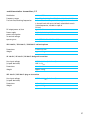
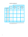
Channel assignment
evolution wireless G2, generation 2
EK 1038
SKM 100 G2
SK 100 G2
SKP 100 G2
SKM 300 G2
SK 300 G2
SKM 500 G2
SK 500 G2
SKP 500 G2
channel bank 8 channel bank 8 channel bank 8 channel bank 8
menu
menu
menu
menu
“TUNE“
“CHAN“
“CHAN“
“CHAN“
channel
range E
frequency
1
863,100
1
1
1
1
2
863,500
2
2
2
2
3
864,300
3
3
3
3
4
864,900
4
4
4
4
5
854,100
5
5
5
6
854,600
6
6
6
7
855,300
7
7
7
8
856,200
8
8
8
9
857,300
9
9
10
859,700
10
10
11
861,150
11
11
12
861,600
12
12
13
838,100
13
13
14
839,400
14
14
15
841,100
15
15
16
849,100
16
16
You must check whether or not the product needs to be licensed by
the national approval authorities.
58
59
EG-Konformitäts-Erklärung / EC Certificate of Conformity / Déclaration de conformité pour la CEE
Certificato di conformitá comunitario / Declaración de Conformidad / EG-Conformiteitsverklaring
SENNHEISER electronic GmbH & Co. KG
Am Labor 1, D-30900 Wedemark
erklären, dass die Produkte / declare that these devices / déclarons que ces appareils
declaramos que estos aparatos / dichiaria che questi apparecchi / verklaren, dat deze toestelen
SK 100/300/500 G2
Pocket Transmitter
SKM 100/300/500 G2
Transmitter, Hand-held
SKP 100/500 G2
Plug-On-Transmitter
den einschlägigen Anforderungen der EG-Richtlinie 89/336/EEC bzw.
der R&TTE-Direktive 1999/5/EC entsprechen.
Zur sachgemäßen Umsetzung der in den EG-Richtlinien genannten Anforderungen wurden
folgende Normen herangezogen:
conform to the basic requirements of EEC Directive 89/336/EEC resp. R&TTE Directive 1999/5/EC.
To effect correct application of the requirements stated in the EEC Directives,
the following standards were consulted:
sont conformes aux prescriptions fondamentales dans la Directive de la CEE 89/336/EEC or
la Directive R&TTE 1999/5/EC.
Pour mettre en pratique dans la règle de l’art les prescriptions des Directives de la CEE, il a été
tenu compte des normes suivantes:
complen los requimientos básicos de la normativa de la CEE 89/336/EEC resp. de la
normativa R&TTE 1999/5/EC.
Con il fin de realizar de forma adecuada los requirimientos referidos en las normativas de
la CEE fueron consaltadas las siguientes normativas:
sono conformi alla normativa 89/336/EEC resp. alla normativa R&TTE 1999/5/EC.
Per un’appropriato risconto nell’ambito della normativa CEE sono state consultate le seguenti normative:
evereenkomt met de basiseisen van de EG-Richtlijn 89/336/EEC resp. de EG-Richtlijn 1999/5/EC.
Om de eisen, die in de EG-Richtlijnen vermeld zijn, in juiste vorm om te zetten,
zijn van volgende normen gebruik gemaakt:
ETS 300 445
ETS 300 422
Wedemark, Oct, 2003
Klaus Willemsen
Key Projects
Product Marketing
Important:
Before putting the device into operation, please observe the respective country-specific regulations!
The guarantee period for this Sennheiser product is 24 months from the date of purchase. Excluded are
accessory items, rechargeable or disposable batteries that are delivered with the product; due to their characteristics these products have a shorter service life that is principally dependent on the individual frequency of use.
The guarantee period starts from the date of original purchase. For this reason, we recommend that the
sales receipt be retained as proof of purchase. Without this proof (which is checked by the responsible
Sennheiser service partner) you will not be reimbursed for any repairs that are carried out.
Depending on our choice, guarantee service comprises, free of charge, the removal of material and manufacturing defects through repair or replacement of either individual parts or the entire device. Inappropriate usage (e.g. operating faults, mechanical damages, incorrect operating voltage), wear and tear, force
majeure and defects which were known at the time of purchase are excluded from guarantee claims. The
guarantee is void if the product is manipulated by non-authorised persons or repair stations.
In the case of a claim under the terms of this guarantee, send the device, including accessories and sales
receipt, to the responsible service partner. To minimise the risk of transport damage, we recommend that
the original packaging is used. Your legal rights against the seller, resulting from the contract of sale, are
not affected by this guarantee.
The guarantee can be claimed in all countries outside the U.S. provided that no national law limits our
terms of guarant
Right of modifications reserved
Sennheiser electronic GmbH & Co. KG
30900 Wedemark, Germany
Phone +49 (5130) 600 0
Fax +49 (5130) 600 300
www.sennheiser.com
Printed in Germany
Publ. 04/05
512883/A01