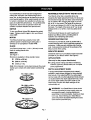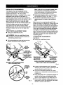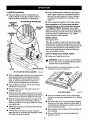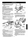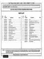
1
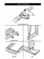
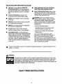
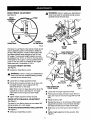
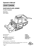
Owner's Manual
CRAFTSMAN®
DETAIL BISCUIT JOINER
Double Insulated
Model No.
315.175500
Save this manual for
future reference
CAUTION:
Read and follow all
Safety Rules and Operating
Instructions before first use of this
product.
Sears, Roebuck and Co., Hoffman Estates, IL 60179 USA
972000-415
10-00
NRTL
DETAIL
BISCUIT
JOINER
315.17S500
EDGE-TO-EDGE
JOINTS
BU'l'rJOINTS
MITER
JOINTS
T-JOINT
2
•
Typical Applications ........................................................................................................................................
2
•
Table Of Contents ..........................................................................................................................................
3
•
Warranty and Introduction ..............................................................................................................................
•
Rules For Safe Operation ..........................................................................................................................
•
Product Specifications, Unpacking, and Accessories ....................................................................................
3
4-6
7
•
Features .....................................................................................................................................................
•
Adjustments ............................................................................................................................................
t 0-11
•
Operation .................................................................................................................................................
12-17
•
Maintenance ...........................................................................................................................................
18-20
•
Troubleshooting ............................................................................................................................................
•
Exploded View and Repair Parts List .....................................................................................................
•
Parts Ordering / Service ...............................................................................................................................
FULL ONE YEAR WARRANTY
ON CRAFTSMAN
8-9
21
22-23
24
DETAIL BISCUIT JOINER
If this £11RF'I'$MRNBiscuit Joiner fails to give complete satisfaction within one year from the date of purchase,
RETURN IT TO THE NEAREST SEARS STORE IN THE UNITED STATES, and Sears will repair it, free of
charge.
If this CRRFT$14RNBiscuit Joiner is used for commercial or rental purposes, this warranty applies for only 90 days
from the date of purchase.
This warranty gives you specific legal rights, and you may also have other rights which vary from state to state.
Sears, Roebuck and Co., Dept. 817WA, Hoffman Estates, IL 60179
A
Your Biscuit Joiner has many features for making
cutting operations more pleasant and enjoyable.
Safety, performance and dependability have been
given top priority in the design of this Biscuit Joiner,
making it easy to maintain and operate.
Spline joinery is one of the strongest methods of
joinery used in woodworking. When glue is properly
applied to a spline and to the joint area of the wood
pieces being connected, a large surface area receives
the adhesion properties of the glue. This forms a very
strong joint.
CAUTION: Carefully read through this entire
owner's manual before u._g your new Biscuit
Joiner. Pay close attention to the Rules For
Safe Operation, Warnings and Cautions. If you
use your Biscuit Joiner properly and only for
what it is intended, you will enjoy years of safe,
reliable service.
Football shaped wafers, called biscuits, are then
placed inside the slots with glue and used to help line
up adjoining surfaces. When a water based glue is
used, the biscuits swell in the joint, making an extremely strong and firm bond. White glue, yellow glue,
carpenters glue, hide glue, and aliphatic resin glue are
examples of water based glues.
Traditional spline joinery requires cutting slots with a
router or table saw. Small, thin strips of wood must
then be cut to fit inside the slots and act as splines.
This bonding technique has traditionally been limited
to making edge-to-edge joints. However, with the use
of your new Biscuit Joiner, biscuits can now be easily
used to connect butt, miter, and T-joints. Biscuit
joining can be as strong as mortise and tenon, tongue
and groove, standard spline, and doweled joints. In
most cases the material around the biscuit will break
before the biscuit itself will break. A greater surface
area is exposed to glue in a biscuit joint, making the
seams stronger.
Newer methods of spline joinery use a plate or biscuit
joiner to cut precise mating oval slots in adjoining
boards. Your new Biscuit Joiner is a fast, simple, and
accurate plunge cutting tool that can be used for this
purpose. It can be used to cut slots in hardwood,
softwood, plywood, particle board, and other pressed
woods.
3
The purpose of safety symbols is to attract your attention to possible dangers. The safety symbols, and
the explanations with them, deserve your careful attention and understanding. The safety warnings do
not by themselves eliminate any danger. The instructions or warnings they give are not substitutes for
proper accident prevention measures.
SYMBOL
A
MEANING
SAFETY ALERT SYMBOL: Indicates caution or warning. May be used in conjunction with
other symbols or pictographs.
DANGER: Failure to obey a safety warning will result in serious injury to yourself or to others.
Always follow the safety p_ecautions to reduce the risk of fire, electric shock and personal injury.
\
\
WARNING: Failure to obey a safety warning can result in serious injury to yourself or to others.
Always follow the safety precautions to reduce the risk of fire, electric shock and personal injury.
A
NOTE:
DOUBLE
CAUTION: Failure to obey a safety warning may result in property damage or personal injury to
yourself or to others. Always follow the safety precautions to reduce the risk of fire, electric shock
and personal injury.
Advises you of information or instructions vital to the operation or maintenance of the equipment.
INSULATION
IMPORTANT
Double insulation is a concept in safety, in electric
power tools, which eliminates the need for the usual
three-wire grounded power cord. All exposed metal
parts are isolated from internal metal motor
components with protecting insulation. Double
insulated tools do not need to be grounded.
Servicing of a tool with double insulation requires
extreme care and knowledge of the system and
should be performed only by a qualified service
technician. For service we suggest you return the tool
to your nearest Sears Store for repair. Always use
original factory replacement parts when servicing.
_k
WARNING:
Do not attempt to operate this tool
until you have read thoroughly and understand
completely all instructions, safety rules, etc.
contained in this manual. Failure to comply can
result in accidents involving fire, electric shock, or
serious personal injury. Save owner's manual
•
and review frequently for continuing safe
operation, and instructing others who may use
this tool.
•
KEEP WORK AREA CLEAN. Cluttered areas
and benches invite accidents.
•
AVOID DANGEROUS
ENVIRONMENT.
Don't
use power tools in damp or wet locations or
expose to rain. Keep work area well lit.
KEEP CHILDREN AND VISITORS AWAY. All
visitors should wear safety glasses and be kept a
safe distance from work area. Do not let visitors
contact tool or extension cord.
READ ALL INSTRUCTIONS
STORE IDLE TOOLS. When not in use, tools
should be stored in a dry and high or locked-up
place - out of the reach of children.
KNOW YOUR POWER TOOL. Read owner's
manual carefully. Learn its applications and
limitations as well as the specific potential
hazards related to this tool.
DON'T FORCE TOOL. It will do the job better
and safer at the rate for which it was designed.
GUARD AGAINST ELECTRICAL SHOCK BY
PREVENTING BODY CONTACT WITH
USE RIGHT TOOL. Don't force small tool or
GROUNDED SURFACES. For example; pipes,
radiators, ranges, refrigerator enclosures.
attachment to do the job of a heavy duty tool.
Don't use tool for purpose not intended - for
example - A circular saw should never be used
for cutting tree limbs or logs.
KEEP GUARDS IN PLACE AND IN WORKING
ORDER.
4
RULES FOR SAFE OPERATION (Continued)
WEAR PROPER APPAREL. Do not wear loose
OUTDOOR USE EXTENSION CORDS. When
clothing or jewelry that can get caught in tool's
moving parts and cause personal injury. Rubber
gloves and nonskid footwear are recommended
when working outdoors. Wear protective hair
covering to contain long hair and keep it from
being drawn into nearby air vents.
tool is used outdoors, use only extension cords
suitable for use outdoors, Outdoor approved
cords are marked with the suffix W-A, for example - SJTW-A or SJOW-A.
ALWAYS WEAR SAFETY GLASSES. Everyday
eyeglasses have only impact-resistant lenses;
they are not safety glasses.
•
•
KEEP BLADES CLEAN AND SHARP. Sharp
blades minimize stalling and kickback.
•
KEEP HANDS AWAY FROM CUTTING AREA.
Keep hands away from blades. Do not reach
underneath work while blade is rotating. Do not
attempt to remove cut material when blade is
moving.
PROTECT YOUR LUNGS. Wear a face or dust
mask if the cutting operation is dusty.
•
PROTECT YOUR HEARING. Wear hearing
protection during extended periods of operation.
_k
WARNING:
Blades coast after turn-off.
•
NEVER USE IN AN EXPLOSIVE ATMO-
DON'T ABUSE CORD. Never carry tool by cord
or yank it to disconnect from receptacle. Keep
cord from heat, oil, and sharp edges.
SPHERE. Normal sparking of the motor could
ignite fumes.
SECURE WORK. Use clamps or a vise to hold
work. It's safer than using your hand and it frees
both hands to operate tool.
damaged, have repaired by authorized service
facility. Stay constantly aware of cord location
and keep it well away from the rotating blade.
INSPECT TOOL CORDS PERIODICALLY
•
DON'T OVERREACH. Keep proper footing and
balance at all times. Do not use on a ladder or
unstable support. Secure tools when working at
elevated positions.
KEEP HANDLES DRY, CLEAN, AND FREE
FROM OIL AND GREASE. Always use a clean
cloth when cleaning. Never use brake fluids,
gasoline, petroleum-based products, or any
strong solvents to clean your tool.
STAY ALERT AND EXERCISE CONTROL.
TOOLS. When not in use, before
Watch what you are doing and use common
sense. Do not operate tocd_whenyou are tired.
Do not rush.
servicing, or when changing attachments,
blades, bits, cutters, etc., all tools should be
disconnected from power supply.
REMOVE ADJUSTING
INSPECT EXTENSION CORDS PERIODICALLY and replace if damaged.
MAINTAIN TOOLS WITH CARE. Keep tools
sharp and clean for best and safest performance.
Follow instructions for lubricating and changing
accessories.
DISCONNECT
and if
CHECK DAMAGED PARTS. Before further use
KEYS AND
of the tool, a guard or other part that is damaged
should be carefully checked to determine that it
will operate properly and perform its intended
function. Check for alignment of moving parts,
binding of moving parts, breakage of parts,
mounting and any other conditions that may
affect its operation. A guard or other part that is
damaged should be properly repaired or raplaced by an authorized service center.
WRENCHES. Form habit of checking to see that
keys and adjusting wrenches are removed from
tool before turning it on.
AVOID ACCIDENTAL STARTING. Don't carry
plugged-in tool with finger on switch. Be sure
switch is off when plugging in.
MAKE SURE YOUR EXTENSION CORD IS IN
•
GOOD CONDITION. When using an extension
cord, be sure to use one heavy enough to carry
the current your product will draw. An undersized
cord will cause a drop in line voltage resulting in
toss of power and overheating. A wire gage size
(A.W.G.) of at least 16 is recommended for an
extension cord 100 feet or less in length. A cord
exceeding 100 feet is not recommended. If in
doubt, use the next heavier gage. The smaller
the gage number, the heavier the cord.
DO NOT USE TOOL IF SWITCH DOES NOT
TURN IT ON AND OFF. Have defective switches
replaced by an authorized service center.
GUARD AGAINST KICKBACK.
Kickback occurs
when the saw stalls rapidly and is driven back
towards the operator. Release switch immediately if blade binds or saw stalls.
5
RULES FOR SAFE OPERATION (Continued)
.
WHEN SERVICING USE ONLY IDENTICAL
CRAFTSMAN REPLACEMENT PARTS.
USE ONLY 1-1/2 In. (38 mm) DIAMETER
SPECIFIED BLADES. Do not use blades with
incorrect size holes, never us blade washers or
bolts that are defective, incorrect, or not specified.
SAVE THESE INSTRUCTIONS.
frequently and use them to instruct others who
may use this tool. If you loan someone this tool,
loan them these instructions also.
AVOID CUTTING NAILS, Inspect for and
remove all nails from lumber before cutting.
_WARNING:
Some dust created by power
sanding, sawing, grinding, drilling, and other
construction activities contains chemicals
known to cause cancer, birth defects or other
reproductive harm. Some examples of these
chemicals are:
NEVER touch the blade or other moving parts
during use.
NEVER start a tool when its moving component
is in contact with the workpiece.
NEVER lay a tool down before its moving parts
have come to a complete stop.
• lead from lead-based paints,
• crystalline silica from bricks and cement
and other masonry products, and
DO NOT operate this tool while under the
influence of drugs, alcohol, or any medication.
POLARIZED
• arsenic and chromium from chemicallytreated lumber.
PLUGS. To reduce the risk of
electric shock, this tool has a polarized plug (one
blade is wider than the other). This plug will fit in
a polarized outlet only one way. If the plug does
not fit fully in the outlet, reverse the plug. If it still
does not fit, contact a qualified electrician to
install the proper outlet. Do not change the plug
in any way.
_k
_i,
Look for this symbol to point out important
safety is involved.
Refer to them
Your risk from these exposures varies,
depending on how often you do this type of
work. To reduce your exposure to these
chemicals: work in a well ventilated area, and
work with approved safety equipment, such as
those dust masks that are specially designed to
filter out microscopic particles.
safety precautions.
It means
attention!!!
Your
WARNING:
The operation of any Biscuit Joiner can result in foreign objects being thrown into your eyes,
which can result in severe eye damage. Before beginning power tool operation, always wear
safety goggles or safety glasses with side shields and a full face shield when needed. We
recommend Wide Vision Safety Mask for use over eyeglasses or standard safety glasses with
side shields, available at Sears Retail Stores.
SAVE THESE INSTRUCTIONS
6
NoLoadSpeed
19,000RPM
Rating
120volts,60Hz,AC
Input
3.5Amperes
DepthOf Cut
WithMicroDepthOfCutAdjustment
0 - 9/32 in.
Your Biscuit Joiner has been shipped completely
assembled and ready for use. Inspect it carefully to
make sure no breakage or damage has occurred
during shipping. If any parts are damaged or missing,
contact your nearest Sears Retail Store to obtain
replacement parts before attempting to operate Biscuit
Joiner.
Fence Angles
Fence Height Adjustment
With Fence Angle Set On 90 °
With Fence Set On 45 °
Net Weight
R1 Biscuit Pack
7/32 in. x 5/8 in.
•
R2 Biscuit Pack
9/32 in. x 3/4 in.
•
R3 Biscuit Pack
1/2 in. x 1 in.
_
WARNING:
0 - 3/4 in.
5/16 in. - 13/16 in.
3.625 Ibs.
WARNING: If any parts are missing, do not
operate this tool until the missing parts are
replaced. Failure to do so could result in possible
serious personal injury.
The following recommended accessories are currently available at Sears Retail Stores.
•
45 ° and 90 °
The use of attachments or accessories not listed might be hazardous.
YourDetail
REVERSIBLE
Biscuit Joiner has been designed for
making fast, accurate, and simple plunge cuts in
wood, etc. so that biscuits can be used to join two or
more boards together. When used properly and only
for what it is intended, this versatile tool will give you
years of trouble-free performance. It is professionally
engineered, but its ease of operation allows the
amateur to produce beautiful and precise work.
FENCE
FOR 45 ° AND 90 ° CUTS
Your Biscuit Joiner has a reversible fence. By
loosening the height adjustment knobs, the fence can
be removed through key hole slots. Once removed, it
can be rotated 180 ° changing the angle of cut from
90 ° to 45 ° or vice versa. The height of the fence at
90 ° can be set between 0 to 3/4 in. from the center of
the blade. The height of the fence at 45 ° can be set
between 5/16 in. to 13/16 in. from the center of the
blade.
SWITCH
To turn your Biscuit Joiner ON, depress the switch
trigger. Release switch trigger to turn your Biscuit
Joiner OFF.
The fence should always be used to guide and
balance your Biscuit Joiner, providing ease of
operation and maintaining safe control.
MOTOR
NONSKID
Your Biscuit Joiner has a powerful motor with
sufficient power to handle tough cutting jobs. It
develops a no load speed of 19,000 RPM.
BACKING
PAD
The fence on your Biscuit Joiner is padded with a
nonskid backing pad to hold it stationary against the
workpiece. It helps prevent skidding when making
cuts. It also prevents marring of the workpiece from
Biscuit Joiner when cutting.
BLADE
Your Biscuit Joiner has a 1-1/2 in. (38 mm) 6 tooth
blade for cutting biscuit slots.
INDICATOR
BISCUITS
See Figure 1.
MARKS
Centerline and line of cut indicator marks have been
provided on your Biscuit Joiner. See Figure 2.
Biscuits are available in three standard sizes:
R1
(7/32 In. x 518 In.)
R2
(9/32 in. x 314 in.)
R3
(1/2 In. x I in.)
APPLICATIONS
(Use only for the purpose listed below)
•
Note: Store biscuits in a dry place because they swell
rapidly upon contact with water-based woodworking
glues.
Cutting precise mating oval slots in hardwood,
softwood, plywood, particle board, etc. for spline
joinery applications.
DEPTH ADJUSTMENT
KNOB
A spring loaded depth adjustment knob makes it
possible to make proper settiggs for three standard
size biscuits. Fine adjustments to the cutting depth
can be made with a knurled adjustment knob and jam
nut located behind the depth adjustment knob. Once
the correct depth setting has been made for one
biscuit size, the other two depth settings will be
automatically set.
R1 = 7/32 In. x 5/8 In.
R2 = 9/32 in. x 3/4 in.
_i
R3 = 1/2 In. x 1 in.
Fig. 1
8
WARNING:
Your Detail Biscuit Joiner should
never be connected to power supply when you
are assembling parts, making adjustments,
assembling or removing blades, cleaning or when
not in use. Disconnecting your Detail Biscuit
Joiner will prevent accidental starting that could
cause serious personal injury.
KNOW YOUR
See Figure 2.
DETAIL
BISCUIT
JOINER
_k
WARNING: Do not allow familiarity with tools to
make you careless. Remember that a careless
fraction of a second is sufficient to inflict severe
injury.
_
WARNING:
Do not attempt to modify this tool or
create accessories not recommended for use
with this tool. Any such alteration or modification
is misuse and could result in a hazardous
Before attempting to use any tool familiarize yourself
with all operating features and safety requirements,
ELECTRICAL
CONNECTION
Your Biscuit Joiner has a precision built electric motor.
It should be connected to a power supply that is 120
volts, 60 Hz, AC only (normal household current).
Do not operate this tool on direct current (DC). A
substantial voltage drop will cause a loss of power
and the motor will overheat. If your Biscuit Joiner does
not operate when plugged into an outlet, doublecheck the power supply.
condition leading to possible serious personal
injury.
LINEOF CUT
WINDOW
CENTERLINEI LINE
OFCUT INDICATOR
MARK(S)
REARHANDLE
IIDTH OF
CUTSCALE
DEPTH
ADJUSTMENT
KNOB
SWITCH
TRIGGER
KNU_ILED
ADJUSTMENT
KNOB
JAM
NUT
FENCE
HEIGHT
SETrlNG SCALE
REAR
BASE
FRONT
BASE
HEIGHT
ADJUSTMENT
KNOBS,)
NONSKID
BACKINGPAD
BOTfOM
SHOE
HEIGHT
INDICATORMARK
Fig. 2
DEPTH OF CUT ADJUSTMENTS
Note: Knob and jam nut are spring loaded, therefore pulling them in the direction of the arrow
shown puts pressure on the spring and releases
pressure from the depth adjustment knob.
Your Biscuit Joiner can be adjusted to three
standard cutting depths to accommodate three
standard size biscuits -- R1, R2, and R3.
Adjustments are made by engaging slots on depth
adjustment knob with tabs on rear base. For
example, when using a R1 size biscuit, rotate the
depth adjustment knob until the slot marked 1 aligns
with the depth indicator mark on the rear base.
When using a R2 size biscuit, rotate the depth
adjustment knob until the slot marked 2 aligns with
the depth indicator mark on the rear base, and
when using a R3 size biscuit rotate the depth
adjustment knob until the slot marked 3 aligns with
the depth indicator mark on the rear base. See
Figure 3.
TO SET DEPTH ADJUSTMENT
•
,_
•
•
Rotate depth adjustment knob until desired slot
setting aligns with tabs on rear base -- 1,2, or 3.
•
Next release knudedadjustmentknoband jam nut
applyingpressurefrom springon depthadjustment
knob.
Make a test cut in a scrap piece of wood. Fit the
correct size biscuit into biscuit slot. If biscuit slot is too
deep or too shallow, fine adjustments to the depth
setting can be made by loosening knuded adjustment
knob and making fine adjustments with the jam nut.
Turning jam nut forward will cut shallow biscuit slots.
Turning jam nut backwards will cut deeper biscuit
slots. The biscuit slot should be deep enough to allow
slightly more than one-half of the biscuit into the slot.
This extra room allows for proper alignment of the
wood being joined.
KNOB
Unplug your Detail Biscuit Joiner.
WARNING:
Failure to unplug Biscuit Joiner
could result in accidental starting causing possible serious personal injury.
TO MAKE
FINE ADJUSTMENTS
See Figure 4.
•
Pull knurled adjustment knob and jam nut in the
direction of the arrow shown in figure 3.
Unplug your Detail Biscuit Joiner.
\
DEPTH
INDICATOR
MARK
ROTATETO
DESIREDSETFING
1,2,0R3
PULLANDHOLDTO
ROTATEDEPTH
ADJUSTMENTKNOB
TURN FORWARD
FORSHALLOW
BISCUITSLOTS
REAR
BASE
TURNBACKWARDS
FORDEEPER
BISCUITSLOTS
KNURLEDADJUSTMENTKNOBUSEDAS A LOCKNUT.
JAM NUTUSEDTO MAKEFINEADJUSTMENTS.
RELEASETOAPPLY PRESSUREAGAINST
DEPTHADJUSTMENTKNOB
Fig. 4
KNURLED
ADJUSTMENT
KNOB
•
Loosen knurled adjustment knob. This knob is
used as a lock nut only. Loosen by twisting it in the
opposite direction away from jam nut.
•
Turn jam nut forward (clockwise) for a more
shallow cut, or backwards (counterclockwise) for
a deeper cut.
•
Once desired depth of cut is reached, hold jam nut
so that it will not move out of adjustment. Next,
tighten knurled adjustment knob against jam nut.
•
Recheck depth setting by making a test cut in a
scrap piece of wood. Also periodically check depth
setting for accuracy. See Figure 4.
JAM
NUT
DEPTH
ADJUSTMENT
KNOB
Fig. 3
10
FENCE
HEIGHT
ADJUSTMENT
_k
See Figure 5.
HEIGHT
ADJUSTMENT
KNOB(S)
WARNING:
Failure to unplug your Detail Biscuit
Joiner could result in accidental starting causing
possible serious personal injury.
ADJUSTMENt
KNOBS
TO
LOWERFENCE
(I) PULL
FORWARD
HEIGHT
SETrlNG SCALE
FRONT
BASE
_IP
Fig. 5
(2) SLIDE
DOWN
The fence on your Biscuit Joiner can be moved up and
down to adjust the position of the blade in relation to
the top of the workpiece. A scale on both sides of the
front base indicates height settings for both 45 ° and
90 ° angles. The fence and height indicator mark can
be positioned from 5/16 in. to 13/16 in. from the center
of the blade for 45 ° angles. It can be positioned from 0
to 3/4 in. from the center of the blade for 90 ° angles.
Scale marks are in increments of 1/16 in.
TO ADJUST
HEIGHT
FENCE
;"o'.'
_
HEIGHT
ADJUSTMENT
KNOBBOLT(S)
SETI'ING
See Figure 5.
•
_k
Unplug your Detail Biscuit Joiner,
SLOTS"
WARNING: Failure to unplug your Detail Biscuit
Joiner could result in accidental starting causing
possible serious personal injury.
•
Loosen the two height adjustment knobs.
•
Pull the fence forward and slide it up or down until
the height indicator mark is aligned with the
desired dimension on the scale.
KEY
HOLE SLOTS
FENCEORIENTATION
Note: Slots in the front base align with a tab on the
backside of the fence. See Figure 6. This alignment keeps the fence square at each height
setting,
•
ROTATION/ANGLE
ADJUSTMENT
See Figure 6.
Loosen the two height adjustment knobs.
•
Pull the fence forward and slide it down the front
base until it can be removed through the key hole
slots.
•
Rotate the fence 180 °.
•
Reinstall the fence on the front base. Place height
adjustment knob bolts in key hole slots and align
bolt heads with the slots on back of front base.
•
Slide fence up the front base to desired depth of
cut.
•
Tighten height adjustment knobs securely. See
Figure 6.
The fence on your Biscuit Joiner can be rotated 180 °
and set at either 45 ° or 90 ° angles.
TO ROTATE FENCFJCHANGE
See Figure 6.
•
ANGLE
SEI"rlNG
Unplug your Detail Biscuit Joiner.
11
Fig. 6
•
Tighten height adjustment knobs securely.
FENCE
SLOT(S)
FOR 90° ANGLES
FRONT
BASE
_h,
WARNING: Always wear safety goggles or
safety glasses with side shields when operating
tools. Failure to do so could result in objects
being thrown into your eyes, resulting in possible
serious injury.
•
Plug your Biscuit Joiner into power supply and
prepare to make your first cut. Grasp and hold your
Biscuit Joiner securely.
•
Place the fence against the board and align the
indicator marks on the fence with the centerline
mark(s) on the board. See Figure 7.
A variety of spline joints can be made using your
Biscuit Joiner. The number and size biscuits needed
INDICATOR
MARK(B)
for each joint depends on the thickness of the wood
and the length of the joint, in general, the small R1
biscuits should be used for miter cuts in small, thin
materials. The larger biscuits should be used for
edge-to-edge joinery.
When joining thick materials, stack two biscuits, one
above the other. For example, joining 2 in. x 4 in.
dressed lumber. See Figure 9. When joining even
thicker materials, use additional biscuits, stacked above
each other.
When making edge-to-edge joints the more biscuits
you use, the stronger the joint will be.
CENTERLINE
MARK(S)
The following sections illustrate how to make various
spline joints using your Biscuit Joiner.
EDGE-TO-EDGE
LINEOF CUTWINDOW
TOPVIEWOF DETAILBISCUITJOINER
JOINTS
Fig. 7
See Figures 7 and 8.
•
Edge-to-edge joinery is one of the most basic and
easiest joints to construct. In general, two basic
adjustments have to be made for all Biscuit Joinery
applications. One is the depth of cut and the other is
the location of the cut.
Depress the switch trigger and let the motor build
to its maximum speed, then gradually push Biscuit
Joiner forward to extend the blade into the wood.
•
When the base assembly bottoms out against the
depth of cut adjustment knob setting, pull back
releasing pressure on the spring. Blade will retract
from biscuit slot.
•
Repeat this procedure for all desired biscuit slots
and cutting the slots in the reating workpiece.
•
Once all biscuit slots have been cut, place a biscuit
in each joint and dry assemble the workpieces.
Make sure each joint lines up and fits.
•
Finally, disassemble the workpieces and place a
bead of glue in each slot. Also, spread a bead of
glue over the entire surface of the joint. Reinsert
the biscuits and assemble the workpieces. See
Figure 8.
HOW TO MAKE
EDGE-TO-EDGE
JOINTS
•
Unplug your Detail Biscuit Joiner.
•
Prepare the workpieces by laying them side by
side on a workbench in the order in which they will
be assembled.
•
Using a square, determine the location of each
biscuit spiine joint and mark the center of each joint
by drawing a line across each workpiece. Mark
edges 1 in. from the ends of workpieces. The joint
will be stronger if you use multiple biscuits placed
close together.
•
Set fence angle at 90 °.
•
Loosen height adjustment knobs, then pull and
slide the fence up or down until the indicator point
is aligned with the desired dimension on the scale.
Remember: The scale indicates the height of the
fence from the center of blade.
•
Tighten height adjustment knobs securely,
•
Select the correct depth of cut setting to match the
biscuit size you are planning to use. We suggest
that you make a test cut in a scrap piece of wood
from the same workpiece if possible.
•
Clamp workpiece securely so it will not move
during the cut.
CENTERLINEMARKS
"
_-J_J_
f
•
/
.
IT(S)
BISCUITSLOT(S)
EDGE-TO-EDGEJOINTS
Fig. B
Clamp workpieces together until the glue sets up.
BUTTJOINTS
•
Place the fence against the board and align the
indicator marks on the fence with the centedine
mark(s) on the board.
•
Depress the switch trigger and let the motor build
to its maximum speed, then gradually push Biscuit
Joiner forward to extend the blade into the wood.
•
When the base assembly bottoms out against the
depth of cut adjustment knob setting, pull back
releasing pressure on the spring. Blade will retract
from biscuit slot.
•
Repeat this procedure for cutting the slot in the
mating workpiece.
•
Once all biscuit slots have been cut, place a biscuit
in each joint and dry assemble the workpieces.
Make sure each joint lines up and fits.
•
Finally, disassemble the workpieces and place a
bead of glue in each slot. Also, spread a bead of
glue over the entire surface of the joint. Reinsert
the biscuits and assemble the workpieces. See
Figure 9.
•
Clamp workpieces together until the glue sets up.
See Figure 9.
A butt joint is one of the weakest joints in
woodworking. This type of joint is mating the end
grain of one board with the edge grain of another. The
bonding of glue on this type of surface is poor.
However, by using biscuits you can create a stronger
joint that gives a mortise-and-tenon effect.
BISCUIT
SLOT(S)
CENTERLINE
MARK(S)
OFFSET
See Figure 10.
MULTIPLE
BISCUITS STACKED
BUTr JOINTS
HOW TO MAKE
The rails of a table or workbench are often offset from
the front of the table legs. When offsets are required,
it is necessary to cut the slots in the rails first, then re-
Fig. 9
adjust the fence to cut the slots in the legs.
Keeping this one exception in mind, the procedure for
cutting offset butt joints is identical to the procedure
for cutting butt joints.
BUI-I" JOINTS
•
Unplug your Detail Biscuit Joiner.
•
Place the two pieces of wood to be joined on a
level workbench. Align them against each other in
the arrangement in which they will be assembled.
•
Using a square, determine the location of each
biscuit spline joint and mark the center of each joint
by drawing a line across the edges of the two
boards.
•
Set fence angle at 90 °.
•
Loosen height adjustment knobs, then pull and
slide the fence up or down until the indicator point
is aligned with the desired dimension on the scale.
Remember: The scale indicates the height of the
fence from the center of the blade.
BUTT JOINTS
For example -- If a 1/4 in. offset is desired, you would
mark the centerlines for cutting _'=buttjoint as
mentioned in the procedures for cutting butt joints,
and cut the slots in the ends of the rails. Next you
would raise the fence 1/4 in. to the desired offset and
cut the slots in the legs.
OFFSETBUTf JOINT
•
Tighten height adjustment
•
Select the correct depth of cut setting to match the
biscuit size you are planning to use. We suggest
that you make a test cut in a scrap piece of wood
from the same workpiece if possible.
•
Clamp workpiece securely so that it will not move
during the cut.
•
Plug your Biscuit Joiner into power supply and
prepare to make your first cut. Grasp and hold your
Biscuit Joiner securely with both hands.
BISCUITSLOT
BISCUIT
knobs securely.
CENTERLINE
MARK(S)
Fig. 10
13
H
m
•
T- JOINTS
Plug your Biscuit Joiner into power supply and cut
slots in all boards that require end slots. See Figure
13. Follow procedures explained in "Edge-ToEdge Joints". Rotate fence angle to 90 °, set fence
height at desired dimension on the scale, select the
correct depth of cut setting for the biscuit size you
plan to use, clamp workpiece securely, then cut
each slot at the marked centerline intersection.
See Figures 11-15.
A T-joint is used when the end of a board is joined to
the face of another board as shown in figure 11.
Attaching shelves to bookcases and inner support
braces to frames are typical applications. Actual
cutting of a T-joint is as simple as any other cut.
However, it is critical that you mark the centerlines,
mark the intersection points for each slot, and cut
each slot correctly. See Figure 11.
HORIZONTALBOARD
CENTERLINE
MARK(S)
_'_
BISCUIT(S)
BASE PLATE
CLEARANCE
SURFACE
CONTACT
TO CUTENDSLOTS IN
HORIZONTALBOARDS Fig. 13
CLAMP
BISCUITSLOT(S)
T- JOINTS
HOW TO MAKE
•
Fig. 11
T- JOINTS
TO REMOVE FENCE:
•
Unplug your Detail Biscuit Joiner.
•
Place the two pieces of wood to be joined on a
level workbench as shown in Figure 12. The inside
face of the vertical board should be facing up.
•
Unplug your Detail Biscuit Joiner.
•
Loosen height adjustment knobs, pull fence forward
and slide it down the front base until it can be
removed through the key hole slots. See Figure 14.
Next, select the correct depth of cut setting for the
biscuit size you plan to use, clamp workpiece
securely, and cut each slot at the marked centerline
intersection.
HORIZONTAL
BISCUITSLOT
BOARD
CENTERLINEMARK(S)
/
Next, you must remove the fence from your Biscuit
Joiner in order to cut slots into the face of the
vertical board.
SOARO
_.___RLINES
,_
WARNING:
When the fence is removed, the
cutter may be exposed. Use extreme caution to
avoid serious personal injury.
Fig. 12
•
Determine the location of each biscuit joint and
mark the centerlines on each board as shown. The
centerlines for both boards must line-up with each
other. Measure carefully, these measurements
must be accurate and precise. Tip: Measure twice
and cut once. In addition to the centedines lining
up, the spacing of the biscuit slots from side-to-side
must also match.
REMOVEFENCETO MAKEFACE
CUTSIN VERTICALBOARDS
14
Fig. 14
T-JOINTS (Continued)
•
•
Finally, disassemble the workpieces and place a
bead of glue in each slot. Also, spread a bead of
glue over the entire surface of the joint. Reinsert
the biscuits and assemble the workpieces. See
Figure 11.
•
Clamp workpieces together until the glue sets up.
Place your Biscuit Joiner on vertical board as
shown in Figure 15 and align indicator marks on
bottom shoe with centerline on vertical board.
CENTERLINE
MARK
ONWORKPIECE
BOTTOMSIDE OF BOTTOMSHOE
Upon completion of a T-joint cutting operation,
reinstall the fence on the front base by reversing
_'TO REMOVE FENCE" procedure. Place height
adjustment knob bolts in key hole slots and align bolt
heads with the slots on back of front base. Slide fence
up the front base to desired depth of cut, Tighten
height adjustment knobs securely.
INDICATOR
MARK
HORIZONTAL
BOARD
MITER
JOINTS
See Figures 16-16.
There are two types of miter joints that can be made
using biscuits: flat miters and edge miters. Flat miters
are used when making picture frames, Edge miters are
used when making boxes or things where you don't
want to show the end grain of the wood. Butt joints
show the end grain in wood,
HOW TO MAKE FLAT MITER
•
_
•
CLAMP
VERTICALBOARD
TO CUT SLOTSIN VERTICALBOARDS
Unplug your Detail Biscuit Joiner.
WARNING:
Failure to unplug your Detail Biscuit
Joiner could result in accidental starting causing
possible serious personal injury.
Place the pieces of wood to be joined on a level
workbench as shown in Figure 16.
Fig. 15
•
Place a straight piece of wood on the vertical board
and securely clamp it flush against the bottom
shoe. This piece of wood is used for a fence or
guide. It must be square with the sides of the
vertical board and parallel with the centerline.
•
Align centerline on bottom of shoe with marked
intersection for biscuit slot.
•
Plug your Biscuit Joiner into power supply and
prepare to cut slot.
•
Depress the switch trigger and let the motor build
to its maximum speed, then gradually push Biscuit
Joiner forward to extend the blade into the wood.
•
JOINTS
BISCUIT
FLATMITERJOINTS
When the base assembly bottoms out against the
depth of cut adjustment knob setting, pull back
releasing pressure on the spring. Blade will retract
from biscuit slot.
•
Repeat this procedure for cutting all required slots
in vertical boards.
•
Once all slots have been cut, place a biscuit in
each joint and dry assemble the workpieces. Make
sure each joint lines up and fits.
15
Fig. 16
•
Using a combination square, draw a line through
the center of each joint perpendicular to the mitered
edges.
•
Set fence angle at 90 °, set fence height at desired
dimension on the scale, select the correct depth of
cut setting for the biscuit size you plan to use, and
clamp workpiece securely.
•
Align indicator mark on fence with the centedine on
the workpiece.
•
Plug your Biscuit Joiner into power supply and
prepare to cut slot.
FLAT MITER JOINTS (Continued)
•
Depress the switch trigger and let the motor build
to its maximum speed, then gradually push Biscuit
Joiner forward to extend the blade into the wood.
•
When the base assembly bottoms out against the
depth of cut adjustment knob setting, pull back
releasing pressure on the spring. Blade will retract
from biscuit slot.
•
Repeat this procedure for cutting mating slot and all
required miter joint slots.
•
Once all slots have been cut, place a biscuit in
each joint and dry assemble the workpieces. Make
sure each joint lines up and fits.
•
Finally, disassemble the workpieces and place a
bead of glue in each slot. Also, spread a bead of
glue over the entire surface of the joint. Reinsert
the biscuits and assemble the workpieces. See
Figure 16.
•
Clamp workpieces together until the glue sets up.
HOW TO MAKE
EDGE
MITER
manPlace your Biscuit Joiner on workpiece with the
fence resting on the long side of workpiece as
shown in Figure 18. The front base should be
against the mitered edge of the workpiece.
CUTFINGEDGEMITERSLOT
FROMLONGSIDEOF WORKPIECE
Fig. 18
JOINTS
•
Unplug your Detail Biscuit Joiner.
•
•
Place the pieces of wood to be joined on a level
workbench as shown in Figure 17.
Recheck fence height setting to make sure it will
not cut through the workpiece.
•
Align indicator mark on fence with the centerline on
the workpiece. Make sure the front base is pressed
flat against the mitered edge of the workpiece.
•
Plug your Biscuit Joiner into power supply and
prepare to cut slot.
•
Depress the switch trigger and let the motor build
to its maximum speed, then gradually push Biscuit
Joiner forward to extend the blade into the wood.
•
When the base assembly I:_ttoms out against the
depth of cut adjustment knob setting, pull back
releasing pressure on the spring. Blade will retract
from biscuit slot.
I
Repeat this procedure for cutting mating slot and
all required miter joint slots.
•
Once all slots have been cut, place a biscuit in
each joint and dry assemble the workpieces. Make
sure each joint lines up and fits.
Fig. 17
•
•
Mark centerline of the joint on each board.
•
When making edge miter joints with workpieces
that have different thicknesses, clamp securely to a
workbench with the long sides up. This will assure
that the outside surfaces will match. See Figure 18.
Finally, disassemble workpieces and place a bead
of glue in each slot. Also, spread a bead of glue
over the entire surface of the joint. Reinsert the
biscuits and assemble workpieces. See Figure 17.
•
Clamp workpieces together until the glue sets up.
CENTERLINE
MARK(S)
BISCUIT
EDGEMITERJOINTS
•
Set fence angle at 45 °.
•
Slide the fence up or down until fence height is at
desired setting.
•
Tighten height adjustment knobs securely.
16
HINGE JOINTS
•
Determine the location of each hinge joint and mark
the center of each joint by drawing a line across
each workpiece.
•
Set fence angle at 90 °.
•
Loosen height adjustment knobs, then pull and
slide the fence down the scale until the height
indicator mark is set at zero depth of cut,
Remember: The scale indicates the height of the
fence from the center of the blade, which is
approximately .050 of an inch.
•
Tighten height adjustment knobs securely.
•
Select the #3 depth of cut setting. We suggest that
you make a test cut in a scrap piece of wood from
the same workpiece if possible.
•
Clamp workpiece securely so that it will not move
during the cut.
•
Plug your Biscuit Joiner into power supply and
prepare to make your first cut. Grasp and hold your
Biscuit Joiner securely with both hands.
•
Place the fence against the board and align the
indicator marks on the fence with the centerline
See Figure 19.
Hinge joints are used when joining two boards using
hinges supplied in one of Craftsman's optional hinge
kits. Jewelry boxes, doors on clocks, recipe boxes, etc,
are typical applications.
HINGE
SLOT(S)
HINGE
mark(s) on the board. See Figure 19.
•
Depress the switch trigger and let the motor build
to its maximum speed, then gradually push Biscuit
Joiner forward to extend the blade into the wood.
•
When the base assembly bottoms out against the
depth of cut adjustment knob setting, pull back
releasing pressure on the spring. Blade will retract
from hinge slot.
•
Repeat this procedure for all desired hinge slots.
•
Once all hinge slots have been cut, place a hinge
in each slot and dry assembl_ the workpieces.
Make sure each slot lines up and fits.
•
Finally, assemble the hinges to the workpiecas and
secure with the fasteners supplied.
FASTENERS
HINGE
Fig. 19
HOW TO MAKE
•
HINGE
JOINTS
Unplug your Detail Biscuit Joiner.
_
WARNING:
Failure to unplug your Detail Biscuit
Joiner could result in accidental starting causing
possible serious personal injury.
•
Prepare the workpieces to be joined by laying them
side by side on a workbench in the order in which
they will be hinged.
17
BLADE
REPLACEMENT
•
Using a 9/64 in.hex key, remove blade screw.
Note: Turn blade screw counterclockwise to
See Figures 20-22.
remove. See Figure 22.
After extended use, the blade on your Biscuit Joiner
may become dull. If you accidentally hit a nail or other
blunt object, it will dull or break the blade. These
situations require replacing the blade.
HOW TO REPLACE
•
,_
•
OUTER
BLADEWASHER
THE BLADE
I_)"_-"
BLADESCREW
GEAR
SPINDLEFLATS
BLADE
Unplug your Detail Biscuit Joiner.
BLADE
WARNING: Failure to unplug your Detail Biscuit
Joiner could result in accidental starting causing
possible serious pe_onal injury.
INNER
BLADE
WASHER
Place your Biscuit Joiner upside down on a
workbench and remove the bottom shoe screws
(4) and bottom shoe. See Figure 20.
SCREWS(4)
GEAR
SPINDLE
BOTTOM
Fig. 22
•
Remove outer blade washer and blade.
•
Clean wood particles and resin from blade washer
and all surrounding parts.
,_
Fig. 20
•
Place a #1 Phillips screwdriveror 3/16 in. diameter
pin between the blade and front base. See Figure 21.
•
Place one of the blade teeth against the
screwdriver or pin and lock blade preventing it from
rotating.
WARNING: If inner blade washer has been
removed, replace it before installing new blade.
Failure to do so could caus,=ean accident since
blade screw will not tightenproperly.
•
•
•
#1 PHILLIPSSCREWDRIVER
OR 3/11
Place inner blade washer on gear spindle. See
Figure 22.
Place new blade onto gear spindle and align flats
on blade with flats on gear spindle.
Secure with outer blade washer and blade screw.
•
Place a #1 Phillips screwdriver or 3/16 in. diameter
pin between the blade and front base. See Figure 21.
•
Place one of the blade teeth against the
screwdriver or pin and lock blade preventing it from
rotating.
BLADE
FRONTBASE
Note: Blade teeth point toward the right of your
Biscuit Joiner when held in normal operating
position. An arrow on the bottom shoe also
indicates direction of blade rotation. See Figure 20.
•
Fig. 21
18
•
Tighten blade screw securely.
Note: Turn blade screw clockwise to tighten.
Reassemble bottom shoe.
•
Replace screws (4) and tighten securely.
WARNING: When servicing, use only identical
Craftsman replacement parts. Use of any other
part may create a hazard or cause product
damage.
CLEANING
BASE ASSEMBLY
See Figures 23-25.
NOTCH(ES)
After extended use, wood particles and resin may
build up inside the base assembly of your Biscuit
Joiner and clog the path for wood particles going
through dust exhaust opening. Wood particles packing up in this area makes cutting biscuit slots more
difficult.
HOW TO CLEAN
•
REARBASE
TAB_)
BEARING
PLATE
BASE ASSEMBLY
Unplug your Detail Biscuit Joiner,
_1
WARNING: Failure to unplug your Detail Biscuit
Joiner could result in accidental starting causing
possible serious personal injury.
•
Place your Biscuit Joiner upside down on a workbench and remove the bottom shoe screws (4) and
bottom shoe.
•
Remove the blade, See "Blade
section.
•
•
SPRING(S)
Fig. 24
CAUTION: Blade tips are sharp. Be carefull not
to cut yourself when cleaning.
Clean wood particles and resin from slots and
surrounding areas on front and rear base. See
Figure 25. Apply a thin coat of general purpose
grease in slots or on bearing plate where base
slides.
Replacement"
ADJUSTMENT
ROD
With your Biscuit Joiner still upside down on a
workbench, remove front base screws (2). See
REAR
BASESLOT
FRONTBASE
REAR
BASESLOT
SCREWDRIVER
FRONT
BASESLOT
BASESLOT
Fig. 23
•
Fig. 25
Figure 23.
•
Pull front base in the direction shown by the arrow
in Figure 23 and remove.
Replace rear base. Position adjustment rod in its
proper place as shown in Figure 25.
•
Secure rear base in place with the two springs.
Hook one end of each spring in notch on each side
of rear base. Using needle nose pliers, stretch
each spring and hook it over tabs on bearing plate.
•
Using a pair of needle nose pliers, stretch and
release springs from tabs on bearing plate. See
Figure 24.
•
Lift adjustment rod away from bearing plate and
remove rear base.
•
Reassemble front base. Replace screws and
tighten securely.
•
With front and rear base assemblies removed,
place your Biscuit Joiner upside down on a
workbench and clean wood particles and resin
from bearing plate and surrounding areas. Note:
Also clean the blade, blade washers, etc.
•
Reinstall blade. Tighten blade screw securely.
•
Reassemble bottom shoe. Tighten screws (4)
securely.
19
GENERAL
_,
Only the parts shown on parts list, page 23, are
intended to be repaired or replaced by the customer.
All other parts represent an important part of the
double insulation system and should be serviced only
by a qualified Sears service technician.
WARNING: Always wear safety goggles or
safety glasses with side shields during power tool
operation or when blowing dust. If operation is
dusty, also wear a dust mask.
EXTENSION CORDS
The use of any extension cord will cause some loss of
power. To keep the loss to a minimum and to prevent
tool overheating, use an extension cord that is heavy
enough to carry the current the tool will draw.
Avoid using solvents when cleaning plastic parts.
Most plastics are susceptible to damage from various
types of commercial solvents and may be damaged
by their use. Use clean cloths to remove dirt, carbon
dust, etc.
A wire gage size (A.W.G.) of at least 16 is
recommended for an extension cord 100 feet or less
in length. When working outdoors, use an extension
cord that is suitable for outdoor use. The cord's jacket
will be marked WA.
_1_ WARNING: Do not _t any time let brake fluids,
gasoline, petroleum-based products, penetrating
oils, etc. come in contact with plastic parts. They
contain chemicals that can damage, weaken or
destroy plastic.
_b,
It has been found that electric tools are subject to
accelerated wear and possible premature failure when
they are used on fiberglass boats, sports cars,
wallboard, spackling compounds, or plaster. The
chips and grindings from these materials are highly
abrasive to electric tool parts such as bearings,
brushes, commutators, etc. Consequently, it is not
recommended that this tool be used for extended
work on any fiberglass material, wallboard, spackling
compounds, or plaster. During any use on these
materials it is extremely important that the tool is
cleaned frequently by blowing with an air jet.
CAUTION: Keep extension cords away from the
cutting area and position the cord so that it will
not get caught on lumber, tools, etc., during
cutting operation.
._1= WARNING:
Check extension cords before each
use. If damaged replace immediately. Never use
tool with a damaged cord since touching the
damaged area could cause electrical shock
resulting in serious injury.
Extension cords suitable for use with your Biscuit
Joiner are available at your nearest Sears Retail Store.
LUBRICATION
All of the bearings in this tool are lubricated with a
sufficient amount of high grade lubricant for the life of
the unit under normal operating conditions. Therefore,
no further lubrication is required.
HELPFUL
J'
HINTS
Always clamp workpiece securely before cutting.
J
Study all safety rules and do the job safely.
A safe operator is one who thinks ahead.
,+/
Never place your hands in jeopardy.
,f
Always wear eye protection when cutting slots.
•f
Make certain clamps can't loosen while in use.
J
Make set-up adjustments carefully. Then double
check. Measure twice and cut once.
J'
Test difficult set-ups on scrap---Don't waste
lumber.
J"
Always dry assemble your project before gluing
it together.
,/
Plan each operation before you begin.
J'
J'
For loose fit situations, wet biscuits to make
them swell.
J
The more biscuits used, the stronger the joint
will be.
Provide for smoother operation by cleaning your
Biscuit Joiner frequently. Shake Biscuit Joiner or
blow with an air jet to remove wood particle
build-up.
4
Keep blade clean. When the blade becomes
dull, replace it.
Do not abuse power tools. Abusive practices
can damage tool as well as workpiece.
J
Think safety by thinking ahead.
J"
J
Don't let familiarity make you careless.
20
PROBLEM
Biscuits do not fit slots. Biscuits not fitting
slots may also cause misalignment of
boards being joined.
1,
Wood particles begin to backup on front of
unit.
2.
.
,
Blade becomes difficult to push in when
cutting slots. Blade does not retract
properly when cutting slots.
Cutting performance is poor and there is a
loss of power or stalling of motor when
cutting slots.
SOLUTION
A.
Biscuit slots are too deep or too shallow. Make
fine adjustments to depth setting. See "TO
MAKE FINE ADJUSTMENTS" section on page
10.
B.
Biscuit thickness may be out of tolerance.
Compress biscuits in a vise if they are too thick,
C.
Check to see if biscuits are the correct size for
the size slots that have been cut: #1, #2, or #3.
D.
Check to see if biscuits have gotten wet and
swollen.
E.
If biscuits fit loose in slots, wet them to take up
the loose fit.
A.
Dust exhaust may be clogged preventing wood
particles from going through dust exhaust
opening. Remove bottom shoe and clean blade,
bearing plate, base assembly slots, and
surrounding areas. See "CLEANING BASE
ASSEMBLY" section on page 19.
A.
Wood particles and resin have built up on base
assembly slots and surrounding areas. Remove
front and rear base assemblies and clean blade,
bearing plate, base assembly slots and
surrounding areas. Apply a thin coat of general
purpose grease in slots or on bearing plate where
base slides. See "CLEANING BASE
ASSEMBLY" section on page 19.
A.
Blade is dull. Replace blade. See "BLADE
REPLACEMENT" section on page 18.
B.
Resin has built up on blade. Remove blade and
clean it with gum and pitch remover. See
"BLADE REPLACEMENT" section on page 18
for blade removing instructions, Once clean,
follow "BLADE REPLACEMENT" instructions to
replace the blade,
21
J
CRAFTSMAN
DETAIL BISCUIT JOINER - MODEL NUMBER 315.175500
SEE NOTE "A" PAGE 23
24
25
23
12
13
14
I
22
J
15
21
11
CRAFTSMAN
DETAIL BISCUIT JOINER - MODEL NUMBER
315.175500
I The
model
numberJOINER
will be found
on aordedng
plate attached
to the motor housing. Always mention the model number in all correspondence regarding your
DETAIL
BISCUIT
or when
repair parts.
SEE BACK PAGE FOR PARTS ORDERING
I
INSTRUCTIONS
PARTS LIST
Key
No.
Part
Number
1
975787-001
Data Plate .......................................................
1
15
974212-001
Shoe ...............................................................
2
975788-001
Logo Plate ......................................................
1
16
622210-040
Screw (#8-32 x 1/2 in. Flat Hd. T.C.) .............. 4
2
17
612284-002
Blade Screw (#8-32 x 3/8 in. Soc. Cap) ......... 1
974209-001
Outer Blade Washer .......................................
1
3
663711-001
Description
Key
No.
Quan.
Tension Spdng ...............................................
Part
Number
Description
Quan.
1
4
931055-806
Washer ...........................................................
2
18
5
975193-001
Gear Assembly ...............................................
1
19
975796-001
Blade ..............................................................
1
6
974204-002
Bearing Plate With Bearing ............................ 1
20
974199-001
Inner Blade Washer ........................................
1
7
623275-003
* Screw (#10-24 x 3/4 in. Fil. Hd.) ..................... 2
21
974217-001
Front Base Pad ...............................................
1
8
974219-002
1
22
974220-001
Height Adjustment Knob .................................
2
9
703477-006
1
23
974221-001
Adjustable Fence ............................................
1
10
971498-001
Knurled Adjustment Knob ...............................
1
24
974210-002
Front Base ......................................................
1
11
974211-001
Rear Base .......................................................
1
25
623166-002
Bolt (1/4-20 x 3/4 in. Sq. Hd.) ......................... 2
12
663703-001
Compression Spring .......................................
1
26
974208-001
Ball Beadng (NMB R-1560X2ZZR) ................. 1
13
974218-001
Adjustment Rod ..............................................
1
27
975275-001
Gear ................................................................
14
622183-042
* Screw (#8-32 x 3/8 in. FiL Hd.) ....................... 4
28
975797-001
Optional Carbide Tipped Blade (Not Shown). 1
972000-415
Owner's Manual
Depth Adjustment Knob ..................................
* Jam Nut (#8-32) ..............................................
NOTE: "A "- The assembly shown represents an important part of the Double Insulated System. To avoid the possibility of alteration or damage
to the system, service should be performed by your nearest Sears Repair Center. Contact your nearest Sears Retail Store for
Service Center information.
* Standard Hardware Item -- May Be Purchased Locally
.,.
23
1
For repair of major brand appliances in your own home...
no matter who made it, no matter who sold it!
1-800-4-MY-HOME
sMAnytime,
day or night
(1-800469-4663)
www.sears.com
To bring in products such as vacuums, lawn equipment and electronics
for repair, call for the location of your nearest Sears Parts & Repair Center
1-800-488-1222
Anytime, day or night
www.sears.com
For the replacement parts, accessories and owner's manuals
that you need to do-it-yourself, call Sears PartsDirect sM!
1-800-366-PART
(1-800-366-7278)
6 a.m. - 11 p.m. CST,
7 days a week
www.sears.com/partsdlrect
To purchase or inquire about a Sears Service Agreement:
1-800-827-6655
7 a.rn. - 5 p.m. CST, Mon. - Sat.
Para pedir servicio de reparacibn a domicilio,
y para ordenar piezas con entrega a domicilio:
1-888-SU-HOGAR
su
Au Canada
pour service en fran(;ais:
1-877-LE-FOYER _
(1-877-533-6937)
(1-888-784-6427)
HomeCentrar
® Registered Trademark / _
Q Sears, Roebuck and Co.
® Mama Registrada /
TM
Trademark of Sears, Roebuck and Co.
Mama de Fdbdca de Sears, Roebuck and Co.