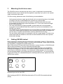
1
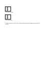
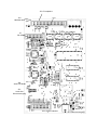
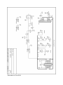
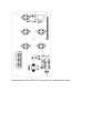
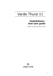
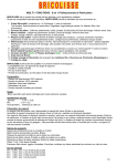
OSCAR
MP3-Player
Kit instructions
Version B, November 2000
BayCom
Important Note:
Ideas, texts, figures and circuits in this manual and design, hard- and software of the OSCAR MP-3
player are copyright protected. Distribution, in whole or parts of it, publication and manufacturing of
copies of the OSCAR MP-3 player or the copying or modifying of the manual is prohibted. Licences may
be obtained from the copyright holders.
All copyrights are held by Alexander Kurpiers, Vladimir Pantelic and Johannes Kneip.
Copying and distributing music is also liable to copyrights of third parties in most cases. As a user of
OSCAR, you must obey to these copyrights. The OSCAR manufacturers can not be held liable for
copyright violations caused by OSCAR users.
Copyright holders address:
BayCom Ingenieurbüro
Bergstr. 15
01465 Liegau-Augustusbad
GERMANY
PCB Version: 10/00
1
Overview
The kit allows the construction of OSCAR, a CD-ROM or hard disk based MP3 player. The kit consits
of the following components:
1.
2.
3.
4.
5.
Main PCB (PCB = printed circuit board), 100* 160mm
Front PCB, with switches and rotary encoder, cable for connection to main board
LCD-Display, four lines, 20 digits
Flat cable for the connection between display and front PCB
This manual and OSCAR manual
Not part of the kit, but necessary for operation are the following components:
-
2
ATAPI-CD-ROM drive. Toshiba brand (e.g. XM6402B, XM6502B) is recommended
Power supply 12V 2A, 5V 2A, stabilized
AT-Bus-Cable 40p
Audio-Cable from CD ROM to main board, 4p, shielded (standard computer audio cable)
Cable for headphone and amplifier connection
Assembly
As the first steps, the connections between display, front PCB and main PCB are established. Then,
the main PCB is connected to the CD ROM drive and the power supply.
2.1
Connection Display – Front PCB
The display is connected to the front PCB via two 6 p. cables as shown on the drawing. This connects
the LCD data bus, but also the power supply for the LED background lighting.
Use the flat cable in the kit for soldering the connection. The four pins in the middle of the connector
need not be connected. Please keep the connection as short as possible, to avoid interferences the
cable should not exceed 30-40cms in length.
IRSen
sor
Display
Front PCB
Connector to main PCB
2.2
Front PCB
The front PCB carries five keys and a rotary encoder. With the help of a variable resistor the contrast
of the display can be adjusted. An Infrared Sensor (SFH 536) can be assembled additionally. A
suitable remote control is available via BayCom. See OSCAR user manual for a detailed description of
the key functions. A circuit diagram of the front PCB is shown on one of the following pages, if you
should intend to modify layout or design of the front PCB. The circuitry around the 74HCT86 is
required for the IR sensor only and is not necessary, when the IR sensor is not assembled.
2.3
Connecting the Main PCB
An assembly plan of the main PCB is shown on one of the next pages. It shows the position of the
connectors on the OSCAR main board. Pin 1 is marked for all connectors. The following diagram
shows the principal layout of the other connector pins:
Pin2
4
...
Pin 1
3
5
7
Pins and their numbers on the OSCAR connectors
Establish the following connections:
Front PCB to Main PCB
The connection is established via the 20p. flat cable directly mounted to the front PCB. The connector
has to be connected in a way that Pin 1 of the cable (red marking) fits onto Pin 1 of JP3 on the main
PCB.
CD-ROM to main PCB
Connection is established via a standard 40 pin AT bus flat cable (PC accessorie). Pin 1 (red marking)
on the main PCB (JP5) has to be connected to Pin 1 of the CD ROM drive.
Additionally, the CD ROM Nf has to be connected to the main PCB, since this is used to play normal
audio CDs. Connect a standard CD ROM Audio cable from the CD-ROM connector to JP9 on the
main PCB. Please check the polarity, otherwise L/R audio channels may be reversed.
RS-232 to main PCB
The RS-232 is used to monitor the OSCAR operation on a PC (detailed description in th OSCAR user
manual). JP2 connects directly to a sub-D 9p. adapter as it is used on most serial PC cards.
Necessary connections are:
Pin 2 OSCAR connects to Pin 2 RS232
Pin 3 OSCAR to Pin 3 RS232
Pin 5 OSCAR to Pin 5 RS232
Other pins are not used. Please not the differing numbering of the pins of this connector (see
connector layout on next page)
JP4 can be used to connect a hard disk activity LED.
Audio-Outputs.
All audio outputs can be found on JP7. The headphone outputs should be connected to a normal
3.5mm or 6.3mm head phone connector, the line-out outputs should be connected to Cynch
connectors. A shielded cable is recommended. The output level of the line outputs is 150mV at
47kOhm, for the headphones it is 500mV at 390 Ohms.
The remaining pins of JP7 can be used for power supply of the main PCB.
Power supply
OSCAR requires 400mA at 5V and 100mA at 12V. Both supply voltages have to be properly
stabilized. Please not that power for CD ROM and hard disk are an additional load for the power
supply. We recommend a power supply which is capable to deliver 5V 2A and 12 2A simultaneously.
A direct connection to the power supply of a car battery is prohibited, since the voltage may vary
significantly. Also here a proper stabilization to 5 and 12V is required.
The power supply can be connected either via JP1 or the remaining pins of JP7, see connector layout
below.
Please not: The PCB does not have a protection against wrong polarity or over voltage. Wrong polarity
or overvoltage will result in a fatal damage to the main PCB and the display.
Connector Layout:
Pin
1
2
3
4
5
Function
Nc
RxD
TxD
Nc
GND
Pin
1a
2a
3a
4a
5a
Function
Nc
Nc
Nc
Nc
nc
JP2: RS232 (Please not different pin numbering!)
Pin
20
18
16
14
12
10
8
6
4
2
Function
GND
KEY1
KEY3
KEY5
KEY7
LCD_D5
LCD_E
LCD_RS
Pin
19
17
15
13
11
9
7
5
3
1
Function
VCC
KEY0
KEY2
KEY4
KEY6
LCD_D6
LCD_D4
LCD_R/-W
IR_IRQ2
JP3: Front PCB/LCD-Interface
Pin
1
3
5
7
9
11
13
15
17
19
Function
+5V
+5V
+12V
GND
GND
GND
GND
GND
GND
GND
Pin
2
4
6
8
10
12
14
16
18
20
Function
+5V
+5V
+12V
GND
GND
GND
Kopfhörer L
Kopfhörer R
Line Out L
Line Out R
JP7: Audio Out / Power supply
Pin
1
2
Function
LED A
LED K
JP4: HD activity
Pin
1
2
3
4
Function
A_in R
GND
GND
A_in L
JP9: Audio-CD ROM
Pin
1
2
3
4
Function
+12V
GND
GND
+5V
JP5: Power Supply
All other connectors on the PCB are used for internal purposes or diagnosis and should not
be used.
JP3: Frontplatine
JP4
Harddisk-Aktiv
Pin1
Pin1
Pin1a
JP
RS-232
Pin1a
JP9:
Audio-CD-ROM
Pin1
JP7:
Audio Out
Stromversorgung
Pin1
Pin1
JP5: ATAPI-Interface
JP1: Stromversorgung
Schematics of Front PCB
Assembly plan for front PCB. The IR sensor is not assembled for the kit.
3
Mounting the kit into a case
The OSCAR kit can be mounted into any rack or case. A metal case is recommended.
Please be aware of your national security regulations, especially if you plan to use a power
supply connected to the mains.
For the mounting, please take care of the following recommendations:
-
4
Audio ground and power supply ground should not be connected anywhere. An isolated
mounting of the line out and head phone connectors is recommended
All AF lines should be kept as short as possible. A shielded cable shoud be used.
All flat cables should be kept as short as possible, 30 - 40 cm is the maximum length
which is recommended.
The case should be as HF tight as possible, a good metal rack is recommended.
If you plan to use an additional hard disk, please look up the recommendations in the
OSCAR user manual.
The trimmer for the contrast adjustment on the front PCB is accessible thhrough a whole
in the PCB. Please make sure that you cann access this trimmer after mounting the kit
into the case (or regulate contrast before mounting OSCAR into the case)
The axis of the rotary encoder is connected to one of it’s output signals. The knob to be
used should either be isolated or should be mounted isolated from the axis to prevent
electrostatic damage.
Getting OSCAR started
Before powering up, please check all connections as described in section 2. Especially the
correct connection of the power supply is crucial to prevent damage. Please make sure that
the CD-ROM is connected to the power supply, too.
Main PCB and front PCB have been factory checked on proper function, so OSCAR should
start up without problems if you have connected everything right.
Before powering up, turn the knob for LCD to the left. After powering up, the initialisation
message should appear on the LCD display and the display should be illuminated. If you
cannot see the initialisation message, try to adjust the contrast trimmer over ist full range.
See the following diagram for the keyboard layout. By pressing EJECT, you should be able
to open the CD tray. For a detailed description of the keyboard functions, please refer to the
OSCAR user manual.
EJECT
MENU
IRSen
sor
HOTKEY
STOP
UP
Keyboard layout on the front PBC
After inserting an MP3 CD, OSCAR should scan the CD for .MP3 files and should start
playing.
5
Troubleshooting
From our experience, most problems with the kit can be found by doublechecking the wiring
and a close examination of all connections and wirings.
As a first step, we would ask you to
-
doublecheck ALL wirings
Checking the power supply (please measure the voltage). Are there really +5.0V and
+12.0V on the PCB (maximum tolerance 5%).
Here is a list of known problems and their origins:
No display information, but keyboard works and CD is scanned.
- Wrong adjustment of contrast
- Data lines to display are connected the wrong way or short circuit between wires.
CD-ROM or hard disk is not found, display information is present.
- AT bus not connected properly, connector is turned 180 degrees
- CD ROM must be jumpered AT bus master, hard disk (if available) in slave mode
Audio-channels: Right and left channel reversed for audio CDs, correct for MP3:
- Turn connector on JP4 for 180 degrees
- Wrong connection on AF cable
Level on Head phones too low
- Head phones connected to line out
- Adjust level via OSCAR menue
CD-ROM drive operates with high rpm the whole time, lot of noise
- This problem is known from some drives, which do not allow proper speed adjustment via
the AT bus (e.g. TEAC). We recommend the use of actual Toshiba drives, which are also
used for the assembled OSCAR versions. They have proved to be highly reliable.
If you should continue to have problems to get OSCAR started or need other assistance,
please contact us at [email protected].
BayCom
Service informations
Ordering OSCAR or parts
All BayCom articles can be ordered via the address provided below. Please ask for actual
pricing informations.
Order information:
1500
1510
OSCAR-MP3 Player, assembled, incl. remote control
OSCAR-MP3 Player, main and front PCB (do-it-yourself-kit)
Technical Hotline, Warranty and Repairs:
You have a warranty on the function of the kit according to the actual german warranty
regulations. There is no warranty for damages caused by:
- Wrong handling,
- Static damage,
- Overvoltage
- Short circuits
- Modifications to the boards.
We provide support mainly by e-mail. Our telephone number is ++49 3528 414277. BayCom
is a part time business, so we recommend to contact us during the eveing hours (7-11 p.m
GMT). FAX number is ++49 3528 414278 (24h)
Please contact us before sending back any equipment for service or repair.
Aktuelle Informations on OSCAR and softwareupdates can be found at
www.oscar-mp3.de (deutsch)
www.oscar-mp3.com (englisch)
BayCom Ingenieurbüro
Bergstr. 15
01465 Liegau-Augustusbad
Deutschland
Tel. 03528 414277
FAX 03528 414278
[email protected]