1
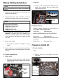
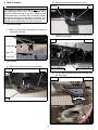
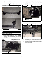
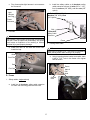
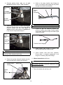
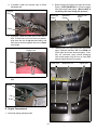
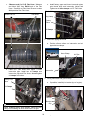
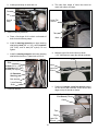
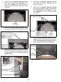
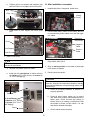
3651 N. Hwy. 89 • Chino Valley, AZ 86323
(928) 636-7080
2011-2013
2011-2014
CHEVY/GMC
WARNING
2500HD/3500HD
DURAMAX DIESEL PICKUP
(New Body Style)
3” BODY LIFT
INSTALLATION INSTRUCTIONS
KIT
#10253
This kit should only be installed on a vehicle that is in
good working condition. Before you install the kit, thoroughly inspect the vehicle for corrosion or deformation
of the sheet metal around the factory body mounts. If
the vehicle is suspected to have been in a collision or
misused, do not install this kit. Off-road use of your
vehicle with this kit installed may increase the stress
applied to the factory body mounts. We do not recommend that any vehicle with a body lift kit installed be
involved in any extreme off-road maneuvers such as
jumping. Failure to observe this warning may result in
serious personal injury and/or severe damage to your
vehicle.
WARNING
WARNING
Installation of a Performance Automotive Group body
lift kit will change the vehicle’s center of gravity and
handling characteristics both on and off-road. You must
drive the vehicle safely! Extreme care must be taken to
prevent vehicle rollover or loss of control, which could
result in serious injury or death. Avoid sudden sharp
turns or abrupt maneuvers and always make sure all
vehicle occupants have their seat belts fastened.
Many states and municipalities have laws restricting
bumper heights and vehicle lifts. Consult state and
local laws to determine if the changes you intend to
make to the vehicle comply with the law.
WARNING
The installation of larger tires may reduce the effectiveness of the Braking System.
WARNING
Before you install this kit, read and understand all
instructions, warnings, cautions, and notes in this
instruction sheet and in the vehicle owner’s manual.
WARNING
Always wear eye protection when operating power
tools.
CAUTION
WARNING
Proper installation of this kit requires knowledge of the
factory recommended procedures for removal and
installation of original equipment components. We recommend that the factory shop manual and any special
tools needed to service your vehicle be on hand during
the installation. Installation of this kit without proper
knowledge of the factory recommended procedures
may affect the performance of these components and
the safety of the vehicle. We strongly recommend that
a certified mechanic familiar with the installation of similar components install this kit.
Before you install this kit, block the vehicle tires to prevent the vehicle from rolling.
WARNING
Accidental deployment of the air bag can result in serious personal injury or death. To avoid accidental
deployment during installation of the kit, the Supplemental Restraint System (SRS, or airbag) must remain
deactivated. Do not allow anyone near the airbag during installation. Refer to the factory service manual or
owner's manual for the recommended procedure to
disable the SRS. After you install the kit, reactivate the
SRS before driving the vehicle.
WARNING
DO NOT combine suspension, body, or other lift
devices. Use of vehicle with combined lifts may result
in unsafe and/or unexpected handling characteristics.
NOTE
Performance Automotive Group recommends using
the Loctite® supplied in the kit on the threads of all kit
nuts and bolts unless specified otherwise in these
instructions.
1
2011 Chevy / GM 2500 & 3500 Diesel-Kits 10253
Before Starting Installation
2. Airbag fuse
a. Remove cover and airbag fuse “SIR” from fuse
panel. Fuse locations may vary. Check fuse
chart on back of cover.
NOTE
Kit parts are prefaced by the word kit and appear in
bold print.
1. Carefully read all warnings and instructions completely before beginning.
2. Verify all parts have been received in this kit by
checking the parts list at the end of this document.
Airbag
Fuses
NOTE
If parts are missing from kit, please be prepared to provide the following information:
1. Name of purchase location
2. Bar Code on side of box
3. Date above bar code
4. Date inside box cover
5. Inspector # from inside box cover
B. Measurements
1. Measure distance between the front bumper and
front fenders. Record measurement.
Driver Side _____
3. Only install this kit on the vehicle for which it is
specified. If anytime during the installation you
encounter something different from what is outlined
in the instructions, call technical support at (928)
636-7080.
Passenger Side _____
2. Measure distance between rear bumper and bed.
Driver Side _____
Passenger Side _____
3. Measure and record distance between cab and bed
both sides.
4. Special tools needed:
Driver Side _____
a. Die grinder or similar tool capable of cutting
metal.
Passenger Side _____
Prepare to install kit.
A. Front of vehicle
5. Park the vehicle on a clean, dry, flat, level surface
and block the tires so the vehicle cannot roll in either
direction.
1. Grille
A. Engine compartment
a. Remove cover from core support with seven
push pins.
1. Battery cables
a. Disconnect battery cables from both batteries.
Disconnect two negative cables first, then two
positive cables.
Passenger
Side Shown
Cover
Negative
Cable
Core Support
Positive
Cable
Push Pins
2
2011 Chevy / GM 2500 & 3500 Diesel-Kits 10253
d. Remove four nuts, two double-bolt fasteners and
two frame brackets from two frame horns.
Frame Brackets
Nuts & Double-Bolt Fasteners
b. Remove four bolts, six clips, and grille from core
support. Some GMC models may have extra
clips.
Bolt
Clips
2. Front bumper
e. Remove four bolts, two nuts and two tow hooks
from frame horns.
a. If equipped, remove two connectors from two fog
lamps.
Bolts & Nuts
b. Remove six bolts and two front outer bumper
braces from front bumper and frame.
Bolts
Tow Hook
Frame
Bumper
Frame Rail
3. Plastic cover and air flap
Fog Lamp Connector
Bumper Brace
a. Remove five bolts, and plastic cover from frame
and core support.
c. Remove two bolts from each fender side and
remove bumper face from core support and
fenders .
Bumper Face
Bolts
Bolts
3
Skid Plate
2011 Chevy / GM 2500 & 3500 Diesel-Kits 10253
b. Remove plastic cover from push clip, lower radiator hose and vehicle.
e. Remove front bumper from frame horns.
Remove Front Bumper
Lower
Radiator
Hose
Push Clip
Plastic
Cover
c. If equipped, remove clip and harness from air
flap.
Harness
Clip
Air Flap
d. Remove two clips, three push pins, and air flap
from core support.
4. Transmission cooler
Clip
Core Support
NOTE
Air Flap
Tie transmission cooler to core support so that it hangs
free, and not binding hoses.
a. Remove two bolts and transmission cooler from
core support.
Push Pins
b. Remove two gromits from transmission cooler.
Clip
Bolts
Air Flap
Trans
Cooler
Clips
Gromit
4
2011 Chevy / GM 2500 & 3500 Diesel-Kits 10253
B. Engine Compartment
c. Remove A/C hose from clip on upper fan
shroud.
1. Air intake
A/C
Hose
a. Loosen clamp from air baffle assembly. Remove
wire harness clip from sensor.
Clamp
Clip
Air Baffle
Fan
Shroud
2. Fan shroud
Wire
Harness
Clip
a. Remove single push clip and computer from
upper fan shroud.
Computer
b. Rotate air intake assembly away from engine
and towards fender while pulling the air box up
and out of rubber grommets on fender.
Upper Fan
Shroud
Push
Clip
Air Intake
Assembly
CAUTION
Do not disconnect wiring harnesses from computer
module.
b. Lift up and back to remove computer module
from fan shroud. Rest assembly on power steering belt/pump.
Fender
Grommets
Computer
Module
5
2011 Chevy / GM 2500 & 3500 Diesel-Kits 10253
c. Remove four pop-ups and upper fan shroud
from vehicle.
a. Remove wire clip from upper intercooler pipe at
engine intake manifold. Twist hose clamp ring at
upper end of intercooler hose to disconnect hose
from throtle body.
Hose Clamp
Ring
Pop-ups
Upper Fan
Shroud
Wire Clip
d. Remove computer wiring harness from harness
push clip and lower fan shroud.
Upper
Intercooler
Piping
Computer
Harness
Harness
Push Clip
Lower Fan
Shroud
Twist Hose
Clamp
Ring
e. Lift lower fan shroud from radiator clips on side
of radiator body.
NOTE
b. Remove Lower intercooler pipe and hose from
vehicle by twisting ring clip.
The following step, requires two people to position
lower fan shroud under radiator.
f.
Lower
Intercooler
Piping
Remove two bolts, intercooler, and radiator from
core support. Lift intercooler and radiator. Do not
remove from vehicle. Carefully push lower fan
shroud down under radiator and core support.
Bolt
Core
Support
Radiator
Bolt
g. Lower intercooler and radiator and install on
core support with two bolts.
3. Intercooler piping passenger side
6
2011 Chevy / GM 2500 & 3500 Diesel-Kits 10253
c. Remove clip and harness from engine mounted
bracket.
b. 0Remove bolt and nut from upper and lower
steering shaft.
Upper Steering Shaft
Bolt
Nut
Coolant
Bottle
Harness
Clip
Bracket
Lower Steering Shaft
c. Slide upper steering shaft up to separate from
lower steering shaft.
4. Intercooler piping drivers side
a. Loosen clamp, silicone hose, and intercooler
piping from intercooler. Do not remove.
6. Wiring harnesses and ground strap
a. Remove nut and ground strap from stud on fire
wall.
Hose Clamp
Air Pipe
Firewall
Ground
Nut
Strap
Intercooler
NOTE
Ensure steering shaft does not turn independently of
the steering gearbox. This could cause the air bag system to malfunction, resulting in serous personal injury
or damage to the equipment.
5. Steering shaft
a. Straighten steering wheel and strap the wheel so
it will not turn.
7
2011 Chevy / GM 2500 & 3500 Diesel-Kits 10253
b. Remove harness from clip and bracket.
NOTE
Driver side inner fender well was removed for clarity
and ease of access.
b. Remove clip and harness from frame and shock
tower driver side.
Harness
Bracket
Clip
Clip
Harness
c. Remove two clips and harness from cover and
inner fender.
Frame And
Shock
Tower
Cover
Harness
Clips
c. Carefully bend power steering pressure line at
power steering pump by pulling toward fire wall
as shown. Do not allow line to kink.
Inner Fender
Power
Steering
Pump
Pressure
Line
Before
Bending
Harness
Direction
of Firewall
7. Wiring harnesses and power steering drivers side
a. Remove bolt and two ground wires from frame.
Ground Wires
Bolt
Direction
of Firewall
Frame
Before Bending
After Bending
Power
Steering
Pump
Pressure
Line
After
Bending
8
2011 Chevy / GM 2500 & 3500 Diesel-Kits 10253
d. Carefully bend power assist pressure line up
toward hood, to clear accumulator on brake
hydro boost.
g. Remove bolt, clamp, and power assist pressure
line from frame.
Engine Drivers Side
Brake
Hydro boost
Power Assist
Pressure Line
Power Assist
Pressure
LIne
Accumulator
Bolt and Clamp Frame
Upper Steering Shaft
Lower Steering Shaft
h. Remove two brake lines from two sets of clips
driver side frame.
e. Loosen power assist pressure line fitting at
brake droopiest housing and position power
assist pressure line along side of accumulator as
shown.
f.
Brake Lines
Tighten power assist pressure line fitting at
brake droopiest housing.
Line Fitting
Frame
Power Assist
Pressure Line
Brake
Hydro boost
Clips
C. Frame
Accumulator
1. Parking brake cable
a. Remove bolt and ground wires from driver side
frame mounting pad.
Frame
Mounting Pad
9
Bolt and Ground Wires
2011 Chevy / GM 2500 & 3500 Diesel-Kits 10253
b. Pull some slack in parking brake cable. Clamp
two cables at cable housing where indicated by
arrows.
a. Remove clip containing three metal lines from
bracket.
Bracket
Clip
Lines
b. Remove two nuts and bracket from transfer
case. Bracket is not reused. Install two nuts and
tighten.
c. Separate front parking brake cable from rear
parking brake cable at cable connector.
Bracket
Transfer
Case Linkage
Nut behind bracket
Front Brake Cable
Rear Brake Cable
Nut Transfer Case
c. Remove two clips and transfer case linkage from
transfer case and pivot.
Cable Connector
d. Remove front bake cable and brake cable housing from front frame mounting pad.
3. Single cab only: Safety cables
a. If applicable, remove two bolts and safety cables
from two rear frame mounting pads.
Safety Cable
Frame Mounting Pad
Cable Housing
Frame Mounting
Pad
2. Manual transfer case: shift linkage
Bolt
WARNING
10
2011 Chevy / GM 2500 & 3500 Diesel-Kits 10253
b. Remove four nuts, two double-bolt fasteners,
four bolts and bumper from frame rails.
Use extreme caution when working near fuel lines and
fuel tank. Clean up spilled fuel immediately. Any spark
could cause an explosion or fire resulting in serious
personal injury and property damage.
Frame Rail
Bolts & Bumper
D. Rear of vehicle
1. Fuel filler
a. Remove fuel cap, three bolts, and fuel filler from
bed.
Bolts
Fuel Filler
c.
Bed
d. Remove two bolts and bumper from hitch and
vehicle.
Fuel Cap
2. Rear bumper
Bumper
NOTE
Removal of spare tire might be helpful, but not mandatory (refer to the Owner’s Manual).
Hitch
a. Unplug rear bumper light wiring harness from
frame connector.
Light Harness
and Plug
Bolt
Install the kit
Frame
Connector
A. Cab
1. Prepare to lift cab from frame
WARNING
Failure to replace the OEM body mounting hardware
(except mounting bolts in the kit) in the stock locations
could result in serious personal injury or damage to the
vehicle.
NOTE
Ensure stock spacers and body bushings stay on vehicle unless otherwise specified in these instructions. Kit
lift blocks are installed in addition to the stock spacers
and body bushings.
11
2011 Chevy / GM 2500 & 3500 Diesel-Kits 10253
b. Install a kit lift block under core support and on
top of upper body bushing, frame, and lower
body bushing with a kit bolt (12mm-1.75 x
180mm), kit washer (1/2” thick), and stock nut.
Do not tighten.
a. Loosen but do not remove, core support bolt and
three cab bolts from drivers side cab.
Core Support
Bolt with Nut
Core Support
Shown
Cab Bolts
Bolt and
1/2” Washer
Core Support
b. Remove core support bolt, nut, and three cab
bolts from passenger side cab.
Lift Block
Upper Body
Bushing
Core Support
Bolt And Nut
Frame
Cab Bolts
Lower Body
Bushing
Stock
Nut
2. Passengers side
c. Install three kit lift blocks (with 5/8” hole) under
body and on top of top body bushings, frame,
and lower bushings, with three kit bolts (14mm2.0 x 180mm) and kit washers (14 mm). Do not
tighten.
CAUTION
Continually check hoses, wires, lines, etc. to be sure
that everything is flexing properly and not binding, or
damage to the vehicle could result. Be especially careful of the a/c hoses at the fire wall, the belt pulley, and
at the core support. Ensure brake lines extend while
lifting. Bending the lines to gain ample slack may be
necessary. Be extremely careful not to kink the lines.
Body
Kit Lift Block
(5/8” Hole)
WARNING
Upper
Body
Bushing
Use extreme caution when lifting body from frame.
Ensure lifting device is securely placed. Keep hands
out from between frame and body, or serious personal
injury could result.
Frame
a. Using a hydraulic jack and a wooden block,
slowly lift cab high enough to position a kit lift
block between core support and body bushing.
Position three kit lift blocks between cab and
remaining body bushings.
Bolt and
Washer
Lower Body
Bushing
d. Lower cab onto kit lift blocks.
3. Drivers side
12
2011 Chevy / GM 2500 & 3500 Diesel-Kits 10253
b. Position four kit lift blocks (3” Diameter)
between bed and frame as shown.
a. Repeat above steps for the cab driver side.
b. Adjust cab to bed clearance as needed using
measurements taken earlier.
4. Finish cab lift block installation
a. Remove eight bolts one at a time, place a few
drops of kit Loctite® on threads, install and
tighten to 55ft.lbs.
B. Bed
1. Prepare to lift bed from frame.
c. Install kit lift blocks on frame and bed with four
kit bolts (12mm-1.75 x 100mm) and four kit
washers (7/16” USS). Do not tighten.
a. Loosen but do not remove four bed bolts driver
side (short bed three bolts).
Bed
Bed
Bolt
Block
Frame
Bolt and
Washer
Frame
d. Lower bed onto kit lift blocks.
b. Remove four bed bolts from frame passenger
side.
3. Install driver side bed kit lift blocks.
Bed
Bolt
a. Repeat above steps for driver side.
4. Finish the bed kit lift block installation.
NOTE
Place a few drops of Loctite® on threads of all bolts.
Frame
a. Adjust bed to cab clearance as needed using
measurements taken earlier.
2. Bed passenger side
b. Remove eight kit bolts one at a time, place a
few drops of kit Loctite® on threads, install and
Tighten to 55ft.lbs.
a. Using a hydraulic jack and a wooden block,
slowly lift the bed high enough to position the kit
lift blocks between bed and frame mounting
pads.
13
2011 Chevy / GM 2500 & 3500 Diesel-Kits 10253
C. Rear of vehicle
b. Remove two bolts from bottom of bumper.
Bumper
Bolt
WARNING
The following procedure is intended only to enhance
the appearance of the vehicle. The rear bumper will no
longer be rated for towing of any kind. Towing with the
rear bumper after it has been lifted can result in death,
serious personal injury, or damage to the vehicle. Towing after the bumper has been lifted should be accomplished using a rated Class III receiver type hitch.
1. Install rear bumper
a. Mark, cut, and bend crossmember for spare tire
crank tube as shown.
c. Remove six nuts, two carriage bolts and bumper
support from bumper.
Nuts
Bumper
Cut
Crossmember
Spare Tire
Crank Tube
2. Rear bumper
a. Remove two clips from fascia and bumper.
Bumper
Fascia
Bumper Support
Nut & Carriage Bolt
d. Cut two brackets and remove from bumper support as shown.
Bracket
Cut Welds
Clip
AFTER CUT
14
2011 Chevy / GM 2500 & 3500 Diesel-Kits 10253
e. Position two kit brackets (bumper, rear) onto
bumper support against stop.
Kit Bracket (Bumper, Rear, Left)
g. Install bumper onto frame rails with all O.E.
double-bolt fasteners. Snug, but DO NOT
TIGHTEN.
Frame Rail
Kit Bracket (Bumper, Rear)
Kit Bracket (Bumper, Rear, Right)
O.E. Double-Bolt
Fasteners
h. Mark eight holes through two kit brackets
(bumper, rear) onto bumper support.
Kit Bracket (Bumper, Rear)
Mark Holes
Bumper Support
Stop
NOTE
Please note that Frame is boxed in and there is no
access to inside of frame rails.
f.
Install bumper support and two kit brackets
(bumper, rear) onto bumper with two O.E.
carriage bolts and six nuts. Snug, but DO NOT
TIGHTEN
Nuts
Kit Bracket (Bumper, Rear)
Bumper Support
Bumper Support
i.
Remove two O.E. double-bolt fasteners, two
nuts and bumper from frame rails.
j.
Remove six nuts, two carriage bolts and bumper
support from bumper.
Nut & Carriage Bolt
15
2011 Chevy / GM 2500 & 3500 Diesel-Kits 10253
k. Drill eight 1/2” holes through bumper support at
marked locations.
Drill Here
Bumper Support
o. Install fascia onto bumper with two clips.
p. Install bumper onto frame rails with all O.E.
double-bolt fasteners and nuts. DO NOT
TIGHTEN...
Kit Bracket (Bumper, Rear)
Frame Rail
l.
Install bumper support onto two kit brackets
(bumper, rear) with four kit bolts (1/2”-13 x 3”),
eight kit washers (1/2” SAE) and four kit nuts
(1/2”-13 Stover). DO NOT TIGHTEN.
Kit Bracket (Bumper, Rear)
Bumper Support
Nuts & Double-Bolt
Fasteners
q. Install kit bracket, hitch spacer, on rear bumper
and hitch with two kit bolts (14mm x 110mm)
and two kit washers (14mm). Do not tighten.
Bumper
Hitch Spacer
Bracket
Hitch
Kit Bolts (1/2”-13 x 3”),
Kit Washers (1/2” SAE),
Kit Nuts (1/2”-13 Stover)
Bolts and
Washers
m. Install bumper support and two kit brackets
(bumper, rear) onto bumper with two O.E. carriage bolts and six nuts. DO NOT TIGHTEN.
Nuts
Nut & Carriage Bolt
r.
Adjust bumper to bed clearance using
measurements taken earlier and tighten hitch
bolts first then remaining bolts and nuts to 55 lbft.
n. Install bottom of bumper onto bumper support
with two bolts.
16
2011 Chevy / GM 2500 & 3500 Diesel-Kits 10253
b. Install two safety cables on kit brackets, safety
cable extension with two kit bolts (3/8” x 1 1/2”),
four kit washers (3/8” USS), and two nuts (3/8”
nylock).
s. Plug license plate light harness in at crossmember connector.
Light
Harness
and Plug
Kit Bolts (3/8” X 1 1/2”), Kit
Washers (3/8” USS), Nuts
(3/8” Nylock)
Frame
Connector
Bolt
Kit Brackets,
Safety Cable
Extension
3. Fuel filler
WARNING
Use extreme caution when working near fuel lines and
fuel tank. Clean up spilled fuel immediately. Any spark
could cause an explosion or fire resulting in serious
personal injury and property damage.
Frame
2. Parking brake cable.
a. Install fuel filler on the bed with three bolts.
Install fuel cap.
NOTE
Some filing of drilled 7/16”” hole may be required to
allow parking brake cable housing to fit properly.
Bolts
a. Using kit parking brake bracket as templet, mark
& drill a 7/16”” hole in the frame over original
hole as shown.
Fuel Filler
Bed
Frame
Fuel Cap
Mark &
Drill
Hole
D. Frame
Original
Hole
1. Safety cables, single cab only
a. Install two kit brackets, safety cable extension
on frame rear mounting pads with two bolts.
17
2011 Chevy / GM 2500 & 3500 Diesel-Kits 10253
b. Relocate parking brake cable into kit park
bracket and mount using kit 7/16” hardware. .
b. Scribe a line along transfer case linkage as
shown. Cut transfer case linkage into two pieces
through the scribed line and deburr.
Parking Brake
Cable
Scribed Line
Cut Here
Transfer
Case
Linkage
Kit Parking
Brake Bracket
Kit 7/16”
Hardware
WARNING
c. Install two ground wires on frame mounting pad
with bolt. Connect front and rear brake cables.
Remove clamps from rear cable. Note: Kit
washer may be used between kit bracket and
body mount to keep bracket aligned.
A certified welder should perform all welding.
c. Position kit pin 4x4 extension between two
pieces of transfer case linkage. Ensure transfer
case linkage scribed lines align and weld kit pin
extension in place.
Frame
Mounting
Pad
Kit Pin
Ground
Wires
Transfer Case Linkage
Bolt
d. Install transfer case linkage on transfer case
shift arm and shift lever with two clips.
NOTE
e. Check transfer case shift lever operation.
Ensure there is complete engagement in all
ranges. If necessary, adjust the linkage.
The following step is for vehicles with manual transfer
case only. Other models skip this step.
3. Lengthen and install transfer case shift lever.
4. Manual transmission shift lever.
a. Remove two spring clips and transfer case linkage from shift lever, transfer case shift arm.
Transfer Case
Linkage
NOTE
Manual transmissions require shift extension SE4701
purchased separately. Automatic transmission models skip this step.
Spring Clip
5. Driver side wheel well and frame rail.
Transfer
Case
Shift Arm
18
2011 Chevy / GM 2500 & 3500 Diesel-Kits 10253
a. If possible, install four harness clips on frame
and wheel well.
a. Remove factory flex hose from Upper and Lower
Piping. **VERY CAREFULLY** cut nylon clamps
from Upper and Lower piping. **Be sure NOT to
cut factory flex hose during this process**
Harness
Clips
Removing
Clamp
Removed
Clamp
Factory Flex
Hose
Frame
b. If possible, install two brake lines in two sets of
clips. If brake lines will not fit back into position,
wrap lines with two kit zip ties individually, and
then secure the lines together with one kit zip tie
as a bundle.
b. *Measure and Cut* Upper and Lower intercooler
pipes. *Measure and Mark* 3/4” from EACH end
of the Upper and Lower intercooler pipes. *Carefully cut intercooler pipes without damaging
inner metal support ring. Be sure to clean ALL
metal & plastic particles from pipes.
Brake Lines
Frame
Lower Pipe
Measure & Cut
Upper Pipe
Clips
c. If possible, install harness in clip on frame driver
side.
Harness
Clip
Frame
E. Engine Compartment
1. Intercooler piping passenger side
19
2011 Chevy / GM 2500 & 3500 Diesel-Kits 10253
c. *Measure and Cut* O.E. Flex Hose. *Measure
and Mark* 3/4” from EACH end of the Flex
Hose. *Carefully cut Flex Hose. Be sure to clean
ALL particles from Flex Hose.
Measure & Cut
e. Install factory upper and lower intercooler pipes
onto throtle body and intercooler. Adjust and
Tighten two kit hose clamps on O.E. Flex Hose.
Throtle Body
Flex Hose
Ring clamp
Factory
Elbow
Kit Clamps
2. Intercooler piping drive side
a. Position silicone elbow on intercooler and air
pipe with two clamps.
Hose Clamp
d. Place O.E. Flex Hose onto Upper / Lower
intercooler pipe. Install two kit clamps onto
intercooler pipe and Flex Hose, do not tigthen
kit clamps at this time. .
Air Pipe
Intercooler
3. Wiring harnesses and ground strap
Factory Flex
Hose
a. If possible, install clip in bracket (top of engine).
Kit Clamps
Harness
Bracket
Clip
WARNING
When installing factory hose clamps, make sure the
clamp is not rubbing on other hoses once it is tight.
20
2011 Chevy / GM 2500 & 3500 Diesel-Kits 10253
b. Install ground strap on stud with nut.
a. Trim tabs from edges of lower fan shroud at
mark, both sides, as shown.
Firewall
Nut
Ground
Strap
Lower Fan
Shroud
4. Install kit steering extension.
Tabs
a. Place a few drops of kit Loctite® on threads of
bolts for both following steps.
Mark
b. Install kit steering extension on upper steering
shaft with kit bolt (3/8” x 1 3/4”), two kit washers
(3/8” SAE), and kit nut (3/8” nylock). Do not
tighten.
6. Upper fan shroud.
a. Measure upper fan shroud from top down
1-1/2”. Mark and cut upper fan shroud as shown.
c. Install kit steering extension into lower steering
shaft with bolt and nut. Tighten bolt to 33 lb-ft.
1 1/2”
Upper Steering
Shaft
Mark
Kit Bolt (3/8” X 1 3/4”),
Kit Washers (3/8” SAE),
Kit Nut (3/8” Nylock)
Upper Fan
Shroud
Kit Extension
Steering
Bolt And Nut
b. Clamp fan shroud on table top as shown.
Lower Steering
Shaft
c. Position kit bracket, upper fan shroud (center)
on fan shroud with two tabs under shroud and
edges on top of shroud as shown.
5. Lower fan shroud.
Kit Bracket, Upper
Fan Shroud (Center)
Clamp
Tabs
Edges
Upper Fan
Shroud
21
2011 Chevy / GM 2500 & 3500 Diesel-Kits 10253
d. Assemble three kit brackets, upper fan shroud
(left, center, and right) with two kit bolts (1/4” x
3/4”), four kit washers (1/4” SAE), and two kit
nuts (1/4” nylock) as shown. Snug, bolts but do
not tighten.
g. Using three kit brackets, upper fan shroud
(left, center, and right) as templates, drill 1/4”
holes in fan shroud.
h. Install three kit brackets, upper fan shroud
(left, center, and right) on upper fan shroud with
one kit clips push, fifteen kit bolts (1/4” x 3/4”),
thirty kit washers (1/4” SAE), and fifteen kit nuts
(1/4” Nylock).
Kit Bracket, Upper Fan Shroud
(Left, Center, And Right)
Kit Bolts
(1/4” x 3/4”)
e. Measure kit bracket, upper fan shroud (center)
from table top as shown. Ensure bracket is level.
Kit
Clip Push
Kit Bracket, Upper Fan Shroud
(Left, Center, And Right)
Kit Bolts (1/4” X 3/4”),
Kit Washers (1/4” SAE),
Kit Nuts (1/4” Ny lock)
Kit Bolts (1/4” X 3/4”), Kit
Washers (1/4” SAE), &
Kit Nuts (1/4” Nylock)
i.
Measure
Upper Fan
Shroud
f.
Upper Fan
Shroud
Using kit bracket, upper fan shroud (center) as
template, drill two 1/4” holes in fan shroud lip.
Install kit bracket, upper fan shroud (center) on
upper fan shroud lip with two kit clips push.
Upper Fan
Shroud
Holes
Clamp two scrap pieces of metal (or rulers) to
fan shroud as shown. Position upper fan shroud
on metal scrap and under kit bracket, upper fan
shroud (center).
Kit Clips
Push
7. Lower fan shroud
a.
Notches
Upper Fan Shroud
Scrap Pieces
Clamp
22
2011 Chevy / GM 2500 & 3500 Diesel-Kits 10253
b. Position bottom fan shroud in vehicle and rest
below lower core support.
e. Mark & Drill two holes in upper fan shroud
bracket using computer module as a templete.
Install computer module on upper fan shroud
with two pop-up clips.
Upper Fan
Shroud
Bottom Fan
Shroud
Mark & Drill
Core
Support
c. Install upper fan shroud assembly on core support with two bolts. Do not tighten.
Top Fan
Shroud
Assembly
Upper Fan
Shroud
Pop-up Clips
Computer
Module
Bolts
d. Install top fan shroud on bottom fan shroud with
four pop-ups. Check fan to shroud clearance.
Ensure gap is the same all around shroud.
f.
Top Fan
Shroud
Install three kit lower fan shroud plates with
two kit bolts (1/4” x 3/4”), four kit washers (1/4”
SAE), and two kit nuts (1/4” nylock).
Kit lower fan shroud plates
Pop-ups
Bottom Fan
Shroud
Kit Bolts (1/4” X 3/4”),
Kit Washers (1/4” SAE),
& Kit Nuts (1/4” Ny lock)
23
2011 Chevy / GM 2500 & 3500 Diesel-Kits 10253
g. Mark & Drill four 1/4” holes into core support
using kit lower fan shroud plates (assembly)
as template on core support.
a. Install air box assembly in rubber grommets on
fender and position air inlet hose on intake
manifold.
h. Install kit lower fan shroud plates (assembly)
on core support with four kit bolts (1/4” x 3/4”),
eight kit washers (1/4” SAE), and four kit nuts
(1/4” nylock). Using fan shroud plates as template, mark and drill one 1/4” hole into center of
fan shroud as shown. Install one kit bolts (1/4” x
3/4”), two kit washers (1/4” SAE), and one kit
nuts (1/4” nylock). .
Air Intake
Assembly
Fender
Grommets
Kit Bolts (1/4” X 3/4”),
Kit Bracket, Lower Fan
Kit Washers (1/4” SAE),
Shroud Plates (Assembly) & Kit Nuts (1/4” Ny lock)
b. Tighten clamp on air intake assembly. Install
wire harness clip on sensor.
Clamp
i.
Air Baffle
Install Air Flap with three push pins in holes provided in kit lower fan shroud plates. Install two
outer Air Flap clips.
Clip
Core Support
Air Flap
Wire Harness
Clip
c. Install A/C hose from clip on upper fan shroud.
Push Pins
A/C
Hose
Clip
Air Flap
Clip
8. Air intake
Fan
Shroud
24
2011 Chevy / GM 2500 & 3500 Diesel-Kits 10253
F. Front of vehicle
b. Install plastic cover on frame and core support
with five bolts.
1. Transmission cooler (If so equipped)
a. install two kit 2” studded drop brackets with
O.E. bolts into nut clips from transmission cooler.
Install two kit 1/4” studded brackets in holes on
core support A-frame using kit 1/4” nuts &
washers..
Transmission
Cooler
Bolts
Bolts
Plastic
Cover
Drop Bracket
3.
Install front bumper
a. Place a few drops of kit Loctite® on threads of
bolts.
NOTE
Kit washers (1/2” x 1-3/8”) are fitted between kit
brackets (bumper, front) and frame horn.
b. Install kit bracket (bumper, front, left) and kit
bracket (bumper, front, right) onto left frame
horn with four kit washers (1/2” x 1-3/8”), four kit
bolts (1/2”-13 x 5-1/2”), eight kit washers (1/2”
SAE) and four kit nuts (1/2”-13 Stover). DO NOT
TIGHTEN.
Kit Bracket (Bumper, Front, Left)
b. Install two kit Spacers in between lower
transmission cooler bracket and core support
using kit (3/8 x 2 1/2”) hardware.
Transmission
Cooler
Spacer & Hardware
Kit Bracket (Bumper, Front, Right)
Trans Bracket
2. Plastic splash guard
a. If removed, install clip and harness on air flap.
Frame Horn
25
Kit Washers (1/2” x 1-3/8”)
2011 Chevy / GM 2500 & 3500 Diesel-Kits 10253
c. Install frame bracket onto kit brackets (bumper,
front) with two kit sleeves (.75” OD x .532” ID x
3.35” L), four kit bolts (1/2”-13 x 5-1/2”), eight kit
washers (1/2” SAE) and four kit nuts (1/2”-13
Stover). DO NOT TIGHTEN.
g. Install two bumper supports onto kit brackets
with two kit bolts (7/16”-14 x 1-1/2”), four kit
washers (7/16” SAE), two kit nuts (7/16”-14
Stover) with four O.E. bolts to body mount. DO
NOT TIGHTEN.
O.E. Bolts
Large Washer
Bumper Support
Frame Bkt.
Kit Bolts (1/2”-13 x 5-1/2”),
Kit Washers (1/2” SAE),
Kit Nuts (1/2”-13 Stover)
Kit Sleeves(.75” OD
x .532” ID x 3.35” L)
Kit Bracket
(Bumper, Front,
Support)
d. Repeat above substeps for right frame horn.
Kit Bolts (7/16”-14 x 1-1/2”),
Kit Washers (7/16” SAE),
Kit Nuts (7/16”-14 Stover)
h. Adjust bumper to body clearance using measurements from removal section. Align bumper
to previous measurements and TIGHTEN all
bumper hardware.
e. Install bumper onto frame brackets with two O.E.
bolts. DO NOT TIGHTEN.
Bumper
Bolt
i.
If so equipped, install two connectors on two fog
lamps.
Fog Lamp
Connector
f.
Install two kit brackets (bumper, front, support)
onto bumper with two kit large washers
between bumper and kit bracket. DO NOT
TIGHTEN
O.E. Bolts
Large Washer
Bumper Bracket.
4. Install Front Grill
a. Remove two bolts from each fender side and
remove bumper face from core support and
fenders .
Bolts
26
Bumper Face
2011 Chevy / GM 2500 & 3500 Diesel-Kits 10253
G. After installation is complete
b. Position grill on core support and install six clips
and four bolts in core support and front fenders.
1. Install airbag fuse in fuse panel. Install cover
Bolt
Clips
Airbag
Fuses
c. Install cover on core support with seven push
pins.
2. Connect both battery cables to the battery. Be sure
to reconnect the positive cables first, then the negative cables.
Passenger
Side Shown
Cover
Negative
Cable
Core Support
Positive
Cable
Push Pins
5. Install crush blocks
3. Install Gap Guards (you did remember to order your
Gap Guards, didn’t you?).
NOTE
Short wheel base trucks have two plastic disks and
use two kit crush blocks.
4. Stick kit warning sticker on the dash in plain sight
of all vehicle occupants.
a. Remove four plastic disks from frame.
5. Double check the vehicle.
b. Install four kit crush blocks on frame with four
kit washers (5/16” USS) and four kit screws (5/
16” x 3/4” self tapping).
CAUTION
Retorque all fasteners after 500 miles and after off
road use. All body lift components should be visually
inspected and fasteners re torqued during routine vehicle servicing.
a. Check all mounting hardware to ensure it is
properly tightened.
Bed
b. Check all wires, hoses, cables, etc. to ensure
they have been properly connected and there is
ample slack. Check all belts and pulleys to
ensure there is no rubbing or interference. With
the number of hoses on this vehicle, it is vital
that this be checked thoroughly.
Kit Crush Blocks
Kit Washer (5/16” USS)&
Kit Screws (5/16” X 3/4”
Self Tapping)
Frame
c. Check vehicle electrical system.
27
2011 Chevy / GM 2500 & 3500 Diesel-Kits 10253
d. Start vehicle and check the steering in both
directions to ensure that there is no bind. Check
clutch operation. Check the operation of the
brake system and the parking brake. Check both
shift levers’ operation. Ensure that there is
proper engagement in all gears and 4 wheel
drive ranges.
CAUTION
Never open a closed cooling system after the vehicle
has been started. Only fill the cooling system if the cap
has been removed while the vehicle was still cold.
e. Check coolant level. Fill coolant to the proper
level (refer to the Owner’s Manual).
f.
Test drive vehicle in all gears and 4 wheel drive
ranges. Pay close attention to all vehicle systems. Check all hardware again in 500 miles and
as part of your regular maintenance schedule.
NOTE
All warranty information, instruction sheets, and other
documents regarding the installation of this product
must be retained by the vehicle owner. Information
contained in the instructions and on the warranty card
will be required for any warranty claims. The vehicle
owner needs to understand the modifications made to
his vehicle and how they affect vehicle handling and
performance. Failure to provide the customer with this
information can result in damage to the vehicle and
severe personal injury.
CAUTION
Performance Accessories does not recommend any
particular wheel and tire combinations for use with its
body lifts and cannot assume responsibility for the customer’s choice of wheels and tires. Reference your
owner's manual for recommended tire sizes and warnings related to the use of oversized tires. Larger wheel
and tire combinations increase stress and wear on
steering and suspension components, which leads to
increased maintenance and higher risk for component
failure. Larger wheel and tire combinations also alter
speedometer calibration, braking effectiveness, center
of gravity, and handling characteristics. Consult with
an experienced local off road shop to find what wheel
and tire combinations work best with your vehicle.
28
2011 Chevy / GM 2500 & 3500 Diesel-Kits 10253
PARTS LIST KIT 10253
QTY DESCRIPTION
20
Nut, 7/16 Nylock
1
Pin, 4x4 extension, 1/2” X 1”
4
Bolt, 1/2 x 3”
4
Screw, 5/16 x 3/4, self-tapping
8
Bolt, 1/2”-13x5-1/2”
16
LIft block, 3” height x 3” diameter w/ 5/8” Hole
30
Bolt, 1/4 x 3/4
4
Sleeve, .75” ODx.532” IDx3.35” L
2
Bolt, M10-1.5x40mm
1
Steering extension
8
Bolt, 12-1.75 x 100mm
10
Washer, 1/2”x1-3/8”
2
Bolt, 12-1.75 x 180mm
24
Washer, 1/2” USS
6
Bolt, 14-2.00 x 180mm
65
Washer, 1/4” SAE
2
Bolt, 14-2.00 x 110mm
10
Washer, 14mm
2
Bolt, 3/8 x 2 1/2”
2
Washer, 3/16” x 1 1/2” x 2 1/2”
1
Bolt, 3/8 x 1 3/4”
2
Washer, 3/8” SAE
4
Bolt, 7/16 x 1 1/2”
4
Washer, 3/8” USS
4
Bracket, z-shaped, 2”
4
Washer, 5/16” USS
1
Bracket, ground, 3”
24
Washer, 7/16” USS
2
Bracket, front bumper driver side
8
Zip tie
2
Bracket, front bumper outer
2
Bracket, front bumper passenger side
1
Bracket, rear bumper driver side
1
Bracket, rear bumper passenger side
1
Bracket, hitch spacer
1
Bracket, lower fan shroud center
1
Bracket, lower fan shroud driver side
1
Bracket, lower fan shroud passenger side
1
Bracket, upper fan shroud center
1
Bracket, upper fan shroud driver side
1
Bracket, upper fan shroud passenger side
1
Bracket, parking cable extension
4
Crush block with hole
2
Clamp, 3” Clamp
1
Label, logo
1
Label, warning
1
Loctite, 6ml
12
Nut, 1/2-13 Nylock
35
Nut, 1/4 Nylock
2
Nut, M10-1.5 Stover
2
Nut, 14mm Nylock
3
Nut, 3/8 Nylock
Copyright 1/11
Performance Automotive Group
29
2011 Chevy / GM 2500 & 3500 Diesel-Kits 10253