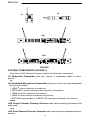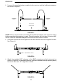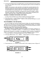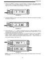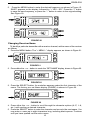
1
! IMPORTANT SAFETY INSTRUCTIONS ! This symbol indicates that there are important operating and maintenance instructions in the literature accompanying this unit. 1. 2. 3. 4. 5. 6. 7. 8. 9. 10. READ these instructions. KEEP these instructions. HEED all warnings. FOLLOW all instructions. DO NOT use this apparatus near water. DO NOT expose the apparatus to dripping and splashing. DO NOT put objects filled with liquids, such as vases, on the apparatus. CLEAN ONLY with a dry cloth. DO NOT block any of the ventilation openings. Install in accordance with the manufacturer’s instructions. Do not install near any heat sources such as radiators, heat registers, stoves, or other apparatus (including amplifiers) that produce heat. DO NOT defeat the safety purpose of the grounding-type plug. The third prong is provided for your safety. When the provided plug does not fit into your outlet, consult an electrician for replacement of the obsolete outlet. PREVENT the power cord from being walked on or pinched, especially at plugs, receptacles, and the point of exit from the apparatus. This symbol indicates that dangerous voltage constituting a risk of electric shock is present within this unit. 11. 12. USE only attachments/accessories specified by the manufacturer. USE only with a cart, stand, tripod, bracket, or table specified by the manufacturer or sold with the apparatus. When a cart is used, use caution when moving the cart-apparatus combination to avoid injury from tip-over. 13. UNPLUG this apparatus during lightning storms or when unused for long periods of time. 14. REFER all servicing to qualified service personnel. Servicing is required when the apparatus has been damaged in any way, such as when the power-supply cord or plug has been damaged, liquid has been spilled or objects have fallen into the apparatus, the apparatus has been exposed to rain or moisture, does not operate normally, or has been dropped. 15. DO NOT expose the apparatus to dripping and splashing. DO NOT put objects filled with liquids, such as vases, on the apparatus. WARNING: Voltages in this equipment are hazardous to life. No user-serviceable parts inside. Refer all servicing to qualified service personnel. The safety certifications do not apply when the operating voltage is changed from the factory setting. 2004, Shure Incorporated 27C8571 (Rev. 6) Printed in U.S.A. 1 ENGLISH TABLE OF CONTENTS SYSTEM DESCRIPTION . . . . . . . . . . . . . . . . . . . . . . . . . . . . . . . . . . . . . . . . . . . . . . . . . . . . . . . . 3 SYSTEM FEATURES . . . . . . . . . . . . . . . . . . . . . . . . . . . . . . . . . . . . . . . . . . . . . . . . . . . . . . . . . . . 3 SYSTEM COMPONENTS . . . . . . . . . . . . . . . . . . . . . . . . . . . . . . . . . . . . . . . . . . . . . . . . . . . . . . . 4 U1 BODY-PACK TRANSMITTER CONTROLS & INDICATORS . . . . . . . . . . . . . . . . . . . . . . . 5 U2 MICROPHONE-TRANSMITTER CONTROLS & INDICATORS . . . . . . . . . . . . . . . . . . . . . . 6 U4S & U4D RECEIVER CONTROLS & CONNECTORS . . . . . . . . . . . . . . . . . . . . . . . . . . . . 7 RECEIVER SETUP . . . . . . . . . . . . . . . . . . . . . . . . . . . . . . . . . . . . . . . . . . . . . . . . . . . . . . . . . . . . . 9 Installing Rear Mounted Receiver Antennas . . . . . . . . . . . . . . . . . . . . . . . . . . . . . . . . . . . . . . . 9 Installing Front Mounted Receiver Antennas . . . . . . . . . . . . . . . . . . . . . . . . . . . . . . . . . . . . . . 9 Basic Receiver Connections . . . . . . . . . . . . . . . . . . . . . . . . . . . . . . . . . . . . . . . . . . . . . . . . . . 11 VIEWING CURRENT RECEIVER SETTINGS . . . . . . . . . . . . . . . . . . . . . . . . . . . . . . . . . . . . . . 12 PROGRAMMING THE RECEIVER . . . . . . . . . . . . . . . . . . . . . . . . . . . . . . . . . . . . . . . . . . . . . . . 12 Changing Receiver Group/Channel Settings . . . . . . . . . . . . . . . . . . . . . . . . . . . . . . . . . . . . . 12 Changing Receiver Frequency Setting . . . . . . . . . . . . . . . . . . . . . . . . . . . . . . . . . . . . . . . . . . 14 Changing Receiver Name . . . . . . . . . . . . . . . . . . . . . . . . . . . . . . . . . . . . . . . . . . . . . . . . . . . . . Changing Receiver Squelch Level Setting . . . . . . . . . . . . . . . . . . . . . . . . . . . . . . . . . . . . . . . Locking the Receiver Display . . . . . . . . . . . . . . . . . . . . . . . . . . . . . . . . . . . . . . . . . . . . . . . . . Unlocking the Receiver Display . . . . . . . . . . . . . . . . . . . . . . . . . . . . . . . . . . . . . . . . . . . . . . . TRANSMITTER SETUP . . . . . . . . . . . . . . . . . . . . . . . . . . . . . . . . . . . . . . . . . . . . . . . . . . . . . . . . 15 16 18 19 20 Transmitter Battery Installation . . . . . . . . . . . . . . . . . . . . . . . . . . . . . . . . . . . . . . . . . . . . . . . . . Checking Transmitter Batteries . . . . . . . . . . . . . . . . . . . . . . . . . . . . . . . . . . . . . . . . . . . . . . . . Connecting a Lavalier Microphone or Instrument Cable to the U1 Transmitter . . . . . . . . . . . . . . . . . . . . . . . . . . . . . . . . . . . . . . . . . . . . . . . . . . . . . . . . . . . . . PROGRAMMING THE TRANSMITTER . . . . . . . . . . . . . . . . . . . . . . . . . . . . . . . . . . . . . . . . . . . 20 21 22 22 Changing Transmitter Group/Channel Settings . . . . . . . . . . . . . . . . . . . . . . . . . . . . . . . . . . . 22 Locking the Power Switch in the ON Position . . . . . . . . . . . . . . . . . . . . . . . . . . . . . . . . . . . . . 25 Cancelling the Power On Lock Function . . . . . . . . . . . . . . . . . . . . . . . . . . . . . . . . . . . . . . . . . Activating the Frequency Lock Function . . . . . . . . . . . . . . . . . . . . . . . . . . . . . . . . . . . . . . . . . Cancelling the Frequency Lock Function . . . . . . . . . . . . . . . . . . . . . . . . . . . . . . . . . . . . . . . . OPERATING THE U1 BODY–PACK SYSTEM . . . . . . . . . . . . . . . . . . . . . . . . . . . . . . . . . . . . . 25 26 27 27 OPERATING THE U2 HAND-HELD SYSTEM . . . . . . . . . . . . . . . . . . . . . . . . . . . . . . . . . . . . . 28 ADJUSTING TRANSMITTER AUDIO GAIN LEVEL . . . . . . . . . . . . . . . . . . . . . . . . . . . . . . . . . 29 ADJUSTING TRANSMITTER AUDIO INPUT LEVEL . . . . . . . . . . . . . . . . . . . . . . . . . . . . . . . . 30 TIPS FOR ACHIEVING OPTIMUM PERFORMANCE . . . . . . . . . . . . . . . . . . . . . . . . . . . . . . . . 31 TROUBLESHOOTING . . . . . . . . . . . . . . . . . . . . . . . . . . . . . . . . . . . . . . . . . . . . . . . . . . . . . . . 31 SPECIFICATIONS . . . . . . . . . . . . . . . . . . . . . . . . . . . . . . . . . . . . . . . . . . . . . . . . . . . . . . . . . . . . . 32 LICENSING INFORMATION . . . . . . . . . . . . . . . . . . . . . . . . . . . . . . . . . . . . . . . . . . . . . . . . . . . . 32 APPENDIX: NETWORK INTERFACE PIN MAP . . . . . . . . . . . . . . . . . . . . . . . . . . . . . . . . . . . . 33 2 ENGLISH SYSTEM DESCRIPTION The Shure UHF Wireless microphone system is a frequency-agile diversity system operating in the UHF band. Both the receiver and the transmitter are synthesizer controlled via Phase Locked Loop (PLL) circuitry for clear, steady radio frequency (RF) signal. The receiver is available in either dual or single models that fit into a standard 19 inch (482 mm) equipment rack. An auxiliary unswitched AC output jack allows multiple receivers to be linked “daisy chain” style. The optional UA830 Remote Antenna Kits can be powered by 12 Vdc, 500 mA output provided through the antenna connectors. The optional UA845 Antenna Distribution Amplifier Kits allows connection of multiple receivers using only two antennas. SYSTEM FEATURES Shure UHF Wireless Systems offer many exceptional features, including: • Menu Driven Display. User–programmable receiver display shows Group, Channel, Frequency, Name, Squelch level, and Locked/Unlocked status. • Exclusive Shure MARCAD Circuitry. MARCAD (Maximum Ratio Combining Audio Diversity) circuitry constantly monitors signals from both receiver sections and combines them in a single output signal. MARCAD provides superior reception and exceptional freedom from dropouts. • Noise Squelch Circuitry. Analyzes signal quality instead of signal strength. This virtually eliminates the possibility of annoying noise bursts coming through your receiver. • Dual RF Level Meters. The U4S and U4D receivers have two RF meters, one for each antenna. The dual meters indicate received signal strength at each antenna, and make it easier to identify and troubleshoot “dead spots”. • Audio Metering. Each receiver includes a seven–segment audio meter that lets you monitor audio level and helps optimize transmitter gain setting. • Transmitter Display. Shows Group, Channel, Battery Power Level, and POWER LOCK ON/OFF* condition. Both displays are user programmable. • Tone Key Squelch: Eliminates unwanted noise from entering system; eliminates popping noises when turning the transmitter on or off. • Dual Receiver Option: Provides greater flexibility while conserving rack space. • Preconfigured Group/Channel: Ensures frequency compatibility and simplifies system installation. • Network Expansion Capability. U4S and U4D receivers have a 25–pin serial connector for future computer control and monitoring via an accessory interface box. • DC/DC Converter: Ensures consistent audio and RF performance, even if battery voltages change. * U.S. Patent No. 5,692,057. 3 ENGLISH U2 U1 U4S U4D FIGURE 1 SYSTEM COMPONENTS (FIGURE 1) Each Shure UHF Wireless System includes the following components: U1 Body-Pack Transmitter with your choice of instrument cable or microphone, or U2 Hand-Held Microphone-Transmitter with your choice of interchangeable microphone heads: • SM58 cardioid dynamic microphone • BETA 58A supercardioid premium dynamic microphone • SM86 cardioid condenser microphone • SM87A supercardioid condenser microphone • BETA 87A supercardioid or BETA 87C premium condenser microphone; and a U4S Single Channel Diversity Receiver with rack-mounting hardware and antennas, or a U4D Dual Channel Diversity Receiver with rack-mounting hardware and antennas. 4 ENGLISH U1 TRANSMITTER CONTROLS & INDICATORS (FIGURE 2) a c de a b g ON h OFF i f j k l m FIGURE 2 1. Antenna: A flexible 1/4 wave whip antenna is permanently attached to the top of the U1 body-pack transmitter. A qualified technician can replace the antenna in the field. 2. Programmable Display: Displays group and channel, battery power level, and frequency lock/power lock on/off status. 3. Input Connector: Provides connection with a variety of lavalier and headset microphone cables, and the Shure WA302 instrument adapter cable. LEMO–type connectors are available as an option. 4. ON/OFF Switch: Turns transmitter power on and off. 5. On/Off LED: Glows green when the U1 is turned on. 6. Belt Clip: Allows the transmitter to be easily worn on a belt, waistband, or guitar strap. 7. MODE Button: Selects the parameter (Group or Channel) you wish to change. 8. SET Button: Changes transmitter Group and Channel settings. Also used with the MODE button to lock power on and to lock the frequency and channel setting. 9. Audio Gain Control: Allows audio level adjustment to accommodate a variety of sound sources (speaking, singing, or playing an instrument). A small screwdriver is supplied for making adjustments. 10. Battery Cover Release Tabs: Squeeze these two tabs together to release the battery cover. 11. Battery Compartment Cover: Hinged cover on front surface opens to expose the battery and display control keys. 12. Battery Fuel Gauge: Visually indicates battery power level. 13. Battery Compartment: Holds two 1.5V AA batteries. 5 ENGLISH a b c GAIN d j g h e i ON OFF f FIGURE 3 U2 TRANSMITTER CONTROLS & INDICATORS (FIGURE 3) 1. Grille: Protects the microphone cartridge and helps reduce breath sounds and wind noise. The grilles for the various microphone heads differ in appearance. 2. Programmable Display: Displays Group and Channel, battery power level, and frequency lock/power lock on/off status. 3. Battery Fuel Gage: Visually indicates battery power level. 4. Battery Cover: Unscrews to expose batteries and display control keys. 5. ON/OFF Switch: Turns transmitter power on and off. 6. Antenna: Helical antenna is attached to the end of the U2 transmitter. A qualified technician can replace the antenna in the field. 7. Battery Compartment: Holds two 1.5 V AA batteries. 8. MODE Button: Selects the parameter (Group or Channel) you wish to change. 9. SET Button: Changes transmitter Group and Channel settings. Also used with the MODE button to lock power on and to lock the frequency and channel setting. 10. Audio Gain Control: Allows audio level adjustment to accommodate a variety of sound sources (speaking, singing, or playing an instrument). A small screwdriver is supplied for making adjustments. 6 ENGLISH a m n o b c d p q r e f g h i j k l o s U4S Receiver a bc d m n e f g h a o bc d p q r e f g h i j k s pq r l o U4D Receiver FIGURE 4 U4S & U4D RECEIVER CONTROLS & CONNECTORS (FIGURE 4) 1. MENU Button: Press this button to access the main display menu. 2. SELECT Button: Press this button to choose or execute a displayed value or function. 3. RF Level Indicators: Five LEDs per RF antenna channel glow to indicate RF signal strength. The more LEDs that glow, the stronger the received signal. If none of these LEDs glow, no signal is being received. 4. Audio Level Indicators: These seven LEDs glow to indicate audio signal strength. Green indicates normal operation. Amber indicates approaching overload condition. Red indicates excessively high audio levels. (Clipping occurs within 4–6 dB when the red LEDs glow). 7 ENGLISH 5. Programmable Display: Displays group and channel number, frequency, squelch level, system name, transmitter battery power level, and display lock on/ off status. 6. + Button: Press this button to scroll display forward. 7. – Button: Press this button to scroll display backward. 8. Audio Output Control: Adjusts receiver output level to match input level requirements of a mixer or amplifier. Normally, this control is set fully clockwise. 9. Headphone Monitor Volume Control: Rotate this knob to the right to increase headphone volume; rotate it to the left to decrease headphone volume. NOTE: If you are using a Model U4S Receiver, press the Headphone Volume Control knob to turn the monitor on or off. If you are using a Model U4D Receiver, press the Headphone Volume Control knob once to select Receiver 1 or twice to select Receiver 2, depending on which section you wish to monitor. 10. Headphone Monitor Status: These LEDs glow yellow when the headphone monitor circuit is turned on or off. NOTE: The Tone Key feature is present only on the receiver output. As a result, you may hear an occasional “pop” through the headphones when the transmitter is turned on or off. 11. Headphone Input Connector: Plug headphones into this 1/4–inch connector to monitor receiver audio. 12. POWER On/Off Switch: Turns the receiver on and off. 13. Power Input Connector: Accepts power directly from any 90 to 230 VAC, 50/60 Hz power source. 14. Power Output Connector: Provides 90 to 230 VAC, 50/60 Hz power to additional equipment. It can be used to link multiple receivers or to power the Shure UA840 Antenna Distribution System. 15. Antenna Input Connectors: BNC-type connectors provide connection to the supplied antennas or to coaxial cable used with a distribution amplifier or remote antennas. CAUTION: To avoid damage to equipment, make sure any equipment connected to the antenna inputs can tolerate 12 VDC power. 16. HIGH Z (Unbalanced) Output Connector: 1/4 inch phone jack provides unbalanced auxiliary level (high-impedance) output. 17. Mic/Line Slide Switch: Controls output of balanced XLR connector. It can be set for microphone or line-level (microphone level = line level – 30 dB). 18. LOW Z (Balanced) Output Connector: XLR connector provides balanced lowimpedance mic level or line-level output. 19. Networking Interface: 25–pin “D” connector provides future electronic interface to computers and other equipment via accessory interface box. 8 ENGLISH RECEIVER SETUP Installing Rear Mounted Receiver Antennas Attach the supplied UHF antennas to the antenna BNC connectors on the receiver back panel, as shown in Figure 5. For best performance, orient the antennas with tips pointing away from each other at a 45° angle from vertical. FIGURE 5 Installing Front Mounted Receiver Antennas 1. Insert the two bulkhead adapters through the larger holes on each side of the front panel, and secure them from each side, using the supplied attaching hardware. See Figure 6. Ñ ÑÑÑÑÑÑÑÑÑÑ Ñ Ñ Ñ Ñ Ñ Ñ Ñ Ñ Ñ Ñ Ñ Ñ Ñ Ñ Ñ ÑÑ Ñ Ñ ÑÑÑÑÑÑÑÑÑÑÑÑÑ Ñ ÑÑÑ ÑÑ BULKHEAD ADAPTER RECEIVER (TOP VIEW) FIGURE 6 9 BULKHEAD ADAPTER ENGLISH 2. Connect the supplied antenna cables to the receiver and the bulkhead adapters, as shown in Figure 7. Ñ Ñ Ñ Ñ ÑÑÑÑÑÑÑÑÑÑ Ñ Ñ Ñ Ñ Ñ Ñ Ñ Ñ Ñ Ñ Ñ Ñ Ñ ÑÑ Ñ Ñ Ñ Ñ Ñ Ñ ÑÑÑ ÑÑÑÑÑÑÑÑÑÑÑÑÑ ÑÑÑÑÑÑÑÑÑÑÑÑÑ ÑÑ ÑÑÑ ANTENNA CABLE ANTENNA CABLE RECEIVER (TOP VIEW) FIGURE 7 NOTE: Shure recommends connecting the bulkhead adapter and antenna cables before mounting the receiver in a rack. Once the receiver is in the rack, it is more difficult to insert the bulkhead adapters and connect the antenna cables. 3. Insert the receiver into the equipment rack and secure it with the supplied screws. See Figure 8. EQUIPMENT RACK FIGURE 8 4. Attach the supplied UHF antennas to the BNC connectors on the front panel, as shown in Figure 9. For best performance, orient the antennas with tips pointing away from each other at a 45° angle from vertical. FIGURE 9 10 ENGLISH Basic Receiver Connections (Figure 10) 1. Connect the receiver output to the mixer or amplifier input, using a standard audio cable with a female 3-pin XLR connector or 1/4-inch phone plug. 2. If desired, plug a set of headphones into the headphone monitor output connector. HEADPHONES AC POWER AUDIO MIXER LOUDSPEAKER AMPLIFIER LOUDSPEAKER FIGURE 10 11 ENGLISH 3. Connect the female end of a modular power cord to the male power input connector on the rear panel of the receiver. Then plug the power cord into a suitable AC power source. NOTE: If the receiver is rack-mounted, or if using front–mounted antennas, the antennas should extend above the rack cabinet or be remotely located. Improved diversity performance may be obtained by installing one or both antennas at a remote location and separating them by 1.5 meters (60 inches) or more. Antennas at remote locations should be connected to the receiver via UA825 or UA850 Extension Cable Kit(s) or other suitable low-loss cable (RG8 or equivalent) and used in conjunction with a UA830 Active Remote Antenna Kit. VIEWING CURRENT RECEIVER SETTINGS To view current settings on the receiver display, proceed as follows: 1. Turn the receiver on by pressing upper half of the POWER switch. 2. Press either the “+” button or the “–” button on the receiver front panel to scroll through the current settings. PROGRAMMING THE RECEIVER You can change the receiver Group/Channel setting, the operating frequency, squelch level, and receiver name through the programmable display. The display can then be locked to prevent accidental changes. The following paragraphs present instructions for programming each display function. Changing Receiver Group/Channel Settings The receiver display identifies frequencies by Group and Channel, allowing convenient setup of compatible systems. A complete list of compatible frequency Groups and Channels is included in the separate UHF Frequency Compatibility Guide. To change the receiver Group and Channel settings, proceed as follows: 1. Turn the receiver on by pressing upper half of the POWER switch. 2. Press the MENU button. The “+ MENU –” display appears, as shown in Figure 11. FIGURE 11 3. Press either the + or – button to reach the SET G/CH display, shown in Figure 12. FIGURE 12 12 ENGLISH 4. Press the “SELECT” button to choose Group or Channel. The current Group, Channel, and TV channel setting appears, as shown in Figure 13. (Models sold outside the U.S. and Canada may not display TV channel.) GROUP CHANNEL TV FIGURE 13 5. Press the SELECT button until a line is below the character you want to change, as shown in Figure 14. GROUP CHANNEL TV FIGURE 14 6. Press either the “+” or “–” button to change the Group or Channel setting. The TV Channel setting will change automatically. (Models sold outside the U.S. and Canada may not display TV channel.) 7. When the new Group/Channel has been completely entered, press the MENU button. “SAVE?” appears on the display, followed by “+ YES – NO”. Press the “+” button to save the new Group/Channel setting or press the “–” button to return to the original setting. See Figure 15. FIGURE 15 NOTE: If more than 20 seconds of inactivity elapse, the display returns to the original settings. 13 ENGLISH Changing Receiver Frequency Setting 1. Press the MENU button. The “+ MENU –” display appears, as shown in Figure 16. FIGURE 16 2. Press either the + or – button to reach the SET FREQ display, shown in Figure 17. FIGURE 17 3. Press the SELECT button. The current operating frequency displays, as shown in Figure 18. FIGURE 18 4. Press the “+” or “–” button to increase or decrease the setting in incremental steps until reaching the desired frequency. See Figure 19. FIGURE 19 NOTE: The receiver operating frequency actually changes the moment you press the + and – buttons. As the frequency changes, the G/CH number automatically changes. By observing the RF lights on the receiver, you can see which frequencies are already being used and avoid interference. If more than 20 seconds of inactivity elapse, the display will return to the original settings. 14 ENGLISH 5. Press the MENU button to enter the desired frequency, as shown in Figure 15. SAVE? appears on the display, followed by “+ YES – NO”. Press the “+” button to save the new frequency, or press the “–” button to return to the original setting. See Figure 20. FIGURE 20 Changing Receiver Name To identify a particular transmitter with a receiver channel, set the name of the receiver as follows: 1. Press the MENU button. The “+ MENU –” display appears, as shown in Figure 21. FIGURE 21 2. Press either the + or – button to reach the “SET NAME” display, shown in Figure 22. FIGURE 22 3. Press the SELECT button. An underline appears under the first character of the name. The factory pre–set Name display (SHURE) is shown in Figure 23. FIGURE 23 4. Press either the + or – button to scroll through the character options (A–Z, 1–9, etc.) until reaching a desired character. 5. Press the SELECT button to enter the character and move to the next space. You may enter a name up to eight characters long, including blank spaces. Continue until you have spelled out the entire name. 15 ENGLISH 6. When the new name has been completely entered, press the MENU button. “SAVE?” appears, followed by “+ YES – NO”. Press the “+” button to save the new name and return to the Group/Channel/TV display. Press the “–” button to make more changes. See Figure 24. FIGURE 24 NOTE: If more than 20 seconds of inactivity elapse, the display will return to the original settings. Changing Receiver Squelch Level Setting Higher squelch settings demand a quieter signal before muting the receiver, but reduce operating range. Lower squelch settings extend the operating range, but increase noise levels before dropout occurs. To change the receiver Squelch setting, proceed as follows: 1. Press the MENU button. The “+ MENU –” display appears, as shown in Figure 25. FIGURE 25 2. Press either the + or – button to reach the “SET SQCH” display, shown in Figure 26. FIGURE 26 3. Press the SELECT button to display the current squelch level, as shown in Figure 27 (factory preset value is “0.0”). MID FIGURE 27 4. Press either the “+” or “–” button to change the Squelch setting in increments of 0.5 until reaching the desired level. The Squelch setting actually changes the moment you press the “+” and “–” buttons. 16 ENGLISH NOTE: The highest possible squelch setting is +10.0 and the lowest possible squelch setting is –10.0, as shown in the following table . However, the factory preset level of 0.0 usually will not need to be changed.* Receiver Squelch Control Settings DISPLAY Maximum 10 9.5 9.0 8.5 8.0 7.5 7.0 6.5 6.0 5.5 5.0 4.5 4.0 3.5 3.0 2.5 2.0 1.5 1.0 0.5 Midrange 0 –0.5 –1.0 –1.5 –2.0 –2.5 –3.0 –3.5 –4.0 –4.5 –5.0 –5.5 –6.0 –6.5 –7.0 –7.5 –8.0 –8.5 –9.0 –9.5 Minimum –10 dBm* –83.0 –86.0 –87.0 –87.5 –88.0 –88.5 –89.0 –89.5 –90.0 –90.5 –91.0 –91.5 –92.0 –92.3 –92.7 –93.0 –93.3 –93.6 –93.9 –94.2 –94.5 –94.8 –95.1 –95.4 –95.7 –96.0 –96.3 –96.6 –96.9 –97.2 –97.5 –97.8 –98.1 –98.4 –98.7 –99.0 –99.3 –99.6 –99.9 –100.2 Open *U4S and U4D squelch values differ slightly. Specifications subject to change without notice. 17 ENGLISH 5. Once you have reached the desired squelch level, press the MENU button. “SAVE?” appear, followed by “+ YES – NO”, as shown in Figure 28. Press the – button to make more changes, or press + to save the new squelch setting and return to the Group/Channel/TV display. FIGURE 28 NOTE: If more than 20 seconds of inactivity elapse, the display returns to the original settings. Locking the Receiver Display 1. Press the MENU button. The “+ MENU –” display appears, as shown in Figure 29. FIGURE 29 2. Press either the + or – button to reach the “SET LOCK” display, as shown in Figure 30. FIGURE 30 18 ENGLISH 3. Press the SELECT button. The “CODE?” display appears, as shown in Figure 31. FIGURE 31 4. Press +, –, +, in that order, to engage the display lock. The display shown in Figure 32 appears. FIGURE 32 NOTE: Write down the lock code (+, –, +) and keep it in a secure place. If no code is entered, the system times out and return to the main display. 5. A small “lock” symbol appears in the upper right corner of the status screen displays, as shown in Figure 33. The lock symbol indicates the receiver is in the lock mode. GROUP CHANNEL TV FIGURE 33 Unlocking the Receiver Display To disengage the lock, press the MENU button. When “CODE?” appears, press +, –, + , in that order, then press the MENU button. NOTE: Once the lock function is engaged, any attempt to change settings causes “CODE?” to appear. If the incorrect code is entered, “INVALID” appears, preventing the user from changing any settings. 19 ENGLISH TRANSMITTER SETUP Transmitter Battery Installation (Figure 34) 1. Make sure the transmitter power ON/OFF switch is in the OFF position. 2. Open the transmitter battery compartment as follows: • U1 Transmitter: Squeeze the two tabs on either side of the transmitter and flip the battery cover down. • U2 Transmitter: Unscrew the battery cover and slide it down. 1.5V AA 1.5V AA 1.5V AA 1.5V AA FIGURE 34 3. Remove the old batteries as follows: • U1 Transmitter: Press down on the negative terminal end of each battery. • U2 Transmitter: Lift the batteries out. 4. Install two fresh 1.5 V AA alkaline batteries. Make sure the battery terminals match the terminals in the transmitter. 5. Close the battery cover. IMPORTANT: Two fresh 1.5 V AA alkaline batteries should provide 8 to 12 hours of operation. However, nickel-cadmium (nicad) batteries may only provide up to 3 hours of operation. Carbon-zinc and zinc-chloride batteries will not provide sufficient power, and are not recommended. 20 ENGLISH Checking Transmitter Batteries (Figure 35) 1. Turn the transmitter power ON/OFF switch to the ON position. 2. Observe the battery fuel gauge displayed on the transmitter screen and on the right side of the receiver screen. The number of black segments displayed indicates battery power level. As transmitter batteries are consumed, the displayed segments will gradually disappear. NOTE: The dc to dc converter functions keeps system voltage constant as battery voltage declines, ensuring superior audio and RF performance. Number of Segments Displayed on Transmitter Operating Time Remaining (in Hours)* 5 4 3 2 1 8 – 12 6–8 4–6 2–4 1 or less *Using alkaline batteries. TRANSMITTER BATTERY FUEL GAUGE (ON TRANSMITTER DISPLAY) Number of Segments Displayed on Receiver Operating Time Remaining (in Hours)* 3 2 1 0 4 – 12 2–4 2 or less 0.5 or less *Using alkaline batteries. TRANSMITTER BATTERY FUEL GAUGE (ON RECEIVER DISPLAY) FIGURE 35 NOTE: If the transmitter is left on and the batteries run down, the microprocessor turns off RF power, the Tone key, and the display. 21 ENGLISH Connecting a Lavalier Microphone or Instrument Cable to the U1 Transmitter (Figure 36) 1. Plug the microphone cable or instrument cable into the transmitter input connector. 2. Attach the lavalier microphone to your tie, shirt, or collar. If using a headset, put the headset on. 3. If using an instrument adapter cable, attach the other end of cable to the instrument output connector. MICROPHONE CABLE OR INSTRUMENT ADAPTER CABLE FIGURE 36 PROGRAMMING THE TRANSMITTER The Group/Channel setting on the U1 and U2 transmitter display can be programmed to meet the requirements of a particular installation. You can also lock the display and the power on function to prevent accidental changes. The following paragraphs present instructions for programming the transmitters. Changing Transmitter Group/Channel Settings 1. Turn the transmitter on by sliding the transmitter power ON/OFF switch to the ON position. The existing Group and Channel settings automatically display. 2. Open the battery compartment. This will expose the MODE (left) and SET (right) buttons, as well as the GAIN control and the batteries, as shown in Figure 37. FIGURE 37 22 ENGLISH 3. Press and hold down the MODE button until only the Group number displays, as shown in Figure 38. FIGURE 38 4. Press the SET button to increment the Group setting, as shown in Figure 39. FIGURE 39 NOTE: If the SET button is held for more than 5 seconds, the display goes into the fast increment mode. If more than 20 seconds of inactivity elapse, the display returns to the original settings. 23 ENGLISH 5. Press the MODE button again so that only the Channel number displays, as shown in Figure 40. FIGURE 40 6. Press the SET button to change the Channel setting, as shown in Figure 41. FIGURE 41 7. Press the MODE button again so that the new Group and Channel numbers both display. NOTE: On transmitter, the transmitter operating frequency does not change until new settings are saved. 24 ENGLISH Locking the Power Switch in the ON Position To lock the power switch, press and hold the SET button, then press and hold the MODE button. Hold both keys down until “PoL” (for power locked) displays, as shown in Figure 42. FIGURE 42 NOTE: When the Power On Lock function is activated, “–– ––” will flash on the transmitter screen every 5 seconds when the transmitter power ON/OFF switch is in the OFF position. CANCELLING THE POWER ON LOCK FUNCTION To cancel the Transmitter Power On Lock unction, press and hold the SET button, then press and hold the MODE button. Keep both keys pressed down until “Po UL” (for power unlocked) displays momentarily, as shown in Figure 43.The Transmitter Power On Lock function can also be cancelled by removing the batteries. FIGURE 43 25 ENGLISH Activating the Frequency Lock Function The Frequency Lock function prevents accidental frequency changes, and is particularly useful in preventing accidental or unauthorized changes. The lock function is retained in memory, even if the transmitter is turned off and the batteries removed. To activate the Frequency Lock function, proceed as follows: 1. Turn the transmitter power off. 2. Turn the power back on while holding down the SET button until the fuel gauge on the transmitter is active. “Fr L” appears momentarily, as shown in Figure 44, until you release the SET button. FIGURE 44 3. To verify that the frequency lock function is turned on, press the MODE or SET button. If the lock function is turned on, “– –” appears on the transmitter screen, as shown in Figure 45. FIGURE 45 26 ENGLISH NOTE: When the Frequency Lock function is engaged, the Power On Lock function can still be activated. However, if the Power Lock and the Frequency Lock functions are engaged, the Power Lock function must be disengaged before cancelling the Frequency Lock. Cancelling the Frequency Lock Function (Figure 46) To cancel the Frequency Change Lock function, repeat the steps in the preceding Activating the Frequency Lock Function paragraph. When the frequency lock function is turned off, Fr UL will appear on the transmitter display, as shown in Figure 46. FIGURE 46 OPERATING THE U1 BODY–PACK SYSTEM 1. Clip the U1 body pack transmitter to your belt, waistband, or guitar strap. Push the body pack all the way down. 2. Connect the lavalier microphone, headset microphone, or instrument adapter cable to the U1 transmitter. 3. If using a lavalier microphone, clip it to your tie, lapel, or other garment. If you are using a headset, put the headset on. If using an instrument adapter cable, plug it into the instrument. 4. Slide the transmitter power ON/OFF switch to the ON position. The green power on LED glows and the Group and Channel number appears on the transmitter display, along with a bar graph indicating battery power level. 27 ENGLISH 5. Turn the receiver on by pressing the upper section of the POWER switch. The receiver display and RF LEDs glows. 6. Make sure the transmitter and receiver are tuned to the same Group, Channel, and Frequency. If necessary, change the settings on either the transmitter or receiver. 7. If using a headphone monitor, push the monitor knob on the receiver (U4S) or half the way down (U4D). The headphone monitor light, located below the knob, glows. Rotate the knob until the headphone volume is at a comfortable level. NOTE: If using the U4D receiver, pushing this knob selects the receiver section you wish to monitor. 8. Begin speaking or playing your instrument. Rotate the OUTPUT LEVEL knob as necessary to achieve desired receiver output levels. NOTE: If the red PEAK LEDs on the receiver do not flicker during the loudest sounds, or if they are always on, the transmitter gain may require increasing or decreasing. Refer to Adjusting the Transmitter Audio Gain Level. If the system still does not operate properly, consult the Troubleshooting table. 9. When the performance or presentation is over, slide the transmitter ON/OFF switch to the OFF position to conserve battery power. OPERATING THE U2 HAND-HELD SYSTEM 1. Slide the transmitter power ON/OFF switch to the ON position. The Group and Channel number appears on the transmitter display, along with a bar graph indicating battery power level. 2. Turn the receiver on by pressing the upper section of the POWER switch. The receiver display and the RF lights glows. 3. Make sure the transmitter and receiver are tuned to the same Group, Channel, and Frequency. If necessary, change the settings on the transmitter or receiver. 4. If using a headphone monitor, push the monitor knob on the receiver to turn the monitor circuit on. The ON LED, located below the knob, glows. Rotate the knob until the headphone volume is at a comfortable level. NOTE: If using the U4D receiver, pushing this knob selects the receiver section you wish to monitor. 5. Begin speaking or singing into the microphone. Rotate the OUTPUT LEVEL knob as necessary to increase or decrease receiver output levels. NOTE: If the red PEAK LEDs on the receiver do not flicker during the loudest sounds, or if they are always on, the transmitter gain may require increasing or decreasing. Refer to Adjusting the Transmitter Audio Gain Level. If the system still does not operate properly, consult the Troubleshooting table. 6. When the performance or presentation is over, slide the transmitter power ON/ OFF switch to the OFF position to conserve battery power. 28 ENGLISH ADJUSTING TRANSMITTER AUDIO GAIN LEVEL (FIGURE 47) The transmitter audio gain level has been factory pre-set to provide satisfactory output in most applications. However, for loud singers or high-output musical instruments, the preset level may be too high, as indicated by constant glow of the red audio level LED. Soft-spoken talkers or singers may find that the factory setting is too low, as indicated by the failure of the amber audio level LED to glow at all. To adjust audio gain, open the battery compartment and locate the transmitter audio gain control. Use the supplied screwdriver to make adjustments. DECREASE GAIN Ñ INCREASE GAIN DECREASE GAIN INCREASE GAIN FIGURE 47 S For high sound pressure level applications, such as loud singing or playing, decrease audio gain level by rotating the gain control counterclockwise (while the microphone is in use) until the red audio level LEDs on the receiver flickers during the loudest sounds. S For low sound pressure level applications, such as soft singing or playing, increase audio gain level by rotating the gain control clockwise until the red audio level LEDs on the receiver flickers during the loudest sounds. NOTE: For guitar applications, the minimum setting (full counterclockwise) is recommended. If using the Shure WH20TQG headset, rotate the gain control to the full clockwise position. Then, if necessary, rotate it back slightly. 29 ENGLISH ADJUSTING TRANSMITTER AUDIO INPUT LEVEL (FIGURE 48) NOTE: The factory-preset (–6 dB) should match most applications. Before changing the audio input level, try adjusting the transmitter gain (see Figure 47). The U1 body-pack transmitter has an attenuator switch allowing you to set the audio input level for different types of applications. Use one of the following three settings according to the type of input source used: • 0 dB (fully counterclockwise) is for low-output microphones, such as those in headsets. • –6 dB (center) is the factory-preset position; it should accommodate most vocal and instrumental applications. • –20 dB (fully clockwise) is for extremely high-output instruments, such as electric guitars with active electronics. To change the audio input level, re-position the attenuator switch using the following steps: 1. Remove the belt clip from the back of the transmitter by carefully prying the wire bracket, one side at a time, from the sides of the transmitter. Removing the clip reveals an access hole in the back of the transmitter. Increase input level Decrease input level Attenuator access Clip sockets FIGURE 48 2. Use the supplied 1.6 mm (1/16 in.) flat blade screwdriver to turn the Attenuator control fully clockwise (–20 dB), fully counterclockwise (0 dB), or center (–6 dB). In the center detent position, the screw slot is horizontal when the transmitter is upright. 3. Readjust the Gain pot so the red “Audio” LED on the U4 receiver flickers only occasionally at the strongest peaks during a performance (see Figure 47). 4. Orient the belt clip so that “Shure” is on the outside and toward the top (antenna side) of the transmitter. Carefully reinsert the clip’s wire bracket, one side at a time, into the body of the transmitter. 30 ENGLISH TIPS FOR ACHIEVING OPTIMUM PERFORMANCE S Maintain a line-of-sight between the transmitter and receiver antennas. Avoid placing transmitter and receiver where metal or other dense materials may be present. S Avoid placing the receiver near computers or other RF generating equipment. S Avoid placing the receiver in the bottom of an equipment rack unless the antennas are remotely located. S Use the proper receiver antennas. S Point the antenna tips away from each other at a 45° angle from vertical, and keep them away from large metal objects. S Maintain a distance of at least 10 ft between the transmitter and receiver to prevent overloading the receiver. S Do not obstruct the transmitter antennas with your hands. S Use the proper cable when remotely locating receiver antennas. For best performance, use Shure UA825 or UA850 low loss coaxial antenna cable, or 50Ω low loss cable such as RG8. S Use Shure UA830 Active Remote Antenna Kit for remote antenna placement. S Mount diversity antennas at least 1/4 wave apart, although spacing of 1.5 m (60 inches) or more is preferred. Achieve this by remote placement of one or both antennas using Shure UA825 or UA850 low–loss coaxial cable and a Shure UA830 Active Remote Antenna Kit. For multiple system installations, use the Shure UA845 Antenna/Power Distribution System. TROUBLESHOOTING The following table identifies some common problems and their solutions. If unable to solve a problem, contact your dealer or the Shure Service Department at 1-800-516-2525 (7:30 am to 4:00 pm, Central Standard Time). In Europe, call 49-7131-72140; other international users call Shure in the U.S.A. at 847-600-2000. Problem Solution No sound; receiver RF light(s) and AUDIO LEDs not glowing. Make sure Power switches on transmitter and receiver are on. Check transmitter Power/Battery Fuel Gauge. Replace battery if necessary. Make sure transmitter and receiver frequency Group/Channel settings are identical. Check receiver squelch setting. Check receiver antenna connection(s). Make sure at least one antenna is in the line of sight of the transmitter. If necessary, reduce the distance between transmitter and receiver. 31 ENGLISH Problem Solution No receiver sound; RF and Audio Level meter LEDs glowing. Turn up the receiver audio output Level control. Check for proper connection between receiver and microphone mixer. Talk into the microphone and observe the receiver audio level LEDs. If they glow, the problem is elsewhere in the sound system. Received signal is noisy or contains extraneous sounds with transmitter on. Check transmitter Power/Battery Fuel Gauge and replace battery if power is low. Remove local sources of RF interference, such as lighting equipment. If using a guitar or other instrument, make sure it is connected to the U1 with a Shure WA302 adapter cable. Two transmitters may be operating on the same frequency. Locate and turn one off or change frequency. Signal may be too weak. Reposition antennas closer to the transmitter. Adjust receiver squelch control. Noise from receiv- Adjust receiver squelch control. er with transmitter Remove local sources of RF interference, such as lighting equipment. off. Try using another frequency. Reposition the receiver or antennas. Momentary loss of sound as transmitter is moved around performing area. Reposition receiver and perform another “walkthrough” test and observe the RF level or Diversity signal indicators. If audio dropouts persist, mark these “dead spots” in the performing area and avoid them during the performance. Decrease squelch control setting, even though noise in “dead spots” may increase slightly. Move antennas to a remote location (use UA830 kit). SPECIFICATIONS Refer to the supplement that came with your system. LICENSING INFORMATION Changes or modifications not expressly approved by Shure Incorporated could void your authority to operate the equipment. Licensing of Shure wireless microphone equipment is the user’s responsibility, and licensability depends on the user’s classification and application, and on the selected frequency. Shure strongly urges the user to contact the appropriate telecommunications authority concerning proper licensing, and before choosing and ordering frequencies other than standard frequencies. 32 ENGLISH APPENDIX: NETWORK INTERFACE PIN MAP The U4S and U4D receivers both have a 25–pin network interface located on the rear panel. The interface allows future monitoring and control of all receiver functions, including audio level, RF level, and “A/B” diversity indication, from a remote location via an interface device. The table below identifies the signal output by each pin on the connector. Contact you Shure dealer for addition information. NOTE: Using any of the pins in the shaded area could result in system malfunction or damage to your receiver. Pin Receiver 1 (Left) Receiver 2 (Right) Connection 1 Ground Ground 2 Audio Meter Analog 3 RF Level B 4 RF Level A 5 Connection Type Impedance Voltage Range Not Applicable 0V Output 1.2 kΩ 0–2 V Typical 0–5 V Maximum Analog Output 2.5 kΩ 1–4 V Analog Output 2.5 kΩ 1–4 V Diversity B Analog Output 2 kΩ 1–4 V 6 Diversity A Analog Output 2 kΩ 1–4 V 7 Network Interrupt Digital Input Not Applicable 1–4 V 8 Network Interrupt Digital Output/Busy Not Applicable 1–4 V 9 Serial Data Output Digital Output Not Applicable 1–4 V 10 Serial Data Input Digital Input Not Applicable 1–4 V 11 5V Not Applicable 5V 12 5V Not Applicable 5V Not Applicable 1–4 V 13 5V (indicates unit is dual channel) 14 Audio Meter Analog Output 1.2 kΩ 0–2 V Typical 0–5 V Maximum 15 RF Level B Analog Output 2.5 kΩ 1–4 V 16 RF Level A Analog Output 2.5 kΩ 1–4 V 33 ENGLISH Pin Receiver 2 (Right) Connection Connection Type Impedance Voltage Range 17 Diversity B Analog Output 2 kΩ 1–4 V 18 Diversity A Analog Output 2 kΩ 1–4 V Digital Input Not Applicable 1–4 V 19 Receiver 1 (Left) Serial Clock 20 Serial Clock Digital Input Not Applicable 1–4 V 21 Network Interrupt Digital Input Not Applicable 1–4 V 22 Network Interrupt Digital Output/Busy Not Applicable 1–4 V 23 Serial Data Output Digital Output Not Applicable 1–4 V 24 Serial Data Input Digital Input Not Applicable 1–4 V Not Applicable 0V 25 Ground Ground 34 SHURE Incorporated Web Address: http://www.shure.com 5800 W. Touhy Avenue, Niles, IL 60714-4608, U.S.A. Phone: 1-847-600-2000 Fax: 1-847-600-1212 In Europe, Phone: 49-7131-72140 Fax: 49-7131-721414 In Asia, Phone: 852-2893-4290 Fax: 852-2893-4055 Elsewhere, Fax: 1-847-600-6446