1
00000
OD
139
1
1 39°53606
1 39.5361 0
- 1/3HP
- 1/2 HP
= 1/2 HP
° 1/3 HP
Owners
Manual
CAUTION
READ INSTRUCTIONS
FOR SAFE OPERATION
AND RULES
CAREFULLY
CONTENTS
PAGE
Features of Your Opener .............
Specifications
..........................
Accessories
...............................
Carton Check List ......................
You'll Need Tools ....................
Safety Rules ..............................
Operation
of Your Opener ............
Maintenance
Schedule
...............
Assembly
Installation
Information .................
Installation
...........................
Force& Limit Adjustment
............
Safety Reverse Test ......................
Setting/Changing
Code ................
Having a Problem? .....................
Repair Parts, Rail Assembly ...........
Repair Parts, Installation
..............
Repair Parts, Chassis Assembly
.....
How to Order Repair Parts ...........
Maintenance
Agreements
Sears Warranty .........................
..................................
...........
2
2
2
3
3
4
5
5
6
9
9
17
18
19
20
22
22
23
24
24
24
FASTEN OWNERS MANUAL NEAR GARAGE DOOR AFTER INSTALLATION
IS COMPLETE.
PERIODIC CHECKS OF THE OPENER ARE REQUIRED TO INSURE SATISFACTORY
OPERATION.
FEATURES
OF YOUR
OPENER
1.
Motor: Permanently
reset,
lubricated with automatic
5.
2.
Opener
Light: Turns on and off automatically.
Provides 4-1/2 minute illumination for your safety
and convenience,
6.
3.
Safety System:
Independent up and down force
adjustment.
Door reverses automatically
when
obstructed in DOWN direction Door STOPS when
obstructed
in UP direction
4.
7.
8.
EasyLimitAdjustment:
Limitsofdooropening
and closing adjusted by turning screws without
removing chassis cover
Digital Radio Controls: The code can be easily
changed by the owner
3_Channel
Transmitter:
Three push buttons,
Each button can activate one or more remote
control devices The large transmitter
button is
factory preset to operate the garage door opene_
Emergency
Disconnect:
Pullcord disconnect
permits manual door operation,
Automatic
Reconnect:
The trolley halves reconnect for automatic operation when opener is
energized after emergency disconnect
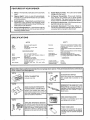
SPECIFICATIONS
MOTOR
Type .
Speed
Vofts
....
Current
.....
Door linkage
....
Push button & automatic
direction
Push button
tn up direction
Independent
up & down
screws
Motor overload protector
push button wiring
Circuit actuated by limit
Screwdriver
adjustment
Low voltage push button
Electronic
MECHANISM
Electrical
Limit
Limit
Start
16:1 worm gear reduction
Chain & cable with two*piece
trolley on
steel Tee rail
Adjustable
to 7-1/2 feet
6 to 8 inches per second
On when door starts in travel, off 4-1/2
minutes after stop
Adjustable
door arm
Pug cord troUey
release
Length of Travel
Travel rate
Lamp ....
Sears
stock
Personal
Permanent
split capacitor
1500 rpm
120 Volts AC - 60 Hz Only
45 amperes
DRIVE
Gears
Drive
SAFETY
offers
many useful accessories
numbers
and descriptions,
for your
device
adjustment
circuil
.
force
adjustment
and low voltage
nut
on side panel
or radio control
DIMENSIONS
Length (overall)
.
Headroom
required
Hanging Weight
garage
door
53718
opener.
They
124 in
2 inches
32 pounds
are
illustrated
below
with
Sears
53703
EXTRA TRANSMITTER:
Includes visor clip
Opens he garage doer automat ca ly
from outside when transmitter
is not
OUTDOOR KEY SWITCH:
handy
53709
53702
EMERGENCY
(FOR SECTIONAL
DOORS
ONLY}
Replace top brackets
and rollers on
doorto
height ofBRACKETS:
door travel For
DOOR reduce
CLEARANCE
use when installing opener in garage
with low headroom clearance
_/_
REQUIRED fora garage
......................................................................................
53717
• !_
. ._ii_E_.._
53710
INFRARED
t_'.
I_l'Ybzm
REVERSING
KEY LOCK:
OPEN
DOOR
with NO set-
INDICATOR:
your garage door is open
Provides an illuminated
signal
when
SENSOR:
iliary support to the safety features
into your opener
If the sensor's
An optional system which provides
reverse and an open door will not
ible beam is broken,
RELEASE
vice door° Allows manual operation of
garage door from outside in ease of
power failure
......_-7
"_
reversal in down
& automatic
stop
a closing
built
53716
invis_
TOUCH CODE LOCK:
aux ...........................................................................................
close
garage door opener from outside by
entering the
code homeowner
on specially todesigned
door will
_
Enables
operate
keypad
2
i
CARTON
CHECK
LIST
SEARS has packaged yourGarage
Door Opener
illustrated
below and on Page 22.
Sprocket
Cover
SEPARATE
Rail
Grease
ALL HARDWARE
ASSEMBLY
in two cartons
Light
FOR ASSEMBLY
which contain
all the parts and hardware
Transmitters
{2)
Model 13953413
(1 ONLY)
Touch Code Lock (1)
Model 139 53610 ONLY
Lens (1)
AND INSTALLATION
HARDWARE
PROCEDURES
INSTALLATION
AS SHOWN
BELOW.
HARDWARE
Clevis Pin
5/16" x 2-3/4"
Lockwasher
5116"(3)
(_
5116"-18x2-1/2"
Washered
Screw
5/16"18xl/2'"
Master Link
(2)
Ring or
Cotter Pin
Fastener(3)
*(2 mounted
in Chassis)
(41
5!16"
- 18xl-7/8"'
(4)
Nut
8ABxl
(2)
'
Insulated
Staple (18)
Handle
5/16 (B)
"_ 18
Carriage
Bolt
1/4''_20xl/2"
(4)
_f _
©
Hex Screw
_
5/16" x 1"
Clevis
(2) Pin
5/16"-18x7/8"
(2)
Lock Nut
1/4" -20
(4)
_re
w
× 7/8"
5/16"-18
Nut
5/16"-18
Lock Washer
5/15"(6)
(6)
(4)
YOU'LL
NEED
TOOLS
During assembly and installation of you r opener, the instructions will call for use of various hand tools, Have a
stepladder handy, and those tools illustrated below: hammer, electric drill (& 3/1 6" and 5/1 6" drill bits), screwdriver, adjustable end wrench or socket wrench kit, wire cutters, tape measure, pliers and hack saw
Hack
Pliers
Tape
Saw
Measure
Wire Cutters
Claw Hammer
Screwdriver
Stepladder
Electric
Drill
Socket
Wrench
3
Adiustable
End Wrench
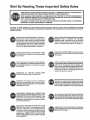
Start By Reading These Impo ant
Safety Rules
THIS SAFETY ALERT SYMBOL MEANS CAUTION -- PERSONAL SAFETY OR PROPERTY
DAMAGE INSTRUCTION.
READ THESE INSTRUCTIONS
CAREFULLY°
THIS GARAGE DOOR OPENER
IS DESIGNED
AND TESTED TO OFFER REASONABLY
SAFE SERVICE
PROVIDED
IT IS INSTALLED
AND OPERATED
IN STRICT ACCORDANCE
WITH TH E FOLLOWING
SAFETY INSTRUCTIONS.
FAILURE TO COMPLYWITH
THE FOLLOWING
PERSONAL
INJURY OR PROPERTY DAMAGE,
CAUTION:
IF YOUR GARAGE HAS NO SERVICE
KEYLOCK (PAGE 2). THIS ACCESSORY
ALLOWS
POWER FAILURE.
INSTRUCTIONS
MAY RESULTIN
SERIOUS
ENTRANCE
DOOR, INSTALL
MODEL 53702
EMERGENCY
RELEASE
MANUAL OPERATION
OF GARAGE DOOR FROM OUTSIDE
IN CASE OF
DO NOT USE FORCE ADJUSTMENTS
TO COMPENSATE
FOR A BINDING
OR STICKING
GARAGE DOOR. Excessive
force will Interfere
KEEP GARAGE DOOR BALANCED°
Sticking
or
binding doors must be repaired.. Garage doors,
door springs, cables, pulleys, brackets and their
hardware may be under extreme tension and can
cause serious personal injury. DO NOT ATTEMPT
ADJUSTMENTS.
Call a garage door seP_iceman
to move or adjust door springs or hardware_
with the proper operation
of the safety reverse
system or damage the garage door° (Page 17)..
Fasten
DO NOT WEAR RINGS, WATCHES
OR LOOSE
CLOTH ING while installing or servicing a garage
door opener.
the CAUTION
LABEL
on the wall nearthe
lighted wall control as a reminderof
procedures.
To avoid serious personal injury from entanglement, REMOVE
ALL ROPES CONNECTED
TO
THE GARAGE DOOR before installing the garage
door opener.
safe operating
Installwallcontrol(or
additional push buttons) IN
A LOCATION WHERE GARAGE DOOR ISVISIBLE,
BUT OUT OF THE REACH OF CHILDREN.
DO
NOTALLOWCHILDREN
TOOPERATETHEWALL
PUSH BUTTON(S)
OR TRANSMITTER.
personal
injury from a closing garage
result from misuse of opener..
Serious
door may
DISENGAGE ALL EXISTING GARAGE DOOR
LOCKS to avoid damage to garage door,,
CAUTION: Activate opener onlywhen the door is in
fu II view, free of obstm ctio n an d opener is properly
adjusted°
NO ONE SHOULD ENTER OR LEAVE
THE GARAGE WHILE DOOR IS IN MOTION°
DO
NOT ALLOW CHILDREN
TO PLAY NEAR DOOR°
Installation
and wiring must be in compliance
with your local building
and electrical
codes.
CONNECT
POWER CORD ONLYTO A PROPERLY
GROUNDED
OUTLET.
LIGHTWEIGHT
FIBERGLASS,
ALUMINUM
AND
STEEL DOORS MUST BE SUBSTANTIALLY
REINFORCED
TO AVOID DOOR DAMAGE.
(See
page 15.) The best solution is to check with you r
garage door manufacturer
for an opener installa o
tion reinforcement
kit_
THE
SAFETY
REVERSE
SYSTEM
TEST
IS IM*
PORTANT. (See Pg.18). Your garage door MUST
reverse on contact with a one*inch obstacle placed
on the floor_ Failure to properly adjust the opener
may result in serious personal injury from a closing
garage door., REPEAT TEST AT LEAST ONCE
EVERY THREE MONTHS
AND MAKE NEEDED
ADJ USTMENTS_
Use emergency release ONLY to disengage trolley
and, if possible,
ON LY when the door is closed.
DO NOT USE RED EMERGENCY
RELEASE ROPE
AND HANDLE TO PULL DOOR OPEN OR CLOSED
_
DISCONNECT
ELECTRIC
DOOR OPENER BEFORE
REMOVING
COVERS..
POWER
MAKING
TO GARAGE
REPAIRS OR
Operation
of Your Opener
CAUTION
e BEFORE YOU PROCEED,
PLEASE READ THE SAFETY
RULES ON PAGE 4 AND OPERATING
INSTRUCTIONS
ON THIS PAGE CAREFULLY.
• DO NOT PERMIT
CHILDREN
TO PLAY IN DOOR
AREA.
• OPERATEONLYWHENTHEOPENERISPROPERLYADJUSTED AND DOOR IS WSIBLE AND UNOBSTRUCTED.
e TO AVOID DIFFICULTY
DURING
INSTALLATION,
DO
NOT RUN OPENER UNTIL INSTRUCTED
TO DO SO.
IJSING
THE
OPENER
WHEN
Your opener can be activated by any of the following
(wait one-second
between
commands):
devices
1
The transmitter.
(The TOP (large) push button has been
factory preset to operate door) Hold push button down
until door starts to move
2
The lighted
wall control,
starts to move
Hold button
down
until door
3 The Key Switch orTouch Code Lock(if you have installed
either of these accessories)
OPENING
THE
DOOR
Simply pull down sharply on red emergency
release handle
and lift the door manually
To automatically
reconnect
the
door to the opener, press the wall control push button
DO NOT USE THE EMERGENCY
DOOR OPEN OR CLOSED
HANDLE
TO PULLTHE
IS ACTIVATED:
I
If open, door will close
2
If closing,
3
If opening, the door will stop (allowing
exit of pets and for fresh air)
4
If the door has been stopped
will close
5
If an obstruction
will reverse
is encountered
6
If an obstruction
will stop
is encountered
7
[f the optional Infrared Reversing Sensor is installed, the
garage door will reverse in the closing cycle when the
invisible beam is broke n An open doorwill not close when
the beam is broken The sensor has no effect in the opening cycle
MANUALLY
The door can be operated manually by disconnecting
it from
the opener THE DOOR SHOULD
BE FULLY CLOSED IF
POSSIBLE, WEAK OR BROKEN SPRINGS COULD ALLOW
AN OPEN DOOR TO FALL RAPIDLY. PROPERTY DAMAGE
OR SERIOUS
PERSONAL
INJURY COULD RESULT.
OPENER
if closed,
door will open
the door will reverse
space for entry and
in a partially
while
while
open position,
it
closing,
the door
opening,
the door
THE OPENER LIGHT will turn on under the following
conditions: when the opener is initially plugged in; when power is
interrupted;
when the opener is activated. It will turn off automatically after 4-1/2 minutes. Bulb size-75 Watts maximum
CARE OF THE OPENER
When properly installed, the opener will provide high performance with a minimum
of maintenance
Opener does not
require additional
lubrication
Most complaints
of unsatisfactory
opener operation
can be
traced to problems with the door itself....OPENER
IS NOT
INTENDEDTOCORRECT
PROBLEMSTHATARECAUSED
BYAN UNBALANCED
OR BINDING DOOR, BROKEN DOOR
SPRINGS OR BY FAULTY DOOR HARDWARE.
When operated manually, a properly balanced door will stay
in any point of travel while being supported
entirely by its
springs
LIMIT AND FORCE ADJUSTMENTS:
These adjustments
must be checked and properly set when opener is installed,
Only a screwdriver
is required
Weather
conditions
may
cause minor changes in door operation
requiring some
re-adjustments,
particularly during the first year of operation. Page 17 refers to limit and force adjustments. Follow
instructions carefully and repeat SAFETY REVERSE TEST
after any adjustment
THE SAFETY REVERSE
SYSTEM
IS IMPORTANT
(SEE
PG.18)., GARAGE DOOR MUSTREVERSE
ON CONTACT
WITH A ONE-INCH
OBSTACLE
PLACED ON THE FLOOR.
FAILURE TO PROPERLYADJUSTOPEN
ER MAY RESULT
IN SERIOUS PERSONAL INJURY FROM A CLOSING GARAGE DOOR.
CHAIN TENSION
ADJUSTMENT:
After installation of the
opener and adjustment
of forces and limits, chain may appear
loose This is normal
MAINTENANCE
AT LEAST4
MANUALLY
OPERATE
ing, call for professional
CHECK
FULLY.
TIMES
DOOR.
garage
A YEAR
If it is unbalanced
door service
TO MAKE SURE DOOR OPENS AND
Adjust Limits and/or Force if necessary
REPEAT SAFETY REVERSE
adjustments
(see page 18)
TEST.
TO CHECK THE CHAIN TENSION:
by pulling the red emergency
handle
the position described
and illustrated
NOT make ANY further adjustments.
THE TRANSMITTER:
The 3-channel
transmitter
will operate
more than one garage door opener, if desired. The additional
push buttons may also be used to operate other remote control devices. Transmitter(s)
may be secured to a car sun visor
with clip(s) provided. Additional transmitters can be purchased
at any time (Refer to Accessories,
Pg_ 2)
Any new transmitters
must be set to the same code as original
transmitter
and receive_
Page 19 explains
how to change
your existing code and how to use the transmitter(s)
with
other remote control devices Self service of your radio controis is not recommended
If service is needed, contact your
nearest Sears Service Center
TRANSMITTER
BATTERY: The 9-Volt battery should pred_ce power for approximately
one year As long as there is
adequate
power, the transmitter
battery test light will glow
when a push button is pressed (and the opener will operate)
When the light does not come on, replace battery If transmission range lessens, check battery light
Avoid the inconvenience
of unexpected
failure by replacing
battery annually,
preferably
before winter
Use a general
purpose, 9 volt battery
TO CHANGE
BATTERY:
Remove visor clip and connecting
screw in transmitter
case Set aside top of case and discard
old battery
Snap connector
onto new battery Replace top of
case and connecting
screw Replace visor clip,
OF YOUR
OPENER
TWICE
or bind-
CLOSES
Make any necessary
disconnect
the trolley
If the chain returns to
in Step 5 Page 9, DO
CHECK CHAIN TENSION.
ONCE
A YEAR
Adjust if necessary
A YEAR
OIL DOOR ROLLERS, BEARINGS AND HINGES,
REPLACE THE TRANSMITTER
fore winter
BATTERY, preferably be-
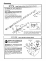
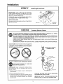
Assembly
TO AVOID INSTALLATION
INSTRUCTED
TO DO SO.
ST
_: P
DIFFICULTIES,
"1
DO NOT
Assemble
RUN THE
GARAGE
Tee Rail & Attach
DOOR
Cable
OPENER
UNTIL
YOU ARE
Pulley Bracket
TEE RAIL BACK
(TO CHASSIS)
CAUTION: Do not tighten the lock nuts until bolt
necks are seated in square holes.
Tee Rail
(End Section)
t/4'
Lock Nut
Carriage Bolt
/2"
Tee Rail
Brace
_
PROCEDURE:
Place the 3 Tee rail sections on a flat
surface for assembly. THIS IS IMPORTANT. The end
sections are identical. THE CENTER SECTION MUST BE
POSITIONED WITH THE BRACES ON THE LEFT SIDE OF
END SECTIONS. If there is a label attached to the center section, make sure that the "directional
arrow" is
pointing toward the front (to door) Otherwise, study
the illustration
CAREFULLY
The center rail section MUST be
positioned on the LEFTSIDE of end
rails as shown,
Otherwise, trolley will hit against nut
when installed (Pg. 7).
Brace
(When assembled,
Tee rail has a front-to-back
tion as shown).
Bolt rail sections together with the hardware
trated and from the direction indicated
SQUARE
SEATED
NECKS
ON CARRIAGE
BOLTS
MUST
IN SQUARE HOLES IN RAIL SECTIONS,
posiillusBE
Screws
Tee Rail
(End Section)
Square Carriage
Bolt Hole
_
Cable
Pulley
_5/16"_18x7/8""
_
_,_';
Cable pulley bracket
attaches to FRONT
END of Tee Rail
k°ckW_s--_her_l
TEE
RAIL FRONT
(TO DOOR)
5/16"
_
Nut
5/16"
Position cable pulley bracket on front end of tee rail as
shown. Fasten securely with the hardware provided
IMPORTANT:
Whentighteningscrews,
besureto
keep bracket parallel to rail, Otherwise,
rail may
bow when opener is operated.
6
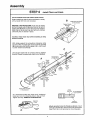
Assernbiy
STE P 2
Install
Trolley
& Attach
Chain
Retainer
Bracket
As a temporary
stop, insert a screwdriver
into
hole in front end of Tee rail as shown. Slide the
inner trolley onto the Tee rail until it is firmly against
the screwdriver
NOTE: If trolley hits against nut on Tee rail, center
section was attached from wrong side and must
be repositioned.
Review Step 1.
Slide the outer trolley onto the Tee rail until it partially
engages the inner trolley and stops
TO FULLY ENGAGE
TROLLEY:
With a hammer,
firmly tap the back end of outer trolley just below the
rail guide Outer trolley must move forward to fully
engage inner trolley Be careful to avoid damaging
trolley spring,
Outer Trolley
Inner
Trolley
Outer
Nut
Lock Washer
5/16"
Temporary
Stop
Screwdriver
Inner
Nut
Chain
Retainer
Bracket
Cable
Pulley
Bracket
Threaded
End
\
Trolley
Shaft
Attach inner nut, lock washer, chain retainer bracket
and outer nut to trolley shaft in the order shown_ DO
NOT TIGHTEN NUTS UNTIL STEP 5, PAGE 9,
Flat End
STE P 3
._5/16"
r
Attach
Tee Rail to Opener
Washered Screw
5/16"-1Sxl/2"
USE ONLYTHOSE
SCREWS MOUNTED
IN TOPOFOPEN
ER CHASSIS.
FAILURE
TO DO SO WILL CAUSE SERIOUS DAMAGE TO THE DOOR OPENER°
PROCEDURE:
Place opener chassis
on packing
ma terial to protect cover For convenience,
place a
support under the cable pulley bracket
Re move 5/16"-18xl/2"
washered screws mounted
in top of opener chassis Align holes in back end of
Tee ran with holes in opener chassis. Fasten the rail
to the chassis with washered
screws previously
removed. CAUTION: USEONLYTHESESCREWS!
Use of any other screws will cause serious damage to door opener. Tighten screws securely,
insert a 5/16"-18xl/2"
washered screw into trolley
stop hole in the Tee rail as shown, Tighten securely
with a 5/16" nut
Chassis
Stop Hole
Tee Rall
(Back Sectior
5/16"-18
7
Assembly
STE P 4
I.stallChain
andCable
DO NOT REMOVE CHAIN AND CABLE FROM CARTON
Detach cable from side of carton and fasten to trolley
with a master link from coin envelope
I=!
install Chain andCable
inThisDirection
Opener Chassis
Sprocket
/
MASTER LINK PROCEDURE:
Push pins of master
link bar through loop of cable and hole in flat end of
trolley shaft (A) Push cap over pins and onto notches.
Slide clip-on spring over cap and onto pin notches
until both pins are locked in place,
Caution:
Keep chain
prevent kinking,
taut while
installing
to help
With trolley against the screwdriver,
dispense cable
around pulley Proceed back around opener sprocket
(B) - be sure sprocket teeth engage chain - and forward
to chain retainer bracket (C).
C
Use second master link to connect chain to retainer
bracket. Check to make sure chain is not twisted.
Th_reo_rde_dsEhndTee Rail
_
j
Chain
A
Master
Link
Clip-On
Spring
Retaai_eetr
End
ear
Trolley
Master
Link
Outside
Bar
Pulley
Install Chain and Cable
in This D{recl[on
Trolley
St°P_H
¢_
As a permanent trolley stop, insert 5/16" washered
screw and nut into remaining hole in Tee rail front
Tighten securely REMOVE SCREWDRIVER.
5S/'C
r6ewWaan'h
_ruetd
\
Remove
Screwdriver
Tab
Slot
Plate
Attach sprocket cover to chassis as shown, Insert
back tab in chassis slot Then bend cover forward and
insert front tab in slot provided on mounting plate
Assembly
STE P 5
Loosen
Inner
Nut
Tighten
the Chain
and Cable
CAUTION:
Keep
are turned.
Tighten
Outer
Nut
PROCEDURE:
shown (Loosen
the chain
from twisting
as nuts
Thread the outer nut toward trolley as
inner nut first, if"necessary)
Tension is correct when the chain is approximately
1/2" above base of Tee rail midway between cable
pulley bracket and chassis.
Trolley
To maintain proper tension, turn inner nut toward chain
retainer bracket until tight
Chain
Sprocket
noise can
loose or too tight.
1/2 Inch
CAUTION:
J
Base of Tee Rail "
ASSEMBLY
BEFORE
COMPLY
OF YOUR GARAGE
DOOR OPENER
YOU PROCEED WITH THE INSTALLATION
WITH THE FOLLOWING
SAFETY RULES:
result
if chain
Do not overtighten
Refer to Page 5.
is either
chain
and
too
cable.
IS NOW COMPLETE.
OF YOUR GARAGE
DOOR OPENER
BE SURE TO
KEEP GARAGE DOOR BALANCED.
STICKING
OR BINDING
DOORS MUST BE REPAIRED. THE
GARAGE DOOR, THE DOOR SPRINGS, CABLES, PULLEYS, BRACKETS AND TH EIR HARDWARE
MAY BE UNDER EXTREME TENSION
AND CAN CAUSE SERIOUS PERSONAL
INJURY. DO NOT
A'FFEM PTADJUSTM ENTS. CALLA GARAGE DOOR SERVICEMAN
TO MOVE, LOOSEN OR ADJUST
DOOR SPRINGS OR HARDWARE.
DO NOT WEAR WATCHES,
DOOR OPENER.
RINGS OR LOOSE CLOTHI
AS YOU PROCEED WITH THE REMAINING
HELPFUL TO REFER TO THE FOLLOWING
GARAGE DOOR OPENER.
Cable
INSTRUCTIONS
ILLUSTRATION
NG WHILE
INSTALLING
OR SERVICING
IN THIS OWNERS MANUAL,
OF THE FULLY ASSEMBLED
YOU MAY FIND IT
AND INSTALLED
Pulley
Bracket
A
Power Cord
Trolley
Hanging
Bracket
Chain
and Cable
\
3-Piece
Tee Bait
Sprocket
Cover
Header
Bracket
Chain
Retainer
Bracket
Straight
LightLens
o
Curved
Door
Arm
Emergency
Trolley
Release
o
Chassis
Door Brackel
and Plate
IT IS RECOMMENDED
THAT
WHERE SPACE PERMITS..
CERTAIN
INSTALLATION
DIFFERENCES
OCCUR,
DOOR CONSTRUCTION..
THE
OPENER
BE INSTALLED
PROCEDURES
VARY ACCORDING
BE SURE TO FOLLOW ONLYTHOSE
9
7 FEET
OR MORE
ABOVE
THE
FLOOR
TO GARAGE DOOR TYPES, WHERE THE
I NSTRUCTIONSWHICH
APPLY TO YOUR
installation
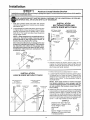
STE P 1
Installation procedures
your door as illustrated
Position
vary according
below.,
& Install
Header
Bracket
to garage door types. Follow onlytbose
instructions
which applyto
THE HEADER BRACKET MUST BE RIGIDLY FASTENED
TO TH E H EADER WALL OR CEILING,,
REINFORCE
WALL OR CEILING WITH 2x4 IF NECESSARY,
I NSTALLATION
SECTIONAL
DOOR AND
1-PIECE
DOOR WITH TRACK
1 With door closed, locate and mark the vertical
centerline of garage door Extend line onto header
wall above door
2, Locate height for header bracket by opening door
to highest point of travel as shown, Draw an intersecting horizontal
line on header wall 2" above
high point This height provides travel clearance
for top edge of door
NOTE: When headroom
is not su fficient for 2"
clearance,
the bottom edge of bracket may be
placed parallel
to the high point of travel, or
bracket
may be attached
to ceiling.
SECTIONAL
DOOR
CURVED TRACK
Ceiling
_
Header
BrackeI
Header
Bracket
Track
I
Highesl Point
of Travel
Door Clearance
Brackets are designed
for low
headroom
installations(Page
2). They replace
top brackets
and rollers on the garage door,
thereby lowering
the high point of door travel.
Installation
instructions
are contained
in the
accessory ca_on,,
Header
ONE*PtECE
DOOR
HORIZONTAL
TRACK
JAMB HARDWARE
_/
Door
of Travel
Highest Point
/,
Track
-Door
//
j
/
Lag Screws
5/16"-18x17/8
3 Position
bracket as shown (bottom edge of the
bracket on horizontal
line) Mark either top and
bottom or left and right bracket holes Drill 3/16"
pilot holes and fasten bracket
Highesl
Point ol
Travel
I
1-PIECE
I NSTALLATION
DOOR WITHOUT
ONE'PIECE
DOOR
NO TRACK
JAMS HARDWARE
ONE PIECE DOOR
NO TRACK
PIVOT HARDWARE
Header
Z Bracket
TRACK
Highesl
Point
Header
Bracket
J
of Travel
\
Point
of Travet
i',
Do(
Highest
'_
DOOr
q
_
II
0
.Jamb
Follow instructions
as described
in 1 above
2 Locate height for header bracket by opening door
to highest point of travel as shown Measure the
distance from top of door to floor Subtract actual
height of door Add 8" to the remainder
Refer to
example below
NOTE: If the total number of inches exceeds
the height
available
in your garage,
use the
maximum
height possible,, On finished ceilings,
do not position
the bracket
closer than 1/2"
from ceiling,
3 Measuring from top of door, draw an intersecting
horizontal line on header wall at determined height
Position bottom edge of header bracket on the
horizontal line, centering
bracket on vertical line
Mark either top and bottom or left and right holes
Drill 3/16" pilot holes and fasten the bracket with
5/16" x 1-7/8" lag screws as shown above,
EXAMPLE
._
Distance from top of door (at
highest point of travel) to floor
Actual height of door
Remainder
Add
Bracket height on header wall
(Measure UP from top of door
in closed position_)
10
92"
-88"
4"
+ 8"
=12"
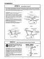
installation
STE P 2
Clevis Pin
5/16 'x2-3/4
@/_
A.ach
Tee Rail
Cotter
Ring OrpinI
Fastener
to Header
Bracket
PROCEDURE:
Position opener chassis on garage
floor below header bracket. Use packing material
base to protect cover NOTE: To enable Tee rail to
clear sectional
door springs, it may be necessary
to lift the chassis onto a temporary
support.
CAUTION: Chassis must either be secured
to the
support or held firmly in place by another person_
Raise Tee rail until cable pulley and header brackets
come together
Align bracket holes and join with
clevis pin as shown. Secure with a ring or cotter pin
fastener(if
cotter pin is used, spread to secure)
g Malerial
STE P 3
Follow
instructions
which
Position
Chassis
Opener
apply to your door type as illustrated
TO PREVENT
DAMAGE TO ALL LIGHTWEIGHT
NOT REST THE OPENER ON THE DOOR.
SECTIONAL
and ONE-PIECE
DOOR WiTH TRACK
I NSTALLATION
DOORS AND
below
DOORS
WITH
WINDOWS,
DO
ONE-PIECE
DOOR
WiTH NO - TRACK
i N STA LLATI ON
NOTE: A 2x4 is convenient
for setting
an ideal
door-to-Tee
rail distance.
It is not necessary where
headroom
is insufficienL
PROCEDURE:
Measure the distance from floor to
top of door (in fully open position and parallel to the
floor)
PROCEDURE:
Raise the opener chassis onto a stepladder Open garage door Place a 2x4 on edge on
top section of door near centerline
Rest Tee rail
on 2x4
Using a stepladder
as a support, raise the opener
chassis to the same distance from the floor (chassis
will have a slight angle as shown)
The top of the door should be levet with the top of the
opener For maximum efficiency, do not position the
opener chassis more than 2 inches above this point.
Tee Rail
2x4
Header
Bracket
•
TOp Of ODenet
Door
I
I
r_
I
I
I
11
Bracket
D
I
Equal
D_stance
lrom
Floor
_
I
I
I
installation
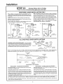
STEP 4
THE OPENER CHASSIS MUST BE
Three representative
installations
(Fig. 1 ) or crossed (Fig. 2) to provide
(not supplied) to ceiling joists before
Hang
Opener
Chassis
SECURELY
FASTENED TO A STRUCTURAL
SUPPORTOF
GARAGE.
are shown. You rs may be different. Hanging brackets should be angled
rigid support On finished ceilings (Fig. 3). attach a sturdy metal bracket
installing opener
FIGURE
2
FIGURE
3
PROCEDURE:
On EACH side of opener measure the
distance from chassis to structural support
Cut both pieces of the hanging bracket to required
lengths. Flatten one end of each bracket and bend or
twist to fit fastening angles. Do not bend at bracket
holes. Drill 3/16" pilot holes in structural
support.
Attach flattened ends of brackets to the support with
5/1 6"xl-7/8"
lag screws
Lift opener and
Checkto make
REMOVE 2x4.
the rail, raise
5/16"-18x7/8'"
Screw
5J
5/16"-18
fasten to hanging bracket as shown
sure Tee rail is centered over door.
Operate door manuaNy If door hits
header bracket.
Grease top and underside of rail surface on which
trolley slides. A tube of grease is supplied.
FIGURE
1
Bracket
(Net Supplied)
FINISHED CEILING
Lag Screws
5/16"xl-7/8"
Lag Screws
5/16"xl-7/8"
_
\
_
5/156/;L.°ClkV_auSth
er
Measure
Distance
STE P 5
Attach
Emergency
Release
Rope & Handle
USE EMERGENCY
RELEASE ONLY TO
DISENGAGE
TROLLEY.
DO NOT USE
ROPE AND HANDLE
TO PULL DOOR
OPEN OR CLOSED°
Overhand
PROCEDURE:
Thread one end of rope through hole
in top of red handle so'NOTICE' reads right side up as
shown Secure with an overhand knot NOTE: Knot
should be at least 1 inch from end of rope to pre.
vent slipping.1 Thread other end of rope through hole
in release arm of outer trolley Adjust rope length so
that handle is 6 feet above the floor. Secure with an
overhand knot as above.
Tr_o_ey
Release
Rope
NOTE: If it is necessary
to cut rope, heat seal cut
end with a match or lighter to prevent fraying and/
or raveling.
Overhand
Knot
12
_
--
Knot
Arm
LOCATE WALL PUSH BUTTON (OR ANY ADDITIONAL PUSH BUTTONS) WHERE GARAGE
DOOR IS VISIBLE, AWAY FROM DOOR AND DOOR HARDWARE AND OUT OF THE REACH
OF CHILDREN.
SERIOUS PERSONAL INJURY FROM A MOVING GARAGE DOOR MAY RESULT FROM MISUSE OF THE OPENER° DO NOT ALLOW CHILDREN TO OPERATE WALL PUSH BUTTON(S)
OR THE TRANSMITTER.
FASTEN THE CAUTION LABELON THE WALL NEAR WALL PUSH BUTTON AS A REMINDER
OF SAFE OPERATING PROCEDURES.
Top
installation
PROCEDURE: Remove about a 1/4" of insulation
from each end of the 2-strand bell wire_Connect one
end to the screw terminals on the back of wall control
as shown
Fasten the wall control to an inside garage wall with
the 8ABxl" sheet metal screws provided A convenient place is beside the service door and OUT OF
THE REACH OF CHILDREN,
Run the bell wire up the wall and across the ceiling to
garage door opener Use insulated staples to secure
wire,
The receiver terminals and the antenna are located
on the back panel of the opener chassi& Position
antenna wire as shown_ Then connect wire by color
to the white and red opener terminal screws,
2_Strand
Bell Wire
Wall
Control
Terminals
Bottom
Installation
Ftange
Opener
Staples
Terminal Screws
Wail Control
Push Button
OPERATION
Press and release
OF THE
Back Panel
of Opener
LIGHTED
to open or dose
WALL
CONTROL
WIRING
door
Press and release again to REVERSE door during CLOSING
to STOP door during OPENING cycle
NOTE: Wait about 1-second between commands.
Antenna
INSTRUCTIONS
Open
cycle or
FOR ACCESSORIES
Door
Indicator:.
TO white & orange opener terminals
Outdoor
Key Switch:
To red & white opener terminals
Touch
Code
Lock:
TO red and white opener terminals
Infrared
Reversing
To while & black opener
!3
r_
System:
terminals
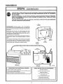
Installation
STE P 7
Install
Light and Lens
PROCEDURE:
Install a light bulb, (75 Watts Maximum) in socket as shown The light will turn on and
remain lit for 4-!/2 minutes when power is connected
After 4-1/2 minutes it will turn off
If light bulb burns out prematurely
tion, replace with a "rough service"
INSTALLING
Guide
Len
due to vibrabulb.
LENS:
Slide lens into the lens guides as shown Snap bottom
tabs into lens slots
Lighl Lens
STE P 8
_ab
_
75LightWattBulbMaX
Connect
Electric
Power
TO AVOID SERIOUS
PERSONAL
INJURY FROM ENTANGLEMENT,
REMOVE
CONNECTED
TO THE GARAGE DOOR BEFORE OPERATING
OPENER.
ALL ROPES
TO AVOID DAMAGE TO GARAGE DOOR AND OPENER, MAKE DOOR LOCKS INOPERATIVE
BEFORE CONNECTING
ELECTRIC
POWER. USE A WOOD SCREW OR NAIL TO HOLD THE
LOCKS IN "OPEN"
(UNLOCKED)
POSITION°
INSTALLATION
AND WIRING
MUST BE IN COMPLIANCE
WITH LOCAL ELECTRICAL
AND
BUILDING
CODES.
OPERATION
AT OTHER THAN 120V 60Hz WILL CAUSE OPENER
Opener MUST be permanently wired or plugged into
a grounded 3-prong receptacle
wired according
to
local electrical codes DO NOT use a 2-wire adapter
DO NOT use an extension cord
MALFUNCTION
AND DAMAGE.
PERMANENT
WIRING
CONNECTION
Ground
Tab
iround
RIGHT
Ground
IF LOCAL
CODES
REQUIRE
PERMANENT
DISCONNECT
POWER
BEFOREPROCEEDING.
PROCEDURE:
Refer to illustration
tion through the 7/8 inch diameter
opener chassis
1 Remove opener
cover screws
2 Remove
Screw
WRONG
attached
chassis
3-prong
cover
Wire
WIRING:
AT FUSE
BOX
Make connechole in top of
Wife
by removing
the
cord
CAUTION:
BE SURE THAT UNIT IS GROUNDED
ACCORDING
TO LOCAL CODE,
3 Connect the black (line) wire to the black wire on
terminal block; white (neutral) wire to the white
terminal wire; the green (ground) wire to green
ground screw
IMPORTANT
NOTE: TO AVOID INSTALLATION
DIFFICULTIES,
DO NOT RUN OPENER
NOW.
14
Installation
STE P 9
Follow
instructions
Install
Door Bracket
and Plate
which apply to your door type as illustrated
below
TO PREVENT DAMAGE TO LIGHTWEIGHT
GARAGE DOORS, ALWAYS REIN FORCETHE
OF DOOR--BOTH
VERTICALLY AND HORIZONTALLY--WITH
2x4 BOARDS OR ANGLE
INSIDE
IRON.
Horizontal brace should be at least 6 feet long Vertical brace should cover height of top panel The best solution
is to check with your garage door manufacturer
for a door reinforcement
kit for an opener installation.
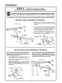
Sectional
SECTIONAL
Door Installation
1
Assemble the door bracket and plate as shown.
Center bracket on previously
marked vertical
guideline
2
Position bracket assembly on face of door within
the following limits: A. Top edge of bracket 2" to
4" below the top edge of door B. Directly below
any structural support across top of door
Placement depends on your particular
needs
3
Mark and drill 5/1 6" TOP and BOTTOM
ing holes Secure bracket as shown
DOOR
Header
gracket
Header
Waii
Vertical _
Center_._ _
Line
_
I
I
I
I
Door Brackel
I
Procedure
&
Door
Plate Assy
=_ _=Y
Carriage Boll.
6/16 ,.18x2.!/2-_
""
Bracket
-- _.
Door Bracket
...
Washer
Lock
5/16"
Door
Arm
Board for
Lightweight
AiD One-Piece
Inside
Doors
NOTE: The door bracket
has left and right side
fastening
holes, Assemble
and install
the door
bracket and plate if your installation
requires top
and bottom fastening
holes.
Center bracket (with or without plate as required)
on top edge of door as shown Mark holes
2_
Drill two 5/1 6" holes and fasten
with hardware supplied
Edge
of Door or Board
Reinforcement
Door Installation
1
fasten-
_.
5/16"-!8
Procedure
NOTE:
Door bracket may be installed
on face of
door if required
for your installation.
(Refer to
dotted line drawing,)
HOWEVER,
drill3/1
6" pilot
holes and substituteS/1
6"xl -1/2" lag screws(not
supplied)
to fasten the bracket to door,
door bracket
ONE PIECE DOOR
NOTE: If the door has no exposed
framing.
drill 3/16" pilot holes and use 5/16"x1-1/2"
lag screws (not supplied)
to fasten bracket to
top of door.
Header
Bracket
t
Door
Header
Wall
I
Nut
Door Bracket
Plate
Door
Arm
Door
Bracket
5/16"
Top Edge
of Door
(Outside)
Vertical
Center
Line
Optional)
I
i
(_/
Carriage
Door Bracket
Plate
(Optional)
Face of Door
Installation
Bolt
6/16'-18x2-1/2"
15
-
installation
STE P 10
Follow
only
Connect
those
instructions
SECTIONAL
DOOR
to your
type
ONLY
Pull the emergency
release
rope to disengage
trolley.
Bring arm sections together and insert screw into second
of holes Instalf lock washer and nut Tighten screws
Proceed to Step 1, Pg. 17. The trolley
automatically
when opener is operated.
as far
will
set
re-engage
C
B
A
door
FIG. C. If holes do not line up as shown in FIG, B, cross door
arms in scissor fashion When one set of holes lines up, insert
screw and 'finger tighten' with a lock washer and nut
Find two pairs of holes
Insert screws from straight arm side Select holes
apart as possible to increase door arm rigidity
apply
INSTALLATION
FIG, A. Make sure garage door is closed tight, Connect
straight door arm section to trolley with a clevis pin. Secure
with a ring or cotter pin fastener(if
cotter pin is used, spread
to secure)
Fasten curved section to door bracket in the same way
FIG,, B. Bring arm sections together
that line qp and join sections
Door Arm to Trolley
which
-Rope
Ring or
Cotter Pin
Fastener_
Lock
_s
Pin
!,_
Clevis
Release Hand{e
_
Straight
"-_
Curved
Door Arm
Door Arm
Pin-
Nu{
lency
/
Door
Bracket"
Washel
5/t6 '
Screwsx 7/85/16"q8
5/16"!8
B_acke{
ALL ONE-PIECE
DOOR
INSTALLATIONS
Ring or
ASSEMBLE
DOORARMPROCEDURE:Connectstraight
BDa°_re_
_°i!_nPin
wL°l_ekrs
" _ _
___-_"
lengthcurved
With door
door arm
closed,
connect
straightto door
arm possible
sect ion
and
sections
together
longest
to door bracket with a clevis pin Secu re wit h a ring or cotter
pin fastener (if cotter pin is used, spread to secure )
5/N_'!-s'8
5116"
I/_
5/16,,.18 x 7/8" ----_ _
Before
screws
connecting
are located
door arm to trolley,
limits of travel must be adjusted
on one-piece
doors, Limit
on left side panel of opener as shown
in illustration
on Pg. 1 7. Follow
procedures
adjustment
below
Fully Closed
Trolley
FuIly Open
Trolley
Door Arm
. _.:Z[
.:::Z_*--"
:
i
' i Connector
DOOr Arm
Hole
.
L
Closed
Open
Decrease
clockwise
DOOR
up limit. Turn UPlimit
4 complete
turns
Press Wall Control
button
Arm
LJ
PROCEDURES
PROCEDURE
ADJUSTMENT
adjustment
Trolley
I)oor
Door
Arm
Bracket
ADJUSTMENT
OPEN
.
Door
[_ Door
PROCEDURE-
_
Co nr_n°°rt^or r_o_
Decrease
clockwise
screw counter-
will travel
Press Wall Control
to full open
- CLOSED
DOOR
ADJUSTMENT
down limit, Turn DOWN limit adjustment
8 complete
turns
button
Trolley
will travel
screw
to full close
ManuaIly close door and lift door arm to trolley Arm should
touch trolley just ahead of door arm connector hole as shown
in dotted line drawing
If arm is behind the connector
hole,
adjust limit further
One ful! turn pqual_ 2 inches of door
travel
Manually raise door to open position (parallel to floor) and lift
door arm to trolley The arm should touch trolley just in back
of door arm connector
hole as shown in solid line drawing If
arm does not extend far enough, adjust limit furlher One fult
turn equals 2 inches of door travel
CON N ECT BOOR ARM TO TROLLEY: With door closed, join curved arm to connector
pin Secure with ring or cotter pin fastener
NOTE: It may be necessary
to llft door
Run opener throught a complete travel cycle
limits until door is parallel to floor
If top of door has a sli0 _ , aownward'
16
hole in trolley with remaining clevis
slightly
to make connection,,
slant in lull open
position,
decrease
UP
Adjustment
STEP 1
AdjustUPandDOWN
Limits
LIMIT ADJUSTMENT
settings regulate the points at which
the door will stop when moving up or down
NOTE:
Door STOPS
in UP direction
if anything
inter-
_
o _'_"_
direction if anything interferes with door travel (including binding or unbalanced
doors).
fereswithdoortraveI.
The door REVERSES
in DOWN
button or transmitter.
Run opener pressWa,,Contre,
through a COMPLETE
PROCEDURE:Tooperateopener,
push
TRAVEL CYCLE Limit adjustments are not necessary when
the door opens and closes completely
and does not reverse
unintentionally
in down direction
Limit
"Adjustment
Screws
w_-_
,,=,_
-- _--_
7
_/
i/.(
_
_¢4"._
._.___
°""'_*"
Left Side
Panel
before
proceeding
to Step 2_ Use a screwdriver[
LIMIT
If door doesn't open at least 5 feet:
as explained
in Step 2
IF DOOR
Lengthen
ADJUSTMENT
adjust OPEN FORCE
travel Turn down limit adjustment
screw
One turn equals 2 inches of travel
IF DOOR REVERSES
WHEN
IS NO INTERFERENCE
CLOSING
AND THERE
TO TRAVEL CYCLE
Test door for binding:
Pull emergency
release handle
Manually
open and close door If door is binding, call a
door serviceman
the door arm (See Step lg, Page 16)
If door arm is at maximum
length, increase DOWN travel
Turn down limit adjustment
screw counter clockwise
One
turn equals 2 inches of travel
If door is not binding
See _Step 2
If door still will not close completely,
the header
positioned
too high Repeat Step 1, Page 10
Decrease
clockwise
bracket
IF OPENER
is
STEP 2
Adjust
DO NOT USE FORCE ADJUSTMENTS
TO COMPENSATE
EXCESSIVE
FORCE WILL INTERFERE
WITH PROPER
DAMAGE GARAGE DOOR.
or unbalanced,
REVERSES
adjust CLOSE
IN FULLY
CLOSED
POSITION
screw
Force
FOR A BINDING
OR STICKING
GARAGE DOOR.
OPERATION
OF SAFETY REVERSE
SYSTEM OR
Force
Adjustment
. Controls
NOTE: Door STOPS in UP direction
if anything
interferes with door travel,, The door REVERSES
in DOWN
direction
if anything
interferes
with door travel (including binding
or unbalanced
doors).
If force adjustments
are set too fight, door travet may be
interrupted
by nuisance
reversals in DOWN direction
and
stops in UP direction
As weather conditionscan
affect door
movement, occasional
adjustment
may be needed.
Adjustment
Label
The maximum force adjustment range is 260 degrees, about
3/4 of a complete
turn Do not force controls beyond that
point Turn force adiustment
controls with a screwdriver
(CLOSE)
FORCE
DOWN travel Turn down limit adjustment
One turn equals 2 inches of travel
Back Panel
of Opener
Force Adjustment
Controls
are located on rear panel of
opener FORCE ADJUSTMENT
settings regulate amount
of power required to open and close door
DOWN
CYCLE AFTER
PROCEDURES
Readthechart
DOES NOT CLOSE COMPLETELY
(ON ONE-PIECE
DOORS)
Increase DOWN
counterclockwise
DOES NOT CLOSE COMPLETELY
(ON SECTIONAL
DOORS)
TEST
....
CHART
IF DOOR
screw clock-
FORCE
--
to make limit adjustments
IF DOOR DOES NOT OPEN COMPLETELY
BUT OPENS AT LEAST FIVE FEET
increase UP travel Turn UP LIMIT adjustment
wise One turn equals 2 inches of travel
.......
Adjustment Label
The following
chart outlines adjustment
procedures.
Run opener through
a COMPLETE
TRAVEL
EACH ADJUSTMENT.
NOTE: REPEATED
OPERATION
OF THE OPENER
DURING ADJUSTMENT
MAYCAUSETHE
MOTORTO
OVERHEATAND
SHUTOFF.
SIMPLYWAIT15
MINUTESANDTRYAGAIN.
carefully
_,,,=L _,=_T
,O._=E,T
.....
ADJUSTMENT
FORCE
CHART
IF DOOR
Grasp the door handle or door bottom when door is about
halfway through DOWN (C LOSE) TRAVEL The door should
reverse. If the door is hard to hold or doesn't reverse, decrease the DOWN (CLOSE) FORCE by turning the pontrol
in a count er clockwise direction
Make 10 degree turn adjustments until the door reverses normally
After each adjustment, run the opener through a complete
travel cycle
DOESN'T
OPEN
AT LEAST
5 FT
Increase UP (OPEN) FORCE by turning control clockwise
Make 10 degree turn adjustments
until the door opens
completely
Readjust UP LIMIT if necessary
After each
adjustment,
run opener through a complete travel cycle
IF DOOR
REVERSES
DURING
DOWN
(CLOSE)
CYCLE
Increase DOWN (CLOSE) FORCE by turning control clockwise Make 10 degree turn adjustments
until the door
completes
close cycle After each adjustment,
run opener
through a complete
travel cycle
17
Adjustment
STEP 3
Test Safety
Reverse
System
TH E SAFETY REVERSE SYSTEM TEST IS IM PORTANT. THE GARAGE DOOR MUSTREVERSE
ON CONTACT WITH A ONE INCH OBSTACLE
PLACED ON THE FLOOR. FAILURE TO PROPERLY ADJUST OPENER MAY RESULT IN SERIOUS PERSONAL INJURY FROM A CLOSING
GARAGE DOOR. REPEAT TEST AT LEAST FOUR TIMES A YEAR AN D ADJUST AS NEEDED.
PROCEDURE:
Place a 1-inch obstacle on the floor under the garage
The door must reverse on the obstruction
door Operate
If a SECTIONAL
door STOPS on the obstruction,
lengthen door arm until the door reverses in DOWN
direction, (Refer to Step 1O, FIG_ C., Page 16 Fasten
sections together to longest possible length),
If a ONE-PIECE
door stops on obstruction,
door is
not traveling far enough in DOWN direction, Increase
the DOWN limit by turning DOWN limit adjustment
screw counterclockwise
1/4 turn REPEAT TEST
When the door reverses on the 1-inch obstruction,
remove obstruction
and run opener through a complete travel cycle. Door must not reverse in closed
position_ If it does, repeat Adjustment
Steps 2 and 3
ONE-PIECE
SECTIONAL
door in DOWN direction
DOOR
DOOR
I Inch Obstruction
REPEAT
ADJUSTMENT
1. EACH ADJUSTMENT
STEP 3 AFTER:
OF DOOR ARM LENGTH,
2. ANY REPAIR OR ADJUSTMENX
3. ANY REPAIR
OR BUCKLING
4. ANY REPAIR
OR ADJUSTMENT
(Optional)
STE
OF THE
P
CLOSE
FORCE
OF GARAGE DOOR (INCLUDING
GARAGE
OF THE
4
The INFRARED REVER_ING
SENSOR provides an
ADDITIONAL
measure of safety against a small child
being caught under a garage door It uses an invisible
beam which, when broken by an obstruction, causes a
closing door to open and prevents an open door from
closing
After the garage door opener has been completely
installed and adjusted, the INFRARED REVERSING
SENSOR accessory can be installed Instructions
are
included with this optional device
18
LIMIT.
AND HARDWARE).
FLOOR°
GARAGE
Install
OR DOWN
SPRINGS
DOOR OPENER.
Infrared
Reversing
System
Radio Controls
Your 3-channel transmitter(s) will operate more than one garage door opener, if desired, Also, refer to the catalog
packed with your opener for remote light products which can be operated by the additional push buttons on the
transmitter(s).
Instructions are given below for changing codes and/or using the transmitter(s) with additional receivers,
PLEASE KEEP THIS
SETTING/CHANGING
_
DISCONNECT
DEVICES)
THE CODE
INSTRUCTION
IN THE
HANDY
FOR FUTURE
YOUR CODE IN RECEIVER(S)
POWER TO OPENER(OR
BEFORE
MANUAL
SETTING
REFERENCE.
AND TRANSMITTER(S)
OTHER
OR CHANGING
RECEIVER(S),
The TOP(Large) transmitter push button has been
factory preset to operate the garage door opener.
Each push button is programmed to operate by
sliding RECEIVER code switch ##1 to a specific
position (+, - or O). Detailed instructions are given
below°
TRANSMITTER
1_ Decide which transmitter push button you want to
use to operate a receiver
2. Remove screw on back of transmitter(s)_
turn case over (push button side up),
Carefully
TOP(Large)
Push Button
3, Remove case top, CAUTION:
Be careful not to
move circuit board components_
4. Locate the RECEIVER code switch block
CENTER
Push Button
BO3TOM
Push Button
0 TO USE TOP (LARGE) TRANSMITTER BUTTON:
Set RECEIVER code switch I to minus (-).
@ TO USE CENTER TRANSMITTER
BUTTON: Set
RECEIVER code switch I to center(O)
© TO USE BOTTOM TRANSMITTER BUTTON: Set
RECEIVER code switch 1 to plus (÷)
RECEIVER
Code Switch No, I
TO SETTH E CODE, use a pen or screwdriver
Begin
with code switch 2 on the RECEIVER. Slide one or
more of the switches to plus, minus or center(O)
Hold transmitter(s)
alongside receiver code switch
Set code switches 2 through 9 in transmitter(s) to
match receiver switch positions.
1
Transmitter
Bottom
Push
Sutton
_
Transmitter
Center Push Button
0
Transmitter
_==
TOP Push Button
NOTE: Code switches
2 through
9 on ALL the
receivers
operated
by the transmitter(s)
must
MATCH switches
2 through 9 in transmitter(s).
CAUTION:
If you press more than ONE push button at the same time, transmitter will not operate.
Code
Switches
--
.1=123456789
RECEIVER
19
TRANSMITTER
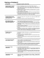
Having a Problem?
SITUATION
PROBABLE
OPENER
DOESN'T
OPERATE
FROM EITHER WALL PUSH
SUTTON OR TRANSMITTER
1. Have you disengaged all door locks? Review Step 8, Page 14
2. Does the opener have electric power? Plug a lamp into the outleL If it
doesn't light, check fuse box or circuit breaker (Some outlets are controlled by a wall switch).
3. Repeated operation may have tripped the overload protector in the motor.
Wait 15 minutes Try again
4. Is there a build-up of ice or snow under door? Door may be frozen to
ground. Remove any obstruction
5. Remove bellwire from opener terminal& Touch red and white screw terminals together with a jumper wire If opener runs, check for a faulty wire
connection at wall push button or a short under staples.
OPENER
OPERATES
FROM
TRANSMITTER
BUT NOT FROM
WALL PUSH BUTTON
1. Is wall push
procedure.
DOOR OPERATES
FROM
WALL PUSH BUTTON BUT NOT
FROM THE TRANSMITTER
2_ Are wiring
CAUSE
button
connections
& SOLUTION
lit? If not, refer
correct?
to No. 5 above
and follow
same
Review Step 6, Pg,13.
1 Does the battery test light glow when transmitter push button is pressed?
If not, replace the battery (Page 5 tells you how.)
2 If you have two transmitters and only one operates, review code setting
procedures on Page 1 9 Receiver and ALL transmitters must be set to
same code_
& Is transmitter(s) operating additional remote control devices? See code
setting procedures on Page 1 9
4. Did you press transmitter button designated to operate garage door
opener?
5 Re-program receiver(s) and ALL transmitters, Try setting ALL the code
switches in plus, center or minus positions. If transmitter(s) works, you
can try a random code switch setting again, if you desire.
TRANSMITTER
SHORT RANGE
HAS
1_ Check battery test light If the light is out, change
you how).
2. Change the location of transmitter
in the car.
3 A metal garage door, foil-backed
transmission
range.
4. Check to be sure the antenna
fully downward.
insulation
the battery(Page
or metal siding
5 tells
will reduce
on the back panel of the opener
extends
THE GARAGEDOOROPENS
AND CLOSES
SYITSELF
1 Is there a neighborwith a garage door opener using the same frequency
code? Change your code Review Page 19.
2. Check to makesure that the transmitter push button(s) is not stuckin the
'down' position
3. Remove bell wire from opener terminals and operate from transmitter
only If this solves the problem, the wall push button is faulty (replace), or
there is a short or broken wire between push button and opener
DOOR DOESN'TOPEN
COMPLETE_
1. Is something
obstructing
the door?
2. If door opens at least 5 feet, travel limits may need to be increased
turn equals 2 inches of travel See Pg 17. Repeat Safety Reverse
after adjustment
is complete
One
Test
3. If door has been working properly but now doesn't open all the way,
increase UP FORCE See Pg. 17 Repeat Safety Reverse Test after adjustment is complete
DOOR DOESN'T
COMPLETELY
CLOSE
1.
Review the Travel Limits Adjustment Chart on Page 17. Repeat Safety
Reverse Test after any adjustment of door arm length, close force or
down limit.
2o
Having a Problem? (Continued)
PROBABLE
SITUATION
i
CAUSE
,i I
& SOLUTION
i,ii ....
iiI
DOOR WON'T CLOSE
1
The infrared Reversing Sensor (if you have instaIJed this accessory}
may
be misaligned
or obstructed.
Disconnect
sensor and check door operation If problem disappears, correct alignment
DOOR REVERSES
FOR
NO APPARENT
REASON
1
Is something
obstructing
the door? Pull red emergency
release handle
Operate door manually If it is unbalanced
or binding, call a garage door
serviceman
to correct the problem
2
Clear any ice or snow from garage floor area where
3
Review the Force Adjustment
Chart on Page 17 Repeat
Test after adjustment
is complete
4.
If door reverses in FULLY CLOSED position, decrease travel limits (See
Pg 17) and repeat Safety Reverse Test after adjustment
is complete.
THE NEED FOR OCCASIONAL ADJUSTMENT OF FORCE AND LIMIT SETTINGS IS NORMAL. WEATHER CONDITIONS IN PARTICULAR CAN AFFECT
DOOR TRAVEL
5_
The Infrared Reversing Sensor(if you have installed this accessory) may
be misaligned
or obstructed.
Disconnect
sensor and check door operation. If problem disappears, correct alignment
OPENER
garage
door closes.
Safety
Reverse
DOESN'T TURN ON
1
Replace the light bulb (75Watts Maximum)
Use rough service bulbs if
standard bulbs burn out prematurely
due to vibration
(Vibration may be
caused by loose end panels_ Retighten screws)
DOESN'T TURN OFF
1
There may be a defective ground at ceiling or wall receptacle
Unit must
be grounded.
LIGHT
OPENER STRAINS OR
MAXIMUM
FORCE IS NEEDED
TO OPERATE DOOR
Door may be out of balance Use emergency
release rope and handle to
disconnect
trolley Open and close door manually.
A properly balanced door will remain in any point of travel while being supported e ntirely by its springs If it does not, call a garage door serviceman to
correct problem
OPENER
BRIEFLY,
Trolley may be ja mined into rail stop bo_ts Pull or push on door while motor
is hu taming to release jammed condition
Re-adjust door limits (Page 17)
to prevent over-traveL
MOTOR HUMS
THEN WON'T RUN
OPENER WON'T
DUE TO POWER
CHAIN
DROOPS
OPERATE
FAILURE
OR SAGS
2
if problem occurs on the first operation during the installation
process or
after the chain was removed and re-installed,
the motor may be out of
phase Remove chain; cycle motor to down position
(Observe the drive
sprocket When it turns in clockwise direction and stops, motor is in down
position) Re-install chain_
1
Use emergency release rope and handle to disconnect trolley Door can
be opened and closed manually When the power is restored, press the
wall push button and trolley wilt automatically reconnect
2
The emergency release key lock accessory (for use on garages with no
service door) disconnects the trolley from outside the garage in case of
power failure
It is normal for the chain to droop slightly in closed door position
Use
emergency release rope and handle to disconnect
trolley If chain returns
to normal height when trolley is disengaged
and door re_verses on a oneinch obstruction,
no adjustments
are needed See Page 9
21
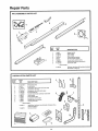
Repair Parts
RAI L ASSEMBLY
PARTS LIST
KEY
NO.
1
2
3
4
5
6
7
8
I
PART
NO.
DESCRIPTION
1A995
41 B2617
41 B2771
12A197
2B313
183B93
4182616
41 C2735
Master link kit
Outer trolley
Inner trolley
Chain retainer bracket
Tee ratFcenter section
Tee raiFend section (each)
Cable pulley bracket assy (each)
Chain and cable
NOT SHOWN
41A2814
Rail assy
iflustrated
hardware kit (includes
on Page 3)
hardwar(
',"sTAL-L_,T,0"
PA41:sLisi:
........................................................................
i.o. NO. DESO,,PT,O, '
1
41 D2736-1
Wall control
5
76
41
A2828
2119A3223
Emergency
rope ands cotter
handle pln
assy
H-e_dandrb_Wlrplu
a nd clevis
8
11_374
DD°°rr brr:Ckk:tt plate
l i iiiiis !;iii!=iiii'!s, °r
!
UL)
6
_
41A2815
Installation
hardware
_i"
bag (includes
hardware
22
illus-
,,,11!
_
/
"_
,_ tg%OO,,HO3O_gingbrooko,s .
i
_1 H
3 \I\
assy
_._ _Xi
III
ill
ll!l
"-_ -.IliL1
,
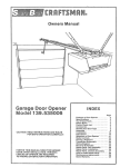
Repair
Chassis
Parts
Assembly
Parts List
6
21
18
7
3
16
11
15'
14
12
KEY
NO.
PART
NO.
DESCRIPTION
31 C290
41 A2627
Sprocket
cover
Gear and sprocket
assy
Complete
with:
Spring washer
Thrust washer
Retaining ring
Bearing
plate
Roll pins (2)
Drive gear
Worm gear
Helical gear w/retainer
Grease
Drlve/worm
gear kit w/grease
Roll pins (2)
Line cord
End panel
Light socket
Lens
Capacitor1/3h p
Capacitor1/2hp
Capacitor
bracket
3
41 A2817
4
5
6
7
6
41 B2991
41 A3076
175B88
108D30-1
30B387
3OB363
12A373
I
KEY
PART
NO.
NO.
DESCRIPTION
10
11
12
41A3150
41 A2821
41 D2748-2
13
14
15
16
17
18
19
20
41 D2748
41A2516
41D3013
41 C3005
41 C2726
41 A3027
41 A2826
41A2622
41 A3066
Terminal block w/screws
Universal replacement
motor
CoverModel 139,53413
& Model 13953606
CoverModel 139.53403
Helical gear & retainer w/grease
Limit switch assembly
RPM sensor assembly
Wire harness assy with plug
Motor bracket and bearing assy
Shaft bearing kit
Interrupter
cup assy.
Receiver
logic board assy
Complete
with:
Logic board
End panel w/all labels
End panel w/all labels
21
23
41 A3076
NOT SHOWN
41A2825
Chassis assy hardware
kit (includes
screws
not designated
by number in illustration)
I
S=FiA! S/ i;
Owners
Garage
Door
Manual
HOW TO ORDER
REPAIR
PARTS
Now that you have purchased your Sears Garage Door Opener, should
you ever need repair parts or service, simply contact any Sears Service
Center and most Sears, Roebuck and Co stores Be sure to provide all
pertinent facts when you call or visit,
Opener
Models:
139.53403
139o5341 3
139=53606
139o5361 0
The MODEL NUMBER of your garage door opener is printed on a label
located on the front panel of the opener chassis.
All parts listed may be ordered from any service center and most Sears
stores.
WHEN ORDERING
ING INFORMATION:
REPAIR
PARTS, ALWAYS
O PART NUMBER
O MODEL NUMBER
GIVE THE
FOLLOW-
@ PART DESCRIPTION
@ NAME OF ITEM
If the parts you need are not stocked locally, your order will be electronically transmitted to a Sears Repair Parts Distribution Center for
handling.
IMPORTANT
your nearest
NOTE: If you suspect radio control
SEARS Service Center
malfunction,
contact
MAINTENANCE
AGREEMENTS
... YOUR WAY TO BUY TOMORROW'S
SERVICE
AT TODAY'S
PRICE ... With nationwide service and the benefits of a Sears warranty plus a Sears Maintenance
Agreement,
you
The Maintenance
external
causes
To Purchase
don't
have
to worry
about
Agreement
such
does not cover
as: acts of abuse, fire,
a Sears
Maintenance
0
U
costly
repairs
installation
resulting
flood, wind, lightning,
Agreement
from
normal
- Ask
Any
of the
freezing, etc.
Salesperson
use.
product or damage resulting
or re-installation
or Call
Sears
Service
from
Today,
SEARS WARRANTY
FULL 90 DAY WARRANTY
For 90 days from the date
material or workmanship_
of purchase,
Sears
ON GARAGE
will repair
this
Garage
DOOR OPENER
Door Opener,
free of charge,
if defective
in
LIMITED
WARRANTY
From the 91st day until one year from the date of purchase, Sears will furnish replacement parts for any defective parts,
free of charge You pay for labor
LIMITED
1/2hpMotor:
replacement
WARRANTY
ON
1/2
HP
AND
1/3
HP
MOTORS
FOR
CRAFTSMAN
1/3hp Motor:
After1 yearandthrough3
years, ifthemotoronthisGarageDoorOpenerisdefective,
replacement
motor, free of charge. You pay for labor
0
0
D
D
OPENERS
After1 yearandthr_Ugh5years_ifthem_t_r_nthisGarageD__r_penerisdefe_tive'Searswi_lfurni_ha
motor, free of charge You pay for labor
Searswillfurnisha
LIMITATION
ON LIABILITY
Sears will not be liable for loss or damage to property or any incidental or consequential
expense
from
property
damage
due
directly
Some states do not allow the exclusion or limitation
exclusion may not apply to you
or indirectly
of incidental
from
the
use of this
or consequential
damages,
loss or
product,
so the above limitation or
This warranty does not cover repairs necessary because of operator abuse or negligence, including the failure to install,
adjust and operate this garage door opener according
to the instructions contained in the owner's manual
WARRANTY SERVICE IS AVAILABLE BY SIMPLY CONTACTING
THE NEAREST SEARS SERVICE CENTER/DEPARTMENT IN THE UNITED STATES This warranty applies only while the product is in use in the United States.
This warranty gives you specific legs] rights, and you may also have other rights which vary from state to state
SEARS
ROEBUCK
AND CO,, Dept,
698/731A
Sears Tower,
Chicago,
I L 60684
© 1987, Sears, Roebuck and Company
All Rights Reserved
114A976B
0
D
Q
Printed
in Mexico
0
D
N
0