1
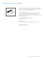
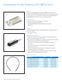
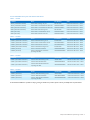
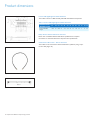
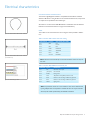
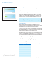
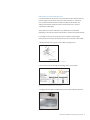
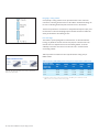
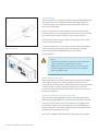
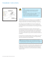
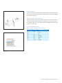
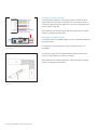
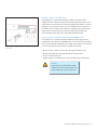
Design-in guide Fortimo LED High Brightness Module (HBMt) Gen3 Contents Introduction to this guide Information and support 4 4 Introduction to the Fortimo LED HBMt Gen3 Applications Product description Classification Product range Fortimo LED HBMt Gen3 system NA Xitanium LED drivers 4 4 4 4 4 Performance specification Module drive current, power and thermal specifications Module performance specifications Xitanium Programmable LED driver specification 6 7 Lighting characteristics Light distribution Universal mounting positions Optical files Spectral light distribution Color consistency (SDCM) Starting characteristics Lifetime characteristics Specified lifetime performance Flexible lumen package 8 8 8 8 8 8 8 8 9 9 Product dimensions Fortimo LED HBMt Gen3 dimensions Xitanium LED driver dimensions Cable Fortimo 7PA to 6wire – 600 mm dimensions 10 10 10 Electrical characteristics Connection between module and driver Fortimo LED HBMt Gen3 connector pins 11 11 11 Important recommendations and warnings 12 Controllability Default dimming protocols Constant Light Output Controlling Fortimo LED HBMt Gen3 with Xitanium LED drivers Which Philips controls can be used? 2 Philips Fortimo HBMt Gen 3 System Design In Guide Thermal management Temperature definitions Module temperature Temperature measurements Examples of standard heat sinks Heat sink material Thermal radiation and emissivity coefficient Thermal interfacing Xitanium LED driver temperature How to maximize system lifetime? Important points for luminaire design 15 15 15 18 18 21 21 22 22 23 23 Installation instructions Electrostatic device (ESD) measures Mechanical fixation Fixation of the driver Connection between module and driver Connecting one module to one driver Connecting two modules to one driver Replacing a module in a 2-module system Using a long cable in combination with the Fortimo LED HBMt system 24 24 24 25 25 26 26 27 Quality Compliance and approval marks Sustainability Conditions of acceptance IP rating, humidity and condensation Electromagnetic compatibility (EMC) Electrostatic discharge (ESD) Remote system operation Use of circuit breakers: Xitanium LED drivers Cautions on use during storage, transportation and operation System disposal 28 28 28 28 28 28 28 29 29 Zhaga Book 4: Flat emitter streetlight module Zhaga Luminance properties 1-10V Interface 31 31 31 33 13 13 13 Index of figures 34 Index of tables 35 14 14 Contact details Philips Fortimo LED HBMt Gen3 Partners for thermal interface materials 35 35 35 5 6 7 10 27 29 30 Introduction to this guide Thank you for choosing the Philips Fortimo LED High Brightness Module (HBMt) Gen 3 System. In this guide you will find the information required to design this module into a luminaire, including valuable hints and tips. Figure 1. Philips Fortimo LED high brightness module (HBMt) Gen3 system Information and support On our website http://www.philips.com/ledsystemsna you will find not only information about this module but also design-in guide and CAD files for the Xitanium drivers. If you require any further information or support please consult your local Philips office or visit: Fortimo LED HBMt product details and CAD files www.philips.com/leddrivers Xitanium drivers http://www.usa.lighting.philips.com/connect/LED_modules/led_drivers.wpd General information for OEMs www.philips.com/ledmodulesna Philips Fortimo HBMt Gen 3 System Design In Guide 3 Introduction to the Fortimo LED HBMt Gen3 Applications Philips Fortimo LED High Brightness Module (HBMt) Gen 3 System has been primarily developed for outdoor applications but can also be used indoors. The 3rd generation offers a drop-in replacement of Philips Fortimo LED High Brightness Module (HBMt) Gen 2 System on mechanics, optics and electrics. Product description To operate a system the following products are needed: • Fortimo LED High Brightness Module • Compatible Philips Advance Xitanium LED Driver, see Table 2 • Cable 60 cm Classification Figure 2. Fortimo LED HBMt Gen3 6000 lumen Figure 3. Xitanium 150W driver The Fortimo LED High Brightness Module (HBMt) Gen 3 System with Xitanium driver can be used in: • Non-Class 2, UL system IMPORTANT USAGE NOTES • Minimum drive current = 100 mA. If dimmed below 100 mA, Philips does not guarantee the specified product performance • Maximum drive current depends on the specific module (please refer to Table 6). This limit must be observed in all cases, including CLO • Tcase must not exceed stated maximum for the application, regardless of drive current • ∆ (Tcase -Tmax.ambient) must not stated maximum for the application, regardless of drive current • The correct values of Tcase and ∆T (Tcase -Tmax.ambient) are specified according the application (outdoor/indoor) • Failure to comply with usage conditions will void product warranty and will negatively impact product lifetime and performance Table 1. Product range Figure 4. Cable Fortimo 7PA to 6wire - 60 mm 4 Philips Fortimo HBMt Gen 3 System Design In Guide Product Name 12NC EOC Fortimo LED HBMt 4000/740 33W Gen3 929000882806 871829174461000 Fortimo LED HBMt 4000/757 33W Gen3 929000882606 871829174467200 Fortimo LED HBMt 4000/840 34W Gen3 929000882406 871829174477100 Fortimo LED HBMt 6000/740 49W Gen3 929000882706 871829174463400 Fortimo LED HBMt 6000/757 49W Gen3 929000882506 871829174475700 Fortimo LED HBMt 6000/840 51W Gen3 929000882306 871829174483200 Cable Fortimo 7PA to 6wire - 600mm 929000803903 871829121412000 Fortimo LED HBMt Gen3 system with Xitanium LED drivers Table 2. 1 module 1 Module Driver Part Number Cable 4000 lm (all CCT/CRI combinations) Xitanium 40W 0.53A Prog+ GL-J sXt 9290 007 10303 Cable Fortimo 7PA to 6wire – 600mm 4000 lm (all CCT/CRI combinations) Xitanium 75W 0.1A-0.7A AOCM 0-10V INT-Y sXT XI075C070V105DNY1 Cable Fortimo 7PA to 6wire – 600mm 6000lm (all CCT/CRI combinations) Xitanium 75W 0.1A-0.7A AOCM 0-10V INT-Y sXT XI075C070V105DNY1 Cable Fortimo 7PA to 6wire – 600mm 6000lm (all CCT/CRI combinations) Xitanium 75W 0.35A-0.7A Prog GL sXt 9290 007 02302 Cable Fortimo 7PA to 6wire – 600mm 6000lm (740 and 757) Xitanium 75W 0.1A-0.53A AOCM 0-10V sXt XI075C053V140DNY1 Cable Fortimo 7PA to 6wire – 600mm 6000lm (740 and 757) Xitanium 75W 0.53A INT-Y 0-10V sXT XI075C053V140CNY1 Cable Fortimo 7PA to 6wire – 600mm 2 Modules Driver Part Number Cable 2x 4000 lm (all CCT/CRI combinations) Xitanium 75W 0.35A-0.7A Prog GL sXt 9290 007 02302 Cable Fortimo 7PA to 6wire – 600mm 2x 4000 lm (all CCT/CRI combinations) Xitanium 75W 0.1A-0.53A AOCM 0-10V sXt XI075C053V140DNY1 Cable Fortimo 7PA to 6wire – 600mm 2x 4000 lm (all CCT/CRI combinations) Xitanium 75W 0.53A INT-Y 0-10V sXT XI075C053V140CNY1 Cable Fortimo 7PA to 6wire – 600mm 2x 6000lm (all CCT/CRI combinations) Xitanium 150W 0.53A-0.7A Prog GL sXt 9290 007 02202 Cable Fortimo 7PA to 6wire – 600mm 2x 6000lm (740 and 757) Xitanium 150W 0.53A Isolated Dim LEDINTA0530C280DO Cable Fortimo 7PA to 6wire – 600mm 2x 6000lm (740 and 757) Xitanium 150W 0.53A Non-Isolated Dim Input Voltage 347~480V LEDHCNA0530C280DN Cable Fortimo 7PA to 6wire – 600mm 3 Modules Driver Part Number Cable 3x 4000 lm (all CCT/CRI combinations) Xitanium 150W 0.53A-0.7A Prog GL sXt 9290 007 02202 Cable Fortimo 7PA to 6wire – 600mm 3x 4000 lm (all CCT/CRI combinations) Xitanium 150W 0.53A Isolated Dim LEDINTA0530C280DO Cable Fortimo 7PA to 6wire – 600mm 3x 4000 lm (all CCT/CRI combinations) Xitanium 150W 0.53A Non-Isolated Dim Input Voltage 347~480V LEDHCNA0530C280DN Cable Fortimo 7PA to 6wire – 600mm 4 Modules Driver Part Number Cable 4x 4000 lm (740 and 757) Xitanium 150W 0.53A-0.7A Prog GL sXt 9290 007 02202 Cable Fortimo 7PA to 6wire – 600mm 4x 4000 lm (740 and 757) Xitanium 150W 0.53A Isolated Dim LEDINTA0530C280DO Cable Fortimo 7PA to 6wire – 600mm 4x 4000 lm (740 and 757) Xitanium 150W 0.53A Non-Isolated Dim Input Voltage 347~480V LEDHCNA0530C280DN Cable Fortimo 7PA to 6wire – 600mm Table 3. 2 modules Table 4. 3 modules Table 5. 4 modules As the Xitanium LED driver portfolio is always growing to include new products, please contact your Philips sales representatives. Philips Fortimo HBMt Gen 3 System Design In Guide 5 Performance specification Module drive current, power and thermal specifications The following paragraphs contain the performance specifications of the Fortimo LED High Brightness Module (HBMt) Gen 3 System. Note: • All product performances are specified at Tcase= 85° C • ±10% tolerance applies to lumen specifications • Philips maintains a tolerance ±6.5% on luminous flux measurements. • Specifications are complaint with Zhaga Book 4 2 Table 6. Output current, power and thermal specifications 1 Module Rset drive current, (mA) Pmax @Rset Pthermal max@Rset Pmax drive current (mA) Pmax@max drive current Pthermal max@max drive current Fortimo LED HBMt 4000/740 33W Gen3 530 35 22 550 36 23.5 Fortimo LED HBMt 4000/757 33W Gen3 530 35 22 550 36 23.5 Fortimo LED HBMt 4000/840 34W Gen3 530 36 23 550 37.5 24.5 Fortimo LED HBMt 6000/740 49W Gen3 530 53 33.5 550 55 35 Fortimo LED HBMt 6000/757 49W Gen3 530 53 32.5 550 55 35 Fortimo LED HBMt 6000/840 51W Gen3 550 55 35 550 55 35 Warnings • Driving the module above stated maximum drive current voids product warranty and may have negatively affect product performance or lifetime • Driving the module above stated maximum drive may negatively • affect product performance and lifetime • Tcase and ∆T limits as specified in the Thermal management section must be observed for all drive currents 1. Specifications are subject to change, for the latest specifications please contact your local Philips Sales Representative 2. Go to www.zhagastandard.org 6 Philips Fortimo HBMt Gen 3 System Design In Guide Module performance specifications Fortimo LED HBMt Gen3 4000 lumen Table 7. Fortimo LED HBMt Gen3 specifications 4000 lumen Specification 4000/740 4000/757 4000/840 Unit Flux 4000 4000 4000 Lm Drive current 530 530 530 mA CCT 70 70 80 K Color consistency <7(1/4 ANSI) <7(1/4 ANSI) <7(1/4 ANSI) SDCM Tcase 85 85 85 ˚C Lifetime @Tcase 90%survivals 50,000 50,000 50,000 Hrs Light-emitting surface (LES) 60x15 60x15 60x15 Mm Current pins 7 7 7 - Current setting Rset1 or Rset2 Rset1 or Rset2 Rset1 or Rset2 - Approbation CE, ENEC, cUЯus CE, ENEC, cUЯus CE, ENEC, cUЯus - Table 8. Performance specifications Fortimo LED HBMt Gen3 4000 lumen Product Luminous fFlux, min (lm) Luminous flux, typical (lm) Luminous flux, max (lm) Efficacy, typical (lm/W) Power, typical (W) Power, max (W) Thermal power, typical (W) Max Input, Voltage (V) 4000/740 33W 3600 4050 4400 125 32.5 35 20 66 4000/757 33W 3600 4150 4400 128 32.5 35 19 66 4000/840 34W 3600 4050 4400 119 34 36 21 68 Table 9. Fortimo LED HBMt Gen3 specifications 6000 lumen Specification 4000/740 4000/757 4000/840 Unit Flux 6000 6000 6000 Lm Drive current 530 530 550 mA CCT 70 70 80 K Color consistency <7(1/4 ANSI) <7(1/4 ANSI) <7(1/4 ANSI) SDCM Tcase 85 85 85 ˚C Lifetime @Tcase 90%survivals 50,000 50,000 50,000 Hrs Light-emitting surface (LES) 60x15 60x15 60x15 Mm Current pins 7 7 7 - Current setting Rset1 or Rset2 Rset1 or Rset2 Rset1 or Rset2 - Approbation CE, ENEC, cUЯus CE, ENEC, cUЯus CE, ENEC, cUЯus - Table 10. Performance specifications Fortimo LED HBMt Gen3 6000 lumen Product Luminous fFlux, min (lm) Luminous flux, typical (lm) Luminous flux, max (lm) Efficacy, typical (lm/W) Power, typical (W) Power, max (W) Thermal power, typical (W) Max Input, Voltage (V) 6000/740 49W 5400 6100 6600 124 49 53 30 100 6000/757 49W 5400 6200 6600 127 49 53 29 100 6000/840 51W 5400 6000 6600 118 51 55 32 100 Xitanium Programmable LED driver specification For the latest Xitanium Programmable LED driver specifications, please refer to the individual product datasheet or the portfolio leaflet on www.philips.com/ledsystemsna. Philips Fortimo HBMt Gen 3 System Design In Guide 7 Lighting characteristics Light distribution The Fortimo LED High Brightness Module (HBMt) Gen 3 System provides lambertian light distribution, making it suitable for a variety of applications, e.g. street lighting, area lighting, urban lighting and architectural flood lighting. The light distribution can be best controlled using a specular/near-specular reflector. Universal mounting position The mounting direction of the Fortimo LED module is universal. For applications where a narrow batwing-like distribution is required, we recommend the modules be used in pairs to make optimal use of the module beam. Optical files Optical files in IES format, including Ray-sets, can be downloaded from the Fortimo LED HBMt webpage (http://www.lighting.philips.com/us_en/connect/ LED_modules/fortimo-HBMt.wpd). Figure 5. Polar diagram Fortimo LED HBMt Gen3 The photometric files can be used to check the system’s far-field intensity distribution. The initial reflector or luminaire design can be carried out using a lambertian emitter to gain simulation speed. The final design should always be verified using a simulation executed with a Ray-set for the module. Spectral light distribution Color consistency (SDCM) The target specification of the Fortimo LED HBMt Gen3 System for color consistency is within ANSI C78.377. This specification is similar to that of conventional discharge lamps used in outdoor lighting. The ANSI C78.377 has an approximate value of 7 SDCM, or Standard Deviation of Color Matching. This value refers to the size of an ellipse around the black body locus. Figure 6. Spectral light distribution for the Fortimo LED HBMt Gen3 Starting characteristics After ignition or re-ignition of the driver the module will immediately produce the intended amount of light. 0.BBL 4000K 5700K Lifetime characteristics Fortimo LED HBMt Gen3 System has expected lifetime of 50,000 oeprating hours with 90% survivals. Table 17 provides typical lumen output at end of life. Table 11. Fortimo LED HBMt Gen3 lumen maintenance Figure 7. Color consistency (¼ ANSI) Figure 7 shows color targets for the different color temperatures of the Fortimo LED HBMt Gen3. These are specified in the operating conditions Tc = 85° C, ∆T (Tcase-Tmax.amb≤50˚ C). In the application a color shift is possible if the case temperature is significantly different than specified. 8 Philips Fortimo HBMt Gen 3 System Design In Guide Product name (all CRI/CCt combinations) Initial lumen output (lm) Typical lumen output @50K hours (lm) Fortimo LED HBMt Gen3 4000 lm 4000 3400 Fortimo LED HBMt Gen3 6000 lm 6000 5100 Note: Lifetime performance specifications are based on 1 switching cycle per day and 4,000 burn hours per year, as conditioned for warranty. Operating the modules under deviating conditions may result in different lifetime, lumen maintenance or survival rates. Specified lifetime performance Figure 8 shows the expected lumen maintenance during a product lifetime. B50L70 indicates the minimum expected lumen maintenance level. Flexible lumen package LED drive current required to achieve the specified lumen package is specified in Table 6. In a system with Xitanium Programmable LED drivers, it is possible to Figure 8. Fortimo LED HBMt Gen3 lumen maintenance, Tcase = 85° C and T (Tcase-Tmax.ambient) ≤50˚ C achieve a light output different from the stated lumen package. By programming the Adjustable Output Current (AOC) in a linear relationship to the stated module Rset current, different lumen packages can be achieved. Maximum LED drive current allowed for each module is stated in Table 6. Warnings • Programming AOC above the stated maximum LED drive current (refer to Table 6) for the module type voids product warranty and will negatively impact lifetime performance. Fortimo LED HBMt Gen3 Module - 4000 and 6000 lumen Operating the Fortimo LED HBMt Gen3 at lower than specified Tcase will increase both the lumen output and the efficacy of the module. Figure 10 shows the relative increase in performance. Figure 9. Fortimo LED HBMt Gen3 flux and efficacy vs. LED drive current, 4000 and 6000 lumen Figure 10. Fortimo LED HBMt Gen3 flux and efficacy vs. Tcase Philips Fortimo HBMt Gen 3 System Design In Guide 9 Product dimensions Fortimo LED High Brightness Module dimensions The module consists of a PCB assembly with LEDs and additional components. Table 12. Fortimo LED High Brighness Module dimensions Dimensions in mm (NOMINAL±0.2MM) A1 A2 A3 A4 A5 A6 B1 B2 B3 B4 C1 C2 D1 Fortimo LED HBMt, all types 107.8 30 58.8 70 41.4 13.5 46 36 14.5 6.2 4 8 3.3 Philips Advance Xitanium LED driver dimensions Please refer to individual Xitanium LED driver specifications for complete information on mechanical dimensions and performance specifications. Figure 11. Fortimo LED HBMt Gen3 module Figure 12. Cable Fortimo 7PA to 6wire - 600mm Figure 13. Cable Fortimo 7PA to 6wire - 600mm 10 Philips Fortimo HBMt Gen 3 System Design In Guide Cable Fortimo 7PA to 6wire – 600 mm dimensions The module can be connected to Xitanium LED drivers (Table 2-3) using a 7-pinto-wire cable (Figure 13). Electrical characteristics Connection between module and driver The Fortimo High Brightness Module is compatible with both Rset1 and Rset2 Xitanium LED drivers. Using the Rset on the module with these drives, will provide an output current specified for the module type. We advise to use the Fortimo LED HBMt Gen3 in combination with the Xitanium LED drivers mentioned in Tables 2 to 5 (approved combinations). Figure 14. Cable Fortimo 7PA to 6wire - 600 mm Cable The module can be connected to the driver using the cables specified in Tables 2 to 5. Table 13. Fortimo 7PA to 6wire cable color coding Figure 15. Cable Fortimo 7PA to 6wire - 600 mm (929000803903) Connector pin Function Color coding drive/cable Pin 1 LED+ Red Pin 2 - No wire Pin 3 LED- Blue Pin 4 RNTC Black/White Pin 5 Rset2 Yellow/Black Pin 6 Rset1 Yellow Pin 7 Common Blue/White Note: The Rset2 wire should be left unconnected when Rset1 drivers are used, and vice versa. Table 14. Fortimo LED HBMt Gen3 connector pins Figure 16. Cable wiring to driver Connector Signal Destribution Pin 1 IDC LED driver current input Pin 2 (HV spacer) Not connected Pin 3 PGND Power ground Pin 4 NTC Temperature sensor (RNTC) resistor in series Pin 5 Rset2 Resistor for current setting of LED driver type Rset2 Pin 6 Rset1 Resistor for current setting of LED driver type Rset1 Pin 7 SGND Signal ground Note: It is possible to connect two or more modules in series to one Xitanium driver by using multiple cables. It is important to note that the driver can only communicate with one of the modules (master/slave), see Installation instructions. Philips Fortimo HBMt Gen 3 System Design In Guide 11 Important recommendations and warnings The following recommendations and warnings should be taken into account when using Fortimo LED High Brightness Modules and Xitanium LED drivers. Important usage conditions • Minimum drive current = 100 mA. If dimmed below 100 mA, Philips does not guarantee product performance • Maximum drive current is defined in Table 6. This limit must be observed in all cases including CLO, or product warranty is voided. • Tcase, ∆T, must not exceed specified maximum for each usage case, regardless of drive current • Failure to comply with usage conditions will void product warranty Design-in phase • It is mandatory to design the luminaire in such a way that it can only be opened with special tools (by electricians) in order to prevent accidental contact with live parts • Safety and UL/CSA recommendations: the general UL/CSA recommendations for luminaire design and national safety regulations (NEC) also apply to selected Fortimo LED HBMt modules and Xitanium driver. Luminaire manufacturers are advised to conform to the safety standards for luminaire design (UL1598-Luminaires) • The luminaire must be constructed in such a way that the LED module cannot be touched by the end-user (safety) • Do not apply mains power directly to the LED module Design-in and manufacturing phase • Do not use damaged or defective modules • Do not touch LEDs.Take ESD precautions • Do not put extra force on the LED modules while screwing them in the luminaire (respect assembly prescription) • Do not drop the LED module or let any object fall on top of the module as this may damage the insulation layer of the LED board. Do not use the LED module if it has been dropped or an object has fallen on it and there are visible defects or damage Installation and service phase of luminaires • The luminaire should not be serviced when the mains voltage is connected; this includes connecting or disconnecting the cable. 12 Philips Fortimo HBMt Gen 3 System Design In Guide Controllability Default dimming protocols The Fortimo LED HBMt Gen3 module is dimmable with a range of integrated light control options. • Adjustable Output Current • Constant Light Output • 1-10 V, AmpDim, DALI and Dynadimmer dimming Specific features will depend on the Philips Advance LED driver system selected (Tables 2-3). Please visit www.philips.comledsystemsna for complete information on the integrated light control options available in the Xitanium product range. Note: Although it is technically possible to dim Fortimo LED HBMt Gen3 modules below 100mA, Philips does not specify product performance for modules operating Figure 17. Energy savings with CLO below this current. Constant Light Output There are minimum light level requirements for public lighting. In order to compensate for lumen depreciation, which occurs in all light sources over time, the lighting design is often over-lit at the beginning of the source’s lifetime. It is possible to deliver energy savings by avoiding over-lighting and still ensuring the minimum expected light level over the lifetime of the module if the Constant Light Output (CLO) feature in Xitanium Programmable drivers is used. The CLO feature uses a predictive algorithm to increase the output current to the module over the specified lifetime of 50,000 hours*. As the current increases, the energy consumption also increases. The CLO feature can be combined with other dimming protocols for even greater energy savings. Programming CLO in Fortimo LED High Brightness Module Gen 3 will ensure minimal light levels without wasting energy in the beginning of module’s life. Please use Table 15 to program the CLO curve for Fortimo LED HBMt Gen3. Table 15. Fortimo LED High Brightness Module CLO curve, all module types * Average rated life is based one engineering data testing and probability analysis. The hours are at the B50, L70 point - 50,000 hours life with 70% lumen maintenance at Tc point of 56°C for 3R and 61°C for 1R. Module working hours Power level 0 85% 4,000 86% 8,000 87% 12,000 89% 16,000 90% 20,000 91% 24,000 92% 28,000 93% 32,000 95% 36,000 96% 40,000 97% 50,00 100% Philips Fortimo HBMt Gen 3 System Design In Guide 13 Warning! • Using CLO will deliver the typical lumen output at end of module’s life, constant over the whole lifetime , not the specified initial lumen output of the module. For example, programming CLO with a Fortimo LED High Brightness Module 6000lm will provide a stable 5100lm over the expected life of the module, NOT 6000lm over the expected life of the module • Warranty will apply only when the CLO is programmed according to Table 15 Controlling Fortimo LED High Brightness Module with Xitanium LED drivers Xitanium LED drivers allow the use of several control protocols, including 1-10V, DALI, Integrated Dynadimmer and CLO. Fortimo LED HBMt modules can be used with both Rset1 and Rset2 LED drivers. Further details on programming can be found in the Design-in guide for Xitanium LED Programmable Drivers. The Design-in guide can be downloaded via our website at www.philips.com/ledsystemsna. Which Philips controls can be used? Further information about our entire portfolio of control products is available at http://www.lighting.philips.com/us_en/connect/controls/index.wpd. 14 Philips Fortimo HBMt Gen 3 System Design In Guide Thermal management The critical thermal management points for the module and driver are set out in this chapter in order to facilitate the design-in of the Fortimo LED HBMt Gen3. Keeping these thermal points in mind will help to ensure the optimal performance and lifetime of the system. Table 16. Thermal definitions Item Description Symbol Unit Ambient temperature Temperature of the air surrounding the luminaire in the test environment or application Tamb °C Maximum rated luminaire ambient temperature Maximum rated luminaire temperature of the air surrounding the luminaire in the application Tmax.amb °C Case temperature The representative temperature of a module or driver, defined at a specific position on the module or driver Tcase °C Module temperature The temperature measured at the specified Tcase position on the module - °C Driver temperature The temperature measured at the specified Tcase position on the driver - °C Delta T The maximum temperature difference between Tcase and Tmax.amb ∆T °C Note: In order to ensure accurate Tcase test results, the case temperature should not vary by more than 1° C for a period of at least 30 minutes after a stable temperature has been achieved. Module temperature To achieve typical product lifetime characteristics, it is critical to ensure that the product is operating within specified temperature limits. These limits depend on both the product and the application, including luminaire design and maximum rated luminaire ambient temperature. Philips Fortimo HBMt Gen 3 System Design In Guide 15 Thermal specifications To ensure the optimal performance and life time of the system. The following conditions have to meet: • Maximum Tcase ≤ 85° C at maximum rated luminaire ambient temperature • T (Tcase - Tmax. amb) ≤ 50° C (Maximum allowed difference between case and rated luminaire ambient temperature) Table 17. Determining maximum Tcase for an application Maximum rated luminaire ambient temperature Maximum 40˚ C 45˚ C 85˚ C 55˚ C 30˚ C 85˚ C 30˚ C 50˚ C 80˚ C ∆T (Tcase –Tamb) Maximum Tcase Outdoor applications, Tmax.amb = 40° C When the maximum outdoor ambient (Tmax.amb) is 40° C, the luminaire design needs to ensure that • Module temperature does not exceed 85° C when tested in a lab environment at 40° C ambient • ∆T must not exceed 45° C Indoor applications, Tmax.amb = 30° C When the maximum indoor ambient (Tmax.amb) is 30° C, the luminaire design needs to ensure that • Module temperature does not exceed 80° C when tested in a lab environment at 30 °C ambient • ∆T must never exceed 50° C High Bay or Industrial applications, Tmax.amb = 55 °C If the given luminaire operates under indoor conditions (e.g. high-bay or industrial application Tmax. amb is rated for 55° C), the luminaire design needs to ensure that • Module temperature does not exceed 85° C when tested in a lab environment at 55° C ambient • ∆T must never exceed 30° C 16 Philips Fortimo HBMt Gen 3 System Design In Guide Thermal de-rating The Fortimo High Brightness Module contains a thermal de-rating system to detect overheating and extreme lifetime degradation of the LEDs when operated outside the maximum permitted temperature conditions. Such conditions can be caused by extreme ambient conditions or inadequate heat management design. The thermal de-rating is based on temperature detection on the module. When multiple modules are connected to 1 driver, one module is in the “master” mode and the others are in the “slave” mode. It is strongly recommend that the module with the highest Tcase in the application is used as the “master” module. How does it work? The thermal de-rating system is a default feature in some Philips Advance Xitanium LED drivers. When the case temperature rises above the specified limit, the driver switches to a lower LED output current. When the case temperature drops below the specified limit, the system will resume normal operation. Warning! • MTP is only a failsafe in order to protect the module against overheating during peaks in ambient temperature or in the event of a faulty heat sink design. Optimum performance will only be achieved if the Tcase meets the thermal boundaries stated above and measured ccording to the procedure described below • MTP diagnostic feature cannot be used for Tcase measurements • Not all drivers have the thermal de-rating system, please refer to individual Xitanium LED driver specification Philips Fortimo HBMt Gen 3 System Design In Guide 17 When the module is used in combination with Xitanium LED drivers, the default driver profile will ensure the correct Module Temperature Protection (MTP) settings. The thermal de-rating feature will be triggered above a case temperature of 85° C. Note: The default MTP setting for Xitanium Programmable LED drivers is “Philips LED Light Engine”. This setting offers optimized profile for use with all Philips LED modules, including Fortimo LED HBMt, for maximum Tcase. For best system performance, we advise not changing the default profile or the dimming curve The Philips LED Light Engine profile is defined for module operated with a Figure 18. Temperature test point on bottom PCB Tcase=85° C. For use in applications where a lower Tcase must be reached, please contact your Philips representative for guidelines. Temperature measurements The maximum ambient temperature at which the luminaire will operate constitutes the initial key criterion for defining the correct temperature limit and validating the thermal luminaire design. Example for outdoor applications: If the desired maximum operating ambient temperature is 40° C or lower, the luminaire design needs to ensure that the module temperature does not exceed 85° C when tested in a lab environment at 40° C ambient. For indoor applications, the luminaire design needs to ensure that the module temperature does not exceed 85° C and meet a maximum ∆T between the module and ambient of ≤ 50° C. If the desired maximum operating ambient temperature is 25° C or lower, the luminaire design needs to ensure that the module temperature does not exceed 75° C when tested in a lab environment at 25° C ambient. Maximum ∆T meets 50° C. Note: The ambient temperatures are refering to the average ambient temperatures around the luminaire during the operational period of the module. Critical temperature point (Tcase) For LEDs, the junction temperature is the critical factor for operation. Since there is a direct relation between the case temperature and the LED junction temperature, it is sufficient to measure the aluminum casing of the Fortimo LED HBMt at its critical temperature point, see Figure 19. If the case temperature at the Tcase point exceeds the specified maximum Tcase, this will have an adverse effect on the performance of the LEDs and the Fortimo LED HBMt module in terms of light output, lifetime and lumen maintenance. 18 Philips Fortimo HBMt Gen 3 System Design In Guide Measurement of critical temperature point It is important that the Tcase point is free of thermal interface material when the thermo couple is connected for temperature measurements. It is essential to have a stable connection between the thermal couple and the module. Any shifting of the thermal couple will results in measurement errors and poor measurement repeatability. The temperature must be stable before any reliable data can be obtained (depending on the size and material of the luminaire, between 30 and 180 minutes). It is possible to measure the temperature in three different ways through a thermocouple connected to the indicated Tcase point on the back of the module. 1. Preferred method: Via a groove in the module mounting surface: Figure 19. Tcase measurement via thermocouple in a groove 2. Via an access point cut through the mounting surface of the module: pad pad pad Figure 20. Tcase measurement via an access point 3. 40 gauge Thermocouple in-bedded inside of the module’s aluminum substrate: 40 gauge Thermocouple Philips Fortimo HBMt Gen 3 System Design In Guide 19 Designing a cooling solution Conceptually a cooling solution can be represented with a series of thermal resistances, connecting the heat source to the ambient. Good thermal design can be seen as minimizing the thermal path from heat source to the ambient. The thermal performance of a luminaire is mainly determined by two major parts, the heat sink or main heat dissipating body and the thermal interface which will shortly be discussed in the following section. Figure 21. Thermal network Heat sink design The module is primarily designed for metal luminaires, in which the luminaire housing may double as the heat sink. The main purpose of the heat sink in the thermal chain is to dissipate heat into the surrounding ambient. To do this efficiently a heat sink’s main task is to increase the area in contact with the surrounding ambient. Table 18 provides an indication for the required effective cooling area per HBMt module. Table 18. Fortimo LED HBMt typical cooling surface requirements (x1000 mm2) Figure 22. AVC heat sinks which can be used in combination with Fortimo LED HBMt 3 Maximum rated luminaire ambient temperature (Tmax. amb) 4000ml /840 4000lm /740 4000lm /757 6000lm /840 6000lm /740 25˚ C 106-127 103-123 97-117 164-197 155-185 35˚ C 127-159 123-154 117-146 197-246 185-232 45˚ C 159-212 154-205 146-195 246-329 232-309 3. Suggested products which can be used with Fortimo LED HBMt systems. Reference to these products does not constitute endorsement by Philips. 20 Philips Fortimo HBMt Gen 3 System Design In Guide Heat sink material The type of material used has a significant influence on the final result. For example, a comparison of the thermal conductivity (k) of copper with that of corrosionresistant steel (see Table 19) shows that a substantially smaller heat sink can be made with copper. The best material for heat sink is (soft) aluminum. The thickness (H) of the heat sink is also of major importance. If identical heat sinks made from different materials were used, a similar effect would be achieved with 1 mm copper, 2 mm aluminum, 4 mm brass, 8 mm steel and 26 mm corrosion-resistant steel. Table 19. Thermal conductivity Material W/mK Copper 400 Aluminum 200 Brass 100 Steel 50 Corrosion-resistant steel 15 In summary a thermally more conductive material helps heat spreading over the body and activates more effective cooling area. Thermal radiation and emissivity coefficient Thermal radiation accounts for a substantial part of the total heat transfer. The amount of thermal radiation is highly dependent on the emissivity coefficient of the surface. For example, a polished aluminum surface has a very low emissivity coefficient, while a painted surface has a very high one. A higher emissivity coefficient means more effective heat transfer. Table 20. Thermal emissivity coefficients of common materials Material Finish Emissivity coefficient Aluminum New/polished 0.04-0.06 Blank 0.20-0.30 Anodized 0.80-0.95 New/polished 0.1 Painted/ coated 0.80-095 Steel Philips Fortimo HBMt Gen 3 System Design In Guide 21 Thermal interfacing The thermal interface is a critical item for design-in of Fortimo LED HBMt system. The module’s small area in combination with the relatively high thermal load translates into high power densities, which increase the impact of the thermal interface on the total system. The thermal interface is the interface between the module and the mounting surface in the luminaire. To ensure good thermal contact, the contact area should be covered with thermal interface material, e.g. thermal paste, Figure 23. Around 50 micron thickness of thermal paste, equality spread on the total flat surface of the heatsink is advised. Figure 23. Interface between module and mounting plate filled with thermal paste If the use of thermal paste is not appropriate, and some other thermal interface material is used (e.g. phase change, graphite, or thermal pad) it is strongly recommended to follow installation instructions for the selected interface materials. Warning! • The use of thermal interface materials other than thermal paste might require the use of higher efficiency heat sink • Applying excessive thermal paste does not result in improved thermal management. For best performance, it is essential to follow the guidelines above Figure 24. Label on the Xitanium driver indicates Tcase point Xitanium LED driver temperature The next key component is the driver, which influences the lifetime and reliability of the system. It is important to ensure good thermal and electrical contact between the driver and the luminaire as this enables the heat to dissipate efficiently and allows the driver to deliver optimal electrical performance. The driver temperature can be measured with a thermocouple at the Tcase point, shown on the driver label, Figure 24. Critical driver temperature point with respect to CLO When the Fortimo LED High Brightness Module is used with Philips Advance Xitanium Programmable LED drivers, usage of the CLO feature will increase the output current. As a result, the driver losses will increase accordingly, which in turn will lead to a higher driver Tcase temperature. For the thermal design it is therefore important to ensure that the Tcase temperature of the driver is within specification for its Tcase max at end of life. Please refer to individual product datasheets for Tcase information for lifetime. 22 Philips Fortimo HBMt Gen 3 System Design In Guide How to maximize system lifetime? • Ensure good thermal contact between module, driver and the coldest part of the luminaire • Place module(s) and driver at a distance from each other to obtain a more homogeneous temperature distribution in the luminaire • It is recommended that the modules are mounted on an aluminum housing that is at least 3 mm thick; thinner housings will limit the heat flow through the housing, while thicker housings will improve the heat flow through the luminaire, resulting in a lower Tcase of the module Important points for luminaire design • When multiple modules are used, it is recommended they are spread out in the luminaire, in order to distribute the thermal load • Reflectors should be used in the design of optics • In order to accommodate every application, Fortimo LED High Brightness Modules can be dimmed or used in pairs to optimize the lumen package • Simplify the heat path from modules to ambient air. Limit the number of thermal interfaces in the primary heat path towards the ambient air • If thermal interfaces are inevitable, use thermal interface materials (TIM) to ensure proper thermal contact, i.e. between module and luminaire housing • Ensure proper heat dissipation by using highly conductive materials and/ or materials of sufficient thickness to maximize effective use of the available cooling surface • Use anodized, painted surfaces rather than blank surfaces in order to increase the transfer of heat via thermal radiation Philips Fortimo HBMt Gen 3 System Design In Guide 23 Installation instructions Warning! The Fortimo LED HBMt Gen3 should always be replaced by a trained installer. Special attention should be paid to the following points: • Do not service the system when the mains voltage is connected; this includes connecting or disconnecting the cable • Before a new Fortimo LED HBMt is mounted, the old thermal interface must be removed and the area must be cleaned Figure 25. Fixation of the HBMt module Mechanical fixation The separate components (driver and module(s)) of the Fortimo LED HBMt Gen3 system can be fixed in place securely using the mounting holes located on the module(s) and driver. Please refer to the dimensional drawings for specific details. Before affixing the Fortimo LED HBMt Gen3, ensure that the mounting surface is clean and flat without any protrusions or pits. To ensure a reliable thermal and mechanical attachment, we recommend the flatness of the mounting surface should be ≤ 0.2 mm. For the best thermal performance use a thin layer of thermal paste (max 50 micron) between the module and the mounting surface. The entire bottom surface of the module needs to be covered with thermal paste, with a typical bond line of 30 to 50 microns. Other thermal interface materials can be used but will require more cooling from the luminaire (i.e. larger contact area between the luminaire and the ambient). Use 4 M3 fasteners for the brackets and apply a torque of 0.6 Nm ± 0.1 Nm. Screw the module on the luminaire/heatsink by fixating the screws in diagonal following order, this to spread the force over the total module. Note: When stainless steel fasteners are used in combination with an aluminum luminaire, depending on local conditions, galvanic corrosion between the metal parts can occur without preventative measures. It is strongly advised to use a wax or lubricant. If fasteners cannot be used or are not accessible, another mounting option is to use a spring clip for each bracket. The spring clip will press uniformly the bracket onto the LED module. In this situation, use the complete length of the pressed groove from the bracket for the clip. Press force for each clip on position of the bracket is 1000 Nm ± 100 Nm. 24 Philips Fortimo HBMt Gen 3 System Design In Guide Fixation of the driver The Xitanium driver has fixation holes on the short ends of the casing. The driver should be mounted securely on a flat area of the luminaire, using the mounting hole on each side of the driver. Connection between module and driver A cable is available to connect the module to the driver; the color coding of the cable wires has been aligned with the color coding of the driver wires to ensure easy installation. Figures 27 – 30 show the details of the HBMt cable and the colorcoded wires on the driver. Fortimo LED HBMt Gen3 wiring Table 21. Fortimo LED HBMt cable color coding Figure 26. Fixation of the Xitanium driver Connector pin Function Color coding driver/cable Pin 1 LED+ Red Pin 2 - No wire Pin 3 LED- Blue Pin 4 RNTC Black/White Pin 5 Rset2 Yellow/Black Pin 6 Rset1 Yellow Pin 7 Common Blue/White Figure 27. Fortimo LED HBMt Gen3 connector wiring towards LED driver Philips Fortimo HBMt Gen 3 System Design In Guide 25 Connecting one module to one driver A standard cable is available for connecting the module to a driver. The color coding of the wires in this cable corresponds to that in the Xitanium driver. If a set-up with a single module and a single driver is used, the corresponding colors need to simply be connected. The unused Rset wires should be clipped short and wrapped with an insulating material e.g. a fiberglass insulating sleeve. Connecting two modules to one driver It is possible to connect two HBMt modules in series to one Xitanium LED driver by using two cables. Figure 28. Wire color coding on Xitanium Programmable LED driver with Rset1 It is important to note that the driver can only communicate with one of the modules. This means that output current setting and Module Temperature Protection read-out are only available on one of the two modules. The unused Rset wires should be clipped short and wrapped with an insulating material e.g. a fiberglass insulating sleeve. Figure 29. Color coding (one module connected to one Rset1 driver) 26 Philips Fortimo HBMt Gen 3 System Design In Guide Replacing a module in a 2-module system Special attention is required when replacing a module in 2 modules/1 driver configuration. Due to the fact that the driver can only read out information from a single module, in case of failure we recommend replacing both modules, as current settings can vary from batch to batch over time as LED performance improves. If the installer does not replace both modules it is possible that one of the modules will be driven at the wrong current and will not produce the specified lumen output. Production date code on the module label identifies the batch. Using a long cable in combination with the Fortimo LED HBMt system It is possible to use a connection between module/s and driver longer than the standard 60cm cable. When using AWG24 cables, the connection can be extended up to 10 meters without affecting the power supply to the module. It is not advised Figure 30. Color coding (two modules connected to one Rset1 driver) to use the communication wires because of possible interferences. • • • • Do not use Rset - output current needs to be programmed in the driver Module Temperature Protection (RNTC) function cannot be used Do not use the Common wire Design-in support is available; please contact your Philips sales representative Warning! When using a long cable between module and driver, extra care should be taken in the design of EMI, surge and noise suppression Philips Fortimo HBMt Gen 3 System Design In Guide 27 Quality Compliance and approval marks The Philips Fortimo LED HBMt is UL and CSA approved and complies with the applicable EU directives. To ensure approval of the luminaire, the conditions of acceptance need to be fulfilled. Module-related data can be found in CSA 250-13 and UL8750. All luminaire manufacturers are advised to conform to the international standards of luminaire design (CSA 250-13 or UL1598). Sustainability Fortimo LED High Brightness Modules are compliant with European Directive 2011/65/EU, recasting 2002/95/EC on Restriction of the Use of Certain Hazardous Substances in Electrical and Electronic Equipment (RoHS). The modules comply with Reach, as defined by the EU Chemical Agency. Conditions of acceptance Details can be requested from your local sales representative. IP rating, humidity and condensation The Fortimo LED High Brightness Modules are build-in systems and therefore have no IP classification. They are not designed for operation in the open air. The OEM is responsible for proper IP classification and approbation of the luminaire. Warning! • The Fortimo LED HBMt has been developed and released for use in damp locations • Do not use in locations where condensation is present. • If there is a possibility that condensation could come into contact with the modules, the system/luminaire builder must take precautions to prevent this Electromagnetic compatibility (EMC) Electromagnetic compatibility, EMC, is the ability of a device or system to operate satisfactorily in its electromagnetic environment without causing unacceptable interference in practical situations. In general, LED modules have no effect on the EMC of a luminaire. The Fortimo LED HBMt was tested with a Xitanium driver in a reference luminaire and no EMC issues were observed. Introduction to Electrostatic discharge (ESD) It is generally recognized that Electro Static Discharge can damage electronic components, like LED chips, resulting in early failures. Professional users of electronic components are used to implementing extensive and rigorous measures to prevent ESD damage in their finished products. With the introduction of LED components for lighting, a new breed of users, such as OEMs and installers, are now involved in handling and using electronic LED components in the manufacturing process. 28 Philips Fortimo HBMt Gen 3 System Design In Guide ESD in the production environment Depending on the immunity level of the LED board, there is a minimum set of measures that have to be implemented when handling LED boards. ESD measures are required in a production environment where handling can exceed the ESD immunity level. Furthermore, products that are susceptible to ESD must be packed and delivered in ESD-safe packaging. The purpose of an effective ESD-control strategy is to reduce line failures, final inspection failures and field failures. ESD specifications Philips designed HBMt module Gen3 products to be robust when exposed to ESD. The maximum permitted contact discharge level and air discharge level, according to IEC 61000-4-2 (HBM 150pF + 330Ω), is 8 kV contact and 15 kV air. Servicing and installing luminaires It is highly recommended that installers are instructed not to touch the LED components and to use earthed arm straps to prevent ESD damage during installation and maintenance. ESD consultancy Independent ESD consultancy companies can advise and supply adequate tools and protection guidance. Remote system operation Please consult the design-in guide for Xitanium LED drivers. Use of circuit breakers: Xitanium LED drivers Please consult the design-in guide for Xitanium LED drivers at http://www.lighting.philips.com/us_en/connect/LED_modules/xitanium_ programmable.wpd Cautions on use during storage, transportation and operation • Store in a dark place • Do not expose to sunlight • Maintain temperature between -40 to +85° C • Relative humidity (RH) between 5 and 85% During operation Fortimo LED HBMt must be operated within the specifications found in the product datasheet and design-in guide. Please contact your local sales representative for additional information. Philips Fortimo HBMt Gen 3 System Design In Guide 29 System disposal We recommend that the Fortimo LED High Brightness Module and its components are disposed of in an appropriate way at the end of their (economic) lifetime. The modules are in effect normal pieces of electronic equipment containing components that are currently not considered to be harmful to the environment. We therefore recommend that these parts are disposed of as normal electronic waste, in accordance with all federal, state and local laws and regulations. 30 Philips Fortimo HBMt Gen 3 System Design In Guide Zhaga Book 4: Flat emitter streetlight module Zhaga Zhaga is a global consortium form by companies from across the lighting industry. The overriding aim is to bring standardization to applications in general lighting by creating welldefined interface specifications. This ensures the interchangeability of LED light sources from different manufacturers. All Fortimo LED high brightness module Gen2 (HBMt) products are Zhaga certified. For more information on Zhaga, please refer to the website: http://www.zhagastandard.org for complete details. Luminance properties The LED Module shall emit light of a Lambertian distribution in the direction perpendicular to the mechanical reference plane. The luminance distribution of the LLE is described by the following characteristics: Figure 31. Zhaga logo • • • • Vertical symmetry Horizontal symmetry Center balance Uniformity To enable a proper characterization of the luminance distribution, the LES is subdivided into 8 areas A1 to A8, in which average luminance is measured with an imaging luminance measuring device. Each of these areas covers one eighth of the whole LES. These areas allow the calculation of the above relevant uniformity factors without counting the single LEDs which may be placed in an arbitrary variety inside the light emitting surface. Luminance Uniformity Parameter U The uniformity parameter U is determined by first calculating the average and Root Mean Square (RMS) of the Luminance Lj of every pixel j inside the LES whereby N equals the number of pixels: Lavg= (∑ Lj) /N LRMS= √(∑ (Lj)2 ) /N) The uniformity parameter U is calculated as U = Lavg / LRMS Maximum total thermal power of the module Maximum thermal power generated by the LED module (unit: W). The maximum thermal power equals the maximum electrical power (unit: W) that is supplied to the LED module minus the minimum optical power (unit: W). The optical power (Pvis,unit: W) is the radiant flux of the LED module in the wavelength range from 380nm up to 780nm (unit: W). Philips Fortimo HBMt Gen 3 System Design In Guide 31 Maximum Thermal power @ thermal interface The LED Module generates an amount of heat which is represented by the max thermal Power as: Pth, max = Pth rear, max + Pth, front max The major portion (Pth, rear) is transferred via the Thermal Interface Surface by heat conduction. The Pth, front portion is transferred by means of IR radiation and convection in the direction of the light beam. Maximum Allowable Thermal resistance of the Luminaire Value of the thermal resistance from the Thermal Interface Surface to the environment for which holds: Tr=Tr,max (unit: K/W). This value is to be defined by the manufacturer as the temperature at which the Rated LED Module performance is specified. Tr=ta +Rth*Pth, rearwhere ta is the average temperature of the air in the vicinity of the Luminaire and Rth is the thermal resistance from the Thermal Interface Surface to the environment. Rated Operating Temperature Tr.max The Reference Temperature Tr is the temperature at the TIM-Heatsink interface of a LED module that is thermally connected to the heatsink with this TIM (unit: K). In practice this temperature is measured in the heatsink near the TIM-Heatsink interface. The case temperature Tcase is related to this reference temperature Tr as follows: Tcase = Tr + Rth TIM*Pth LED Module The Rated Operating Temperature, Tr,max, is the value of the Reference Temperature (Tr) at which the rated values are specified. Table 22. Zhaga luminous flux categories Flux category Luminous Flux [lm] Minimum Maximum C011 990 1,320 C025 2,250 3,000 C040 3,600 4,800 C060 5,400 7,200 C080 7,200 9,600 C100 9,000 12,000 Recommended Zhaga-compliant Xitanium LED drivers 32 Philips Fortimo HBMt Gen 3 System Design In Guide Product name ECG Zhaga Category System Safety Compliance Xitanium 40W 0.70A Prog+GL-J sXt DS2 Class I, II Xitanium 75W 0 7A AOCM 1-10V GL-Y sXt CL1 Class I, II Xitanium 75W 0.35-0.7A GL Prog sXt BL1 Class I, II Xitanium 150W 0.35-0.7A GL Prog sXt BL1 Class I, II Flat emitter streetlight module product specifications. Table 23. Zhaga Book 4 specifications Zhaga specification 4000lm 740 4000lm 757 4000lm 840 6000lm 740 6000lm 757 6000lm 840 Number of LED modules 1 1 1 1 1 1 Luminous Flux Category C040 C040 C040 C060 C060 C060 LES dimensions [mm] 58.80x14.5 58.80x14.5 58.80x14.5 58.80x14.5 58.80x14.5 58.80x14.5 LES category 3 3 3 3 3 3 Uniformity (UL) 0.336 0.324 0.338 0.403 0.407 0.41 Vertical Symmetry (SymmL,v) 0.961 0.985 0.991 0.971 0.967 0.98 Horizontal Symmetry (SymmL,h) 0.998 0.962 0.983 0.923 0.983 0.974 Center Balance (BalL,cent) 1 0.899 0.977 0.947 0.889 0.877 Correlated Color Temperature [K] 4000 5700 5700 4000 5700 5700 CRI value [Ra] CRI>70 CRI>70 CRI>70 CRI>70 CRI>70 CRI>70 Pth, rear [W] 21.5 20.5 22.2 32.5 31.4 34.5 Rth, max [K/W] at Ta 25°C 4.4 3.69 3.69 2.33 2.49 2.03 tr, max (°C) 85 85 85 85 85 85 1-10 V dimming interface yes yes yes yes yes yes safety categories A3,B2 A3,B2 A3,B2 A3,B2 A3,B2 A3,B2 Torque for attaching LED module to 0.6 Nm +/0.1Nm 0.6 Nm +/0.1Nm 0.6 Nm +/0.1Nm 0.6 Nm +/0.1Nm 0.6 Nm +/0.1Nm 0.6 Nm +/0.1Nm For Zhaga compliance testing, the recommended Thermal Interface Material (TIM) is Laird HR620 TIM applied with a thickness < 50 micron and 0.75W/mK. 1-10V Interface Fortimo LED HBMt Module System drivers offer a 1-10V dimming interface. A tolerance of ±10% applies to the estimated typical lumen output. Philips Fortimo HBMt Gen 3 System Design In Guide 33 Index of figures Figure 1. Philips Fortimo LED high brightness module (HBMt) Gen3 system 3 Figure 2. Fortimo LED HBMt Gen3 6000 lumen 4 Figure 3. Xitanium 150W driver 4 Figure 4. Cable Fortimo 7PA to 6wire - 60 mm 4 Figure 5. Polar diagram Fortimo LED HBMt Gen3 8 Figure 6. Spectral light distribution for the Fortimo LED HBMt Gen3 8 Figure 7. Color consistency (¼ ANSI) 8 Figure 8. Fortimo LED HBMt Gen3 lumen maintenance, Tcase = 85° C and T (Tcase-Tmax.ambient) ≤50˚ C9 Figure 9. Fortimo LED HBMt Gen3 flux and efficacy vs. LED drive current, 4000 and 6000 lumen 9 Figure 10. Fortimo LED HBMt Gen3 flux and efficacy vs. Tcase 9 Figure 11. Fortimo LED HBMt Gen3 module 10 Figure 12. Cable Fortimo 7PA to 6wire - 600mm 10 Figure 13. Cable Fortimo 7PA to 6wire - 600mm 10 Figure 14. Cable Fortimo 7PA to 6wire - 600 mm 11 Figure 15. Cable Fortimo 7PA to 6wire - 600 mm (929000803903) 11 Figure 16. Cable wiring to driver 11 Figure 17. Energy savings with CLO 13 Figure 18. Temperature test point on bottom PCB 18 Figure 19. Tcase measurement via thermocouple in a groove 19 Figure 20. Tcase measurement via an access point 19 Figure 21. Thermal network 20 Figure 22. AVC heat sinks which can be used in combination with Fortimo LED HBMt1 20 Figure 23. Interface between module and mounting plate filled with thermal paste 22 Figure 24. Label on the Xitanium driver indicates Tcase point 22 Figure 25. Fixation of the HBMt module 25 Figure 26. Fixation of the Xitanium driver 28 Figure 27. Fortimo LED HBMt Gen3 connector wiring towards LED driver 25 Figure 28. Wire color coding on Xitanium Programmable LED driver with Rset1 26 Figure 29. Color coding (one module connected to one Rset1 driver) 26 Figure 30. Color coding (two modules connected to one Rset1 driver) 26 Figure 31. Zhaga logo 31 34 Philips Fortimo HBMt Gen 3 System Design In Guide Index of tables Table 1. Fortimo LED HBMt Gen3 system components (excluded drivers) 4 Table 2. Fortimo LED HBMt Gen3 system with Xitanium LED drivers: 1 module 5 Table 3. Fortimo LED HBMt Gen3 system with Xitanium LED drivers: 2 modules 5 Table 4. Fortimo LED HBMt Gen3 system with Xitanium LED drivers: 3 modules 5 Table 5. Fortimo LED HBMt Gen3 system with Xitanium LED drivers: 4 modules 5 Table 6. Output current, power and thermal specifications 6 Table 7. Fortimo LED HBMt Gen3 specifications 4000 lumen 7 Table 8. Performance specifications Fortimo LED HBMt Gen3 4000 lumen 7 Table 9. Fortimo LED HBMt Gen3 specifications 6000 lumen 7 Table 10. Performance specification Fortimo LED HBMt Gen3 6000 lumen 7 Table 11. Fortimo LED HBMt Gen3 lumen maintenance 8 Table 12. Fortimo LED HBMt Gen3 dimensions 10 Table 13. Fortimo 7PA to 6wire cable color coding 11 Table 14. Fortimo LED HBMt Gen3 connector pins 11 Table 15. Fortimo LED HBMt Gen3 CLO curve, all module types 13 Table 16. Thermal definitions 15 Table 17. Determining maximum Tcase for an application 16 Table 18. Fortimo LED HBMt typical cooling surface requirements (x1000 mm2) 20 Table 19. Thermal conductivity 21 Table 20. Thermal emissivity coefficients of common materials 21 Table 21. Fortimo LED HBMt cable color coding 25 Table 22. Zhaga Book 4 luminous flux categories 32 Table 23. Zhaga Book 4 specifications 33 Contact details The following are suggestions of products that can be used with the Fortimo LED HBMt Gen3 systems. Reference to these products does not constitute their endorsement by Philips. Philips makes no warranties regarding these products and assumes no legal liability or responsibility for loss or damage resulting from the use of the information herein. www.philips.com/outdoor, www.philips.com/technology or contact your local Philips sales representative Partners for thermal interface materials Asia Vital Components Co., LTD www.avc.com.tw The Bergquist Company www.bergquistcompany.com Laird Technologies www.lairdtech.com Disclaimer The information in this guide is accurate at the time of writing. This guide is provided “as is” without express or implied warranty of any kind. Neither Philips nor its agents assume any liability for inaccuracies in this guide or losses incurred by use or misuse of the information in this guide. Philips will not be liable for any indirect, special, incidental or consequential damages (including damages for loss of business, loss of profits or the like), whether based on breach of contract, tort (including negligence), product liability or otherwise, even if Philips or its representatives have been advised of the possibility of such damages. Philips Fortimo HBMt Gen 3 System Design In Guide 35 Shield_CMYK_2013 © 2014 Koninklijke Philips N.V. All rights reserved. Specifications are subject to change without notice. PLt-1432DG 07/14 www.philips.com/ledsystems Version 1.1 – 25 October 2013 Philips Lighting North America Corporation 10275 W. Higgins Road Rosemont, IL 60018 Tel: 800-322-2086 Fax: 888-423-1882 Cuxstomer Support/ Customer Care: 800-372-3331 Imported by: Philips Lighting A division of Philips Electronics Ltd 281 Hillmount Road Markham ON, Canada L6C 2S3 Phone: 800-668-9008