1
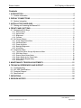
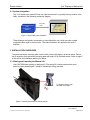
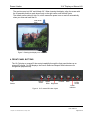
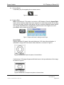
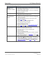
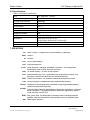
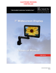
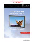
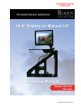
ELECTRONIC REVISION CONTROLLED Document Number 101844 Rev D Rosen Aviation 10.4” Display on Manual Lift Technical Manual, 10.4” Display on Manual Lift © 2008–2010 by Rosen Aviation, LLC All Rights Reserved The information contained herein is proprietary to Rosen Aviation, LLC. No part of this publication may be reproduced, transmitted, transcribed, stored in a retrieval system, or translated into any language in any form by any means without the written authorization from Rosen Aviation, LLC, except as allowed under copyright laws. Disclaimer of Liability The information contained in this document is subject to change without notice. Because we are continuously improving and adding features to our products, Rosen Aviation, LLC reserves the right to change specifications without prior notice. Rosen Aviation, LLC shall not be liable for technical or editorial errors or omissions contained herein. Rosen Aviation, LLC 1020 Owen Loop South Eugene, OR 97402 541.342.3802 888.668.4955 Fax: 541.342.4912 www.rosenaviation.com Document Number: 101844 Template: 4.2.3-6-FM; Revision A; 16 May, 2005 Revision: Date: 05/20/10 D Page 2 of 25 Rosen Aviation 10.4” Display on Manual Lift Contents 1. INTRODUCTION .................................................................................................................4 1.1. Product Information ......................................................................................................4 2. DISPLAY CONNECTIONS .................................................................................................4 2.1. System Integration ........................................................................................................5 3. INSTALLATION GUIDELINES ...........................................................................................5 3.1. Raising and Lowering the Manual Lift ...........................................................................5 4. FRONT PANEL BUTTONS.................................................................................................6 4.1. Navigational Soft Keys ..................................................................................................7 4.1.1. Source Select ................................................................................................................... 8 4.1.2. Aspect Ratio ..................................................................................................................... 8 4.1.3. Brightness......................................................................................................................... 9 4.1.4. Contrast .......................................................................................................................... 10 4.2. On-Screen Menus.......................................................................................................10 4.2.1. Image Adjustments Menu ............................................................................................... 11 4.2.2. Advanced Menu .............................................................................................................. 13 4.2.3. Power Up Mode .............................................................................................................. 14 4.2.4. Backlight Brightness ....................................................................................................... 15 4.2.5. Information...................................................................................................................... 15 4.3. Technician Menu ........................................................................................................16 4.3.1. Technician MenuImage Adjustments Menu ................................................................. 17 4.3.2. RGB Auto Detect ............................................................................................................ 18 4.3.3. Source Select Button Mode ............................................................................................ 18 4.3.4. Select Switch Active Pulse Width .................................................................................... 19 4.3.5. Select Switch Repeat Delay ............................................................................................ 19 4.3.6. Information...................................................................................................................... 20 5. MAINTENANCE: TENSION ADJUSTMENTS ..................................................................21 6. TECHNICAL REFERENCES AND SUPPORT .................................................................21 6.1. Troubleshooting ..........................................................................................................21 6.2. DO-160E Qualifications ..............................................................................................23 6.3. Technical Support .......................................................................................................23 6.4. Specifications..............................................................................................................24 7. DEFINITIONS ....................................................................................................................24 8. REVISION HISTORY ........................................................................................................25 Document Number: 101844 Template: 4.2.3-6-FM; Revision A; 16 May, 2005 Revision: Date: 05/20/10 D Page 3 of 25 Rosen Aviation 10.4” Display on Manual Lift 1. INTRODUCTION This manual describes how to install the Rosen 10.4” display on manual lift onto your aircraft. It contains everything you need to know to wire the display and confirm that it is functioning correctly. Note: Only trained and qualified personnel should perform installation and service. 1.1. Product Information The following documentation for the 10.4” display on manual lift specific to each display/video combination is available on the Rosen web site at www.rosenaviation.com. Outline and Installation Drawings, 10.4” manual lift 1043-229 or 1043-329 display on manual lift Technical Manual – (P/N 101844) User’s Guide 10.4” Display on Manual Lift – (P/N 101845) From the Rosen Aviation home page, select the Products tab and browse by product category. 2. DISPLAY CONNECTIONS There are several ways to connect the 10.4 display on manual lift to an aircraft’s entertainment system. Use the pinout descriptions on page 2 of the Outline and Installation drawing to assist in the wiring process. Pay close attention to the pinout information while completing wiring connections. The 10.4 display on manual lift is available in two different configurations depending on the video source that you install. Composite – model 1043-229 SDI (serial digital interface) – model 1043-329 The on-screen menus are different for each configuration. Some options will be shown even though they are not supported. Note: This display is for entertainment purposes only; connect to a non-critical power bus. Document Number: 101844 Template: 4.2.3-6-FM; Revision A; 16 May, 2005 Revision: Date: 05/20/10 D Page 4 of 25 10.4” Display on Manual Lift Rosen Aviation 2.1. System Integration The 10.4” display on a manual lift has one video source and it is typically the only monitor in the cabin, as shown in the following connection diagram. Composite or SDI Cabin Management System Figure 1 Single video input installation These displays are typically connected to a video distribution unit, which provides a single composite video signal to each monitor. The video distribution box performs the source selection. 3. INSTALLATION GUIDELINES To access the bottom mounting plate, use the latch to raise the display, as shown below. Secure the lift assembly from the bottom mounting plate with eight 10-32 flat head screws. Refer to page 2 of the outline and installation drawing for details. 3.1. Raising and Lowering the Manual Lift Use CAUTION when stowing or deploying lift. The spring lift is under pressure and could seriously injure hands/fingers if caught in mechanism during operation. To raise the display, pull the latch to the right. Figure 2 Manual lift assembly in stowed position Document Number: 101844 Template: 4.2.3-6-FM; Revision A; 16 May, 2005 Revision: Date: 05/20/10 D Page 5 of 25 10.4” Display on Manual Lift Rosen Aviation The monitor can pivot 180° and tilt back 30°. When lowering the display, align the screen with the lift assembly and then push down firmly on the right corner until the latch locks. The default power setting is Auto On, which means the power turns on and off automatically when you raise and lower the lift. Push down here Figure 3 Stowing the display on a manual lift 4. FRONT PANEL BUTTONS The 10.4” display on manual lift has control capability through the front panel buttons or an external IR remote. On SDI displays, the Source Select and Aspect Ratio buttons are for navigational purposes only. IR Sensor Source Select Aspect Contrast Ratio Brightness Figure 4 10.4” manual lift button layout Document Number: 101844 Template: 4.2.3-6-FM; Revision A; 16 May, 2005 Menu Power On/Off Power Indicator Revision: Date: 05/20/10 D Page 6 of 25 10.4” Display on Manual Lift Rosen Aviation Table 1 10.4 display on manual lift front panel buttons Button How it Works Power On/Off Turns the power on and off to the display. The LED indicator is red when the power is off, and green when the power is on. Previously adjusted settings of brightness and scaling mode are retained in memory when power is turned off, or when aircraft power is removed. Menu Opens a submenu of options to access other settings and fine-tune the display’s picture quality. For details about the on-screen menus, see OnScreen Menus in Section 4.2 on page 10. Contrast Adjusts the LCD contrast. See Contrast in Section 4.1.4 on page 10 for details. Brightness Adjusts the picture brightness. If the button is held down for more than one second the brightness will continue to step up or down in ¼–second intervals. For more information, see Brightness in Section 4.1.3 on page 9 for details. Aspect Ratio (Composite only) Two aspect ratio modes: Normal and Vertical Stretch change the proportions of the composite picture depending on the DVD format. On SDI displays, this button is for navigational purposes only. See Aspect Ratio in Section 4.1.2 on page 8 for details. Source Select Functions only as a secondary soft key for navigation in the on-screen menus. If pressing Source Select changes the picture to a black screen, set the Source Select Button Mode to External Select. See Source Select Button Mode in Section 4.3.3 on page 18 for details. 4.1. Navigational Soft Keys The icons on the display buttons indicate basic functions. In addition to the basic functions, the buttons act as soft keys that perform secondary navigational functions to adjust picture quality in setting screens and the on-screen menus. When you press a button and see a bar of blue soft keys, as shown below, press the corresponding display button. The label of the menu soft key changes depending on the function it is performing Secondary soft keys Basic function buttons Figure 5 Soft key buttons Selected options will be highlighted in yellow. The menu options that are available depend on the configuration and which source signal is active: composite or SDI. Note: Before changing the display settings, try both default color modes first to determine which set of colors you like best. See Restore Factory Defaults in Section 4.2.2.1 on page 13 for more information. Document Number: 101844 Template: 4.2.3-6-FM; Revision A; 16 May, 2005 Revision: Date: 05/20/10 D Page 7 of 25 10.4” Display on Manual Lift Rosen Aviation 4.1.1. Source Select A secondary key for navigating the on-screen menus. Figure 6 Source select button 4.1.2. Aspect Ratio Note: Composite only. This option is not active on SDI displays. Press the Aspect Ratio button (shown below) to adjust the picture expansion to most closely match the encoding of the source image. Press the ◄ or the ► soft key to switch the display between aspect ratio modes (described below). Highlight the optimal mode for the image source and press Set to set the mode and exit the screen. Figure 7 Aspect ratio button, settings, and soft keys Normal Mode Displays standard 4:3 aspect video and widescreen 16:9 video without alteration. A standard 4:3 image will fill the screen without distortion, as shown in Figure 8. Figure 8 Standard 4:3 aspect test pattern in Normal Mode A widescreen 16:9 image will appear with black bars on the top and bottom of the image, as shown in Figure 9. Figure 9 Widescreen 16:9 aspect test pattern in Normal Mode Document Number: 101844 Template: 4.2.3-6-FM; Revision A; 16 May, 2005 Revision: Date: 05/20/10 D Page 8 of 25 10.4” Display on Manual Lift Rosen Aviation Vertical Stretch Mode Expands the source video in the vertical dimension to fill the display screen. The top and bottom of a standard 4:3 image will be cropped and circles will appear as ovals, as shown in Figure 10. Figure 10 Standard 4:3 aspect test pattern in Vertical Stretch Mode Widescreen 16:9 videos will not exhibit black bars above and below the image but circles will appear as ovals, as shown in Figure 11. Figure 11 Widescreen 16:9 aspect test pattern in Vertical Stretch Mode 4.1.3. Brightness Adjust the picture brightness by pressing the Brightness button (shown below). Press the ◄ or the ► soft key to decrease or increase the brightness on the LCD. If the button is held down for more than one second, the brightness will continue to step up or down in ¼–second intervals. Press the Set soft key to set the brightness and exit the screen. Figure 12 Brightness button, settings, and soft keys Document Number: 101844 Template: 4.2.3-6-FM; Revision A; 16 May, 2005 Revision: Date: 05/20/10 D Page 9 of 25 10.4” Display on Manual Lift Rosen Aviation 4.1.4. Contrast Adjust the contrast by pressing the Contrast button (shown below). Press the ◄ or the ► soft key to raise or lower the contrast. Press the Set soft key to set the contrast and exit the screen. Figure 13 Contrast button, settings, and soft keys 4.2. On-Screen Menus To open the Main Menu and access the submenu settings, press the Menu button, as shown below. Press the ▼ and ▲ soft keys to select (highlight) an option, and press the OK soft key to select it. (Composite only) Figure 14 Composite and SDI Main Menu with soft keys Note: The on-screen menus will time out and close automatically after no screen activity for a preset amount of time, which is adjustable in the AdvancedMenu Timeout screen. Document Number: 101844 Template: 4.2.3-6-FM; Revision A; 16 May, 2005 Revision: Date: 05/20/10 D Page 10 of 25 10.4” Display on Manual Lift Rosen Aviation 4.2.1. Image Adjustments Menu Note: If the screen colors are not what you expect, try changing the default color modes to determine which one you like best before adjusting the other settings. See section 4.2.2.1 Restore Factory Defaults (Advanced Menu) on page 13 for details. Use the Image Adjustments menu options, as shown below, to control the color and picture quality. Press the Menu button and the OK soft key to open the menu. Close the menus using the Back and Exit options, or wait for the menu to close. (Composite only) Select Back and press the OK soft key to close this submenu and return to the Main Menu Set Contrast here or from the front panel button. See section 4.1.4 on page 10 about how it works. Figure 15 Image Adjustments menu and soft keys 4.2.1.1. Brightness To adjust the picture brightness, press the OK soft key to open the screen (Figure 16) below. Press the ◄ or the ► soft keys to change the brightness on the LCD accordingly. Press the Set soft key to set the brightness and exit the screen. Figure 16 Picture brightness settings and soft keys Document Number: 101844 Template: 4.2.3-6-FM; Revision A; 16 May, 2005 Revision: Date: 05/20/10 D Page 11 of 25 10.4” Display on Manual Lift Rosen Aviation 4.2.1.2. Saturation (Composite only.) To adjust the color saturation, press the Menu button and then select Image AdjustmentsSaturation using the soft keys. Press the ◄ or the ► soft keys to change the color levels. Press the Set soft key to set the saturation and exit the screen. Figure 17 Color saturation settings and soft keys 4.2.1.3. Tint (Hue) To adjust the color hues, press the Menu button and then select Image Adjustments Tint (Hue) using the soft keys. Press the ◄ or the ► soft keys to change the color hues in the image. Press the Set soft key to set the tint and exit the screen. Figure 18 Tint settings and soft keys 4.2.1.4. Sharpness To adjust the picture sharpness, press the Menu button and then select Image AdjustmentsSharpness using the soft keys. Press the ◄ or the ► soft keys to adjust the focus. Press the Set soft key to set the sharpness and exit the screen. Figure 19 Sharpness settings and soft keys Document Number: 101844 Template: 4.2.3-6-FM; Revision A; 16 May, 2005 Revision: Date: 05/20/10 D Page 12 of 25 10.4” Display on Manual Lift Rosen Aviation 4.2.2. Advanced Menu Use the Advanced menu options, as shown below, to control the display’s functionality. Press the Menu button and the OK soft key to open the menu. Close the menus using the Back and Exit options, or wait for the menu to close automatically. Select Back and press the OK soft key to close this submenu and return to the Main Menu Figure 20 Advanced menu and soft keys 4.2.2.1. Restore Factory Defaults (Advanced Menu) There are two Restore Factory Defaults in the on-screen menus. This one restores only the factory color screen settings: Vivid and Natural modes. Try both modes to determine which one you like best before adjusting the other picture quality settings. From the Advanced submenu, press the OK soft key to open the Restore Factory Defaults screen, as shown below. Change the color settings mode with any arrow soft key, and then press Set. A Restoring message will display on screen while the screen settings change. Figure 21 Restore Factory Defaults menu and soft keys Although the Restore Factory Defaults screen in the Technician and Advanced menus look alike, the Technician Menu option (see Section 4.3 on page 16) resets all default settings, not just color settings. Document Number: 101844 Template: 4.2.3-6-FM; Revision A; 16 May, 2005 Revision: Date: 05/20/10 D Page 13 of 25 10.4” Display on Manual Lift Rosen Aviation 4.2.2.2. Menu Timeout Use this option to set the amount of time the menu screens are visible, without making any changes, before they timeout and close automatically. From the Advanced submenu, press the ▼ soft key to select Menu Timeout and then OK, as shown below. Press the ◄ or ► soft key to select an option. Press the Set soft key to set the timeout and exit the screen. Figure 22 Menu timeout options and soft keys 4.2.3. Power Up Mode Choose from different options of turning on the display. From the Advanced submenu, press the ▼ soft key to select Power Up Mode and then OK to open the screen, as shown below. Restore Previous starts the display in the previously selected power state after a power interruption, regardless of the length of the power interruption. Press either ◄ or ► soft key to select the mode. Press the Set soft key to set the Power Up Mode and exit the screen. Figure 23 Power Up mode options and soft keys Document Number: 101844 Template: 4.2.3-6-FM; Revision A; 16 May, 2005 Revision: Date: 05/20/10 D Page 14 of 25 10.4” Display on Manual Lift Rosen Aviation 4.2.4. Backlight Brightness Use this setting to adjust the intensity of the LCD backlight. From the Advanced submenu, press the ▼ soft key to select Backlight Brightness and then press OK to open the screen, as shown below. Press the ◄ or the ► soft keys to change the image on the LCD accordingly. Press the Set soft key to set the brightness and exit the screen. Figure 24 Picture brightness settings and soft keys 4.2.5. Information Use the Information screen to review operating status of the display and to access the Technician Menu. From the Main Menu, press the ▼ soft key to select Information and then OK. A. Composite mode B. SDI mode Figure 25 Read-only screens about operating status Document Number: 101844 Template: 4.2.3-6-FM; Revision A; 16 May, 2005 Revision: Date: 05/20/10 D Page 15 of 25 10.4” Display on Manual Lift Rosen Aviation 4.3. Technician Menu To protect the display from accidental or unintentional adjustments, the Technician Menu is accessible only with a special button combination. To avoid repeating this button sequence after each change, the menu remains active until you manually close it. Note: The Main Menu options are not selectable while the Technician Menu is open. To open the Technician Menu, start with the display on, and press the following front panel keys in this order: 1. 2. 3. 4. 5. Menu Press the ▼ soft key to select the Information option on the Main Menu. Inside the Information screen, press the soft keys in this order: ◄, ►, ◄◄, ►►. Then press the Back soft key. The Technician Menu opens. Resets all default settings. See also Advanced MenuRestore Factory Defaults in Section 4.2.2.1 on page 13. Composite only. The Image Adjustments options in the Technician Menu are different from those in the Main Menu A. Composite mode B. SDI mode Figure 26 Technician menus and soft keys Note: The RS485 Address Selection is not supported in this model. To select a menu option, press any arrow soft key to highlight and press OK. To close the Technician menu, press the ▼ soft key and choose Exit or allow the screen to timeout and close automatically. To open the Technician Menu again, press the Menu button. To exit the Technician Menu Mode and return to the Main Menu, repeat steps 2–4 (above). The Main Menu will open. Document Number: 101844 Template: 4.2.3-6-FM; Revision A; 16 May, 2005 Revision: Date: 05/20/10 D Page 16 of 25 10.4” Display on Manual Lift Rosen Aviation 4.3.1. Technician MenuImage Adjustments Menu (Composite only.) Use the following options to adjust the intensity of the three primary colors when running the display in composite mode. Figure 27 Image Adjustments menu and soft keys 4.3.1.1. Red Adjusts the low-level registers of the red values in the picture. From the Technician MenuImage Adjustments Menu, press the ▼ soft key to select Red and then OK, as shown below. Press the ◄ soft key to show more cyan tones or ► to intensify the red tones. Press the Set soft key to set the value and exit the screen. Figure 28 Red settings and soft keys 4.3.1.2. Green Adjusts the low-level registers of the green values in the picture. From the Technician MenuImage Adjustments Menu, press the ▼ soft key to select Green and then OK, as shown below. Press the ◄ soft key to show more magenta tones or ► to intensify the green tones. Press the Set soft key to set the value and exit the screen. Figure 29 Green settings and soft keys Document Number: 101844 Template: 4.2.3-6-FM; Revision A; 16 May, 2005 Revision: Date: 05/20/10 D Page 17 of 25 10.4” Display on Manual Lift Rosen Aviation 4.3.1.3. Blue Adjusts the low-level registers of the blue values in the picture. From the Technician MenuImage Adjustments Menu, press the ▼ soft key to select Blue and then OK, as shown below. Press the ◄ soft key to show more yellow tones or ► to intensify the blue tones. Press the Set soft key to set the value and exit the screen. Figure 30 Blue settings and soft keys 4.3.2. RGB Auto Detect Use RGB Auto Detect to automatically switch to RGB when the source is connected instead of manually selecting the RGB source with the Source Select button. To open this setting, press Menu to open the Technician Menu, press the ▼ soft key to select RGB Auto Detect, and then press OK. Use any arrow key to choose the setting, and then click Set to close the screen. The action of the display changes based on what you select. Figure 31 RGB Auto Detect settings and soft keys 4.3.3. Source Select Button Mode (Composite mode only.) There is no source select on the 10.4” display on manual lift. External Select sends a source change request to an external device to change between its sources. To open the Source Select Button Mode screen, press Menu to open the Technician Menu, press the ▼ soft key to select Source Select Button Mode, and then press OK. Press the ▼ soft key to choose the setting, and then press Set to close the screen. Keep this option set to External Select Figure 32 Source Select Button Mode settings and soft keys Document Number: 101844 Template: 4.2.3-6-FM; Revision A; 16 May, 2005 Revision: Date: 05/20/10 D Page 18 of 25 10.4” Display on Manual Lift Rosen Aviation 4.3.4. Select Switch Active Pulse Width Use Select Switch Active Pulse Width to set the pulse width of the source select signal. Pulse width is the amount of time the switch is closed. From the Technician Menu, press the ▼ soft key to choose Select Switch Active Pulse Width and then OK to open the screen, as shown below. Press the ◄ soft key to decrease the pulse width, or the ► soft key to increase the pulse width. Press the Set soft key to set the pulse width and exit the screen. Each increment changes the pulse width by 50mSec. The maximum pulse width is 1.1 second. Figure 33 Select Switch Active Pulse Width settings and soft keys 4.3.5. Select Switch Repeat Delay Use Select Switch Repeat Delay to change the time delay between source select clicks on the display. From the Technician Menu, press the ▼ soft key to choose Select Switch Repeat Delay, and then OK to open the screen, as shown below. Press the ◄ soft key several times to shorten the time delay between repeats, or press the ► soft key several times to lengthen the repeat delay time. Press the Set soft key to set the repeat delay time and exit the screen. Figure 34 Select Switch Repeat Delay settings and soft keys Document Number: 101844 Template: 4.2.3-6-FM; Revision A; 16 May, 2005 Revision: Date: 05/20/10 D Page 19 of 25 10.4” Display on Manual Lift Rosen Aviation 4.3.6. Information To review the operating status information about the display, open the Technician Menu, press the ▼ soft key to select Information, and then press OK. Press Back to close the screen. A. Composite mode B. SDI mode Figure 35 Read-only screen about the display’s operating status Document Number: 101844 Template: 4.2.3-6-FM; Revision A; 16 May, 2005 Revision: Date: 05/20/10 D Page 20 of 25 10.4” Display on Manual Lift Rosen Aviation 5. MAINTENANCE: TENSION ADJUSTMENTS The following photos show where to adjust the pivot and tilt tension, and which tools to use. TILT ADJUST 5/32” hex key PIVOT ADJUST 5/32” hex key Figure 36 Areas on the manual lift to make tension adjustments 6. TECHNICAL REFERENCES AND SUPPORT The Outline & Installation drawing is available at www.rosenaviation.com. From the Rosen Aviation home page, select the Products tab and browse by product category. 6.1. Troubleshooting If the display does not function properly, refer to the following troubleshooting tips for symptoms and possible solutions before contacting Rosen Aviation field support. Document Number: 101844 Template: 4.2.3-6-FM; Revision A; 16 May, 2005 Revision: Date: 05/20/10 D Page 21 of 25 10.4” Display on Manual Lift Rosen Aviation Table 2 Troubleshooting tips and solutions Problem Power LED does not illuminate (neither RED nor GREEN) Possible Solutions Verify pinout to base receptacle is correct (power input connection) Verify voltage to monitor is correct Check the arm and base receptacle connectors for damaged pins Check for damaged pins in base Monitor not turned on Power LED is red If pushing the power button does not turn the power LED green, the display failed. Please call customer service. Power LED is green but no video displays (black screen) Verify pinout to base receptacle is correct. Check the arm and base receptacle connectors for damaged pins (video input connection) Verify Image Adjustment values are not set to 0 (zero). See Section 4.2.1 on page 11. Verify that video source is on and displaying video Verify that video source is in play mode Verify video signal at monitor connector Check for damaged pins in base Press Source Select button. See Source Select Button Mode in Section 4.3.3 on page 18 for more information. Distorted image Wrong colors Document Number: 101844 Template: 4.2.3-6-FM; Revision A; 16 May, 2005 Verify that the pinout is correct Verify that the signal is present and accurate Examine the display for pinched or damaged cables. Verify NTSC input Check for damaged pins in base Ensure the internal system temperature is not above or below the allowed parameters. Try changing the aspect ratio. See Aspect Ratio in Section 4.1.2 on page 8 for more information. If the screen colors are not what you expect, change modes in Advanced MenuRestore Factory Defaults. Two modes are available: Normal and Vivid. Try both modes to determine the one you like best before adjusting the other screen settings. See Restore Factory Defaults in Section 4.2.2.1 on page 13 for more information. Revision: Date: 05/20/10 D Page 22 of 25 10.4” Display on Manual Lift Rosen Aviation 6.2. DO-160E Qualifications Table 3 DO 160E Test Criteria to which we test the 1043 series displays Description DO-160E Section DO-160E Category Temperature and Altitude 4.0 A1 Temperature Variation 5.0 C Humidity 6.0 A Operational Shocks & Crash Safety 7.0 B Vibration 8.0 S, Curve B Explosive Atmosphere 9.0 N/A Waterproofness 10.0 N/A Fluids Susceptibility 11.0 N/A Sand and Dust 12.0 N/A Fungus Resistance 13.0 N/A Salt Fog 14.0 N/A Magnetic Effect 15.0 Z Power Input 16.0 Z,B Voltage Spike 17.0 A Audio Frequency Conducted Susceptibility – Power Inputs 18.0 Z Induced Signal Susceptibility 19.0 AC Radio Frequency Susceptibility (Radiated and Conducted) 20.0 T Emission of Radio Frequency Energy 21.0 B/M* Lightning Induced Transient Susceptibility 22.0 N/A Lightning Direct Effects 23.0 N/A Icing 24.0 N/A Electrostatic Discharge (ESD) 25.0 A Fire, Flammability tested to 14 CFR 25.853 Appendix F, 12-second vertical burn test *Notes: Model 1043-229 (composite video) meets Cat B Model 1043-329 (SDI video) meets Cat M 6.3. Technical Support If you need assistance with an installation, please contact Rosen Aviation at 541.342.3802 or 888.668.4955. Document Number: 101844 Template: 4.2.3-6-FM; Revision A; 16 May, 2005 Revision: Date: 05/20/10 D Page 23 of 25 10.4” Display on Manual Lift Rosen Aviation 6.4. Specifications Table 4 1043 display specifications Size 10.4” diagonal, 4 : 3 format Resolution 1024 x 768 Viewing Angle (U/D/L/R) 88/88/88/88 Brightness 400 cd/m2 Contrast Ratio 1200 : 1 Video Input 1Vp-p, 75 ohms Video Standards NTSC, PAL, SECAM Graphics Standards XGA Weight 12.1 lbs [1.4515 kg] (monitor only) Dimensions 15.48” (W) x 23.4” (H) x 3” (D) [39.32 cm (W) x 59.44 cm (H) x 7.62 cm (D)] Power Requirements 28V DC Operating Temperature 0ºC - 50ºC 7. DEFINITIONS DC Direct Current – voltage from an aircraft battery or generator. GND Ground IR Infrared LCD Liquid crystal display LED Light emitting diode NTSC North American Television Standards Committee – the analog video specification used in North American countries OSD On screen display – a menu of user options PAL Phase alternate (by) line – the analog video specification used by most European countries and their former colonies world wide PCB Printed circuit board – an electronics assembly that performs tasks PS2 Personal system 2 (trademarked IBM keyboard specification) RS-232 Standard for transmitting serial information using single-ended signaling (data lines referenced to ground). RS-485 A physical layer electrical specification of a two-wire, half-duplex, multipoint serial connection. The standard specifies differential signaling to improve noise immunity over RS-232. RGB Red, green, blue. An abbreviation commonly used for analog computer graphics video that transmits the three primary colors on separate wires. SDI Serial digital interface Document Number: 101844 Template: 4.2.3-6-FM; Revision A; 16 May, 2005 Revision: Date: 05/20/10 D Page 24 of 25 10.4” Display on Manual Lift Rosen Aviation SECAM (Séquentiel couleur à mémoire. French for "sequential color with memory"), an analog color video system first used in France USB Universal serial bus. A high-speed differential signaling serial bus typically used to connect peripheral devices to a personal computer. Vp-p Volts peak-to-peak; the maximum range of a sine wave. XGA Extended Graphics Array 8. REVISION HISTORY Revision Date Revision Description A 07/31/08 New release 08265 B 08/13/08 Update DO-160E, Section 15, from A to Z 08337 C 6/8/09 Add video standards and graphic standards to section 6.4 09205 D 05/20/10 Add SDI video source and OSD changes 10264 Document Number: 101844 Template: 4.2.3-6-FM; Revision A; 16 May, 2005 EC # Revision: Date: 05/20/10 D Page 25 of 25