1
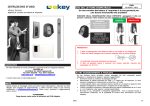
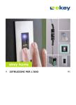
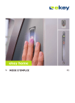
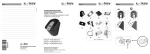
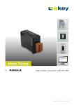
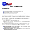
INSTALLATION & OPERATING MANUAL
Access system with finger scan
Index of contents
SCOPE OF SUPPLY ..............................................................3
DEVICE OVERVIEW.............................................................4
INSTALLATION ...................................................................5
OPERATION ........................................................................8
POSSIBLE PROBLEM AREAS AND SOLUTIONS...................12
TECHNICAL DATA .............................................................13
FURTHER INFORMATION ..................................................14
NOTES ..............................................................................15
-2-
Scope of supply
1. Scope of supply
•
•
•
•
•
•
•
•
•
Outside unit (“OU”)
Mounting plate for inside and outside unit
Inside unit (“IU”)
4 screws and pins for outside unit
External power supply
User list
Warranty card
Installation – and operating manual
Quick user guide
Mounting plate IU
Mounting plate OU
Inside unit
Power supply
Screws and pins
Warranty card
Quick user guide
1.1
Outside unit
Manual
User list
Additional parts provided with ekey TOCAhome pc
TOCAhome pc can be connected to a personal computer via serial interface. The items listed below are the
additional components that are included with TOCAhome pc package.
Serial cable
CD-ROM
-3-
Device overview
2. Device overview
serial interface (only for
ekey TOCAhome pc
display
connecting clamp for
power supply
marking
arrows
4 operation
keys
sensor
status
display
clamp 1 and 2
(connection with
outside unit)
ekey TOCA home
comes with one relay, ekey
TOCAhome 3 and TOCAhome
pc with three relays in order
to connect door openers etc.
clamp 3 and 4
(connection with
outside unit)
Your product is set up with a finger scanner. This finger scanner reads special characteristics of your
finger lines and uses them for identification. Each of your fingers is unique and differs from the fingers of
other persons.
Model ekey TOCAhome
This model provides 1 relay.
Model ekey TOCAhome 3
This model provides 3 relays. You can assign these relays to different fingers. This can be used for
example to switch a door opener, a garage opener or an alarm device.
Model ekey TOCAhome pc
Like TOCAhome 3 this model also provides 3 relays. Moreover, you can connect the inside unit to a
personal computer using a serial interface cable.
-4-
Installation
3. Installation
3.1. Wall fastening of outside unit
Install the Mounting plate (as shown in the
directly on the wall. The ideal installation
approximately 135 cm / 52 inches (upper
fingerprint reader is ergonomically positioned for
finger surface as it is being swiped.
180 cm
135 cm
The unit can be mounted to a standard electrical
mounting set“ accessory. The mounting holes
assemblage on a standard electrical outlet
you can work with pins or wooden screws or
the wall.
illustration besides)
height is at
edge). At this height the
better reading of the
outlet using ”In-wall
are designed to make the
possible. Alternatively,
similar screws directly on
The outside unit (splash water resistant) has to be installed in a place, where it is safe from the impact of
heavy rain or snowfall as well as from too strong an incident of solar radiation.
3.2. Wall fastening of inside unit
Mount the “fitting plate”, which can be found at the backside of the inside unit. The “fitting plate” at the
same time serves as fastener for the casing of the inside unit. Put up the inside unit onto the fitting plate.
Inside unit can be opened by pushing up the lock clip with a flat screwdriver.
The inside unit has to be installed in a way that it is safe from third party access. Security risk!
Note:
Installation of inside unit shall be exclusively executed by qualified
personnel!
3.3. Electrical connection
The inside unit has to be supplied with electricity; its voltage is 9 VAC. Please use the “9VAC – in”
connecting clamps and only use the power supply provided with your TOCAhome product.
The inside and outside unit have to be connected via a 4-lines wire (bell wire, CAT 5/6, …) with a
minimum line diameter of 0,75mm² (gauge 21) using connection clamps 1-4. In the case of a wire length
of more than 20m the diameter of the wire has to be enlarged and a screened cable has to be used.
1 relay (3 relays with the product ekey TOCAhome 3) is available for controlling external switchgear. The
programming is carried out via the programming menu. The relay is equipped with a change-over contact,
which is freely usable, the maximum switching power is 250V~5A. Each door opener has to be connected
to a dedicated power supply without exception (don’t use the power supply provided with you TOCAhome
product!).
The connection wire between outside and inside unit is to be run separately from electronic house
installations, as they send out signals in the lower voltage area, which can be irritated by other
neighbouring live power cables.
Remark:
The cables are not protected against reversed polarity.
Note:
It is strongly recommended to have the electrical connection done only
by qualified personnel!
-5-
Installation
3.4.
Connection diagram
Inside unit
NC
NO
C
Channel1
1 2 C NONC
3 4
9VAC
Outside unit
1 2 3 4
ESC
<
9V~
>
ekey TOCAhome
OK
Inside unit
C
NC
NO
Channel1 Channel2 Channel3
1 2 C NONC C NONC C NONC
3 4
9VAC
Outside unit
1 2 3 4
ESC
<
9V~
>
ekey TOCAhome 3
OK
-6-
Installation
Example: Connecting to a door opener
Internal unit with dry contact
C
NC
NO
110 V~
Relay
Channel1
1 2
C NO NC
Power supply
-7-
Door opener
Operation
4. Operation
4.1. Using the operation keys of inside unit
Programming is carried out by the usage of 4 keys: Å Æ OK ESC
ESC
Å
Æ
OK
OK serves to enter the menu and to confirm your input.
Å and Æ serves to change the values in the display and respectively for navigation respectively as shown
in the illustration of programming menu in chapter 4.3.
ESC serves to cancel the current selection.
Program-, menu functions and display
Normal operation
Enrol user
Delete user
Security code setting
Reset to initial settings
(deletes all user settings and data)
. (blinking)
Eu
du
Sc
rr
4.2. Initial operation:
Coupling between inside and outside unit
After applying power, the two dots (..) in the display of the inside unit will illuminates and the status
display of the outside unit will start blinking.
Press the OK key followed by the ESC key . The initialising process runs fully automated, whereby the
devices are coupled with each other. During this process, which lasts for approx. 15 sec. the display
shows OK.
This coupling is used to secure that the outside unit cannot be misused or changed to prevent
unauthorised persons from getting access.
After initialization is completed, a single blinking dot signals normal operation. The standard security code
which is automatically used is 99. Please change this code to your own individual code.
Note:
The exchange of the outside unit is only possible via resetting the
system to the initial settings. All data are erased in this case. You have
to carry out the initialisation once again. All fingers have to be enrolled
again in the system after this reset.
-8-
Operation
4.3. Programming menu
. (blinking)
Normal operation
Control keys for the
internal unit
00 ... 99
Enter the security code
Enter the left number of
your security code followed
by the OK key. Enter the
right number of the
security code. The initial
standard code is 99. Press
OK. Should you key in the
wrong code 3 times, the
system will be locked for
30 mins.
Eu
enroll user
This menupoint is used to
enroll fingers in the
system.
Terminates the operation
in the menu, respectively
jumps one menupoint
higher
ESC
Right, left navigation in
the menu, respectively
changes values in the
display
du
delete user
This menupoint is used to
delete users. For the user
selected all fingers enrolled
are deleted.
Æ
Å
OK
Sc
Security code
This menupoint is used to
set the security code
(initial standard setting is
99). It is recommended to
change this standard code
to an individual code.
Confirmation,
respectively jumps one
menupoint lower
rr
Reset to initial standard
settings
This menupoint is used to
reset to the initial standard
settings. All data is deleted
without recall. Use rr
before you hand over the
system to another owner.
00
Enter the security code
1 ... 99
Set user number
1 ... 99
Set user number
Each user has its own user
number. A user number
which is already in use, is
marked with a blinking dot
after the number.
Each user has its own user
number. A user number
which is already in use, is
marked with a blinking dot
after the number.
00 ... 99
Enter new security codes
First enter the left number
of your security code,
followed by the right one.
Without keying in your
new security code, you
can not access the
system anymore.
Enter the left number of
your security code followed
by the OK key. Enter the
right number of the
security code. The initial
standard code is 99. Press
OK. If you key in the
wrong code 3 times, the
system will be locked for
30 mins.
In case you forget your
security code, the only
solution possible is to
reset the system to the
initial standard settings.
F1 ... F0
Set finger number
Each finger of a user is
saved by using a number.
Chose here the number of
your finger. Start to count
with one at the little left
finger. Count the fingers to
the right little finger until
10. Instead of 10 the
display shows 0.
o1 ... o3
Enter output (channel)
The finger, which has been
enrolled in the former
menu is now assigned to a
certain channel. For
example the forefinger is
used to unlock channel 1.
Note:
The word „channel“ and
„relay” are used
interchangeably.
EF
Enroll Finger
The sensor of the external
unit is activated. The
status display is orange.
Go to the external unit and
drag your finger - as
described in the operating
manual - over the sensor.
The status display now is
green, which means the
finger has been enrolled
successfully.
-9-
Operation
4.4. Enrolment of a finger
4.4.1. How to swipe a finger correctly over the sensor
In order for the reader to properly scan and recognize a particular finger, the finger needs to be
positioned and swiped correctly over the sensor as outlined below:
a. Locate the reader sensor between the 2 green illuminated arrows.
b. Starting from the finger joint, place the finger flat over the sensor. It is very important that the
whole finger is placed flat over the senor and not just the tip.
c. Apply little pressure and start swiping the finger immediately all the way down. The bigger the
identified finger surface, the higher is the probability that you are recognised again by the system.
Sensor
Recommended
finger area
- 10 -
Operation
4.4.2. How to Enrolment of a finger
1. Press the OK key in the inside unit.
2. By using the keys Å and Æ enter the left number of the security code (standard setting is 9)
3. Press OK
4. By using the keys Å and Æ enter the right number of the security code (standard setting is 9)
5. Press OK
6. In the display „Eu“ (enrol user) is illuminated
7. Press OK
8. The display shows “1“. A flashing dot next to the number signals that this user number is already in
use. Example: “1.” Assign the desired user number by using the keys Å and Æ.
9. Press OK
10. The display shows “F1”. F1 stands for finger 1. Please start to count your fingers at the left hand with
the little finger. The right little finger has the number 10 (setting “F0” in the display). A flashing dot
next to the number signals that this user number is already in use e.g. for the right forefinger set „F7“
11. Press OK
12. In the version ekey TOCAhome the display shows “EF”. Please continue reading at the next point but
one. In the version TOCAhome 3 you can now determine which relay (channel) should be activated by
the selected finger: “01” is shown. Set the desired channel by using the keys Å and Æ and press OK.
(Channel 1 is signalised in the display by “01”.)
13. The display shows “EF” (Enrol Finger). You now have 60 sec to draw your finger over the sensor.
14. The outside unit has a status display, which signals the state of operation in different colours.
Red
The finger could not be scanned successfully
Green
Successful scan
Orange
Operating state “enrolment”. The device is waiting for a finger to be scanned.
Note:
Please try to swipe the finger’s biggest area possible over the sensor - starting from the
beginning of the finger joint. This way, you achieve highest possible identification efficiency.
4.5. Deleting a finger
1. Press the OK key in the inside unit.
2. By using the keys Å and Æ enter the left number of the security code (standard setting is 9)
3. Press OK
4. By using the keys Å and Æ enter the right number of the security code (standard setting is 9)
5. Press OK
6. In the display „Eu“ (enrol user) is illuminated
7. By using the keys Å and Æ navigate to “du“ (delete user)
8. Press OK
9. By using the keys Å and Æ choose the user number you intend to delete from the system.
10. Press OK
11. OK is illuminated in the display
12. After pressing OK again the device returns to its normal operation (flashing)
4.6. Reset to standard setting
This process is thought for the case of handing over the device to a new owner or user.
When returning to the initial settings all data from the storage are deleted. The security code is set back
to the factory setting of 99 and both inside and outside unit loses their coupling.
1.
2.
3.
4.
5.
6.
7.
8.
9.
Press the OK key in the inside unit.
By using the keys Å and Æ enter the left number of the security code (standard setting is 9)
Press OK
By using the keys Å and Æ enter the right number of the security code (standard setting is 9)
Press OK
In the display „Eu“ (enrol user) is illuminated
By using the keys Å and Æ navigate to “rr“ (delete user)
Press OK
Enter the security code again (see steps 1-5)
Now the display shows “_._” and in the following for approx. 15 sec “OK” and then “. .” like after delivery.
The inside and outside unit are ready for initial operation.
- 11 -
Possible problem areas and solutions
5. Possible problem areas and their solutions
Problem
Reason
Solution
The enrolment of a finger is not
successful
The finger has not been drawn
consistently starting from the
finger joint over the senor.
The finger has been drawn too soft
or too strongly over the sensor.
The finger has been drawn too fast
or too slowly over the sensor.
Draw the finger consistently over the
sensor.
Draw the finger gently, but not too softly
over the finger.
Draw the finger with moderate speed over
the sensor.
An already enrolled finger cannot
be found
During enrolment another area of
the finger was scanned.
The enrolment has not been
carried out correctly
Status point of the inside unit is
not flashing
E0
Break down of the system
The finger has to be enrolled again by
drawing it consistently over the sensor.
See “Enrolment of a finger is not working”
– perfect enrolment ensures high
identification efficiency.
Turn off the device for approx. 20 sec.
No connection to the outside unit
Check the „4-line” connection wire.
E1
Already 99 fingers enrolled
E2
30min locking after 3 times
entering the wrong security code
Wrong unit coupling. The green
LED on the outside unit is
signalling a positive identification,
which is not accepted, because one
of the devices has been changed.
It is not possible to enrol more fingers. If
necessary erase fingers in order to enrol
new ones.
Wait for 30 min., in order to key in the
security code anew.
After exchange of the outside or inside
unit a reset to the initial settings has to
be carried out.
E3
- 12 -
Technical data
6. Technical data
•
•
•
•
•
Connections
o Connection between inside and outside unit
o 1x (3x version TOCAaccess light+) relay 250V~ 5A
o 9VAC with supplied external adaptor
Memory
o 99 fingers possible
o No loss of data after power failure
Security
o Coupling between inside and outside unit
o Extremely low rate of false identification
power consumption
o max. 7W
Speed
o Recognition time <20ms per stored finger
o Enrolment time ~1,2s per finger
Recommended diameters of the wires:
Length of wire
< 20 m
> 20m
Min. diameter of the lines
0,75mm²
Diameter of the wire has to be enlarged accordingly
- 13 -
Type
unscreened
screened cable
Further information
Please find further information on our homepage www.ekey.net. There you can find up-to-date hints and
FAQ’s.
- 14 -
Notes
7. Notes
- 15 -
Copyright by ekey biometric systems, subject to changes, errors excepted. No responsibility is accepted for the correctness of
the information given.
ekey biometric systems GmbH & Co KG
Lunzerstraße 64
A-4030 Linz
www.ekey.net
- 16 -