1
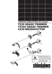
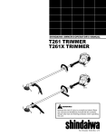
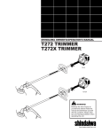
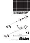
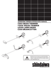
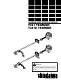
SHINDAIWA OWNER’S/OPERATOR’S MANUAL
T261 TRIMMER
T261X TRIMMER
T261
T261X
WARNING!
Minimize the risk of injury to yourself and others! Read
this manual and familiarize yourself with the contents.
Always wear eye and hearing protection when operating
this unit.
Part Number 81646 Rev. 1/07
Introduction
Attention Statements
The Shindaiwa T61 Series hand held
power equipment has been designed and
built to deliver superior performance
and reliability without compromise to
quality, comfort, safety or durability.
Throughout this manual are special
“attention statements”.
Shindaiwa engines represent the leading
edge of high-performance engine technology, delivering exceptionally high
power with remarkably low displacement and weight. As an owner/operator,
you’ll soon discover for yourself why
Shindaiwa is simply in a class by itself!
IMPORTANT!
The information contained in this owner's/operator's manual describes units
available at the time of publication.
Echo
Inc. reserves
the right
to make
Shindaiwa
Inc. reserves
the right
to
changes
to
products
without
prior
make changes to products without
notice,
andand
without
obligation
prior notice,
without
obligationtoto
make
alterations
to units
previously
make alterations
to units
previously
manufactured.
manufactured.
WARNING!
The engine exhaust from
this product contains chemicals
known to the State of California to
cause cancer, birth defects or other
reproductive harm.
Contents
PAGE
Attention Statements ...............................
Genereal Safety Instructions ..................3
Safety Labels .............................................4
Product Description .................................5
Specifications ............................................5
Assembly and Adjustments .....................6
Fuel ............................................................9
Starting the Engine ..................................9
Stopping the Engine ..............................10
Adjusting Engine Idle ............................10
Checking Unit Condition.......................11
Shoulder Strap ........................................11
Cutting Grass..........................................11
Using a Blade (T61X) ..........................1
Maintenance ...........................................13
Long Term Storage ................................15
Troubleshooting Guide .........................16
Emission System Warranty ...................19
2
WARNING!
A statement preceded by
the triangular attention
symbol and the word “WARNING”
contains information that should be
acted upon to prevent serious bodily
injury.
Read and follow this
operators manual.
Failure to do so could
result in serious injury.
Wear eye and hearing
protection at all times
during the operation
of this unit.
Keep bystanders
at least 50 feet (15 m)
away during operation.
Beware of thrown or
ricocheted objects.
CAUTION!
A statement preceded by the word
“CAUTION” contains information
that should be acted upon to prevent
mechanical damage.
IMPORTANT!
A statement preceded by the word
“IMPORTANT” is one that possesses
special significance.
NOTE:
A statement preceded by the word “NOTE”
contains information that is handy to know
and may make your
job easier.
Do not operate this unit with a
blade unless the unit is equipped
with a Shindaiwa-approved
handlebar or barrier.
Always wear a harness when
operating this unit with a blade.
A harness is also recommended
when using trimmer line.
If unit is used as a brushcutter,
beware of blade thrust. A jammed
blade can cause the unit to jerk
suddenly and may cause the
operator to lose control of the unit.
IMPORTANT!
The operational procedures described
in this manual are intended to help you
get the most from this unit as well as to
protect you and others from harm. These
procedures are guidelines for safe operation under most conditions, and are not
intended to replace any safety rules and/
or laws that may be in force in your area.
If you have questions regarding your
T261 series hand held power equipment,
or if you do not understand something
in this manual, your Shindaiwa dealer
will be glad to assist you. You may also
contact Echo Inc. at the address
printed on the back of this Manual.
General Safety Instructions The Properly Equipped Operator
Work Safely
Shindaiwa trimmers operate at very high
speeds and can do serious damage or
injury if they are misused or abused.
Never allow a person without training or
instruction to operate this unit!
WARNING!
Never make unauthorized
attachment installations. Do not
use attachments not approved by
Shindaiwa for use on this unit.
Wear close-fitting clothing to
protect legs and arms. Gloves
offer added protection and
are strongly recommended.
Do not wear clothing or
jewelry that could get caught
in machinery
or underbrush.
Secure hair so it is
above shoulder
level. NEVER
wear
shorts!
Wear hearing protection devices
and a broad-brimmed hat or
helmet.
Always wear eye protection such as
goggles or safety glasses.
Always operate with both
hands firmly gripping the
unit.
Stay Alert
You must be physically and mentally fit to
operate this unit safely.
WARNING!
Never operate power equipment
of any kind if you are tired or if you
are under the influence of alcohol,
drugs, medication or any other substance that could affect your ability
or judgement.
WARNING!
Minimize the Risk of
Fire
n NEVER smoke or light fires near
the engine.
n ALWAYS stop the engine and
allow it to cool before refueling.
Avoid overfilling and wipe off any
fuel that may have spilled.
n ALWAYS inspect the unit for fuel
leaks before each use. During
each refill, check that no fuel
leaks from around the fuel cap
and/or fuel tank. If fuel leaks
are evident, stop using the unit
immediately. Fuel leaks must be
repaired before using the unit.
n ALWAYS move the unit to a place
well away from a fuel storage
area or other readily flammable
materials before starting the engine.
n NEVER place flammable material
close to the engine muffler.
n NEVER operate the engine without the spark arrester screen in
place.
Keep away from the rotating trimmer line or blade at all times, and
never lift a moving attachment
above waist-high.
DO NOT OPERATE THIS UNIT
IF YOU ARE TIRED, ILL OR
UNDER THE INFLUENCE OF
ALCOHOL, DRUGS, OR
MEDICATION.
Keep a proper footing
and do not overreach—maintain
your balance at all
times during operation.
Always make sure
the appropriate
cutting attachment
shield is correctly
installed and in good
condition.
Wear appropriate footwear (non-skid
boots or shoes): do not wear opentoed shoes or sandals. Never operate
the unit while barefoot!
Figure 1
WARNING! Use Good Judgment
n ALWAYS wear eye protection to
shield against thrown objects.
n NEVER operate the engine
when transporting the unit.
n NEVER operate the engine
indoors! Make sure there is
always good ventilation. Fumes
from engine exhaust can cause
serious injury or death.
n ALWAYS clear your work area
of trash or hidden debris that
could be thrown back at you or
toward a bystander.
n ALWAYS use the proper cutting
tool for the job.
n ALWAYS stop the engine immediately if it suddenly begins
to vibrate or shake. Inspect for
broken, missing or improperly
installed parts or attachments.
n NEVER extend trimming line beyond the length specified for your
unit.
n ALWAYS keep the unit as clean
as practical. Keep it free of loose
vegetation, mud, etc.
n ALWAYS hold the unit firmly with
both hands when cutting or trimming, and maintain control at all
times.
n ALWAYS keep the handles clean.
n ALWAYS disconnect the spark
plug wire before performing any
maintenance work.
n ALWAYS, if a saw blade should
bind fast in a cut, shut off the
engine immediately. Push the
branch or tree to ease the bind
and free the blade.
3
3
Be Aware of the Working Environment
Make sure bystanders or observers
outside the 50-foot “danger zone”
wear eye protection.
Avoid long-term operation
in very hot or very cold
weather.
50
FEET
Be extremely
careful of slippery terrain,
especially during
rainy weather.
If contact is made with a hard object,
stop the engine and inspect the cutting
attachment for damage.
Reduce the risk of
bystanders being struck
by flying debris. Make
sure no one is within 50
feet (15 meters)—that’s
about 16 paces—of an
operating attachment.
Always make sure the
appropriate cutting
attachment shield is
correctly installed.
When operating in rocky terrain or near electric
wires or fences, use extreme caution to avoid contacting such items with the cutting attachment.
Be constantly alert for objects and debris that could be thrown
either from the rotating cutting attachment or bounced from a
hard surface.
Figure 2
Safety Labels
IMPORTANT!
Safety and Operation Information Labels: Make sure all information labels are undamaged
and readable. Immediately replace damaged or missing information labels. New labels are
available from your local authorized Shindaiwa dealer.
This label indicates the minimum
distance between front handle and
rear grip per ANSI B175.3.
T261
Figure 3
44
T261X
Product Description
T261 TRIMMER
Spark Plug
Using the accompanying illustrations as
a guide, familiarize yourself with this unit
and its various components. See Figure 4.
Understanding your unit helps ensure top
performance, long service life, and safer
operation.
Ignition
Switch
Throttle
Interlock Grip
Handle
WARNING!
Outer Tube
Throttle
Trigger
Do not make unauthorized modifications or alterations to any of these
units or their components.
Fuel
Tank
T261X TRIMMER
Gearcase
Spark Plug
Cutting
Attachment Shield
Throttle
Interlock
Ignition
Switch
Grip
Handle
Trimmer
Head
Outer Tube
Gearcase
Trimmer
Head
Throttle
Trigger
Fuel
Tank
Barrier
Bar
Cutting
Attachment Shield
Figure 4
Specifications
T61 dry weight (less attachments) ...................1.8 lb./5.8 kg
Spark plug ........................................................... Champion CJ8Y
T61X dry weight (less attachments) .................13.1 lb./5.9 kg
Air cleaner type...........Non-reversible heavy-duty filter element
Engine model ................................................... Shindaiwa S60C
Starting method....................................................................Recoil
Engine type ......... -cycle, catylist, vertical-cylinder , air cooled
Stopping method.........................................................Slide switch
Bore x stroke ............................................ 1.3x1. in./3x30 mm
Displacement ................................................... 1.5 cu. in./4.1 cc
Transmission type......................................Automatic, centrifugal
clutch w/bevel gear
Maximum power ................ 1. HP/0.9 kW @ 7500 rpm (min-1)
EPA Emission Compliance Period**.........................Category A
Fuel/oil ratio......................... 50:1 with ISO-L-EGD or JASO FC
class -cycle mixing oil*
*
meets or exceeds these specifications and is
recommended for all Shindaiwa products.
Carburetor type ..................................TK DPN, diaphragm-type
** The EPA emission compliance referred to on the emission compliance label located on the engine, indicates the number of operating hours for which the engine has been shown to meet Federal
emission requirements. Category C = 50 hours (Moderate), B =
15 hours (Intermediate) and A = 300 hours (Extended).
Fuel tank capacity ............................................... 4.3 oz./70 ml
Ignition .................... One-piece electronic transistor-controlled
Specifications are subject to change without notice.
5 5
Assembly and Adjustments
This unit comes fully assembled with
the exception of the cutting attachment
shield and cutting attachment.
Prior to Assembly
Before assembling, make sure you have
all the components required for a complete unit and inspect unit and components for any damage.
n Engine and shaft assembly
n Cutting attachment shield
n Cutting attachment
n Kit containing cutting attachment
shield mounting bracket and hardware,
this owner's/operator's manual and
tool kit for routine maintenance. Tool
kits vary by model and may include a
hex wrench set, a spark plug/screwdriver combination wrench, and a spanner.
IMPORTANT!
The terms “left”, “left-hand”, and “LH”;
“right”, “right-hand”, and “RH”; “front” and
“rear” refer to directions as viewed by the
operator during normal
operation.
Handle
1. The handle is attached to the outer
tube at the factory and positioned in an
off-set position. See Figure 5.
. Loosen the 4 socket-head cap screws
on the handle and rotate the handle
until the barrier bar is positioned horizontally on the left side of the unit. See
Figure 6.
Barrier
Bar
Handle
Handle
Handle Positioning Label
3. Position the handle forward of the
Handle Positioning Label at the best
position for operator comfort (usually
about 10 inches ahead of the throttle
housing).
Outer
Tube
Outer
Tube
4. Secure the handle by alternately tightening the four socket-head cap screws
in a diagonal or “criss-cross” fashion.
Barrier
Bar
26102
4 Socket-head Capscrews
26101
Figure 5
4 Socket-head Capscrews
Figure 6
Adjust Throttle Lever Free Play
Throttle Cable
Adjuster
The throttle lever free play should be approxiamtely 3/16-1/4 inch(4-6 mm). See
Figure 7. Make sure that the throttle lever
operates smoothly without binding.
If it becomes necessary to adjust the lever
freeplay, follow the procedures and illustrations that follow.
Lock Nut
. Retighten the locknut.
26104
Figure 8
26103
3/16-1/4 inch (4-6 mm)
Throttle Freeplay
Figure 7
6 6
1. Loosen the throttle cable lock nut and
rotate the cable adjuster in or out to
achive proper free play of 3/16-1/4
inch(4-6 mm). See Figure 8.
Assembly: Cutting Attachment Shield
Install the Cutting Attachment Shield
1. Insert the cutting attachment shield
between the outer tube and the cutting
attachment mounting plate. See Figure
9.
SocketHead Cap
Screw
Outer
Tube
. Fit the two shims and the bracket over
the outer tube and loosely install the
four socket-head screws.
See Figure 9.
Cutting Attachment Shield
Bracket
NOTE:
It may be necessary to loosen the retaining
nut and clamp screw to adjust cutting attachment shield mounting plate.
Shim
Clamp Screw
Nuts
Line Cutter
Shim
CAUTION!
Make sure the clamp screw and
retaining nut are securely tightened
before tightening the four sockethead cap screws.
3. Tighten the four socket-head cap
screws to secure the cutting attachment shield.
26105
Retaining
Nut
Figure 9
To Change Position of Line Cutter
The line cutter can be positioned in
positions to obtain different line length
for cutting.
WARNING!
NEVER operate the unit
without the cutting attachment shield installed and tightly
secured!
Cutting
Attachment
Mounting
Plate
WARNING!
The line cutter is very
sharp. Wear gloves to
protect your hands when handling.
Hex
Screws
Figure 9A
1. Remove the hex screws with a 4mm
hex wrench. See Figure 9A.
NOTE:
Be careful to not lose the nuts in the cutting
attachment shield, they are not captured.
. Rotate line cutter. See Figure 9A.
3. Reinstall the two hex screws and
tighten them securely.
Assembly: Trimmer Head
Install the Trimmer Head
1. Turn the trimmer over so that the
gearcase output shaft faces UP.
Retaining
Plug
. Remove and discard the black plastic
retaining plug from the output shaft.
See Figure 10.
Holder
3. Rotate the holder until the hole in the
holder aligns with the notch on the
gearcase. Use the long end of the hex
wrench to lock the holder and output
shaft. See Figure 10.
Output
shaft
4. While holding the hex wrench, thread
the trimmer head onto the output shaft,
turning counter-clockwise. Using hand
pressure only, tighten the trimmer head
firmly on the output shaft.
Figure 10
IMPORTANT!
The trimmer head has a left-hand thread.
For removal turn the trimmer head clockwise.
5. Remove the hex wrench.
6. Adjust the trimmer line length to reach
no further than the line
cutter on the cutting attachment shield.
Trim to the correct length
if necessary.
Hex Wrench
26106
26107
WARNING!
A standard grass trimmer
with a loop handle should
NEVER be operated with bladetype attachments. For blade use the
trimmer must be fitted with a bicycletype handlebar or a loop handle with
a barrier bar that is located in front
of the operator to reduce the risk of
the operator coming in contact with
the cutting attachment (per ANSI
B175.3). When using a blade, the
unit must also be equipped with a
harness or strap.
To install a
trimmer head
onto a T261X,
first remove the
shaft bolt, bolt
guard and safety
clip (see the next
page).
26108
Figure 11
The unit should now be
completely assembled and ready
for use with a trimmer head.
7
7
Assembly: Blade T261X
Slide the safety clip off-center
Mount the Cutting Blade.
Shaft Bolt
Turn the T61X upside down so the
gearcase output shaft is facing UP and
remove the shaft bolt, bolt guard and
holder B from the gearcase shaft.
Bolt Guard
Gear Shaft
CAUTION!
Install the blade so its printed surface is visible to the operator when
the brushcutter is in the normal
operating position.
Safety
Clip
Safety Clip
Holder A
. Slide the safety clip off-center. See
Figure 13.
3. Fit the blade over the safety clip and
then center it over the flange on holder
A. See Figure 14.
Output
Shaft
Holder B
1. Align the hole in blade holder A with
the matching hole in the gearcase
flange and then temporarily lock the
output shaft by inserting a hex wrench
through both holes. See Figure 1.
Figure 13
23110
26109
Slip the Saw Blade In
Place
Hex Wrench
Center the Safety
Clip
26111
26112
Figure 14
Figure 12
WARNING!
The blade must fit flat
against the holder flange.
The blade mounting hole must be
centered over the raised boss on
blade holder A.
Blade
NOTE:
When installing certain blades, it may be necessary to temporarily remove the safety clip.
4. Lock the blade in place by centering
the safety clip on the output shaft. See
Figure 14.
Output
Shaft
23113
Blade Holder B
Hex Wrench
WARNING!
Never operate the T261X
without the safety clip in
place!
IMPORTANT!
The machined recess in holder B must
completely surround the safety clip, and
both holders must be flat against the
surface of the blade.
Tighten the assembly (blade
not shown for clarity)
Figure 15
5. Install blade holder B on the output
shaft. See Figure 15. The recess in
the holder must completely cover the
safety clip, and must fit tightly against
the blade.
6. Install the bolt guard and then the
blade retaining bolt. Using the combination spark plug wrench/screwdriver,
tighten the bolt firmly in a counterclockwise direction.
7. Remove the hex wrench.
8
8
23115
The T261X should now be
completely assembled and
ready for use with a blade.
Mixing Fuel
CAUTION!
CAUTION!
Some types of gasoline contain alcohol as an oxygenate. Oxygenated
gasoline may cause increased operating temperatures. Under certain
conditions, alcohol-based gasoline
may also reduce the lubricating
qualities of some 2-cycle mixing
oils. Never use any type of gasoline
containing more than 10% alcohol by
volume! Generic oils and some outboard oils may not be intended for
use in high-performance C4 engines,
and should never be used in your
Shindaiwa engine.
This engine is designed to operate on a 50:1 mixture consisting of
unleaded gasoline and ISO-L-EGD
or JASO FC class 2-cycle mixing oil
only. Use of non-approved mixing
oils can lead to excessive carbon
deposits.
n Use only fresh, clean unleaded gasoline
with a pump octane of 87 or higher.
n Mix all fuel with a -cycle
air-cooled mixing oil that meets
or exceeds ISO-L-EGD and/or JASO FC
classified oils at 50:1 gasoline/oil ratio.
IMPORTANT!
Mix only enough fuel for your immediate
needs! If fuel must be stored longer than
30 days and
oil with fuel stabilizer
is not used, it should first be treated with
a fuel stabilizer such
as StaBil™.
Oil is a registered JASO FC
classified oil and also meets or exceeds
ISO-L-EGD performance requirements.
Shindaiwa One is recommended for
use in all Shindaiwa low emissions engines. Shindaiwa One also includes
a fuel stabilizer.
Examples of 50:1 mixing quantities
n 1 gallon of gasoline to .6 oz. mixing oil
n 5 liters of gasoline to 100 ml. mixing oil
Filling the Fuel Tank
WARNING!
Minimize the risk of
fire!
n STOP engine before refueling.
n ALWAYS allow the engine to cool
before refueling!
n Wipe all spilled fuel and move the
engine at least 10 feet (3 meters)
from the fueling point and source
before restarting!
n NEVER start or operate this
unit if there is a fuel leak.
n NEVER start or operate this
unit if the carburetor, fuel lines, fuel
tank and/or fuel tank cap are damaged.
n NEVER smoke or light any fires near
the engine or fuel source!
n NEVER place any flammable
material near the engine muffler!
n NEVER operate the engine without
the muffler and spark arrester in good
working condition.
Starting the Engine
1. Place the trimmer on a flat, level
surface.
. Clear any dirt or other debris from
around the fuel filler cap.
3. Remove the fuel cap, and fill the tank
with clean, fresh fuel.
4. Reinstall the fuel filler cap and tighten
firmly.
IMPORTANT!
Engine ignition is controlled by a two position switch mounted on the throttle housing labeled, "I" for ON or START and "O" for
OFF or STOP.
IMPORTANT!
The primer system only pushes fuel
through the carburetor. Repeatedly
pressing the primer bulb will not flood the
engine with fuel.
ON
Make sure the cutting
attachment
is clear of
obstructions!
26116
Closed
Figure 16
26120
1. Slide the ignition switch to the “I” position (engine ON).
26121
Primer
Bulb
Figure 18
26117
Return Tube
Figure 17
Figure 19
. Press the primer bulb until fuel can be
seen flowing in the transparent return
tube.
3. Set the choke lever to the CLOSED
position if engine is cold.
4. While holding the outer tube firmly
with left hand, use your other hand to
slowly pull the recoil starter handle
until resistance is felt, then pull quickly
to start the engine.
CAUTION!
Do not pull the recoil starter to the
end of the rope travel. Pulling the
recoil starter to the end of the rope
travel can damage the starter.
9 9
Starting the Engine (continued)
WARNING!
WARNING!
The cutting attachment
may rotate when the
engine is started!
Never start the engine from
the operating position.
5. When the engine starts, slowly move
the choke lever to the "OPEN" position. See Figure 0. (If the engine
stops after the initial start, close the
choke and restart.)
Open
IMPORTANT!
If the engine fails to start after several
attempts with the choke in the closed
position, the engine may be flooded
with fuel. If flooding is suspected,
move the choke lever to the open position and repeatedly pull the recoil starter
to remove excess fuel and start the
engine. If the engine still fails to start,
refer to the troubleshooting section of
this manual.
When the Engine Starts
n After the engine starts, allow the
engine to warm up at idle or 3
minutes before operating the unit.
n After the engine is warm, pick up the
unit and clip on the shoulder strap if so
equipped. See page 11.
n Advancing the throttle makes the cutting attachment turn faster; releasing
the throttle permits the attachment to
stop turning. If the cutting attachment
continues to rotate when the engine
returns to idle, carburetor idle speed
should be adjusted (see "Adjusting
Engine Idle" below).
26121
Figure 20
Stopping the Engine
Idle the engine briefly before stopping
(about minutes), then slide the ignition
switch to the “O” (Engine OFF) position.
OFF
26122
Figure 21
Adjusting Engine Idle
Idle Adjusting
Screw
Figure 22
26123
The engine must return to idle speed
whenever the throttle lever is released.
Idle speed is adjustable, and must be set
low enough to permit the engine clutch to
disengage the cutting attachment.
. If the attachment rotates when the
engine is at idle, reduce the idle speed
by turning the idle adjustment screw
counter-clockwise.
See Figure .
Idle Speed Adjustment
1. Place the trimmer on the ground, then
start the engine, and allow it to idle -3
minutes until warm.
3. If a tachometer is available, the engine
idle speed should be final adjusted to
,750 (±50) rpm (min-1).
WARNING!
The cutting attachment must
NEVER rotate at engine
idle! If the idle speed cannot be
adjusted by the procedure described
here, return the trimmer to your
Shindaiwa dealer for inspection.
10
10
4. Carburetor fuel mixture adjustments
are preset at factory and cannot be
serviced in the field.
Checking Unit Condition
Use only authorized Shindaiwa parts and
accessories with your Shindaiwa trimmer. Do
not make modifications to this unit without
written approval from Shindaiwa, Inc.
WARNING!
A cutting attachment shield
or other protective device is
no guarantee of protection against
ricochet. YOU MUST ALWAYS
GUARD AGAINST FLYING DEBRIS!
ALWAYS make sure the cutting attachment is
properly installed and firmly tightened before
operation.
ALWAYS stop the engine immediately and
check for damage if you strike a foreign object
or if the unit becomes tangled. Do not operate
with broken or damaged equipment.
NEVER use a cracked or warped cutting attachment: replace it with a serviceable one.
NEVER allow the engine to run at high RPM
without a load. Doing so could damage the
engine.
ALWAYS make sure the cutting attachment
fits properly into the appropriate attachment
holder. If a properly installed attachment
vibrates, replace the attachment with new one
and re-check.
NEVER operate a unit with worn or damaged
fasteners or attachment holders.
NEVER operate the unit with the cutting
attachment shield or other protective devices
removed!
Shoulder Strap
T261X
Operating With A Blade
Adjust the shoulder strap so the shoulder
pad rests comfortably on the off-side
shoulder and the cutting path of the cutting attachment is parallel to the ground.
Make sure all hooks and adjustment
devices are secure.
WARNING!
Always wear a shoulder
strap when operating this
unit with a blade. A shoulder strap
is also recommended when using
trimmer line.
T261
NOTE:
Although a shoulder strap accessory is not
required for use with a grass trimmer, a
shoulder strap can increase operator comfort during extended periods of operation.
See Figure 3.
NOTE:
Using a shoulder strap when operating
this unit with a blade allows you to maintain proper control of the unit and reduces
fatigue during extended operation.
Figure 23
Cutting Grass—Units Equipped with a Trimmer Head
Your Shindaiwa unit may be equipped
with one of several Shindaiwa trimmer
head models, each with features for
specific applications and/or operational
requirements.
NOTE:
For proper operation, always refer to the
instructions accompanying the trimmer
head being used. Available trimmer head
styles include:
n Semi-automatic. Trimmer line is
indexed when the operator taps the
trimmer head on the ground during
operation.
n Manual. The operator indexes line
manually with the grass trimmer
stopped.
n Fixed. The operator must stop the unit
and add new lengths of trimmer line
manually.
CAUTION!
Do not push the rotating line into
trees, wire fences or any material that
could tangle or break line ends.
Engine Operating Speeds
Operate the unit at full throttle while cutting grass.
CAUTION!
Operation of trimmer without a cutting
attachment shield and using excessive line length can lead to premature
clutch failure.
CAUTION!
Operation at low RPM can lead to
premature clutch failure.
Trimming and Mowing Grass
Hold the trimmer so the trimmer head is
angled slightly into the area to be cut. To
ensure maximum trimmer-line service life,
cut only with the tip of the trimmer line.
Cut grass by swinging the trimmer
from left to right.
Keep the trimmer
head
horizontal. See
Figure 4.
Edging
Tilt the handle
about 100° to the
left (from horizontal) and move
forward, holding
the trimmer vertically as shown in
Figure 5.
n Flail. This device, designed for clearing weeds and light brush, features
three nylon blades attached to the head
by pivots.
NOTE:
Additional hardware may be required to mount
the Fixed Line or the Flail type trimmer heads.
26125
Figure 24
11
Using a Blade T261X
WARNING!
n Before working with a bladeequipped unit, always inspect and
clean the area of objects that could
interfere with or damage the blade.
n Never use a blade near sidewalks,
fence posts, buildings or other
objects that could cause injury or
damage.
n Never use a blade for purposes
other than those for which it was
designed.
n Whenever you strike a hard object
with a blade, always stop the
brushcutter and carefully inspect
the blade for damage. NEVER
OPERATE THE BRUSHCUTTER
WITH A DAMAGED BLADE!
n A blade-equipped unit must be
equipped with a bicycle-type
handlebar or barrier bar as well as
a harness or shoulder strap.
n Always make sure the cutting
attachment shield is properly
installed before operating
this unit.
Blade Thrust
‘Blade thrust’ is a sudden sideways or
backward motion of the brushcutter.
Such motion may occur when the blade
jams or catches on an object 18568980
such as a sapling tree or tree stump. BE
CONSTANTLY ALERT FOR BLADE
THRUST AND GUARD AGAINST ITS
EFFECTS!
Brushcutter Handlebar
A brushcutter handlebar or barrier bar
helps prevent the operator from moving
forward, or the unit moving rearward,
thus preventing inadvertent bodily
contact with the blade. ALWAYS KEEP
THE HANDLEBAR OR BARRIER BAR
SECURELY IN PLACE ON THE UNIT!
Brushcutter Shoulder Strap
A shoulder strap provides additional protection against blade thrust. In addition,
a shoulder strap gives significant support
and comfort to help ensure safe and efficient operation.
When operating a T61X with a blade,
make sure both the handle and shoulder
strap are adjusted to the size of the operator using the unit.
Engine Operating Speeds
DO NOT C
UT
Ten
O’Clock
Blade
Rotation
OK To Cut
Seven
O’Clock
Five
O’Clock
Operate the unit at full throttle while cutting. Best fuel efficiency is obtained by
releasing the throttle when swinging back
after a cut.
n To prevent possible engine damage, do not allow the brushcutter to
run at high speeds without a load.
n Avoid operating the engine at low
speeds. Doing so can lead to rapid
clutch wear. In addition, slow-speed
operation tends to cause grass and
debris to wrap around the cutting
head.
26127
Figure 26
The blade rotates counter-clockwise. For
best performance and to minimize being
stuck by debris, move the blade from right
to left while advancing on your work.
Position the blade so cuts are made between the blade’s 7 o’clock and 10 o’clock
positions (as viewed from above). DO
NOT cut between the 10 o’clock and 5
o’clock positions. See Figure 6.
WARNING!
When cutting wood with a
saw, feed the blade slowly
— never strike or “slam” a spinning
blade against the wood.
Cut on the left side
of the blade. KEEP
YOUR BODY OUTSIDE THE PATH OF
BLADE ROTATION
WARNING!
DO NOT use 2-tooth or
non-Shindaiwa approved 4tooth cutting blades with Shindaiwa
trimmers and brushcutters.
26128
Figure 27
Vertical Cuts
Hold the brushcutter with the blade at
a 90° angle to the ground so the blade’s
bottom edge rotates toward the operator. Move the blade from top to bottom
through the cut, and cut only with the bottom edge of the blade. See Figure 7.
WARNING!
When making vertical cuts,
never allow the blade to
exceed waist height.
12
1
General Maintenance
IMPORTANT!
MAINTENANCE, REPLACEMENT OR
REPAIR OF EMISSION CONTROL
DEVICES AND SYSTEMS MAY BE
PERFORMED BY ANY REPAIR
ESTABLISHMENT OR INDIVIDUAL;
HOWEVER, WARRANTY REPAIRS
MUST BE PERFORMED BY A DEALER
OR SERVICE CENTER AUTHORIZED
BY SHINDAIWA CORPORATION
THE USE OF PARTS THAT ARE NOT
EQUIVALENT IN PERFORMANCE AND
DURABILITY TO AUTHORIZED PARTS
MAY IMPAIR THE EFFECTIVENESS OF
THE EMISSION CONTROL SYSTEM
AND MAY HAVE A BEARING ON THE
OUTCOME OF A WARRANTY CLAIM.
WARNING!
Before performing any
maintenance, repair or
cleaning work on the unit, make sure
the engine and cutting attachment
are completely stopped. Disconnect
the spark plug wire before performing
service or maintnenance work.
Blades
WARNING!
Non-standard parts may
not operate properly with
your unit and may cause damage
and lead to personal injury.
NOTE:
Using non-standard replacement parts could
invalidate your Shindaiwa warranty.
Muffler
This unit must never be operated with a
faulty or missing spark arrester or muffler. Make sure the muffler is well secured
and in good condition. A worn or damaged muffler is a fire hazard and may also
cause hearing loss.
Spark Plug
Keep the spark plug and wire connections
tight and clean.
Fasteners
Make sure nuts, bolts, and screws (except
carburetor adjusting screws)
are tight.
Keep blades sharp and check blade
condition frequently. If a blade’s performance changes suddenly, stop the
engine and check the blade for cracks or
other damage. Replace a damaged blade
IMMEDIATELY!
WARNING!
n Never repair a damaged blade
by welding, straightening, or by
modifying its shape. An altered
blade may break during operation,
resulting in serious personal injury.
n DO NOT use 2-tooth or NONShindaiwa approved 4-tooth cutting blades on Shindaiwa trimmers
or brushcutters.
n Blades are not interchangeable
between Shindaiwa edgers and
trimmer/brushcutter models.
Operating any unit with a blade or
attachment not approved for that
unit can be hazardous and may
cause serious injury.
Daily Maintenance
Prior to each work day, perform
the following:
n Remove dirt or debris from the
engine, check the cooling fins and
air cleaner for clogging and clean
them as necessary.
n Carefully remove any accumulation
of dirt or debris from the muffler or
the fuel tank. Dirt build-up in these
areas could cause the engine overheating, induce premature wear, or
create a fire hazard.
n Check for loose or missing screws
or components. Make sure the
cutting attachment is securely
fastened.
n Check the entire unit for leaking
fuel or grease.
10-Hour Maintenance
Every 10 hours of operation (more
frequently in dusty or dirty conditions):
Remove the air cleaner element.
See Figure 8. Clean or replace as necessary. To clean element: wash it thoroughly
in soap and water. Let it
dry before reinstalling the element.
Remove and clean
or replace
the element
Unscrew
Fastener
CAUTION!
Do not operate the unit if the air
cleaner or element is damaged, or if
the element is wet.
26129
Figure 28
13
13
10/15-Hour Maintenance
0.024 inch
(0.6 mm)
Ever y 10 to 15 hours of operation:
Remove and clean the spark plug. Adjust
the spark plug electrode gap to 0.04
inch (0.6 mm). If the spark plug must be
replaced, use only an champion CJ8Y or
equivalent type spark plug of the correct
heat range. See Figure 9.
Clean the spark plug
and check the gap at
the electrode.
CAUTION!
Before removing the spark plug, clean
the area around the plug to prevent
dirt and debris from getting into the
engine’s internal parts.
Figure 29
50-Hour Maintenance
Ever y 50 hours of operation
(more frequently in dusty or dirty conditions):
n Remove and clean the cylinder
cover and clean grass and dirt from
the cylinder fins.
New
Grease
n Remove the cutting attachment,
cutting attachment holder and gear
shaft collar. Remove the filler plug
from the side of the gearcase and
press new grease into the gearcase
until old grease is pushed out. Use
only lithium-base grease such as
Shindaiwa Gear Case Lubricant or
equivalent. See Figure 30.
Old
Grease
n Lubricate main shaft splines.
n Use a hooked wire to extract the
fuel filter from inside the fuel tank.
See Figure 31.
Gear Shaft
Collar
Figure 30
CAUTION!
Make sure you do not pierce the fuel
line with the end of the hooked wire.
The line is delicate and can be damaged easily.
n Remove and replace the filter element. Before reinstalling the new
filter element, inspect the condition
of all the fuel system components
(fuel pick-up line, fuel return line,
tank vent line, tank vent, fuel cap
and fuel tank). If damage, splitting
or deterioration is noted, the unit
should be removed from service
until it can be inspected or repaired
by a Shindaiwa-trained service
technician.
14
14
Hooked
Wire
Filter Element
Figure 31
135-Hour Maintenace
Ever y 135 hours of operation,
remove and clean the muffler.
Rear Muffler
Shield
Spark Arrester Screen
Forward
Muffler
Shield
WARNING!
Never operate the
machine with a damaged
or missing muffler or spark arrester!
Operating with missing or damaged exhaust components is a fire
hazard and could also damage your
hearing.
5 mm Muffler
Screws
Muffler Gasket
Rear Muffler
Shield Screw
1. Remove the spark plug boot.
. Remove the two 4 mm engine cover
screws (located at the top of the recoil
housing).
3. Loosen the 5 mm engine top cover
screw (the screw is captive) and lift the
cover from the engine.
4. Remove the two 5 mm muffler screws.
Remove the lower muffler screw, then
lift the muffler assembly from the
engine.
26134
Lower Muffler
Screw
Muffler
Figure 32
5. Remove the rear muffler shield socket
head screw and, while noting the
orientation of parts, separate the
muffler shield. See Figure 3.
8. Inspect the cylinder exhaust port for
carbon buildup.
6. Remove the spark arrester screen and
clean with a stiff bristle brush.
IMPORTANT!
If you note excessive carbon buildup,
consult with an authorized servicing dealer.
7. Gently tap the muffler on a wood
surface to dislodge any loose carbon.
9. Reassemble the muffler in the reverse
order of disassembly.
Long Term Storage
Whenever the unit will not be used for 30
days or longer, use the following procedures to prepare it for storage:
n Clean external parts thoroughly.
n Drain all the fuel from the fuel tank.
IMPORTANT!
All stored fuels should be stabilized
with a fuel stabilizer such as STA-BIL™,
if
oil with fuel stabilizer is not used.
n Remove the remaining fuel from
the fuel lines and carburetor.
CAUTION!
Gasoline stored in the carburetor
for extended periods can cause hard
starting and could also lead
to increased service and maintenance.
n Remove the spark plug and pour
about 1/4 ounce of 2-cycle mixing oil
into the cylinder through the spark
plug hole. Slowly pull the recoil starter 2 or 3 times so oil will evenly coat
the interior of the engine. Reinstall
the spark plug.
1. Prime the primer bulb until no more
fuel is passing through.
n Before storing the unit, repair or
replace any worn or damaged parts.
. Start and run the engine until it
stops running.
n Remove the air cleaner element from
the carburetor and clean it thoroughly
with soap and water. Let dry and
reassemble the element.
3. Repeat steps 1 and until the engine
will no longer start.
n Store the unit in a clean,
dust-free area.
Blade Sharpening
When the cutting edges of the blade become dull, they can be resharpened with a
few strokes of a file.
In order to keep the blade in balance, all
cutting edges must be
sharpened equally.
Shindaiwa Tornado® Blade
To sharpen the cutters on a Shindaiwa
Tornado Blade, use a 7/3-inch round
file. File the leading edge of each tooth to
a razor edge. The top plate of each tooth
should angle back 30°.
Multiple-tooth Circular Blade
Round
File
Figure 33
30°
Use a round file to maintain a radius of
0.04 to 0.06" (1 to 1.5 mm) at the base of
each tooth. Cutting edges must be offset
equally on each side.
Round
File
WARNING!
Sharpen only the cutting
teeth of a blade. DO NOT
alter the contour of the blade in
any way.
Figure 34
15 15
Troubleshooting Guide
What To Check
Does the engine crank?
YES
Good compression?
YES
Does the tank contain fresh
fuel of the proper grade?
Possible Cause
Remedy
NO
Faulty recoil starter.
Fluid in the crankcase.
Internal damage.
Consult with an authorized
servicing dealer.
NO
Loose spark plug. Excess wear on
cylinder, piston, rings.
Tighten and retest.
Consult with an authorized servicing dealer.
NO
Fuel incorrect, stale, or contaminated;
mixture incorrect.
Refill with clean fresh unleaded gasoline with a
pump octane of 87 or higher, mixed with
Shindaiwa Premium 2-cycle mixing oil at a
50:1 gasoline/oil ratio.
NO
Check for clogged fuel filter and/or vent.
Replace fuel filter or vent as required. Restart.
NO
The ignition switch is in “O” (OFF)
position. Shorted ignition system.
Faulty ignition unit.
Move switch to “I” (ON) position and re-start.
Consult with an authorized servicing dealer.
If the plug is wet, excess fuel may be in
the cylinder.
Crank the engine with the plug removed,
replace the plug, and re-start.
The plug is fouled or improperly gapped.
Clean and re-gap the plug to 0.024 inch
(0.6 mm). Re-start.
The plug is damaged internally or of the
wrong size.
Replace the plug with a Champion CJ8 or
equivalent type spark plug of the correct
heat range.
YES
Is fuel visible and moving in
the return line when priming?
YES
Is there spark at the spark
plug wire terminal?
YES
Check the spark plug.
16
16
ENGINE DOES NOT START
Troubleshooting Guide (continued)
LOW POWER OUTPUT
What To Check
Is the engine overheating?
Engine is rough at all speeds.
May also have black smoke
and/or unburned fuel at the
exhaust.
Engine is knocking.
Possible Cause
Remedy
Operator is overworking the unit.
Shorten trimmer line. Cut at a slower rate.
Carburetor mixture is too lean.
Consult with an authorized servicing dealer.
Improper fuel ratio.
Refill with clean fresh unleaded gasoline with a
pump octane of 87 or higher, mixed with
Shindaiwa Premium 2-cycle mixing oil at a
50:1 gasoline/oil ratio.
Fan, fan cover, cylinder fins dirty or
damaged.
Carbon deposits on the piston or in the
muffler.
Consult with an authorized servicing dealer.
Clogged air filter.
Clean or replace the air filter.
Loose or damaged spark plug.
Tighten or replace the plug with a Champion
CJ8 or equivalent type spark plug of the correct
heat range.
Air leakage or clogged fuel line.
Repair or replace filter and/or fuel line.
Water in the fuel.
Refill with fresh fuel/oil mixture. See Page 9.
Piston seizure.
Faulty carburetor and/or diaphragm.
Consult with an authorized servicing dealer.
Overheating condition.
See above.
Improper fuel.
Check fuel octane rating; check for presence of
alcohol in the fuel. Refuel as necessary.
See page 9.
Carbon deposits in the combustion
chamber.
Consult with an authorized servicing dealer.
Consult with an authorized servicing dealer.
17
17
Troubleshooting Guide (continued)
ADDITIONAL PROBLEMS
Symptom
Poor acceleration.
Engine stops abruptly.
Engine difficult to shut off.
Cutting attachment rotates at
engine idle.
Excessive vibration.
Cutting attachment will not
rotate.
18
18
Possible Cause
Remedy
Clogged air filter.
Clean or replace the air filter.
Clogged fuel filter.
Replace the fuel filter.
Lean fuel/air mixture.
Consult with an authorized servicing dealer.
Idle speed set too low.
Adjust: 2,750 (±250) rpm (min-1)
Switch turned off.
Reset the switch and re-start.
Fuel tank empty.
Refuel. See page 9.
Clogged fuel filter.
Replace filter.
Water in the fuel.
Drain; replace with clean fuel. See page 9.
Shorted spark plug or loose terminal.
Clean or replace spark plug with a Champion
CJ8 or equivalent type spark plug of the correct
heat range.
Ignition failure.
Replace the ignition unit.
Piston seizure.
Consult with an authorized servicing dealer.
Ground (stop) wire is disconnected, or
switch is defective.
Test and replace as required.
Overheating due to incorrect spark plug.
Replace spark plug with a Champion CJ8 or
equivalent spark plug of the correct heat
range.
Overheated engine.
Idle engine until cool.
Engine idle too high.
Set idle: 2,750 (±250) rpm (min-1)
Broken clutch spring or worn clutch
spring boss.
Replace spring/shoes as required, check idle
speed.
Loose attachment holder.
Inspect and re-tighten holders securely.
Warped or damaged cutting attachment.
Inspect and replace attachment as required.
Loose gearcase.
Tighten gearcase securely.
Bent main shaft/worn or damaged
bushings.
Inspect and replace as necessary.
Shaft not installed in powerhead or
gearcase.
Inspect and reinstall as required.
Broken shaft.
Consult with an authorized servicing dealer.
Damaged gearcase.
Consult with an authorized servicing dealer.
SHINDAIWA LIMITED WARRANTY STATEMENT FOR
PRODUCT SOLD IN USA AND CANADA BEGINNING 01/01/2010
ECHO, INC'S RESPONSIBILITY
ECHO Incorporated’s (ECHO, INC.) Limited Warranty, provides to the original purchaser that this Shindaiwa product is free from defects
in material and workmanship. Under normal use and maintenance from date of purchase, ECHO, INC. agrees to repair or replace at it’s
discretion, any defective product free of charge at any authorized Shindaiwa servicing dealer within listed below application time periods,
limitations and exclusions. THIS LIMITED WARRANTY IS ONLY APPLICABLE TO SHINDAIWA PRODUCTS SOLD BY AUTHORIZED
SHINDAIWA DEALERS. IT IS EXTENDED TO THE ORIGINAL PURCHASER ONLY, AND IS NOT TRANSFERABLE TO SUBSEQUENT
OWNERS EXCEPT FOR EMISSION RELATED PARTS. Repair parts and accessories replaced under this warranty are warranted only
for the balance of the original unit or accessory warranty period. Any damage caused by improper installation or improper maintenance
is not covered by this warranty. All parts or products replaced under warranty become the property of ECHO, INC. This warranty is
separate from the Emission control warranty statement supplied with your new product. Please consult the Emission Control Warranty
Statement for details regarding emission related parts. For a list of Authorized Shindaiwa Dealers refer to WWW.SHINDAIWA.COM or
call 1-877-986-7783.
OWNER’S RESPONSIBILITY
To ensure trouble free warranty coverage it is important that you register your Shindaiwa equipment on-line at WWW.SHINDAIWA.
COM or by filling out the warranty registration card supplied with your unit. Registering your product confirms your warranty coverage
and provides a direct link if we find it necessary to contact you.
The owner shall demonstrate reasonable care and use, and follow preventative maintenance, storage, fuel and oil usage as prescribed in
the operator’s manual. Should a product difficulty occur, you must, at your expense, deliver or ship your Shindaiwa unit to an authorized
Shindaiwa servicing dealer for warranty repairs (within the applicable warranty period), and arrange for pick-up or return of your unit
after the repairs have been made. For your nearest authorized Shindaiwa servicing dealer, call Shindaiwa’s Dealer Referral Center, at
1-877-986-7783 or you can locate a Shindaiwa servicing dealer at WWW.SHINDAIWA.COM. Should you require assistance or have
questions concerning Shindaiwa’s Warranty Statement, you can contact our Consumer Product Support Department at 1-800-673-1558
or contact us through the web at WWW.SHINDAIWA.COM.
PRODUCT WARRANTY PERIOD
RESIDENTIAL APPLICATION
• 2 YEAR WARRANTY - Units for residential, or non-income producing use will be covered by this limited warranty for two (2) years
from date of purchase.
EXCEPTIONS:
• For engine powered products, the electronic ignition module, flexible drive cable, and solid drive shaft are warranted for the
life* of the product on parts only.
• Cutting attachments such as, but not limited to, bars, chains, sprockets, tines, blades, Power BroomTM, belts, and nylon trimmer
heads for residential or non-income producing use will be covered for failures due to defects in material or workmanship for a
period of 60 days from original product purchase date. Any misuse from contact with concrete, rocks, or other structures is not
covered by this warranty.
• Multipurpose Tool Attachments carry the same warranty duration as the units they are designed to fit.
COMMERCIAL APPLICATION
• 90 DAY WARRANTY - All Chain Saws and Cut-Off Saws for commercial, institutional, agricultural, industrial, or income producing use will be
covered by this limited warranty for 90 Days from the date of purchase.
• 2 YEAR WARRANTY - Units for commercial, institutional, agricultural, industrial, or income producing use will be covered by this
limited warranty for two (2) years from the date of purchase.
EXCEPTIONS:
• For engine powered products, the electronic ignition module, flexible drive cables, and solid drive shafts are warranted for the
life* of the product on parts only.
• Cutting attachments such as, but not limited to, bars, chains, sprockets, tines, blades, Power BroomTM, belts, and nylon trimmer
heads for commercial, institutional, agricultural, industrial, rental, or income producing will be covered for failures due to defects
in material or workmanship for a period of 30 days from original product purchase date. Any misuse from contact with concrete,
rocks, or other structures is not covered by this warranty.
• Multipurpose Tool Attachments carry the same warranty duration as the units they are designed to fit.
RENTAL APPLICATION - 90 DAYS WARRANTY
• Units for rental use will be covered against defects in material and workmanship for a period of 90 days from the date of
purchase.
* ECHO INC’s liability under the “Lifetime” coverage is limited to furnishing parts specified under the PRODUCT WARRANTy PERIOD
section of this warranty statement for “Life” free of charge for a period of ten (10) years after the date of the complete unit’s final
production.
19
PURCHASED REPAIR PARTS AND ACCESSORIES
• 90-day all applications
ATTENTION ENGINE POWERED PRODUCT OWNERS
This Shindaiwa engine powered product is a quality-engineered unit which has been manufactured to exact tolerances to provide superior
performance. To help ensure the performance of the unit, it is required to use engine oil which meets the ISO-L-EGD Standard per
ISO/CD 13738 and JASO M345/FD Standards. Shindaiwa Red ArmorTM and Shindaiwa OneTM are a premium engine oil specifically
formulated to meet ISO-L-EGD (ISO/CD 13738) and JASO M345/FD Standards. The use of engine oils designed for other applications,
such as for outboard motors or lawnmowers can result in severe engine damage, and will void your engine limited warranty.
THIS WARRANTY DOES NOT COVER DAMAGE CAUSED BY:
•
Lack of lubrication or engine failure, due to the use of engine oils that do not meet the ISO-L-EGD (ISO/CD 13738) and JASO
M345/FD Standards. Shindaiwa ONETM Engine Oil meets the ISO-L-EGD and JASO M345/FD Standard. Emission related parts
are covered for 2 years regardless of engine oil used, per the statement listed in the EPA or California Emission Control Warranty
Explanation.
•
Damage caused by use of gasohol, containing methanol (wood alcohol), or gasoline containing less than 89 octane. Only use
gasoline which contains 89 octane or higher. Gasohol which contains a maximum 10% ethanol (grain alcohol) or 15% MTBE (methyl/
tertiary/butyl/ether) is also approved. The prescribed mixing ratio of gasoline to oil is listed on the Shindaiwa oil label and covered
in your operator’s manual.
•
Engine damage caused by use of ether or any starting fluids.
•
Damage caused by tampering with engine speed governor or emission components, or running engines above specified and
recommended engine speeds as listed in your operator’s manual.
•
Operation of the unit with improperly maintained/removed cutting shield or removed/damaged air filter.
•
Damage caused by dirt, pressure or steam cleaning the unit, salt water, corrosion, rust, varnish, abrasives, and moisture.
•
Defects, malfunctions or failures resulting from abuse, misuse, neglect, modifications, alterations, normal wear, improper servicing,
or use of unauthorized attachments.
•
Incorrect storage procedures, stale fuel, including failure to provide or perform required maintenance services as prescribed in the
operator's manual. Preventative maintenance as outlined in the operators manual is the customer’s responsibility.
•
Failures due to improper set-up, pre-delivery service or repair service by anyone other than authorized Shindaiwa servicing dealer
during the warranty period.
•
Certain parts and other items are not warranted, including but not limited to: lubricants, starter cords, and engine tune-ups.
•
Use of spark plugs other than those meeting performance and durability requirements of the OEM spark plug listed in the Operator's
Manuals.
•
Overheating or carbon scoring failures due to restricted, clogged exhaust port or combustion chamber, including damage to spark
arrester screen.
•
Adjustments after the first (30) thirty days and beyond, such as carburetor adjustment and throttle cable adjustment.
•
Damage to gears or gear cases caused by contaminated grease or oil, use of incorrect type or viscosity of lubricants, and/or failure
to comply with recommended grease or oil change intervals.
•
Damage caused by pump or sprayer running dry, pumping or spraying caustic or flammable materials, or lack of or broken
strainers.
•
Additional damage to parts or components due to continued use after operational problem or failure occurs. Should operational
problem or failure occur, the product should not be used, but delivered as is to an authorized Shindaiwa servicing dealer.
It is a dealer’s and/or customer’s responsibility to complete and return the warranty registration card supplied with your Shindaiwa
product or by visiting WWW.SHINDAIWA.COM. your receipt of purchase including date, model and serial number must be maintained
and presented to an authorized Shindaiwa servicing dealer for warranty service. Proof of purchase rests solely with the customer. Some
states do not allow limitations on how long an implied warranty lasts, so the above limitations may not apply to you. Some states do not
allow the exclusion or limitation of incidental or consequential damages, so you may also have other specific legal rights which vary from
state to state. This limited warranty is given by ECHO Incorporated, 400 Oakwood Rd., Lake Zurich, IL 60047.
DISCLAIMER OF IMPLIED WARRANTIES
This limited warranty is in lieu of all other expressed or implied warranties, including any warranty of FITNESS FOR A PARTICULAR
PURPOSE OR USE and any implied warranty of MERCHANTABILITY otherwise applicable to this product. ECHO, INC. and its affiliated
companies shall not be liable for any special incidental or consequential damage, including lost profits. There are no warranties extended
other than as provided herein. This limited warranty may be modified only by ECHO, INC.
99922201031
02/05/2010
20
ECHO INCORPORATED EMISSION CONTROL WARRANTY STATEMENT
FOR ECHO AND SHINDAIWA BRANDS
The Environmental Protection Agency (EPA) and the California Air Resources Board (C.A.R.B.) and ECHO Incorporated (ECHO Inc.) are pleased
to explain the emission control system warranty on your 2010 and later equipment/small off-road engine (SORE). New equipment/SORE must be
designed, built and equipped to meet stringent EPA and C.A.R.B. anti-smog standards. ECHO Inc. must warrant the emission control system on
your equipment/SORE for the periods of time listed below, provided there has been no abuse, neglect or improper maintenance of your equipment/
SORE. Your emission control system may include parts such as: carburetor, fuel-injection system, ignition system, catalytic converter/muffler, fuel
tank, fuel feed lines, fuel cap assembly, spark plug, air filters, and other associated components. Where a warrantable condition exists, ECHO
Inc will repair your equipment/SORE at no cost to you including diagnosis, parts and labor. The Emission Control System warranty is extended
to the original owner including all subsequent owners.
MANUFACTURER'S WARRANTY COVERAGE:
The emission control system is warranted for 2 years or the length of the ECHO Inc. warranty, whichever is longer. If any emission-related part
on your equipment is defective, the part will be repaired or replaced by ECHO Inc. or its Authorized Service Representative.
OWNER'S WARRANTY RESPONSIBILITIES:
As the equipment/SORE owner, you are responsible for the performance of the required maintenance listed in your Operator's Manual. ECHO
Inc. recommends that you retain all receipts covering maintenance on your equipment/SORE however, ECHO Inc. cannot deny warranty solely
for the lack of receipts or for your failure to ensure the performance of all scheduled maintenance. As the equipment/SORE owner, you should be
aware that ECHO Inc. may deny you warranty coverage if your equipment/SORE or a part has failed due to abuse, neglect, improper maintenance
or unapproved modifications.
You are responsible for presenting your equipment/SORE to an ECHO Inc. authorized service representative as soon as a problem exists. The
warranty repairs should be completed in a reasonable amount of time, not to exceed 30 days. If a warrantable condition exists and there is no
Authorized Dealer within 100 miles, ECHO Inc. will pay to ship the unit to the nearest authorized dealer. If you have questions regarding your
warranty coverage, you should contact ECHO Inc. at 1-800-673-1558, web site WWW.ECHO-USA.COM or contact Shindaiwa at 1-877-9867783, web site WWW.SHINDAIWA.COM.
WHAT DOES THIS WARRANTY COVER?
ECHO Inc. warrants that your equipment/SORE was designed, built and equipped to conform with applicable EPA and C.A.R.B. emissions
standards and that your equipment/SORE is free from defects in material and workmanship that would cause it to fail to conform with applicable
requirements for 2 years or the length of the ECHO Inc. warranty, whichever is longer. The warranty period begins on the date the product is
purchased by an end user.
HOW WILL A COVERED PART BE CORRECTED?
If there is a defect in a part covered by this warranty, any ECHO Inc. Authorized Service Dealer will correct the defect. You will not have to pay
anything to have the part adjusted, repaired or replaced. This includes any labor and diagnosis for warranted repairs performed by the dealer. In
addition, engine parts not expressly covered under this warranty but whose failure is a result of a failure of a covered part will be warranted.
WHAT PARTS ARE COVERED?
Any applicable emission related part not scheduled for "required maintenance" will be repaired or replaced within the warranty period. The repaired
or replaced part will be warranted for the remaining ECHO Inc. warranty period.
Any warranted part that is scheduled only for regular inspection in the written instructions supplied is warranted for the warranty period stated
above. Any such part repaired or replaced under warranty will be warranted for the remaining ECHO Inc. warranty period.
Any emission related part scheduled for replacement during "required maintenance" is warranted for the period of time prior to the first scheduled
replacement point for that part. Any such part repaired or replaced under warranty shall be warranted for the remainder of the period prior to the
first scheduled replacement point for that part.
Any manufacturer-approved replacement part may be used in the performance of any warranty maintenance or repairs on emission related parts,
and must be provided without charge if the part is still under warranty.
Any replacement part that is equivalent in performance and durability may be used in non-warranty maintenance or repairs, and shall not reduce
the warranty obligations of the manufacturer.
Throughout the equipment/SORE warranty period, ECHO Inc. will maintain a supply of warranted parts sufficient to meet the expected demand
for such parts.
SPECIFIC EMISSION RELATED WARRANTED PARTS:
• Electronic Ignition System
• Catalytic Converter / Muffler Assembly
• Choke
• Fuel Tank
• Air Filter
• Spark Plug
• Carburetor (complete assembly or replaceable components)
• Fuel-Injection Assembly (or replaceable components)
• Fuel Cap Assembly
• Fuel Feed Line (and associated clamps/connectors as applicable)
WHAT IS NOT COVERED?
Any failure caused by abuse, neglect, improper maintenance, unapproved modifications, use of unapproved add-on parts/modified parts or
unapproved accessories.
This Emission Control Warranty is valid only for the U.S.A., it's Territories, and Canada.
99922201033
01/2010
21
NOTES
22
NOTES
23
Servicing Information
Parts/Serial Number
Genuine Shindaiwa Parts and Assemblies for your Shindaiwa products are available only from an Authorized Shindaiwa Dealer. When you do need to buy parts always have the Model Number, Type and Serial Number of the unit with
you. You can find these numbers on the engine. For future reference, write them in the space provided below.
Model No. _____________ Type _________SN. ______________
Service
Service of this product during the warranty period must be performed by an Authorized Shindaiwa Service Dealer.
For the name and address of the Authorized Shindaiwa Service Dealer nearest you, ask your retailer or call: 1-877986-7783. Dealer information is also available on WWW.SHINDAIWA.COM. When presenting your unit for Warranty
service/repairs, proof of purchase is required.
Consumer Product Support
If you require assistance or have questions concerning the application, operation or maintenance of this product you
may call the Shindaiwa Consumer Product Support Department at 1-877-986-7783 from 8:30 am to 4:30 pm (Central
Standard Time) Monday through Friday. Before calling, please know the model and serial number of your unit.
Warranty Registration
To ensure trouble free warranty coverage it is important that you register your Shindaiwa equipment by filling out the
warranty registration card supplied with your unit. Registering your product confirms your warranty coverage and provides a direct link if we find it necessary to contact you.
Additional or Replacement Manuals
Replacement Operator and Parts Catalogs are available from your Shindaiwa dealer or at WWW.SHINDAIWA.
COM or by contacting the Consumer Product Support Department (1-877-986-7783). Always check WWW.SHINDAIWA.COM for updated information.
ECHO Incorporated.
400 Oakwood Road
Lake Zurich, IL 60047-1564 U.S.A.
Telephone: 1-877-986-7783
Fax: 1-847-540-8416
www.shindaiwa.com
Yamabiko Corporation
7-2 Suehirocho 1-Chome, Ohme, Tokyo,
198-8760, Japan
Phone: 81-428-32-6118
Fax: 81-428-32-6145