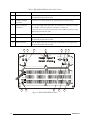
1
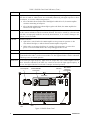
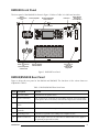
MICOM RM500/RM500R
500W HF-SSB Rack-Mount
Continuous Duty Transceivers
Owner’s Guide
Table of Contents
Introduction................................................................................................................... 1
Description .................................................................................................................... 2
General..................................................................................................................... 2
Equipment Versions .................................................................................................. 3
Main Features ........................................................................................................... 3
Major Accessories ..................................................................................................... 4
Performance Specifications ............................................................................................ 5
Main Technical Characteristics .................................................................................. 5
Accessories Connectors ............................................................................................. 6
Ordering Options...................................................................................................... 7
Familiarization with Equipment...................................................................................... 7
RM500 Front Panel ................................................................................................... 7
RM500R Front Panel................................................................................................. 9
RM500/RM500R Rear Panel ..................................................................................... 9
Equipment Installation ................................................................................................. 11
Installation Planning Guidelines............................................................................... 11
Preparations for Installation ..................................................................................... 12
Installation Procedure – Basic Radio ........................................................................ 13
Installation Procedure – Radio with PPS Option ...................................................... 13
Operation.................................................................................................................... 16
General................................................................................................................... 16
Preparations for Operation...................................................................................... 16
Operating Instructions ............................................................................................. 16
Bypassing the 500W Amplifier Section .................................................................... 16
Introduction
The MICOM RM500 (ordering option G160) and RM500R (ordering option G179) are 500W HF-SSB
rack-mount continuous duty transceivers, part of the MICOM-3 line of HF-SSB radio sets.
This manual covers the installation and operation of the RM500/RM500R transceivers. The manual
covers only procedures specific to the RM500 and RM500R; the other procedures, which are
common to the whole MICOM-3 product line, are described in the “Owner’s Guide,
MICOM-3E/3T/3R HF-SSB Transceivers”, Publication 6886867J01, and in the other applicable
MICOM-3 Supplements that cover optional features.
6888882V03
1
Description
General
The MICOM RM500 and RM500R are 500W HF-SSB continuous duty radio sets. Figure 1 shows a
general view of a typical 500W transceiver (the RM500R).
F1
F2
F3
F4
*
0
Figure 1. RM500R, General View
RM500 and RM500R expand the MICOM-3 product line by offering higher transmit power and thus
longer reach, and improved communications under bad propagation conditions and/or strong
interference.
An RM500 or RM500R radio set consists of a standard MICOM-3 transceiver tightly integrated with a
500W RF power amplifier and a 110/220 VAC, 50/60 Hz AC-powered power supply, all contained
within a compact chassis suitable for installation in 19 in. racks and shelves. The AC input voltage
range is automatically switched between 110 and 220 VAC, and therefore the equipment can be
used in the United States of America as well as in other countries.
Internal cooling fans enable operation over a wide range of temperatures, for continuous-duty data
transmission. The radio has multiple accessories connectors, for system interconnections.
For operation in multiple-transmitter or split sites, the RM500 and RM500R can be ordered with an
interface for the Pre-Selector/Post-Selector (PPS) (option G65).
Note
The G65 option does not include the Pre-Selector/Post-Selector (PPS) unit,
which must be separately ordered.
The RM500/RM500R transceiver is very well suited for base station applications, and can be directly
connected to a wide range of broadband or tuned antennas, including whip, dipole, traveling wave,
delta, and semi-delta antennas.
To obtain maximum forward power, a low VSWR antenna system should be used; however, in case of
excessive VSWR protection circuits prevent damage by reducing the transmit power to safe values.
2
6888882V03
Thus, the RM500 and RM500R will always attempt to transmit at the maximum safe power, even in
case of mismatch.
Special circuits protect the RM500 and RM500R against overheating and various types of
malfunctions. In case a critical problem is detected, the protection circuits are activated and bypass
the internal 500W power amplifier: in this case, the MICOM-3 transceiver is directly connected to
the antenna. This enables normal reception, as well as transmission, albeit at the lower power levels
(up to 125W) the MICOM-3 transceiver can provide. Front panel indicators indicate the type of
problem that has been detected, to help the operator correct it.
Being part of the MICOM-3 line, RM500 and RM500R offer similar capabilities and characteristics
and use common operating procedures, thereby enabling personnel familiar with the operation of
MICOM-3 equipment to start using the RM500/RM500R with minimal training.
Equipment Versions
MICOM-RM500
MICOM-3
A
3 FE
J
6ON
Esc
8 VU
T
9ZWX
Y
ALARM
0
#
?
F1
MICOM RM500
1/ @ 2 CB
G
F2
4 IH
5 LK
F3
7S QR
P
F4
*
D
M
MEN U
P
GPS
VOLT
OVER DR
FAILURE
TX
TEMP
VSWR
BYPASS
BAND
OUT
Transceiver for long range wireless voice,
fax, data and email communications.
USB
MICOM-RM500R
MICOM-3
F1
F2
F3
F4
Ruggedized transceiver with military
handset and connectors, for applications
requiring the utmost dependability and
reliability.
A
3 FE
G
5 LK
J
6ON
M
P
P
7S QR
8
T
U
V
YW
X
Z
ALARM
*
0
?
MICOM RM500R
1/ @ 2 CB
4 IH
D
9
MEN U
Esc
GPS
VOLT
OVER DR
FAILURE
TX
TEMP
VSWR
BYPASS
BAND
OUT
#
COM
USB
AUDIO
Main Features
•
Automatic Link Establishment per FED-1045 & MIL-STD-188-141B (JITC certified)
•
ISB (Independent Side Band) ready
•
Full interoperability with other manufacturers' radios complying with the same ALE standards.
Voice that's loud & clear
•
Built-in voice quality system utilizes proprietary algorithms to filter out background
noises, giving users exceptional communication clarity.
•
Selectable bandwidth allows fine tuning for optimal voice and data communications.
•
Voice-activated digital squelch.
6888882V03
3
User-friendliness
•
New control head features a large LCD, full-dot matrix digital display and an enhanced
keyboard for programming and set-up.
•
Radio operation can be executed using any standard USB keyboard.
•
Multiple language display available.
•
Transceiver can be controlled using PC and programming application.
•
Remote control configuration, allows the transceiver to be operated from a remote
location (at a distance of up to 5 km) using the optional 2-wire remote control head.
Years of trouble-free, most advanced communications
•
Upgrading to future technologies is easily done by installing new software into the
transceiver's DSP unit.
•
Easily replaceable digital components ensure cost-effective maintenance.
•
Very high MTBF, as with all MICOM radios.
•
Unique Built-In self Test (BIT) system provides exceptional dependability.
•
Protection circuits enable transmission at maximum safe power
Comprehensive communication and networking services
•
Office-quality communication services integrating fax, e-mail and data transmission and
reception.
•
MultiNet option, enables integration of different HF radio networks into one seamless
network, allowing excellent coordination between different operational nets.
•
AMD (Automatic Message Display) for free and pre-set text messages.
A proven family of radio products
•
RM500 and RM500R are members of the MICOM transceiver family – fixed and mobile
stations – covering the long-range wireless communication needs of thousands of
organizations worldwide.
Major Accessories
4
•
Automatic telephone interconnect
•
Antenna system
•
Pre/Post-Selector (PPS)
•
FM to HF repeater
•
HF modems
•
ATUs
•
Antennas and grounding kit
•
Secure voice and data
•
Vocoder
6888882V03
Performance Specifications
Main Technical Characteristics
This section presents the main technical characteristics of the RM500 and RM500R. For a listing of
the additional performance specs, refer to the “Owner’s Guide, MICOM-3E/3T/3R HF-SSB
Transceivers”, Publication 6886867J01, and to the applicable MICOM-3 Supplements that cover the
optional features available on your radio set.
Models
General
RM500
M91AMN0KV5-K (option G160)
RM500R
M95AMN0KV5-K (option G179)
Number of channels
200
Transmission frequency range
1.6 to 30 MHz
Transmit power (PEP and average) User-selectable levels:
•
Max:
500 W
•
High:
400 W
•
Medium: 250 W
•
Low:
200 W
Reception frequency range
100 kHz to 30 MHz
Sensitivity (SINAD)
0.3 µV for 10 dB SINAD
Audio bandwidth
350 to 2700 Hz
Data bandwidth
300 to 3300 Hz
Frequency stability
0.6 ppm (0.1 ppm optional)
Frequency resolution
10 Hz
Number of accessories connectors 4 (see Table 1)
Dimensions
6888882V03
Operating voltage
110 /220 VAC, 50/60 Hz, with automatic
switching
Power requirements
Max. 2000W
Operating temperature range
-10°C to +60°C/14°F to +140°F
Humidity
Up to 95%, relative humidity @ 50°C/122°F
Height
290 mm/11.42 inch
Width
480 mm/18.9 inch
Depth
550 mm/21.7 inch
Weight
32 kg/70.6 lbs
5
Accessories Connectors
The functions of the 25-pin accessories connectors, ACC-J1 to ACC-J4, are listed in Table 1. The
connectors include PTT and CW control lines, audio and baseband lines for external equipment,
auxiliary power output, serial RS-232 asynchronous data interfaces, and additional dedicated
handshaking and control lines. The functions supported by the serial data interfaces are determined
by the RM500/RM500R software.
Table 1. 25-Pin Accessories Connector, Pin Functions
Pin
6
Designation
Description
1
SPKR-
Differential output to the external 8Ω, 8W speaker
2
EXT RX DATA-
Baseband output (0 dBm, 600 Ω)
3
SPKR+
Differential output to the external 8Ω, 8W speaker
4
EXT RX AUDIO+
5
EXT RX AUDIO-
Differential received audio output (0 dBm, 600Ω; not controlled by volume, but
affected by squelch)
6
EXT TX AUDIO+
7
EXT TX AUDIO-
Differential transmit audio input (600Ω input impedance; 0 dBm is required for
full power)
8
PTT IN VOICE
Transmission command (short to ground) for voice signals
9
PTT IN DATA
Transmission command (short to ground) for data signals
10
PTT IN CW
Transmission command (short to ground) for CW (Morse) signals
11
SW A+
Primary DC voltage current limited output (max 1A)
12
DSI/KW C C
BDM – Data serial in/external RF amplifier channel change
13
KW ON/OFF
External RF amplifier power on/off output
14
EXT RX DATA+ *
Baseband output (0 dBm, 600 Ω)
15
RXA
Receive input (point-to-point protocol to host/HLC)
16
TXA
Transmit output (point-to-point protocol to host/HLC)
17
EX RESET
External RESET input (for BDM)
18
GND
Ground
19
KW PTT
PTT output to external RF amplifier
20
EXT ALARM
External alarm output (open collector, pulled to ground when external alarm is
activated)
21
VPP
Flash programming voltage, input to BDM
22
DSC/KW_ALC
BDM – Data serial clock/external RF amplifier ALC
23
SQ GATE
Squelch open/closed indication output
24
DSO/FAN ON/OFF
BDM – Data serial out/Fan control
25
FREEZE/KW TU
BDM – Freeze/external RF amplifier tune
6888882V03
RM500/RM500R
Main Options
•
USB port for external keyboard
•
PC control and programming software package
•
ALE DTM/DBM
•
PPS interface
•
Interface for VP-116 voice privacy device
•
2-wire remote control head
Ordering Options
G424 (FVN4841)
Add
PC control and programming software package
S809 (FLN2515)
Enhanced
Interface cable kit for CW key & headphones
G112
Enhanced
High frequency stability option (0.1 ppm)
G849
Add
Interface option for external secure voice device (VP-116)
G419
Enhanced
USB COM port for connecting external keyboard
G423
Add
ALE DTM/DBM (data transfer message/data block message)
S308 (FLN2517)
Add
Interface cable kit for phone patch
G561 (FLN2530)
Add
Interface cable for MICOM link unit
G65
Add
Interface for pre-post selector for co-site or split-site application
G420
Add
2-wire remote control head (up to 5 km)
Familiarization with Equipment
RM500 Front Panel
The front panel of the RM500 includes a standard MICOM-3 control panel, and the additional items
identified in Figure 2.
For a description of the MICOM-3 control panel, refer to the “Owner’s Guide, MICOM-3E/3T/3R
HF-SSB Transceivers”, Publication 6886867J01; for indicator functions, refer to Table 2.
Table 2. RM500 Front Panel Indicators
Indicator
Function
VOLT
Power supply fault indicator: lights when an internal supply voltage is out of limits. In this case,
the 500W amplifier section cannot operate
OVER DR
Input overload indicator: lights when the RF drive power supplied to the 500W amplifier is too
high. The 500W amplifier section is bypassed
6888882V03
7
Table 2. RM500 Front Panel Indicators (Cont.)
Indicator
TEMP
Function
Amplifier overheat indicator: lights when the internal temperature is too high. Usually, this occurs
when the air intake or exhaust vents are accidentally obstructed, prolonged exposure to direct
sun radiation, or excessive ambient temperatures.
• If the FAILURE indicator flashes while TEMP lights but BYPASS is off, the 500W amplifier
continues transmitting at half power
• If the FAILURE and BYPASS indicators light together with TEMP, the 500W amplifier has
switched to the bypass mode
VSWR
Excessive VSWR indicator: lights when the 500W amplifier is in the transmit mode to indicate
that the antenna VSWR exceeds the maximum allowed. This may be caused by a disconnected
feed cable, an improperly installed or incorrectly tuned antenna, or as a result of damage to the
antenna or to its feed cable
FAILURE
PA failure indicator:
•
Lights when a critical fault in the 500W amplifier section prevents its operation. In this
case, BYPASS also lights, to indicate that the 500W amplifier is bypassed
•
Flashes when an operational problem, for example, high temperature, excessive drive
power or excessive VSWR activates the corresponding protection circuits
TX
Transmission mode indicator: lights when the 500W amplifier operates in the transmit mode
BYPASS
Bypass mode indicator: lights when the 500W amplifier is bypassed. The amplifier is normally
bypassed when the radio is in the receive mode. It is also bypassed when a fault or abnormal
condition prevents its normal operation
BAND OUT Out-of-band input signal frequency: lights when the output filter of the 500W amplifier (used to
reduce harmonics radiated by the radio set), cannot be tuned to the input signal frequency. In
this case, the highest filter band is selected to attempt continued operation
Internal Speaker
Standard MICOM-3
Control Panel
Indicators
Main ON/OFF
Switch and
Circuit Breaker
MICOM-RM500
MICOM-3
?
F1
A
3 FE
J
6ON
Esc
T
Y
ALARM
1/ @ 2 CB
D
M
G
5 LK
P
8 VU 9ZWX
F2
4 IH
F3
7S QR
F4
*
0
MENU
P
GPS
#
VOLT
OVER DR
TEMP
VSWR
FAILURE
TX
BYPASS
BAND
OUT
USB
Headphone
Jack
Telegraphy Key
Jack
Figure 2. RM500 Front Panel
8
6888882V03
RM500R Front Panel
The front panel of the RM500R is shown in Figure 3. Refer to Table 2 for indicator functions.
Serial
Communication
Port
Internal Speaker
Standard MICOM-3
Control Panel
Indicators
Main ON/OFF
Switch and
Circuit Breaker
MICOM-RM500R
MICOM-3
F1
?
A
D
G
H
I
5
J
K
L
M
N
O
P
8 VU 9ZWX
1/ @ 2 CB 3 FE
F2
4
F3
7S QR
F4
*
T
0
MENU
P
6
Y
Esc
ALARM
GPS
VOLT
OVER DR
TEMP
VSWR
#
FAILURE
TX
BYPASS
BAND
OUT
COM
USB
AUDIO
Audio Connectors
for
External Speaker
and Handset
Internal Speaker
ON/OFF Switch
Connector for
Optional
External USB
Keyboard
Figure 3. RM500R Front Panel
RM500/RM500R Rear Panel
Figure 4 shows the rear panel of the RM500 and RM500R. The functions of the various items are
explained in Table 3.
Table 3. RM500/RM500R Rear Panel Items
Item Description
Function
1
AC Power Cable
Connection to AC power source
2
RF OUT Connector
UHF connector for connection of feed cable to antenna. Serves as the radio
set RF input in the receive mode, and as the RF output in the transmit mode
3
REMOTE CONTROL
Switch
Enables/disables remote control by the optional 2-wire control head
4
REMOTE CONTROL
Terminals
Connection of 2-wire line to optional 2-wire control head
5
Grounding Screw
Connection of ground to the 500W power amplifier section
6
RX OUT Connector
BNC RF output connector, for connection of unfiltered RF receive signal to
the optional pre/post-selector (PPS)
6888882V03
9
Table 3. RM500/RM500R Rear Panel Items (Cont.)
Item Description
Function
7
TX OUT Connector
BNC RF output connector, for connection of unfiltered RF transmit signal to
the optional pre/post-selector (PPS)
8
TUNER CONTROL
Connector
Connection of control signals to the optional pre/post-selector (PPS)
9
ACC-J1 to ACC-J4
Connectors
Four 25-pin D-type male connectors, for connection to external accessories,
for example, voice privacy devices, modems, vocoders, etc.
Connector ACC-J2 is used for connection to the parallel I/O interface of the
optional pre/post-selector (PPS)
10
Grounding Screw
Connection of ground to the transceiver section
11
TX IN Connector
BNC RF input connector, for connection of filtered RF transmit signal from
the optional pre/post-selector (PPS)
12
RX IN Connector
BNC RF input connector, for connection of filtered RF receive signal from
the optional pre/post-selector (PPS)
12
RX IN
11
9
10
8
ACC-J1
ACC-J3
ACC-J2
ACC-J4
TX IN
TUNER CONTROL
7
6
TX OUT RX OUT
REMOTE CONTROL
110/220VAC
RF OUT
1
2
3
4
5
Figure 4. RM500/RM500R Rear Panel
10
6888882V03
Equipment Installation
Warning
For general operating and installation safety information, see the
“Owner’s Guide, MICOM-3E/3T/3R HF-SSB Transceivers”, Publication
6886867J01.
During installation work, strictly observe the applicable safety precautions
and local regulations. Do not work on the antenna system during
lightning storms.
Proper grounding is essential for your safety, and for good
communication performance.
Warning
Do not touch the antenna and the RF connectors while the
RM500/RM500R operates. During transmission, high RF voltages appear
at the RF connectors, the antenna cables, and on the antenna itself. These
voltages may cause severe injury or death on contact.
Make sure the antenna is not located near high-voltage lines.
All personnel must be familiar with the applicable safety requirements
before attempting to install or operate the RM500/RM500R. Severe injury
or death could result from failure to comply with the safety practices.
Caution
The RM500/RM500R is a two-person lift. Make sure that help is available
during the installation activities.
Installation Planning Guidelines
This section provides information necessary for planning the installation of RM500/RM500R.
Grounding
Failure to provide proper grounding will degrade system operation and cause RF voltage to be present
on the equipment chassis. A possible serious hazard to personnel could result, as well as equipment
malfunction.
Wide copper straps, as short as possible, must be used for grounding. These straps must be clamped
or bonded to a reliable, low-resistance grounding system.
Power Requirements
The RM500/RM500R requires AC power at a nominal voltage of 110 or 220 VAC, 50/60 Hz. The
RM500/RM500R will automatically select the appropriate voltage range. The AC power consumption
during high-power transmission is up to 2 kW.
A suitably rated circuit breaker must be used to protect the supply line to the RM500/RM500R. It
must also enable disconnection of supply voltage during installation and maintenance.
6888882V03
11
Cooling
RM500/RM500R units are cooled by internal fans. Air is taken in through the front panel vent, and
discharged toward the rear. Therefore, make sure that sufficient free space is available around the
equipment to enable free air flow.
Do not stack equipment units: leave at least 1U free above and below the RM500/RM500R.
Installation Data
The RM500/RM500R are intended for installation in 19 in. racks. The equipment has front-mounted
brackets for attachment. To provide convenient access during maintenance, the RM500/RM500R
may be installed in a sliding drawer or on slides capable of supporting the equipment weight.
Make sure that sufficient rack space is available for installation of other options, for example, the
1U-high PreSelector/PostSelector (PPS).
The rack must be connected to a reliable, low-resistance grounding system.
Sufficient front and rear clearance is required to permit convenient access to front and rear panels, as
well as for removal and installation of equipment units, connection of cables, and maintenance.
Antenna System
Antenna systems are selected in accordance with the specific communication requirements of each
customer: many HF antenna types are available, each providing different radiation characteristics to
meet different communication requirements. Therefore, the selection and installation of an antenna
system is customer’s responsibility. If necessary, contact Mobat or your local Mobat representative for
additional information.
The antenna system must provide a matched termination at the operating frequency, and must be
capable of handling the maximum power output of the RM500/RM500R.
Antenna Feed System
The antenna feed system comprises any cables, panels and matrices, and any accessories that carry
HF signals between the RM500/RM500R and the antenna itself.
All the antenna feed system components, and in particular the feed cable, must have low loss and be
capable of carrying the maximum power output of the RM500/RM500R. Remember that any power
loss along the cable is signal loss!
To protect yourself and the radio equipment against lightning strokes and accidental contact of
antenna and/or feed cable with high voltage lines, a properly grounded coaxial protector must be
installed at the point of entry of the feed cable into the building or communication shelter. The
recommended protector type is IS-B50LN-C0 by PolyPhaser Corp. (also available from Mobat, as Cat.
No. 2072-09128-00).
Preparations for Installation
Before starting the installation of a new RM500/RM500R, review the installation plan and make the
following checks:
1. Identify the prescribed location of the equipment in the rack or cabinet, and check the
mounting surface, and the mounting holes. Thoroughly clean the mounting surface and
remove all paint, grease and dirt from the holes to provide a better grounding connection.
12
6888882V03
2. Check availability of AC power, and grounding arrangements.
3. Check antenna installation, in accordance with the antenna installation and operation manual.
4. Check the cable runs between the RM500/RM500R and the prescribed antenna, including the
coaxial protector. Make sure that the cables are securely fastened, and do not show signs of
external damage.
Note
Before installing the RM500/RM500R on slides, make sure you are familiar with
the procedures needed to install slides in the rack/cabinet, and to safely install
heavy equipment on the slides.
Installation Procedure – Basic Radio
1. Identify the installation position of the RM500/RM500R in the rack.
2. Install the RM500/RM500R in the prescribed installation position, fastening it by means of four
screws to the rack rails or to the drawer front.
3. Connect grounding straps from each of the two RM500/RM500R grounding screws (located on
its rear panel), to the prescribed cabinet’s grounding bar.
4. Set the power switch on the RM500/RM500R front panel to OFF (down position).
5. Connect cables to the unit as follows:
•
Connect the RM500/RM500R AC power cable to the prescribed outlet on the power
distribution box of the cabinet.
•
Connect the antenna feed cable to the RF OUT connector of the RM500/RM500R.
•
When an external device is used, connect the prescribed cable to the accessories
connector of the RM500/RM500R that supports the corresponding device.
6. Connect audio accessories to the front panel connectors.
Installation Procedure – Radio with PPS Option
PPS Functions
The optional Preselector/Postselector, PPS-100 (referred to as PPS in this manual), supported as an
option by the RM500/RM500R, permits operation of collocated receivers and transmitters on
frequencies separated by as little as 10%. The PPS operating frequency range is 1.60 to 29.99 MHz.
To use the PPS, order the RM500/RM500R with option G65. The connections between an
RM500/RM500R with option G65 and the PPS are shown in Figure 5.
When the G65 option is installed, the PPS is controlled by the RM500/RM500R through serial and
parallel ports and is automatically inserted by the RM500/RM500R in the signal path in accordance
with the operating mode:
•
In the receive mode, the PPS functions as a preselector, providing an additional front
end selectivity stage for the receive path of the RM500/RM500R. This reduces the
receiver desensitization and overload that would normally occur in the presence of
strong adjacent RF transmissions.
6888882V03
13
•
In the transmit mode, the PPS is used as a postselector. It attenuates spurious signals and
broadband noise in the driver transmit signal before it reaches the internal 500W power
amplifier, thereby reducing interference to neighbouring receivers.
In both modes, the PPS automatically tracks the RM500/RM500R operating frequency. Rapid tuning
makes the PPS suitable for Automatic Link Establishment (ALE) or Adaptive Applications.
During self-test, the PPS automatically switches to the bypass mode: in this mode, RF signals pass
directly through the PPS, without filtering, and therefore does not interfere with system operation.
The PPS also switches to the bypass mode when the RM500/RM500R frequency is outside the PPS
operating range, 1.60 to 29.99 MHz.
In case excessive RF power is applied to the PPS, the PPS enters the RF overload protection mode: in
this mode, the PPS antenna port is disconnected, and the internal antenna input is short-circuited to
ground. This also protects the RM500/RM500R internal transceiver against overload.
The PPS is housed in a 1U high (1.75 in.) case intended for 19 in. rack mounting. Standard operation
is from 115 or 230 VAC, 50/60 Hz, and can also be powered from 12 or 24 VDC DC sources.
PPS Installation Procedure
Note
The following procedure assumes that the basic RM500/RM500R unit has already
been installed, as explained above (page 13).
1. Identify the installation position of the PPS in the rack, and the position of the
RM500/RM500R to which it will be connected.
2. Install the PPS in the prescribed installation position, fastening it by means of four screws to the
rack rails or to the drawer front.
3. Connect a grounding strap from the RM500/RM500R grounding screw to the prescribed
cabinet’s grounding bar.
4. Set the power switches on the RM500/RM500R and PPS front panels to OFF (down position).
5. Connect the PPS AC power cable to the prescribed outlet on the power distribution box of the
cabinet.
6. Refer to Figure 5 and connect cables between RM500/RM500R and the PPS as follows:
RM500/RM500R Connector
PPS Connector
TUNER CONTROL
SERIAL I/O
ACC-J2
PARALLEL I/O
RX IN
ANTENNA
TX IN
EXEC OUT
TX OUT
PA IN
RX OUT
RADIO
This completes the installation of the PPS.
14
6888882V03
PARALLEL I/O
DC IN
SERIAL I/O
+12/24 VDC
ANTENNA
EXC OUT
PA IN
AC POWER
GND
RADIO
Serial
Control Cable
Parallel
Control Cable
RX IN
ACC-J1
ACC-J3
ACC-J2
ACC-J4
TX IN
TUNER CONTROL
TX OUT RX OUT
REMOTE CONTROL
110/220VAC
RF OUT
To Antenna
Figure 5. Connections to Optional PPS
6888882V03
15
Operation
General
The following instructions present operating procedures specific to the RM500 and RM500R. It is
assumed that the operator is familiar with the common MICOM-3 operating procedures; if necessary,
refer to the “Owner’s Guide, MICOM-3E/3T/3R HF-SSB Transceivers”, Publication 6886867J01, and
to the applicable MICOM-3 Supplements that cover optional features.
Preparations for Operation
1. Set the REMOTE CONTROL switch on the rear panel of the RM500/RM500R to the OFF
(down) position.
2. For the RM500R, set the internal speaker switch to ON (up).
Operating Instructions
1. Turn the radio on by setting its main switch to ON (up).
2. Adjust the volume control to a comfortable listening level.
3. You are now ready to start using the RM500/RM500R. For operating procedures, you may use
the information appearing in the “Owner’s Guide, MICOM-3E/3T/3R HF-SSB Transceivers”,
Publication 6886867J01.
4. To turn the radio off, set its main switch to OFF (down).
Bypassing the 500W Amplifier Section
The internal 500W amplifier section of the RM500/RM500R can be permanently bypassed. In this
case, you can still transmit at a power of up to 125W using the capabilities of the MICOM-3
transceiver which is part of the RM500/RM500R.
You can bypass the 500W amplifier section in case the full transmit power of the RM500/RM500R is
not needed (for example, good communication conditions), to save power (the maximum power
consumption then decreases to approx. 500W), or when a technical problem in the 500W amplifier
section prevents its operation.
To bypass the 500W amplifier section, select NONE on the PROG>RAD>OPTS>ACC menu.
16
6888882V03