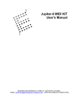
1
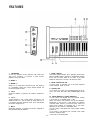
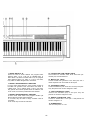
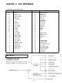
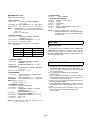
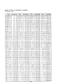
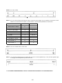
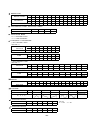
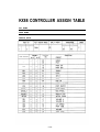
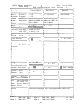
YAMAHA
AUTHORIZED
PRODUCT MANUAL
MIDI MASTER KEYBOARD
YAMAHA
MIDI MASTER KEYBOARD
OWNER'S MANUAL
ABOUT THIS MANUAL
CONTENTS
We would like to take this opportunity to thank you for
purchasing the Yamaha KX88 MIDI Master keyboard. The
KX88 puts you in complete control of all MIDI devices,
both those presently on the market and those yet to come.
In order to take full advantage of the KX88, please read
this manual carefully.
This manual is divided into three chapters.
1. A guided tour of the KX88.
2. A detailed, systematic explanation of the KX88.
3. Charts and tables. Reference material.
The best way to understand something like the KX88 is to
use it, so rather than tell you everything about the KX88,
first we’re going to show you how to play it, and then
begin explaining about it’s incredibly wide possibilities.
So, we recommend that you go through this manual in
order and try all the examples.
-1-
ABOUT THIS MANUAL . . . . . . . . . . . . . . . . . . . .
DESCRIPTION . . . . . . . . . . . . . . . . . . . . . . . . . .
PRECAUTIONS. . . . . . . . . . . . . . . . . . . . . . . . . .
FEATURES . . . . . . . . . . . . . . . . . . . . . . . . . . . .
CONNECTIONS. . . . . . . . . . . . . . . . . . . . . . . . . .
1
2
2
3
5
CHAPTER 1: LET’S PLAY THE KX88 . . . . . . . . . .
IMPORTANT NOTE . . . . . . . . . . . . . . . . . . . . .
THREEMODES . . . . . . . . . . . . . . . . . . . . . . . .
PLAY MODE . . . . . . . . . . . . . . . . . . . . . . . . . .
6
6
7
7
CHAPTER 2: FUNCTIONS OF THE KX88. . . . . . . .
SUMMARY OF THE KX88 . . . . . . . . . . . . . . . .
FUNCTIONS OF THE KX88 . . . . . . . . . . . . . . .
PLAY MODE . . . . . . . . . . . . . . . . . . . . . . . .
CA MODE . . . . . . . . . . . . . . . . . . . . . . . . . .
INTERNAL FUNCTIONS . . . . . . . . . . . . . . . .
PA MODE . . . . . . . . . . . . . . . . . . . . . . . .
SPECIAL FUNCTIONS . . . . . . . . . . . . . . . . .
PRECAUTIONS WHEN USING THE KX88 WITH
THE DX7.. . . . . . . . . . . . . . . . . . . . . . . .
9
9
9
9
9
10
11
12
CHAPTER 3: SETTING UP THE KX88 . . . . . . .
CA MODE . . . . . . . . . . . . . . . . . . . . . . . . .
OTHER FUNCTIONS IN CA MODE . . . . . .
PA MODE . . . . . . . . . . . . . . . . . . . . . . . . . . . .
FUTURE USES OF PA MODE . . . . . . . . . . . . .
CONTROL CHANGE . . . . . . . . . . . . . . . . . . .
PARAMETER CHANGE . . . . . . . . . . . . . . . . .
UNIVERSAL PARAMETER . . . . . . . . . . . . . .
OTHER PA MODE FUNCTIONS . . . . . . . . . . .
KX88 BLOCK DIAGRAM . . . . . . . . . . . . . . . . .
SPECIFICATIONS . . . . . . . . . . . . . . . . . . . . . .
13
13
16
17
17
17
18
20
20
21
22
CHAPTER 4: FOR REFERENCE . . . . . . . . . . . . . .
CONTROLLER CODE PRESET TABLE . . . . . . .
MIDI OUTPUT . . . . . . . . . . . . . . . . . . . . . . . .
MIDI INPUT . . . . . . . . . . . . . . . . . . . . . . . . . .
OTHER SPECIFICATIONS . . . . . . . . . . . . . . . .
BINARY, DECIMAL AND HEXADECIMAL
CONVERSION . . . . . . . . . . . . . . . . . . . . . . . .
CHANNEL VOICE MESSAGE . . . . . . . . . . . . . .
DX SERIES PARAMETER CHANGE . . . . . . . . .
KX88 CONTROLLER ASSIGN TABLE . . . . . . . .
MIDI IMPLEMENTATION CHART . . . . . . . . . . .
FCC CERTIFICATION . . . . . . . . . . . . . . . . . . .
23
23
23
24
24
12
25
26
28
32
33
34
DESCRIPTION
The Yamaha KX88 is an 88 key, weighted action MIDI
keyboard and control center for all MIDI equipped instruments and devices. It is the first completely programmable
and assignable MIDI keyboard. Each of the controllers
(pitch and modulation wheels, after touch, breath controller, 2 foot controllers, 2 foot switches, 4 front panel sliders
and 7 front panel buttons) may be programmed to send any
type of MIDI information.
Also, the keyboard may be used in one of three modes
Single: All key on/off signals are sent on one MIDI channel.
Dual: All key on/off signals are sent simultaneously on
two MIDI channels.
Split: The keyboard may be split at any selected point,
and upper and lower sections sent on different MIDI
channels.
The keyboard may be transposed up or down in halfsteps, to a maximum of ±2 octaves. In split mode, the
upper and lower sections may be transposed independently.
All settings (keyboard mode, MIDI channel, transpose and
controller assignment) may be stored in one of 16 memory
banks, and recalled by any specified controller.
PRECAUTIONS
CLEANlNG
Use only a mild detergent on a cloth, and dry with a soft
cloth. Never use solvents (such as benzine or thinner)
since they can melt or discolor the instrument.
ELECTRICAL STORMS (LIGHTNING)
Computer circuitry, including that in the KX88, is sensitive
to voltage spikes. For this reason, the DX7 should be
turned off and unplugged from the AC receptacle in the
event of an electrical storm. This precaution will avoid the
chance that a high voltage spike caused by lightning will
damage the instrument.
ELECTRO-MAGNETIC FIELDS
Computer circuitry is also sensitive to electromagnetic
radiation. Television sets, as well as radio receivers, transmitters and transceivers, and wireless microphone or
intercom systems are all potential sources of such radiation,
and should be.
LOCATION
Avoid placing the KX88 in direct sunlight or close to a
source of heat. Also, avoid locations in which the instrument is likely to be subjected to vibration, excessive dust,
cold or moisture.
HANDLING
Avoid applying excessive force to the slide knobs, dropping
or rough handling. While the internal circuitry is of reliable,
integrated circuit design, the KX88 is nonetheless a fine
instrument that should be treated with care.
POWER CORD
Always grip the plug directly when removing it from
an AC receptacle. Removing the plug from the AC receptacle
by pulling the cord can result in damage to the cord, and
possibly a short circuit. It is also a good idea to disconnect
the KX88 from the AC receptacle if you don’t plan to use
the instrument for an extended period of time.
-2-
FEATURES
7. MODE SWITCH
This switch selects between the 3 operation modes. Each
time the MODE switch is pressed, it will alternate between
PLAY and CA mode. While in CA mode, if you press
MODE for more than 1 second, it will enter PA mode.
1. KEYBOARD
An 88 key weighted action keyboard with initial and
after touch sensitivity. It functions in three modes;
SINGLE, DUAL and SPLIT.
2. WHEEL 1
8. MODE INDICATOR LED
In PLAY mode, it indicates one of the three keyboard
modes; SINGLE, DUAL or SPLIT.
3. WHEEL 2
Wheel 1 is a center-return pitch-bend type, and Wheel 2
is a modulation wheel type. These wheels perform the
functions assigned to them.
9. ASSIGN LED
In CA mode, the upper LED (CONTROLLER) will be lit,
and in PA mode, the lower LED (PARAMETER) will be
lit.
4. CSI-4
Continuous Sliders 1-4 perform the functions assigned to
them.
5. TS1,2
Toggle Switches 1 and 2 each perform 2 functions, one
when the LED is on, and one when off. Each time TS1 or
2 is pressed, the LED alternates on/off, and it will perform
the function assigned to it.
6. MS1-5
Momentary Switches 1-5 perform the function assigned to
them each time they are pressed.
-3-
10. UPPER READOUT, LOWER READOUT
In PLAY mode, this displays the voice program number
1-32 for bank A. (In 8 BANK mode, 1-128)
When CA mode is first entered, CA will be displayed.
Depending on the function, it will display the selected
controller, MIDI channel or transpose point. When PA
mode is first entered, it will display PA. In PA mode,
depending on the function, it will display data.
In PLAY mode, it will display the voice program number
for bank B.
In CA mode, it will display the controller code, MIDI
channel or transpose point.
In PA mode, it will display data.
11. BANK SWITCH A, B
These are used to chose whether the program select
switches select 1-16 or 17-32. (Or in 8 BANK mode, to
select banks 1-8) When the bank LED is off, the program
select switches select 1-16; when on, 17-32. In CA mode,
they enable or disable assignments to each bank.
14. CONTROLLER CODE PRESET TABLE
The functions for controller codes 00-3F have been permanently set, and are listed here.
15. MIDI IN, OUT JACKS
Connect a MIDI tone generator to the OUT jack, and a
remote keyboard such as the KX5 to the IN jack.
12. BANK A PROGRAM SELECT SWITCHES
In PLAY mode, these select the voice program number of
the MIDI tone generator units connected to the KX88. In
2 Bank mode, 1-32. In 8 Bank mode, 7-128. In CA mode,
they perform the functions printed above the switches, and
in PA mode, the functions printed below the switches.
16. FOOTSWITCH JACKS
Connect footswitches (such as the FC4 or FC5) to this jack.
They will perform the function assigned to them.
17. FOOT CONTROLLER JACKS
Connect foot controllers (FC7) to this jack. They will
perform the functions assigned to them.
13. BANK B PROGRAM SELECT SWITCHES
In PLAY mode, these select voice program numbers just
like the Bank A Program Select Switches:
In CA mode, they are used to assign controller codes to
controllers.
In PA mode, they are used to enter data.
18. BREATH CONTROLLER JACK
Connect a Yamaha BC1 to this jack. It will perform the
function assigned to it.
19. POWER SWITCH
This turns the power on or off.
-4-
CONNECTIONS
The KX88 will not produce sound by itself. Please connect
it with a MIDI cable to a MIDI tone generator such as the
TX816, or to a MIDI synthesizer such as the DX7. You will
need at least one MIDI tone generator or synthesizer, and
to take advantage of the split and dual modes, two or more
are necessary. To make full use of the KX88’s possibilities,
we suggest that you connect the optional footswitches and
foot controllers.
NOTE: Use only the new Yamaha FC7. The FC3A will
not function with the KX88.
NOTE: For DX users; Set SYS INFO AVAIL, so that the
DX will accept parameter change messages.
-5-
CHAPTER 1: LET'S PLAY THE KX88
IMPORTANT NOTE
This part of the manuaL is a step-by-step introduction to the
KX88. It assumes that the KX88 is still as it was preset at
the factory. (ie. the same standard setting in all memory
banks) If not, please initialize the memory by turning the
power on while holding down the bank A and bank B
switches. Doing this will set all code memories 1 - 1 6 to the
same initial setting on page 6.
If you or someone else has already stored settings in the
KX88, and you don't want to erase everything, select a
Code Memory that you know has the original settings. (See
page 10 for selecting a code memory.)
•
INITIALIZE MEMORY
B A N K A....... .
BANK B ........
SPLIT POINT .. . .
BANK . . . . . . . . .
TRANSPOSE.....
Check that all connections are correctly made as shown on
page 5, and that the MIDI reception channel of the tone
generator or synthesizer is set to 1 or 2. If you have two or
more tone generators, set one to receive MIDI channel 1,
and the other to receive MIDI channel 2. Turn the KX88
power switch ON. Now try playing a note on the KX88.
MIDI CH1
MIDI CH2
C3
2 BANK
BANK A = C3
BANK B = C3
The tone generator should make sound. (If there is no
sound, recheck the connections and make sure that the
volume of the mixer or amp is up. Whatever note you play,
both tone generators should sound. (Dual Key Assign sends
each note on both MIDI banks.)
-6-
n
THREE MODES
SELECTING VOICE PROGRAMS
In PLAY mode, the two readouts will show the voice numbers for each MIDI bank. Select voices using the Bank
switch and program select switches 1-16. To select voices
17-32, press the Bank switch. The Bank LED will light, and
switches 1-16 will now select voices 17-32. To go back to
1-16, press the Bank switch again. In this way, you can
select voices independently for MlDI banks A and B.
The KX88 has three basic modes, and the selector switches
have different functions in these different modes. Change
modes by pressing the MODE switch. Pressing the MODE
switch will take you back and forth between PLAY and
CA modes. If you hold the MODE switch down for about 1
second while in CA mode, you will enter PA mode. Pressing
MODE again will return you to PLAY mode.
NOTE: The Yamaha DX7 and TX816 voice program memories are 1-32. However, some MIDI synthesizers
and tone generator units may have up to 128 voice
program memories. The KX88 may be set to 8
BANK mode to select voice programs 1-128. See
p. 20.
ASSIGNABLE CONTROLLERS
Each of the KX88’s controllers (Wheels 1 and 2, Breath
Controller, After Touch, 4 Continuous Sliders, 5 Momentary Switches, 2 Toggle Switches, 2 Foot Controllers and
2 Foot Switches) may be assigned to perform any function
you want in PLAY mode. For example, you may have a
foot controller controlling pitch-bend, and a footswitch
switching between mono/poly, or switching MIDI channels.
Also, these functions may be assigned to affect MIDI banks
A and/or B. Your imagination is the only limit.
PLAY MODE
This is the mode in which you will normally play the KX88.
One of the 3 play mode indicators will be on, and the 2
readouts will show the voice program for MIDI banks A
and B.
The KX88 sends MIDI signals on two independent banks.
(As set up at the factory, these will be MIDI channels 1 and
2.) Notice that the PLAY mode LED is indicating DUAL.
This means that the whole keyboard is sending the same
MIDI signals on both MIDI banks A and B.
FACTORY PRESET CONTROLLER ASSIGNMENTS
For now, however, let’s learn to use the functions that were
assigned to the various controllers at the factory. (For a
complete list of how the KX88 is preset, see page 6.)
-7-
• SINGLE, DUAL AND SPLIT keyboard modes
• MONO/POLY Press TS1. (TS1 = MONO/POLY)
The TS1 LED indicator lights, and the sound generator is
now in MONO mode and will sound only the last note you
play. The TS1, 2 Toggle switches are of a different type
than the other front panel switches we have used so far.
TS1, 2 each have two functions, one when they are pressed
ON and one when they are pressed OFF. In this case, the
two assignments are TS1 = Mono, Poly.
First, press MS1. (This switch has been assigned to SINGLE,
from now on abbreviated to MS1 = SINGLE.) The keyboard
is now in SINGLE mode. Notice the LED is now indicating
SINGLE. This means that only one MIDI bank is active. If
you play the KX88 keyboard, sound will come from only
one tone generator module. Notice that only one of the
readouts is lit. This indicates which MIDI bank A or B is
being sent. To switch banks, press a program select or bank
switch in the other bank. If you press the bank switch of
the bank that is not being sent, that bank will now become
active, with the same voice program number it had before.
If you press a program select switch in the bank that is not
being sent, that bank will become active, and the voice program will change to the number you have just pressed.
PORTAMENTO ON/OFF, PORTAMENTO TIME,
LFO SPEED
Now press the other toggle switch, TS2.
(TS2 = Portamento ON, Portamento OFF) When the TS2
LED is on, portamento will apply to the keyboard. (Again,
all these settings can be applied to MIDI channels A and/or
B, as we will explain later on p. 14) If the portamento time
is too short, you will not be able to hear it. So, adjust the
portamento time. CS4 (continuous slider) has been assigned
to portamento time. (CS4 = portamento time) Move it up
and down to adjust the portamento time.
CS3 = LFO speed. Move it up and down to change the LFO
speed.
NOTE: LFO speed is a voice parameter, and the KX88 is
sending System Exclusive messages (Yamaha ID
number) to change them. If you are using other
companies’ tone generator units, you will have to
change these parameters by assigning a Universal
Parameter. (see page 20.)
CS1 and CS2 have been assigned to VOLUME for
banks A and B. Move them and notice how the
volume of each tone generator changes.
• Let’s try the other controllers.
WI = Pitch Bender, W2 = Mod Wheel, After Touch = After
Touch, Breath Controller = Breath Controller, FC1 = Volume, FC2 = Foot Controller, FS1 = Sustain switch, and
FS2 = Portamento switch. All of these will affect the MIDI
tone generator or synthesizer in the normal way. For example, if the DX7 function memory is set so that Foot
Controller Range is 99 and Foot Pitch is ON, then using the
FC2 connected to the KX88 will change the Pitch Modulation of the DX7.
If you press MS2, you will return to DUAL mode. (MS2 has
been preset to DUAL, ie. MS2 = DUAL) When you play the
keyboard, both tone generators will sound, since both MlDI
banks are active.
There is one more keyboard mode, SPLIT. Press MS3.
(MS3 = SPLIT) The LED will indicate SPLIT. In SPLIT
mode, notes played on or below the split point will be sent
on MIDI bank A, and notes played above the split point
will be sent on MIDI bank B. If you press MS3 again while
you are in SPLIT mode, the upper readout will show SP
and the lower readout will show the current split point.
C3 Touch the keyboard where you want the new split
point to be, and the new split point will be displayed. A
decimal point indicates a sharp. (#)
We have now finished our explanation of the way the KX88
has been set up at the factory. Before you go on to the next
chapter of this manual, spend some time becoming familiar
with the functions we have explained.
SWAP Press MS4. (MS4 = SWAP)
This will interchange MIDI banks A and B. Notice that the
voice program numbers in the readout have traded places.
Now, MIDI bank A is channel 2, and B is channel 1. If you
SWAP while in SPLIT mode, the sound that you were playing on the lower part of the keyboard will interchange with
the sound you were playing in the upper part.
MIDI CHANNEL Press MS5. (MS5 = MIDI CH)
The readouts will show the MIDI channel number for banks
A and B. (Later, we will learn how to change the channels.)
-8-
CHAPTER 2: FUNCTION OF THE KX88
n
SUMMARY OF THE KX88
n
CA MODE
OPERATION MODES
The KX88 has three modes of operation: PLAY mode, CA
mode, and PA mode.
You will normally play the KX88 in PLAY mode. When
you operate the various controllers while in this mode, the
MIDI data that has been assigned to the controllers will be
sent.
In CA mode, you may assign functions (controller codes
00-FF) to the various controllers.
In PA mode, you may define controller codes 40-FF to
be any desired MIDI information. Controller codes 00-3F
have been preset at the factory and cannot be changed.
Pressing MODE will take you back and forth between
PLAY and CA modes. To enter PA mode, press MODE for
about 1 second while in CA mode. Pressing MODE again
will take you back to PLAY mode.
In CA mode, the program select switches perform the
functions printed above them. Use the bank A program
select switches 1-10 to select controllers Wheel 1-Foot
controller 2. The bank switch LEDs indicate which bank
(A, B or both) this controller is active for. You may
enable/disable each bank by pressing its bank switch.
The upper readout will show which controller you have
selected. (see below)
MIDI CHANNEL
The KX88 sends MIDI channel messages on two channels
simultaneously. We will call these MIDI BANK A and B.
The channel number for each bank may be set independently.
FUNCTIONS OF THE KX88
PLAY MODE
When Wheel 1-2, Breath Controller, After touch, CS1-4,
Foot Controller 1-2, MS1-5, and Foot Switch 1-2 are
operated, MIDI status and data will be sent, according to
the controller code that has been assigned to that
controller.
TS1-2
These are each assigned two functions, which are alternated each time they are pressed. The indicator LED for
each switch shows which function is next.
Program select switches A 1-16, B 1-16
Banks A and B send MIDI program select messages on
independent channels, and you can select voice programs
independently for each bank, using the bank switches
and program select switches. In 2 bank mode you can
select voice programs 1-32, and in 8 bank mode, voice
programs 1-128. (See page 20)
Keyboard modes. The KX88 keyboard sends MIDI key
on/off information in three modes.
SINGLE; Key on/off information will be sent on either
bank A or B. Select bank A or B by pressing a bank
switch or program select switch of that bank.
DUAL; Key on/off information from the entire keyboard will be sent on both banks A and B.
SPLIT; Keys lower than (or equal to) the selected split
point will send key on/off information on MIDI bank A,
and keys above the split point will send key on/off information on MIDI bank B.
The lower readout will show the current controller code
assigned to that controller. When you enter a new controller code (using bank B program select switches 1-16), it will
be displayed in the lower readout and the controller assignment will change to the controller code you have just
entered.
-9-
SAVE
TS1,2
These switches each have two functions, so you must
assign two controller codes to them.
In PLAY mode, if TS is pressed while the LED is off, the
first function will be sent. If it is pressed when the LED
is on, the second function will be sent. When you press
TS1 or 2 in CA mode, the upper readout will show T1
for about one second. Then, the upper and lower
readouts will show the first and second controller codes
currently assigned to that switch. Enter the new controller codes using bank B program select switches 1-16.
(0-F)
MS1-5, FS1, 2
Select these controllers by pressing the controller itself.
The upper readout will indicate the selected controller.
Enter the new controller code using the bank B program
select switches.
SAVE
All the settings and assignments made in CA mode may
be stored in one of 16 code memories. Use bank B program select switches 1-16 to choose the code memory
you want to save the current settings in. The selected
number will blink in the lower readout, and when you
press that same number again, all current settings will be
stored in that code memory as follows.
All controller code assignments and bank A/B enable/disabble settings made in CA mode.
Transpose points A and B
Bank select 2/8
Split point
Bank A and B channel numbers
LOAD
LOAD
Use this to recall the setting you saved in 7.
When you press this switch, the upper readout will show
L0 . Use bank B program select switches to select the
desired code memory.
MIDI CH
MIDI CH
INTERNAL FUNCTIONS
The MIDI channels of banks A and B will be displayed.
Select the bank you want to change by pressing bank
switch A or B, and select the new channel with bank B
program select switches 1-16.
Controller codes 00-3F have been preset with various functions. When in PLAY mode you operate a controller that
has been assigned one of these controller codes, this is what
happens.
TRANSPOSE
TRANSPOSE
00 SINGLE
The keyboard mode changes to SINGLE, and sends
key on/off information on either bank A or B.
You may transpose banks A and B independently. The
current transpose point for banks A and B will be shown
in the readouts. Select the bank you want to transpose
by pressing bank switch A or B, and press a key at the
desired transpose point. (A decimal point indicates a #.)
01 DUAL
The keyboard mode changes to DUAL, and sends key
on/off information on both banks A and B.
02 SPLIT/SPLIT POINT
The keyboard mode changes to SPLIT, and sends key
on/off information from the lower part of the keyboard on bank A, and the upper part on bank B.
If this is activated While Already In Split Mode, the
upper readout will display SP, and the lower will display the current split point. The next key you touch
will be the new split point. If you do not want to
change the split point, press MODE.
BANK 2/8
BANK 2/8
03 SWAP CHANNEL
This interchanges the MIDI channel numbers of banks
A and B. The voice program numbers in the readouts
will change places.
This changes the voice program selection method for
play mode. The upper readout will show BN . Each
time you press this switch, the lower readout will alternate between 2 and 8.
-10-
PAMODE
04 MIDI CHANNEL
The readouts will display the MIDI channel numbers
for banks A and B.
If you press the controller while pressing bank switch
A or B, the selected bank readout will start blinking.
Now you may enter the new channel number for that
bank. When you release the switch, the readout will
return to its usual display.
07
CONTROL CHANGE
CONTROL
CHANGE
Use this to define controller codes 40-FF as MIDI control
change messages.
When you press this switch, the upper readout will show
CC . Enter the controller code number you want to define,
and the readout will show 00. Now enter the MIDI control
number (00-7F). Next, enter the data type. The data type
is significant only if this controller code is assigned to
Foot Switch 1 or 2. Regardless of the data type, TS1, 2
and MS1-5 will not send anything when turned off.
LOAD
Press and hold down the controller. Use the bank B
program select switches to select the code memory
you want to load. (recall)
08 A OCTAVE UP
09 B OCTAVE UP
0A A OCTAVE DOWN
Data Type
Switch On
Switch off
0B B OCTAVE DOWN
Transposes bank A or B up or down one octave.
0
Transmits 7F
Transmits 00
1
Transmits 7F
Nothing
0C CHANNEL INCREMENT 1
2
Transmits 00
Nothing
0D CHANNEL DECREMENT 1
PARAMETER CHANGE
0E CHANNEL INCREMENT 2
0F CHANNEL DECREMENT 2
Moves the MIDI channel up or down 1 or 2. As with
other controller code assignments, this can be specified
for either/or A and B. The new MIDI channel number
will be displayed for about 0.5 seconds. If the number
goes beyond 16 or 1, it will come around to 1 or 16.
PARAMETER
CHANGE
Use this to define controller codes 40-FF as SYSTEM
EXCLUSIVE: PARAMETER CHANGE messages. When
you press this switch, the upper readout will show PC.
Enter the controller code you want to define. The upper
readout will shown LM (Limit) and the lower readout
will shown OF (Off). This allows you to select an upper
limit for the data of the parameter change. Use the bank
B program select switches 1-6 to select an upper limit of
3, 7, 15, 31, 63 or 99. If you press bank B switches 7-16,
the limit will be off. (127 max)
16 DATA ENTRY
This corresponds to the data entry slider on the DX
series synthesizers.
26 INCREMENT
27 DECREMENT
These correspond to the +1 -1 switches on the DX
series synthesizers.
30 SONG SELECT
The upper readout will display SS. Now, select song
0-9 by pressing bank B program select switches 1-10.
After you have specified the limit, the upper readout will
show G. Enter the group number (00-1F) of the parameter
you want to change. Next, the upper readout will show SG,
so enter the subgroup (0-3). Next, the upper readout will
show P, so enter the parameter number (00-FF).
31 MIDI CLOCK
When this controller code has been assigned to Wheel
1-Foot Controller 2, the KX88 will send MIDI tempo
clock data at a tempo of = 40-240, according to the
position of the controller.
NOTE: System Exclusive messages include an ID number
which is different for each manufacturer. Controller codes you define using PARAMETER
CHANGE will affect only Yamaha equipment. To
define System Exclusive messages for other
manufacturer’s products, use the Universal Parameter function.
Note about controller codes.
The KX88 will send any type of MIDI data. However, some
MIDI devices may not accept certain messages.
Consult the MIDI data list for that device.
-11-
UNIVERSAL PARAMETER
SPECIAL FUNCTIONS
MIDI STATUS AND ACTIVE CLOCK disable
The KX88 normally sends MIDI status and active clock
signals, but you may disable this by turning the power
on while pressing the MODE switch.
UNIVERSAL
PARAMETER
Using this, you may define controller codes 3E and 3F as
any MIDI message of up to 8 bytes. The controller data
(00-7F) will be included in this message in whatever spot
you specify.
When you press this switch, the upper readout will show
UP. Now choose Universal 1 or 2 (controller code 3E or
3F) by pressing bank B program select switches 1 or 2.
The readout will show b1, prompting you to enter the first
byte. As you enter each byte, the upper display will show
which byte you are now entering. At the place you want
the controller data to fit in, press bank B switch, and the
lower display will show dA. (data) When you finish, press
PARAMETER CHANGE switch again.
MEMORY INITIALIZE
By Turning on the power while pressing bank switches
A and B, you can set all code memories to the initial
setting on page 32. (Obviously, this wipes out everything you have set.)
The readouts will display 0 for both A and B.
When the memory backup battery runs low, the readout
will display for about 0.5 seconds when you turn the
power on. If this happens, contact your Yamaha dealer.
ERROR MESSAGES
When an error occurs, the upper readout will show Er,
and the lower will show the following codes.
MANUAL DATA DUMP
Error 1. Serial input overrun, framing error.
Error 2. MIDI input buffer overflow.
Error 3. The MIDI active sensing clock was interrupted
for more than 300 m sec.
MANUAL
DATA DUMP
The upper readout will shown MD. Now use bank B program select switches 0-F to enter up to 20 bytes of MIDI
information.
The last byte you entered will be displayed in the upper
readout. When you have finished, press MANUAL DUMP
again, and the string of data you inputted will be sent.
MIDI INPUT
The KX88 sends out exactly what comes in to the MIDI
input. (echo back) You may think of it as a MIDI mixer.
The KX88 will not “process” incoming MIDI data,
NOTE: This data will not be stored in the KX88’s memory.
It is sent and forgotten.
CHECKING CONTROLLER CODES
If while in PA mode, you enter a controller code number
(using bank B program select switches), the data for that
controller code will be displayed for about 1 second, as
follows.
PRECAUTIONS WHEN USING THE KX88
WITH THE DX7
For the DX7 to accept parameter change messages, it
must be set to SYS INFO AVAIL.
When you change a function (for example portamento
time) from the KX88, the portamento time of the DX7
will change, but the DX7 display will not indicate this.
While you are modifying a DX voice parameter, the
sound will be interrupted. This is the same whether you
do this from the DX or from the KX.
When you use Parameter Change, make sure the data
limit is correct for that particular parameter.
-12-
CHAPTER 3: SETTlNG UP THE KX88
Wheel 2 = Volume
CA (controller assign) MODE
Let’s try assigning Wheel 2 (W2) to Volume. (W2 = Volume)
In the last chapter, we learned what functions had been
assigned to the controllers when the KX88 left the factory.
In this chapter, we will learn how to assign any function to
any controller.
Most of the frequently-used functions have been stored in
the KX88’s memory and given a number; a CONTROLLER
CODE. (These CONTROLLER CODES) are printed on the
right side of the KX88.
The steps in assigning a controller are
1. Select a controller. (bank A switches 1-10, TS, MS and
FS switches)
2. Enter the controller code. (bank B switches 0-F)
To say it another way, you must decide
1. Which controller?
2. Does what?
Enter C.A. mode by pressing the MODE switch.
The LED will indicate CONTROLLER and the readout
will show CA.
Now, we must choose which controller we are assigning;
in this case W2. Above the bank A program selector
switches 1-10 you will see the various controllers indicated. Select Wheel 2 by pressing program selector
switch 2. The upper readout will show which controller
you have selected.
Readout display codes
T1 TOGGLE SWITCH 1
M 1 MOMENTARY SWITCH 1
W1 WHEEL 1
BREATH CONTROLLER
AC AFTER TOUCH CONTROLLER
C1 CONTINUOUS SLIDER 1
F1 FOOT CONTROLLER 1
BC
S1
Now, using the bank B program select switches 1-F,
enter the CONTROLLER CODE you want to assign to
Wheel 2. In this case, volume, which is controller code
17. Press bank B program select switch 1 and then 7.
FOOT SWITCH 1
NOTE: In CA mode, the numbers of the select switches
go from 0 to F, as is written above the switches.
CA CONTROLLER ASSIGN
PA
SA
PARAMETER ASSIGN
SAVE
BN BANK
SP
SPLIT POINT
LO LOAD
SS
PC
SONG SELECT
PARAMETER CHANGE
CC CONTROLL CHANGE
UP UNIVERSAL PARAMETER
Controllers (wheels, pedals, footswitches, switches,
sliders) will work only in PLAY mode. So, to try out the
new assignment you have made (Wheel 2 = Volume),
go back to PLAY mode and move Wheel 2. The volume
should change accordingly.
MD MANUAL DUMP
LM LIMIT
O N ON
O F OFF
GROUP NO.
G
•
To assign controllers which are not listed above the bank
A program select keys (TS, MS and FS), simply press that
controller. For example, if you wanted to assign MS1,
press MS1 while you are in CA mode. The upper readout
will indicate MS1 and the lower will indicate the present
controller code. Use the bank B switches 0-F to enter the
new controller code. If you do not want to change the
controller code, just press another controller select switch
or go back to PLAY mode.
SUB GROUP NO.
PARAMETER NO.
T P TRANSPOSE
C H CHANNEL
•
Controllers send MIDI signals only when moved. So for
instance, if you hold down the Foot Switch 1 (FS1 =
Sustain) and enter CA mode, the sustain will continue
even if you release the foot switch. (Controllers operate
only in PLAY mode.) When this happens, go back to
PLAY mode and press and release the foot switch.
-13-
CS1 = MASTER TUNE (bank A)
TS1 = A OCT UP, A OCT DOWN
Let’s make a controller assignment that will affect only
MIDI bank A.
Now let’s assign a new function to the Toggle Switch 1.
(at present assigned to MONO, POLY) The Toggle Switches
TS1 and TS2 are different from the other controllers.
They can each be assigned two functions: one when pushed
on (LED lights up) and one when pushed off (LED goes
off). In this example, the two functions will be to transpose
MIDI bank A up and down an octave.
Enter CA mode.
Press CS1. The upper readout displays C4 and the lower
readout displays the current controller code.
Enter CA mode by pressing the MODE switch.
Notice that bank LED A and B are both on. This means
that this controller assignment is affecting both MIDI
banks. Press bank switch B, and the bank B LED will go
off.
Chose the controller. TS1 is not marked above the bank
A program select switches. So, press TS1. The upper
readout will display T1 for about 0.5 seconds, and then
the two present controller codes will be displayed.
Now enter the new controller code. (38 MASTER
TUNE)
Using the bank B program select switches, enter the
controller code for the first function. (08 A OCT UP)
The controller code you have just entered will be dispplayed in the upper readout.
This assignment will be active only for MIDI bank A.
Go back to PLAY mode and try it out. When CS1 is in
the center position, the two tone generators will be in
tune. As you move CS1, the tuning of the tone generator
receiving MIDI bank A will change. Try using the same
voice program for both tone generators, and you will get
a nice detune-chorus effect.
Enter the controller code for the second function.
(0A A OCT DOWN) This will be displayed in the lower
readout for about 0.5 seconds and then it will return to
displaying CA.
Go back to PLAY mode and try out the new function
you have assigned. When you press TS1, the LED will
light and the tone generator receiving MIDI bank A will
play an octave higher than before. Press TS1 again. The
LED will go off and the tone generator will come back
down an octave.
This example used controller codes (08 and 09) that
were predefined to affect only one MIDI bank, but you
can set any assignment to affect either or both MIDI
banks.
-14-
CONTROLLING A RHYTHM MACHINE
OR SEQUENCER
FC1 = PITCH BEND (Bank B)
Here’s a rather interesting assignment; use the foot controller to pitch bend only one of the MIDI banks.
This KX88 is not limited to sending keyboard information.
Let’s set it up to control a rhythm machine (such as the
RX15) and/or a sequencer (such as the QX1). With two
momentary switches and a continuous slider, we will send
Start, Stop and MIDI Clock information.
Enter CA mode.
Select Foot Controller 1.
Enter CA mode.
Select MS4
Disable bank A by pressing bank switch A. (the LED
goes off)
Enter the controller code. (32 START)
Enter the new controller code. (10 PITCH BEND)
Select MS5.
Go back to PLAY mode and try it out. When the foot
controller is in normal position (flat, for the Yamaha
FC7) the pitch bend will be 0.
Enter the controller code. (34 STOP)
FS1 =SUSTAIN (A), FS2 = SUSTAIN (B)
Let’s give banks A and B separate sustain foot switches.
Select CS2.
Enter CA mode.
Press FS1.
Enter the controller code. (31 MIDI CLOCK)
Disable bank B by pressing bank switch B.
Go back to PLAY mode and try it out. You will need to
connect a rhythm machine or sequencer to the KX88 as
shown below.
Enter the controller code. (18 SUSTAIN ON/OFF)
Repeat steps 2-4, with FS2 and disabling bank A.
Go back to PLAY mode and try it out. This assignment
is especially nice in split mode. You can sustain notes on
the lower part of the keyboard while playing staccato on
the upper part.
When you press MS4, the rhythm machine or sequencer
will start, and when you press MS5 it will stop. Adjust
the tempo with CS2.
-15-
OTHER FUNCTIONS IN CA MODE
MIDI CH
Then, press a key. The new transpose point you have
selected will be displayed.
MIDI CH
When you press this switch, the MIDI channels of banks A
and B will be displayed in the readouts.
(A decimal point indicates a sharp. #)
If you want to change MIDI channels A or B, press bank
switch A or B and the selected readout will start blinking.
Enter the new MIDI channel by pressing one of the bank B
program switches 1-16. The new channel number will be
displayed.
The limit is +2 octaves from C3. If you press a key above
C5, C5 will be selected, and if you press a key below C2,
C2 will be selected.
This function may be selected while in PLAY mode by
assigning a controller to controller code 05.
However, you must continue pressing the controller in
order to select which bank to transpose.
BANK 2/8
BANK 2/8
To get out of this function press MIDI CH again.
This lets you switch between 2 BANK and 8 BANK mode.
Each time you press the BANK 2/8 switch, the upper readout will display BN (bank number) and the lower readout
will alternate between 2 and 8.
This function may be selected while in PLAY mode by
assigning a controller to controller code 04.
TRANSPOSE
TRANSPOSE
The KX88’s keyboard may be transposed up or down in
half-steps, to a maximum of +2 octaves. When you press
this switch, the readouts will display the current transpose
points for MIDI banks A and B.
To leave this function, press any other switch.
The Yamaha DX and TX voice program memories are 1-32.
However, some MIDI synthesizers may have up to 128
voice program memories. To select voice programs 1-128,
set it in 8 BANK mode. For the details of selecting voice
programs in 8 BANK mode, see page 26.
SAVE
SAVE
As originally set up, the transpose point will be C3 for both
banks, meaning that pressing C3 on the keyboard will send
a C3 key on signal to both channels. (i.e. normal position)
If you want to change the transpose point, press bank
switch A or B to choose which bank you are transposing.
The selected bank readout will start blinking.
The KX88 has 16 CODE MEMORIES. Everything you
assign or set in CA mode can be stored in one of these
memories. When you press SAVE, the upper readout will
display SA.
Use the bank B select switches 1-16 to choose which code
memory you are going to store the current settings in.
The selected number will blink in the lower display, allowing you to double check. If that is the code memory
that you want to use, press that same number again, and all
the current settings will be saved in that code memory.
Naturally, the previous setting will be erased.
-16-
Let’s save the assignments you have made so far (if you
have been following the examples) in code memory 2. Press
SAVE and then press bank B program switch 2.
PA (Parameter Assign) MODE
In the last section (CA mode), we learned how to assign
controller codes to controllers. Controller codes 00-3F and
their definitions are printed on the KX88. These controller
codes cannot be redefined. However, you may define the
remaining controller codes 40-FF to be any MIDI information you want.
The basic procedure in PA mode is;
1. Enter a controller code (40:FF)
2. Enter MIDI data for that controller code.
FUTURE USES OF PA MODE
There are still some undefined messages in MIDI. This is
because musical instrument manufacturers have agreed to
leave room for future developments. When this happens,
you will use PA mode to define controller codes as these
new MlDI messages.
This number will blink in the lower display, Press 2 again
and all the settings you have made will be stored in this
code memory.
Depending on what type of MIDI data you want to send,
there are 3 main functions in PA mode. (bank A select
switches 11-13)
LOAD
LOAD
CONTROL CHANGE
Use this to LOAD (recall) one of the settings saved in the
16 code memories. When you press LOAD, the upper display will show LO. Now choose one of the code memories
by pressing one of the bank B select switches 1-16.
This function may be selected while in PLAY mode by
assigning a controller to controller code 07.
Let’s LOAD code memory 1. (This memory still has the
initial assignments and settings.) Make sure you SAVE the
current settings first, or else they will be gone forever.
Press LOAD and then bank B select switch 1.
Go back to PLAY mode and try using the controllers.
TS1 = MONO, POLY; CS1 = VOLUME A; WH2 = MODULATION etc.
Now, try recalling the setting that you stored in code
memory 2. (see LOAD)
TS1 = OCTAVE UP/DOWN; CS1 = TUNE A; WH2 =
VOLUME etc.
Each controller can have totally different functions in each
setting, and it can be difficult to remember just what is in
each code memory, so we suggest that you keep a memo of
each settings. You may copy the form on page 32.
CONTROL
CHANGE
Use this to define a controller code as a MIDI CONTROL
CHANGE. (Pitch bend, after touch, breath controller, foot
controller etc. are Control Changes.)
Most MIDI data is sent in groups of three “bytes”. (pieces
of information) Let’s use the Modulation Wheel as an
example. When the Modulation Wheel is moved, three MIDI
bytes (numbers from 00 to FF) are sent. The first one
announces “This is a Control Change and it’s coming on
MIDI channel 1 (or whatever channel it happens to be).”
The second byte says “This is the Modulation Wheel.” And
the third byte tells the current position of the Modulation
Wheel.
We have finished our explanation of CA mode.
Experiment, and try out your own ideas. We suggest that
you leave code memory 1 as it is (the original setting).
That way, if you become totally confused, you’ll have a
familiar setting to come back to.
When you use CONTROL CHANGE, you must enter this
second byte. In other words, you will decide the new
identity of the controller. MIDI control change data is
included in chapter 3 of this manual on page 00.
-17-
Controller Code 40 = Modulation Wheel
n
Actually, most of the MIDI control changes you will use
are already preset as controller codes 10-27. But just as an
example, let’s define controller code 40 as Modulation
Wheel. The MIDI control change number for Modulation
Wheel is 01. (see MIDI data list on page 11)
PARAMETER CHANGE
Use this to define a controller code as a SYSTEM EXCLUSIVE: PARAMETER CHANGE. System Exclusive messages
include an ID byte which is different for each manufacturer. So, controller codes you define here will affect only
Yamaha MIDI products. You may use Parameter Change to
change any voice parameter of the tone generating unit.
Enter PA mode by pressing the mode switch for about 1
second while in CA mode. The upper readout will show
PA.
Controller code 41 = Op. 6 Frequency Fine
As an example, let’s try changing the Op. 6 Frequency Fine
of the DX7 (or TX).
Enter PA mode from CA mode (if you are not already
in), by pressing MODE for about 1 second. The upper
readout will show PA.
Press bank A switch 11 (CONTROL CHANGE). The
upper readout will show CC.
Enter the controller code that you want to define (in
this example, 40), using the bank B switches 0-F.
Press bank A switch 12. (PARAMETER CHANGE) The
upper readout will show PC.
Enter the MIDI control number you want. (in this
example, 01)
Enter the controller code you want to define, using the
bank B switches O-F. In this case, let’s define controller
code 41.
Enter the DATA TYPE. (0, 1 or 2) This will only apply
to Foot Switches 1 and 2. (for details, see page 00.)
For now, just enter 0.
The upper readout shows LM (Limit). This is where you
set an upper limit to the data number. If you check the
DX, you will find that the Op. 6 Frequency Fine has a
range of 0 to 99. So, choose a limit of 99 by pressing
bank B switch 6. (For details why, see page 00)
Go to CA mode and assign controller code 40 to a
controller, for instance CS3. Then, go to PLAY mode an
try out CS1. It will perform the same function as the
Modulation Wheel.
Now the upper readout will show G. (Group) Look in
the DX7 MIDI data list and find the group number for
the parameter you want. In this case it is 00, so enter 00.
In reality, of course, it would have been much simpler
just to assign controller code 11 (which is already preset
as Modulation Wheel), without bothering with PA mode.
The above example is for your future reference.
-18-
Next, the upper readout will show SG (Subgroup). Enter
the appropriate subgroup. For this example, 0.
Now the upper readout will show P (Parameter), so enter
the parameter number. The parameter number for Op. 6
Frequency Fine is 13 (Hexdecimal).
Controller Code 43 = Op. 6 Keyboard
Level Scaling Break Point
The idea of this assignment is to use a Foot Controller to
move the break point up and down the keyboard. If the left
and right level scaling depth is set rather high (-LIN), and
if this operator is a modulator, you will get a very strange
“Wah” effect swept up and down the keyboard. Anyway,
let’s give it a try.
Enter PA mode.
Press PARAMETER CHANGE.
Enter the controller code. (43)
Assign the limit. Keyboard Level Scaling Break Point has
a range of 0 to 99. So press bank B switch 6 to set a
limit of 99.
Enter the group number. (00)
Now go back to CA mode and assign Controller Code 41
to a controller, for example CS3. Then, go to PLAY
mode and try out the new assignment you have made.
As you move the slider, the harmonic structure of the
sound should change interestingly.
Enter the subgroup number. (0)
Enter the parameter number. (Op. 6 Keyboard Level
Scaling Break Point is 08)
Go back to CA mode and assign controller code 43 to
FC2. Then, go to PLAY mode and try it out. The effect
will change depending on the voice, especially Op. 6
output level and level scaling settings.
Experiment with it.
Controller Code 42 = Feedback
Controlling the amount of feedback (in a DX synthesizer
operator) using Aftertouch is also interesting.
Controller Code 44 = PITCH EG Level 1
Enter PA mode.
Here’s another interesting setting. It’s especially effective
if you enable it for only one MIDI bank.
Press PARAMETER CHANGE.
Enter the controller code you want to define. (42)
Assign the limit. The DX series feedback has a range of
0 to 7. So, press bank B switch 2 to select a limit of 7.
(For details, see page 28)
Now enter the group. number for the parameter you
want. (See the DX7 MIDI data list on page 00) In this
case, 00.
Enter the subgroup. In this case, 0.
Enter PA mode.
Press PARAMETER CHANGE.
Enter the controller code. (44)
Set the limit. PITCH EG Level 1 has a range of 0 to 99,
so press bank B switch 6 to choose a limit of 99.
Enter the group number. (00)
Enter the subgroup number. (1)
Enter the parameter number. In this case, 07.
Enter the parameter number. (Pitch EG Level 1 is 02)
Go back to CA mode and assign controller code 42 to
Aftertouch. Then, go to PLAY mode and try it out.
Try using a voice that normally does not have very much
feedback. When you press down on the keyboard, the
sound will become much brighter.
Go back to CA mode and assign controller code 44 to
CS3. (Disable bank B) Then, go to PLAY mode and try
it out. It will help if you set Pitch EG Rate 2 to a
moderate rate (about 20) When you hit a note, the two
tone generators will at first be dissonant, and then
slowly resolve. Use CS3 to adjust the amount of effect.
(In center position, no effect.)
By now you should have a fairly good idea of the
possibilities of the KX88. It is important to keep a
record of the settings you have made, and we suggest
that you copy and use the form on page 00. If you have
been following all the examples, the form would look
like this.
-19-
UNIVERSAL PARAMETER
OTHER PA MODE FUNCTIONS
PA mode has two other useful functions.
MANUAL DUMP
If you want to define a controller code as a SYSTEM
EXCLUSIVE for a device other than Yamaha, or if you
want to send any MIDI data other than Control Change
or Parameter Change, use this function.
Universal 1 and Universal 2. (see Controller Code Preset
Table) In PA mode, you may use UNIVERSAL PARAMETER to define these as a MIDI message of up to 8 bytes,
and include controller data in this message.
Using this function, you may send a string of up to 20
bytes of MIDI data. However, this data will not be stored in
memory, and will be forgotten as soon as it has been sent.
See page 12 for details.
Checking Controller Code definitions.
When in PA mode (PA is displayed in the upper readout),
you may check the definition of any controller code.
Simply enter the controller code using the bank B switches
0-F. When you enter the controller code, the definition
(ie. what MIDI data has been assigned to that code will be
displayed in the readouts for about 1 second, as in the
diagram.
Universal 1 = Roland Juno 106 VCF
CUTOFF fREQUENCY
Let’s try controlling System Exclusive Voice Parameters of
a non-Yamaha synthesizer.
In PA mode, press UNIVERSAL PARAMETER. The
upper readout will show UP.
This is the end of chapter 3. Chapter 2 is intended for your
reference. It has a concise summary of each function.
Choose Universal 1 or Universal 2 by pressing bank B
program select switches 1 or 2. In this example, press
switch 1.
VOICE SELECTION IN 8 BANK MODE
The upper readout will show
, prompting you to
enter the first byte. As you enter each byte, the upper
readout will change
etc, indicating which
byte you are entering.
Using bank B program select switches O-F, enter data as
show below.
Program
Data Explanation
F0
Status Byte
41
Identification
Press Bank switch A (B) Bank LED will blink.
Now, enter the Bank number 1 ~ 8, using Bank A (B)
switches 1 ~ 8, Now select the voice program as in 2
Bank mode.
number
— System Exclusive
— Roland
1 ~ 99
Sub status
00
Parameter group number
05
Parameter number
— VCF Cutoff Frequency
This is where you want to insert the controller data, so press
bank switch B. The lower readout will show dA for about
0.5 seconds and go on to the next byte.
F 7 End of exclusive
100 ~ 128
Now, go back to CA mode and assign controller code 3F
(Universal 1) to CS4. Then, go to PLAY mode and try it
out. Moving CS4 will change the VCF, cutoff frequency
of the Juno 106.
-20-
LED Display
KX88 BLOCKDIAGRAM
-21-
n
SPECIFICATIONS
Keyboard . . . . . . . . . . . . . . . . . . . . . .
88 keys (Initial & Common after touch sensitive)
SINGLE
DUAL
SPLIT
CONTROLLER ASSIGN
PARAMETER ASSIGN
Mode Select . . . . . . . . . . . . . . . . . . . . PLAY
Controller . . . . . . . . . . . . . . . . . . . . . .
WHEEL 1 — PITCH WHEEL
WHEEL 2 — MODULATION WHEEL
CONTROL SLIDER x 4
PUSHSWITCH TS1, 2
PUSHSWITCH MS1 ~ 5
BANKSWITCH A, B
PROGRAM SELECT SWITCH
BANK A 1 ~ 16
BANK B 1 ~ 16
Control Terminal . . . . . . . . . . . . . . . . . BREATH CONTROLLER INPUT
FOOT CONTROLLER
INPUT 1, 2
INPUT 1, 2
FOOT SWITCH
MIDI OUT
MIDI IN
Display . . . . . . . . . . . . . . . . . . . . . . . . . . . . . . . . . . PROGRAM NUMBER 7 seg. LED x 2
PUSHSWITCH ON/OFF LED x 2
KEYASSIGN, MODE LED x 5
PROGRAM, BANK LED x 2
Controller . . . . .. . .. . . . . . . . . . . . . . . . . . FOOT SWITCH
FOOT CONTROLLER
Power Consumption
8W
Dimensions . . . . . . . . . . . . . . . . . . . . . . . 1,441 (W) x 131.5 (H) x 347 (D) mm
(56-7/10” x 5-2/10” x 13-7/10”)
Weight . . . . . . . . . . . . . . . . . . . . . . 28.5 kg (00.0 Ibs)
-22-
CHAPTER 4: FOR REFERENCE
n
CONTROLLER CODE PRESET TABLE
No.
0C
0D
0E
0F
10
11
12
13
14
15
SINGLE
DUAL
SPLIT/S. POINT
SWAP CHANNEL
MIDI CH
TRANSPOSE
----LOAD
A OCT UP
B OCT UP
A OCT DOWN
B OCT DOWN
CH INC 1
CH DEC 1
CH INC 2
CH DEC 2
PITCH BEND
MOD WHEEL
BREATH CTRL
AFTER TOUCH
FOOT CTRL
PORTA TIME
16
17
18
19
1A
1B
1C
1D
1E
1F
DATA ENTRY
VOLUME
SUSTAIN ON/OFF
SUSTAIN ON
SUSTAIN OFF
PORTA ON/OFF
PORTA ON
PORTA OFF
---------
00
01
02
03
04
05
06
07
08
09
0A
0B
No.
FUNCTION
20
21
22
23
24
25
26
27
28
29
2A
2B
2C
2D
2E
2F
30
31
32
33
34
35
36
37
38
39
3A
3B
3C
3D
3E
3F
MIDI OUTPUT
TRANSMITTED DATA AND
TRANSMISSION CONDITIONS
Whatever the KX88 receives via MIDI IN, it will sent out via
MIDI OUT, in addition to its own data. (echo back)
- 23 -
FUNCTION
SOSTEN ON/OFF
SOSTEN ON
SOSTEN OFF
SOFT ON/OFF
SOFT ON
SOFT OFF
INCREMENT
DECREMENT
LOCAL ON
LOCAL OFF
OMNI ON
OMNI OFF
MONO 1
MONO 2
POLY
----SONG SELECT*
MIDI CLOCK**
START
CONTINUE
STOP
----TUNE REQUEST
SYSTEM RESET
MASTER TUNE
DUAL MODE DETUNE
LFO SPEED
LFO DELAY TIME
PITCH MOD DEPTH
AMP MOD DEPTH
UNIVERSAL 1
UNIVERSAL 2
•
TUNE REQUEST
11110110
TUNE REQUEST
TRANSMITTED DATA
(Data will be sent according)
•
REALTIME INFORMATION
11111000
TIMING CLOCK: Note 1
11111010
START
11111011
CONTINUE
11111100
STOP
11111110
MIDI ACTIVE SENSING CLOCK: Note 2
11111111
SYSTEM RESET
•
KEY ON EVENT
1001nnnn
KEY ON, CHANNEL NUMBER
(n = 0 ~ 15)
0 K K K K K K K KEY NUMBER (K = 21 ~ 108): Note 1
0VVVVVVV
KEY VELOCITY (V = 0 ~ 127): Note 2
NOTE: 1. When Transpose = 0. K will change according to
the transpose shift, but will not go below 0 or
above 127.
2. When V = 0, KEY OFF.
NOTE:
• CONTROL CHANGE
1011nnnn
CONTROL CHANGE, CHANNEL
NUMBER (N = 0 ~ 15)
CONTROL NUMBER (C = 0 ~ 127)
CONTROL VALUE
0CCCCCCC
0VVVVVVV
1. Tempo is variable from 6 = 40 to 240.
2. Once this has been sent, a CLOCK signal will be
sent every 150 ms if no other data has been
sent in that time.
MIDI INPUT
NOTE: Data will be sent depending on the data type.
(see below)
RECEPTION DATA
DATA TYPE
SWITCH ON
SWITCH OFF
0
V = 127
V = 0
1
V = 127
V = 0
No output
2
In accordance with the YAMAHA MIDI COMMITTEE
STANDARD and the MIDI 1.0 standard (version 1.0), the
KX88 receives all MIDI data except for the undefined
SYSTEM COMMON MESSAGES $F1, $F4 and $F5, and
their following data bytes.
No output
•
PROGRAM CHANGE
1100nnnn
PROGRAM CHANGE, CHANNEL
NUMBER (n = 0 ~ 15)
0PPPPPPP
PROGRAM NUMBER (P = 0 ~ 127)
OTHER SPECIFICATIONS
•
AFTER TOUCH
1101nnnn
AFTER TOUCH, CHANNEL NUMBER
(n = 0 ~ 15)
0 d d d d d d d DATA (d = 0-127)
1. Once $FE has been received, if data or status signals are
not received within 300+10 msec, an error will be assumed, The display will indicate error, and transmission
and reception will stop.
2. For output STATUS BYTES will be abbreviated.
(running status)
3. When a STATUS BYTE with an incorrect number of
DATA BYTES has been received, neither that STATUS
nor DATA byte will be echoed back.
4. A string of up to 20 bytes of user-specified data may be
sent using MANUAL DUMP.
5. Using UNIVERSAL PARAMETER, controller data may
be transmitted inside a user-specified string of up to 8
bytes.
6. By a special function when turning the power on, you
may cancel the abbreviation of STATUS BYTES.
(running status)
• PITCH BENDER
1110nnnn
0LLLLLLL
0MMMMMMM
PITCH BENDER, CHANNEL NUMBER (n = 0 ~ 15)
DATA LS BYTE (L = 0 ~ 127) Note
DATA MS BYTE (M = 0 ~ 127): Note
NOTE: When M = 0-64, L = 0
When M = 65-127, L = 2
•
PARAMETER
11110000
01000011
0001nnnn
0ggggghh
0PPPPPPP
0ddddddd
11110111
CHANGE
SYSTEM EXCLUSIVE
ID (43H)
PARAMETER CHANGE, CHANNEL
NUMBER (n = 0 ~ 15)
GROUP NUMBER (g = 0 ~ 31)
SUB GROUP NUMBER (h = 0 ~ 3)
PARAMETER NUMBER (P = 0 ~ 127)
DATA: Note
EOX
NOTE: As specified by the user, this will be from 0 to
3, 7, 15, 31, 63, 99 or 127.
-24-
BINARY, DECIMAL AND HEXADECIMAL CONVERSION
Conversion Table
-25-
CHANNEL VOICE MESSAGE (Hexadecimal)
For your information, these are the CHANNEL VOICE
MESSAGES. Some equipment may not accept all of these,
so consult the MIDI specifications for each device.
CHANNEL VOICE MESSAGE
BYTES
STATUS
IST DATA
NOTE OFF
8n
KK
NOTE ON
9n
POLYPHONIC KEY PRESSURE
REMARKS
2ND DATA
Note 2
V V
Note 3
HV
KK
Note 2
V V
Note 3
VV = 0 : NOTE OFF
An
KK
Note 2
V V
Note 5
CONTROL CHANGE
Bn
cc
Note 4
V V
Note 5
PROGRAM CHANGE
Cn
PP
CHANNEL PRESSURE
Dn
VV
Note 5
PITCH BEND
En
LL
Note 6
NOTE 0: n is the channel number.
n = 0-F, n = 0 is channel 1.
NOTE 1: KK is the key number.
-26-
AFTER TOUCH
AFTER TOUCH
MM
Note 6
NOTE 2: VV is key velocity
NOTE 3: CC is the Control Number. Some devices will not accept all control numbers. For your reference, here are the Control
Numbers for the DX series and TX816. For other devices, consult the MIDI specifications for that device.
CONTROL NAME
CC
VV
MODULATION WHEEL
01
00~7F
BREATH CONTROL
02
00~7F
FOOT CONTROL
04
00 ~ 7F
PORTAMENTO TIME
DATA ENTRY KNOB
05
06
00 ~ 7F
00 ~ 7F
VOLUME
07
00 ~ 7F
SUSTAIN SWITCH
40
00, 7F
PORTAMENTO SWITCH
41
00, 7F
DATA ENTRY +1
60
7F
DATA ENTRY -1
61
7F
NOTE 4: VV is the controller valve or touch valve.
NOTE 5: UU is the least significant byte of the bend valve, and VV is the most significant byte. If only the least significant byte
is changing, the most significant byte need not be sent.
n
FOR CHANNEL MODE MESSAGES, CONSULT THE MIDI SPECIFICATIONS OF THE RECEIVING DEVICE.
-27-
DX SERIES PARAMETER CHANGE (Hexadecimal)
STATUS . . . . . . . . . . . . . . . . . . . . . . . . . . . . . . . . F 0
ID . . . . . . . . . . . . . . . . . . . . . . . . . . . . . . . . .. . . . . . . . . 43
SUB STATUS S/CH # . . . . . . . . . . . . 1n
Voice Parameter Change (gg = 00 ~ 01)
Subgroup
number
h
0
1
1
GROUP # . . . . . . . . . . . . . . . . . . . . . . . . . . . . . gg
SUB GROUP # . . . . . . . . . . . . . . . . . . . . . . . . h
PARAMETER # . . . . . . . . . . . . . . . . . . . . . . pp
Parameter number
PP
Parameter number
0
1
2
3
4
5
6
7
8
9
A
B
C
D
E
F
10
11
12
13
14
0P6
0P6
0P6
0P6
0P6
0P6
0P6
0P6
0P6
0P6
0P6
0P6
0P6
0P6
0P6
0P6
0P6
0P6
0P6
0P6
0P6
15 ~ 29
0P5
2A ~ 3E
0P4
3F ~ 53
0P3
54 ~ 68
0P2
69 ~ 70
0P1
EG RATE 1
EG RATE 2
EG RATE 3
EG RATE 4
EG LEVEL 1
EG LEVEL 2
EG LEVEL 3
EG LEVEL 4
KEYBOARD LEVEL SCALING BREAK POINT
KEYBOARD LEVEL SCALING LEFT DEPTH
KEYBOARD LEVEL SCALING RIGHT DEPTH
KEYBOARD LEVEL SCALING LEFT CURVE
KEYBOARD LEVEL SCALING RIGHT CURVE
KEYBOARD RATE SCALING
AMPLITUDE MODULATION SENSITIVITY
KEY VELOCITY SENSITIVITY
OPERATOR OUTPUT LEVEL
OSCILLATOR MODE
OSCILLATOR FREQUENCY COARSE
OSCILLATOR FREOUENCY FINE
OSCILLATOR DETUNE
DATA . . . . . . . . . . . . . . . . . . . . . . . . . . . . . . . . . . . . . . . dd
Data
dd
Decimal
Hex.
0 ~ 99
0 ~ 99
0 ~ 99
0 ~ 99
0 ~ 99
0 ~ 99
0 ~ 99
0 ~ 99
0 ~ 99
0 ~ 99
0 ~ 99
0 ~ 3
0 ~ 3
0 ~ 7
0 ~ 3
0 ~ 7
0 ~ 99
0~1
0 ~ 31
0 ~ 99
0 ~ 14
0 ~ 63
0 ~ 63
0 ~ 63
0 ~ 63
0 ~ 63
0 ~ 63
0 ~ 63
0 ~ 63
0 ~ 63
0 ~ 63
0 ~ 63
0 ~ 3
0 ~ 3
0 ~ 7
0 ~ 3
0 ~ 7
0 ~ 63
0~1
0 ~ 1F
0 ~ 63
0~E
7E
7F
0
1
2
3
4
5
6
1
8
9
A
B
C
D
E
F
10
11
PITCH EG RATE 1
PITCH EG RATE 2
PITCH EG RATE 3
PITCH EG RATE 4
PITCH EG LEVEL 1
PITCH EG LEVEL 2
PITCH EG LEVEL 3
PITCH EG LEVEL 4
ALGORITHM SELECT
FEEDBACK
OSCILLATOR KEY SYNC
LFO SPEED
LFO DELAY
LFO PITCH MODULATION DEPTH
LFO AMPLITUDE MODULATION DEPTH
LFO KEY SYNC
LFO WAVE
LFO PITCH MODULATION SENSITIVITY
TRANSPOSE
VOICE NAME 1
0 ~ 99
0 ~ 99
0 ~ 99
0 ~ 99
0 ~ 99
0 ~ 99
0 ~ 99
0 ~ 99
0 ~ 31
0 ~ 7
0~1
0 ~ 99
0 ~ 99
0 ~ 99
0 ~ 99
0~1
0 ~ 5
0 ~ 7
0 ~ 48
ASCII
0 ~ 63
0 ~ 63
0 ~ 63
0 ~ 63
0 ~ 63
0 ~ 63
0 ~ 63
0 ~ 63
0 ~ 1F
0~7
0~1
0 ~ 63
0 ~ 63
0 ~ 63
0 ~ 63
0~1
0 ~ 5
0 ~ 7
0 ~ 30
ASCII
1A
VOICE NAME 10
ASCII
ASCII
1B
1C
OPERATOR ON/OFF
OPERATOR SELECT
xeeeeee
0 ~ 5
xeeeeee
0 ~ 5
—28—
Notes
1
2
2
3
4
4
5
6
Middle is 18
7
8
1 BREAK POINT
BREAK POINT
Decimal
0
1
2
3
Hex.
0
1
2
3
4
5
Decimal
21
22
23
24
25
26
1A
24
MIDIN O T E#
Hex.
Note name
2
KEYBOARD
LEVEL
5
15
16
17
18
19
A1
A1#
B1
C0
C0#
SCALING
CURVE
4
15
27
39
F
1B
36
48
30
D0
C1
51
63
75
87
27
33
3F
48
67
63
60
72
84
96
108
120
3C
48
54
60
6C
78
C5
C6
C7
C8
C2
C3
C4
99
CURVE
00
01
02
03
—LIN
—EXP
+EXP
+LIN
3 OSCILLATOR MODE
*0* •••••• FREQUENCY RATIO
*1* •••••• FIXED FREQUENCY
4 FREQUENCY COARSE/FINE
i) When FREQUENCY RATIO
When FINE = 0
COARSE
Decimal
0
1
2
3
10
30
31
Hex.
0
1
2
3
A
1E
1F
0.5
1
2
3
10
30
31
FREQUENCY RATIO
When COARSE = 1
FINE
Decimal
0
1
2
3
10
50
99
Hex.
0
1
2
3
A
32
63
1.00
1.01
1.02
1.03
1.10
1.50
1.99
F R E Q U E N C Y RATIO
ii) When FREQUENCY FIXED
When FINE = 0
COARSE
FREQUENCY
Decimal
0
1
2
3
4
5
6
7
31
Hex.
0
1
2
3
1000
4
5
6
7
1000
1F
1000
1
(Hz)
10
100
1
10
100
When COARSE = 0
FINE
FREQUENCY
Decimal
0
1
2
3
4
5
10
20
50
Hex.
0
1
2
3
4
5
A
14
32
63
1.000
1.023
1.047
1.072
1.096
1.122
1.259
1.585
3.162
9.772
(Hz)
99
5 DETUNE
Decimal
0
1
2
3
4
5
6
7
8
9
10
11
12
13
14
Hex.
0
1
2
3
4
5
6
- 1
7
0
8
1
9
2
A
3
B
4
C
5
D
6
E
7
DETUNE
- 1
-
6
-
5
- 4
-
3
- 2
6 LFO WAVE
W
A
V
Decimal
0
1
2
3
4
5
Hex.
0
1
2
3
4
TRIANGLE
SAW DOWN
SAW UP
SQUARE
SINE
5
SAMPLE/HOLD
E
7 OPERATOR ON/OFF
Bit
OPERATOR
b5
b4
b3
b2
b1
b0
0P1
0P2
0P3
0P4
0P5
0P6
2
3
4
5
OP2
OP1
8 OPERATOR SELECT
0
OPERATOR
OP6
1
OP5
OP4
OP3
-29-
Bit map
"0” ••• OFF
"1" ••• ON
DX Performance Parameter Change (gg = 04)
Parameter number
P
0
1
2
3
4
5
6
7
8
9
A
B
C
D
E
F
10
11
12
13
14
15
16
17
18
19
1A
1B
1C
1D
1E
1F
20
21
22
3F
40
Data
Parameter
Decimal
SOURCE SELECT
POLY/MONO
PITCH BEND RANGE
PITCH BEND STEP
PORTAMENTO TIME
PORTAMENTO/GLISSANDO
PORTAMENTO MODE
0
0
0
0
0
0
0
~ 16
~1
~ 12
~ 12
~ 99
~1
~1
1 ~ 10
0~1
0 ~ C
0 ~ C
0 ~ 63
0~1
0~1
MODULATION WHEEL SENSITIVITY
MODULATION WHEEL ASSIGN
FOOT CONTROLLER SENSITIVITY
FOOT CONTROLLER ASSIGN
AFTER TOUCH SENSITIVITY
AFTER TOUCH ASSIGN
BREATH CONTROLLER SENSITIVITY
BREATH CONTROLLER ASSIGN
0
0
0
0
0
0
0
0
~ 15
~ 7
~ 15
~ 7
~ 15
~ 7
~ 15
~ 7
0
0
0
0
0
0
0
0
AUDIO OUTPUT LEVEL ATTENUATOR
0 ~ 7
0 ~ 7
MASTER TUNING
0 ~ 127
0 ~ 7F
1 PORTAMENTO MODE
"0”•••SUSTAlN-KEY PITCH RETAIN
"1"•••SUSTAIN-KEY PITCH FOLLOW
2 EFFECT
I
ASSIGN
BIT
b2
b1
b0
ASSIGN
EG BIAS
AMPLITUDE
PITCH
3 SOURCE
Notes.
Hex.
SELECT
CORRESPONDS TO RECEIVE BASIC CHANNEL 1 ~ 16
-30-
~
~
~
~
~
~
~
~
F
7
F
7
F
7
F
7
Center is 40
DX7 Function Parameter Change (gg = 08)
Parameter number
P
40
41
42
43
44
45
46
47
48
49
4A
4B
4C
4D
Data
Parameter
POLY/MONO
PITCH BEND RANGE
PITCH BEND STEP
PORTAMENTO MODE
PORTAMENTO/GLISSANDO
PORTAMENTO TIME
MODULATION WHEEL SENSITIVITY
MODULATION WHEEL ASSIGN
FOOT CONTROLLER SENSITIVITY
FOOT CONTROLLER ASSIGN
BREATH CONTROLLER SENSITIVITY
BREATH CONTROLLER ASSIGN
AFTER TOUCH SENSITIVITY
AFTER TOUCH ASSIGN
Notes
Decimal
Hex.
0~1
0 ~ 12
0 ~ 12
0~1
0~1
0 ~ 99
0 ~ 99
0 ~ 7
0 ~ 99
0 ~ 7
0 ~ 99
0 ~ 7
0 ~ 99
0 ~ 7
0~1
0 ~ C
0 ~ C
0~1
0~1
0 ~ 63
0 ~ 63
0 ~ 7
0 ~ 63
0 ~ 7
0 ~ 63
0 ~ 7
0 ~ 63
0 ~ 7
DX9 Function Parameter Change (gg = 0C)
Parameter number
P
40
41
42
43
44
45
46
47
48
49
4A
4B
4C
4D
Data
Parameter
MASTER TUNE
POLY/MONO
PITCH BEND RANGE
PORTAMENTO MODE
PORTAMENTO TIME
MODULATION WHEEL SENSITIVITY
MODULATION WHEEL ASSIGN: PITCH
MODULATION WHEEL ASSIGN: AMPLITUDE
MODULATION WHEEL ASSIGN: FG BIAS
BREATH CONTROLLER SENSITIVITY
BREATH CONTROLLER ASSIGN: PITCH
BREATH CONTROLLER ASSIGN: AMPLITUDE
BREATH CONTROLLER ASSIGN: EG BIAS
Decimal
Hex.
0 ~ 127
0~1
0 ~ 12
0 ~ 1
0 ~ 99
0 ~ 99
0~1
0~1
0~1
0 ~ 99
0~1
0~1
0~1
0 ~ 7F
Notes
0~1
0 ~ 0
0 ~ 1
0 ~ 63
0 ~ 63
0~1
0~1
0~1
0 ~ 63
0~1
0~1
0~1
TX Function Parameter Change (gg = 11)
Parameter number
P
Data
Parameter
Notes
Decimal
Hex.
0 ~ 127
0 ~ 127
0, 127
127
127
127
0 ~ 7F
0 ~ 7F
0, 7F
7F
7F
7F
0
1
2
3
4
5
6
7
8
9
A
NOTE LIMIT LOW
NOTE LIMIT HIGH
TFI MEMORY PROTECT OFF/ON
TFI TEST PROGRAM ENTRY
TFI MIDI IN INDIVIDUAL
TFI MIDI IN COMMON
FOR
FACTORY TEST
-31-
KX88 CONTROLLER ASSIGN TABLE
SET NAME
USER NAME
CREATE DATE
-32-
MIDI Master Keyboard
Model KX88
MIDI Implementation Chart
Transmitted
Date: 12/4, 1984
Version : 1.0
Received
Remarks
Function . . .
Basic
Default
C h a n n e l Changed
Mode
Default
Messages
1 - 16
1 - 16
all channel
x
3
OMNI on, OMNI off
POLY, MONO
x
OMNI on, OMNI off
POLY, MONO
Note
N u m b e r True voice
1-127
V e l o c i t y Note ON
Note OFF
o 9nh, v=1-127
x 9nH, v=0
o
o
After
Touch
x
o
o
o
o
o
Key's
Ch's
Pitch Bender
0 - 121
Control
memorized
0 - 127
o
7 bit reso.
o
Change
Prog
C h a n g e : True#
o
System Exclusive
o
S y s t e m : Song Pos
: Song Sel
Common : T u n e
x
o
o
0 - 127
o
0 - 127
o
a l l
Prm. change
o
o
o
0 - 9
:Clock
System
o
R e a l T i m e :Commands o
o
o
o
o
o
o
Aux
:Local ON/OFF
:All Notes OFF
M e s - :Active Sense
sages :Reset
o
o
o
o
Notes
Received messages are only bypassed to MIDI OUT.
Mode 1
Mode 3
OMNI ON POLY
OMNI OFF POLY
Mode 2
Mode 4
-33-
OMNI ON, MONO
OMNI OFF, MONO
O
X
Yes
No
FCC CERTIFICATION (USA)
While the following statements are provided to comply with FCC Regulations in the United
States, the corrective measures listed below are applicable worldwide.
This series of Yamaha combo equipments use frequencies that appear in the radio
frequency range and if installed in the immediate proximity of some types of audio or
video devices (within three meters), interference may occur. This series of Yamaha combo
equipments have been type tested and found to comply with the specifications set for a
class B computing device in accordance with those specifications listed in subpart J of
part 15 of the FCC rules. These rules are designed to provide a reasonable measure of
protection against such interference. However, this does not guarantee that interference
will not occur. If your combo equipment should be suspected of causing interference with
other electronic devices, verification can be made by turning your combo equipment off
and on. If the interference continues when your equipment is off, the equipment is not
the source of interference. If your equipment does appear to be the source of the
interference, you should try to correct the situation by using one or more of the
following measures:
Relocate either the equipment or the electronic device that is being affected by the
interference. Utilize power outlets for the combo equipment and the device being
affected that are on different branch (circuit breaker or fuse) circuits, or install AC
line filters.
In the case of radio or TV interference, relocate the antenna or, if the antenna lead-in
is 300 ohm ribbon lead, change the lead-in to co-axial type cable.
If these corrective measures do not produce satisfactory results, please contact your
franchised Yamaha combo equipment dealer for suggestions and/or corrective measures. If
you cannot locate a franchised Yamaha combo equipment dealer in your general area
contact the Combo Service Department, Yamaha International, 6600 Orangethrope Ave.,
Buena Park, CA 90620, U.S.A.
If your any reason, you should need additional information relating to radio or TV
interference, you may find a booklet prepared by the Federal Communications Commission
helpful:
“How to Identify and Resolve Radio -- TV Interference Problems". This booklet is
available from the U.S. Government Printing Office, Washington D.C. 20402--Stock No.
004-000-00345-4.
-34-
SINCE 1887
YAMAHA
NIPPON GAKKI CO, LTD HAMAMATSU, JAPANt
YAMAHA
Yamaha Corporation of America
6600 Orangethorpe Avenue, P.O. Box 6600, Buena Park, CA 90622-6600
3/10/99 19C0164