1
C2-6104A OPERATION MANUAL
C2-6104A
Video Processor Operation Manual
C2-6104A OPERATION MANUAL
TABLE OF CONTENTS
1
DISCLAIMER ................................................................................................ 1
1.1
Regulatory Agency Acceptance........................................................................... 1
1.2
FCC Statement.................................................................................................... 1
1.3
Manual Version Information................................................................................. 2
1.4
Manual Copyright Notice ..................................................................................... 2
2
IMPORTANT SAFETY INSTRUCTION......................................................... 3
3
CAPABILITY, DEVICE FEATURES AND PRODUCT FEATURES ............... 1
3.1
Device Capabilities.............................................................................................. 1
3.2
Device Features .................................................................................................. 1
4
PRODUCT IMAGES ................................................................ ..................... 3
5
UNPACKING AND INSTALLATION .............................................................. 4
5.1
Shipping Carton................................................................................................... 4
5.2
Important Safety Instructions............................................................................... 4
5.3
Initial Operation Check Using Factory Default Settings........................................ 4
5.3.1
Initial operation and test ...................................................................................... 4
6
FRONT PANEL CONTROLS ................................ ........................................ 5
6.1
Button controls .................................................................................................... 5
6.2
Menu navigation buttons ..................................................................................... 6
6.3
Advanced menus................................................................................................. 6
6.4
Special button combinations and functions.......................................................... 6
6.4.1
Locking front panel buttons & IR remote control .................................................. 6
6.4.2
Restore power-on settings................................................................................... 6
6.4.3
Factory Reset ...................................................................................................... 6
6.4.4
Forcing output to specific resolutions................................................................... 7
7
VIDEO INPUTS AND OUTPUTS ................................ .................................. 8
7.1
C2-6104A............................................................................................................ 8
7.2
Computer & Video inputs..................................................................................... 8
7.3
Computer & Video outputs................................................................................... 8
7.4
Block diagram / product architecture ................................................................... 9
8
MENU LAYOUT AND SETTINGS ADJUSTMENT ...................................... 11
8.1
Group Names and Descriptions......................................................................... 12
8.2
Items Associated with the Adjust outputs group................................................. 13
8.3
Items Associated with the Adjust windows group............................................... 16
8.3.1
Extended scaling controls.................................................................................. 20
8.3.2
‘Aspect adjust’ = ‘Advanced’.............................................................................. 21
C2-6104A OPERATION MANUAL
8.3.3
‘Aspect adjust’ = ‘Pixel’ ...................................................................................... 21
8.4
Items Associated with the Adjust keyers group.................................................. 22
8.5
Items Associated with the Adjust borders group ................................................ 24
8.6
Items Associated with the Adjust sources group relating to source labeling....... 25
8.6.1
Tally / UMD module support .............................................................................. 25
8.6.2
Source labeling.................................................................................................. 25
8.7
Items Associated with the Adjust sources group................................................ 27
8.7.1
Menu items common to all inputs ...................................................................... 27
8.7.2
DVI Source Menu Items .................................................................................... 30
8.7.3
RGB Source Menu Items................................................................................... 32
8.7.4
CV & YC Source Menu Items ............................................................................ 33
8.7.5
Still Image Store / Testcard Source Menu Items................................................ 34
8.8
Items associated with the Adjust transitions group............................................. 34
8.9
Adjust tally menu item ....................................................................................... 35
8.10
Items associated with the Adjust ethernet group................................................ 37
8.11
Items associated with the Adjust resolutions group............................................ 39
8.12
Items Associated with the System group ........................................................... 42
9
SERIAL PORT ............................................................................................ 47
9.1
Connection ........................................................................................................ 47
9.2
Communications protocol.................................................................................. 47
10 SERIAL / IP CONTROL SPECIFICATION .................................................. 49
10.1
Communication protocol basics......................................................................... 49
10.2
Packet format .................................................................................................... 50
10.3
Function list ....................................................................................................... 52
10.4
Examples .......................................................................................................... 60
10.5
Reading and writing macros .............................................................................. 61
10.5.1 Reading a previously stored Macro ................................................................... 62
10.5.2 Writing to a macro ............................................................................................. 62
10.5.3 Run and Restore macros................................................................................... 63
10.5.4 Emulate a front panel button press.................................................................... 63
10.5.5 Reset command ................................................................................................ 68
COMMON OPERATIONS .................................................................................. 69
10.6
Operation of the Keyer ...................................................................................... 69
10.6.1 Preparation:....................................................................................................... 69
10.6.2 Adjustment: ....................................................................................................... 69
11 TROUBLESHOOTING AND TECHNICAL SUPPORT ................................ 71
C2-6104A OPERATION MANUAL
11.1
There is no picture on the Output. ..................................................................... 71
11.2
The image is shifted and not fully viewable........................................................ 71
11.3
The output resolutions no longer appear as expected. ...................................... 71
11.4
There is excessive flicker on the Output. ........................................................... 72
11.5
The Output image is distorted............................................................................ 72
11.6
Some colors appear to be incorrect on the CV/YC output.................................. 72
11.7
How can I reduce color smearing on CV connections?...................................... 72
11.8
I can no longer adjust the Output image resolution. ........................................... 72
11.9
The picture on the video display is black and white. .......................................... 72
11.10 The picture on the video display is green........................................................... 72
11.11 The RGB input is selected but the image is rolling or pink................................. 73
11.12 The video signal from my DVD player does not appear to work......................... 73
11.13 Image is flashing, snow is present, or source image does not appear. .............. 73
12 RETURN PROCEDURE ................................................................ ............. 74
12.1
Are you sure there's a fault?.............................................................................. 74
12.2
To return a unit for repair................................................................................... 74
13 WARRANTY POLICY ................................................................................. 76
14 CONNECTOR PINOUTS................................ ............................................ 77
14.1
DVI-I connector ................................................................................................. 77
14.2
RS232 / RS485 / RS422 D9 socket................................................................... 77
15 SPECIFICATIONS ...................................................................................... 79
15.1
Computer Input.................................................................................................. 79
15.2
Composite Video Input ...................................................................................... 79
15.3
Computer Output............................................................................................... 79
15.4
Locking/Mixing................................................................................................... 79
15.5
De-interlacing .................................................................................................... 79
15.6
Scaling / sampling / memory.............................................................................. 80
15.7
Tally module ...................................................................................................... 80
15.8
Warranty............................................................................................................ 80
15.9
Regulatory Compliance ..................................................................................... 80
15.10 Environmental ................................................................................................... 80
15.11 Power Requirement........................................................................................... 80
15.12 Control Methods................................................................................................ 80
15.13 Mechanical ........................................................................................................ 81
15.14 Optional Accessories.........................................................................................81
16 CONTACT INFORMATION......................................................................... 82
C2-6104A OPERATION MANUAL
1
DISCLAIMER
This product is intended for professional and/or home use. This product is not
intended for use in a medical environment and does not have the required
certifications for such use. Similarly, use aboard any aircraft or spacecraft
while in flight or as an adjunct to any surface, airborne or marine navigation
system or any offshore marine activity, including control of any watercraft, or
any use similar to those specifically herein mentioned is prohibited. Use in the
aforementioned circumstances would require additional testing and
certification.
You have not become the owner of any software - you have merely
purchased the right to use the software. You may make one copy of the
software for your own use. Other copies will be deemed a breach of copyright.
No warranty is made either expressed or implied including but not limited to
any implied warranties of merchantability or fitness for a particular purpose. In
no event shall the supplier or manufacturer of this product be liable for errors
found within, or be liable for any direct, indirect or consequential damages or
loss in connection with the purchase or use of this hardware software or
manual. The sole and exclusive liability to the supplier and manufacturer
regardless of the form of action shall not exceed the replacement cost of the
materials described herein.
By using this equipment you have indicated that you have agreed to the terms
listed above. If you do not wish to agree or the above terms are contrary to
your conditions of purchase you may return the equipment, unused, to your
supplier. All trademarks and copyrights are acknowledged. E&OE.
1.1
Regulatory Agency Acceptance
European ‘CE’ Mark Statement
Emissions: BS EN 61000-6-3:2001 (Generic Immunity Standard for
Residential, Commercial and Light Industrial)
Immunity: BS EN 61000-6-1:2001 (Generic Immunity Standard for
Residential, Commercial and Light Industrial)
1.2
FCC Statement
Class A Device: This equipment has been tested and found to comply with
the limits for a Class A digital device pursuant to Part 15 of the FCC Rules.
These limits are designed to provide a reasonable protection against harmful
interference when the equipment is operated in a commercial environment.
This equipment generates, uses and can radiate radio frequency energy and,
if not installed and used in accordance with the Instruction Manual, may cause
harmful interference to radio communications. Operation of this equipment in
a residential area is likely to cause harmful interference in which case the user
will be required to correct the interference at his own expense.
1
C2-6104A OPERATION MANUAL
Caution: This equipment is intended for use in the manner prescribed in the
Instruction Manual. Any user changes or modifications not expressly
approved by TV One Multimedia Solutions could void the user’s authority to
operate the equipment. Connecting this equipment to external devices
requires no specially shielded cabling for FCC compliance. The Instruction
Manual shows or describes the proper connection of this equipment for
operation that insures FCC compliance.
Direct all inquiries regarding FCC compliance to:
TV One Multimedia Solutions
2791 Circleport Drive
Erlanger, KY 41018
USA
Tel 859-282-7303
Fax 859-282-8225
1.3
Manual Version Information
Version: 2.14
Release Date: November, 2010
1.4
Manual Copyright Notice
This Operation Manual is the intellectual property of TV One, ©2006, 2007,
2008, 2009, 2010. No portion of this manual may be copied or reproduced in
any manner or by any means, including, but not limited to electronic and
electro-mechanical, without the express written permission of TV One.
2
C2-6104A OPERATION MANUAL
2
IMPORTANT SAFETY INSTRUCTION
To insure the best from this product, please read this manual carefully.
Read these instructions
Do not install near any heat sources such as radiators, heat
registers, stoves, or other apparatus (including amplifiers) that
produce heat.
Do not defeat the safety purpose of the polarized or groundingtype plug. A polarized plug has two blades with one wider than
the other. A grounding type plug has two blades and a third
grounding prong. The wide blade or third prong are provided for
your safety. If the provided plug does not fit into your outlet,
consult an electrician for replacement of the obsolete outlet.
Protect the power cord from being walked on or pinched
particularly at plugs, convenience receptacles, and the point
where they exit from the apparatus
Keep these Instructions
Heed all warnings
Follow all instructions
Do not use this apparatus near water
Clean only with a dry cloth
Do not block any ventilation openings. Install in accordance with
the manufacturer’s instructions
Only use attachments / accessories specified by the
manufacturer
Unplug this apparatus during lighting storms or when unused for
long periods of time
!
Refer all servicing to qualified servicing personnel. Servicing is
required when the apparatus has been damaged in any way,
such as power-supply cord or plug is damaged, liquid had been
spilled or objects have fallen into the apparatus, the apparatus
has been exposed to rain or moisture, does not operate
normally, or has been dropped.
WARNING To reduce the risk of fire or electric shock, do
not expose this apparatus to rain or moisture.
The
AC power cord or adaptor furnished with the unit should
conform to the type in use in your country. Please compare the
plug on your cord or adaptor with the power socket where the unit
will be installed.
3
C2-6104A OPERATION MANUAL
If you did not receive the correct plug, DO NOT attempt to modify
it. Instead, immediately contact your dealer or contact TV One at
the sales office nearest to your geographic location and request
the proper plug.
2. 1
Intellectual property
Some IC chips in this product include confidential and/or trade secret
property. Therefore you may not copy, modify, adapt, translate, distribute,
reverse engineer, reverse assemble or decompile the contents thereof.
4
C2-6104A OPERATION MANUAL
2
CONSIGNE IMPORTANTE DE SECURITE
Pour obtenir les meilleures performances avec ce produit, nous vous
demandons de lire soigneusement ce manuel.
Lisez ces consignes
Ne procédez pas à une installation à proximité de sources de
chaleur, quelles qu'elles soient, (radiateurs, registres
calorifiques, fours, etc.) ou d'autres appareils (dont des
amplificateurs) qui produisent de la chaleur
Ne cherchez pas à détourner l'objectif de la prise électrique à
polarisation ou à mise à la masse. Une prise électrique polarisée
comporte deux lames de largeurs différentes. Une prise à mise à
la masse a deux lames et une broche de mise à la masse. La
lame la plus large ou la troisième broche ont pour but de vous
protéger. Si la prise fournie ne correspond pas à la prise murale,
consultez un électricien pour remplacer l'élément obsolète
Protégez le cordon électrique pour éviter que l'on ne marche
dessus ou qu'on ne le coince, en particulier au niveau des prises
mâles ou des prises murales et au niveau de l'appareil
Conservez ces consignes
Respectez tous les avertissements
Respectez toutes les consignes
N'utilisez pas cet appareil à proximité d'eau
Nettoyez-le en utilisant uniquement un chiffon sec
Ne bloquez pas les ouvertures de ventilation. Installez cet
appareil en respectant les consignes du constructeur
Utilisez uniquement les fixations et accessoires spécifiés par le
fabricant
Débranchez cet appareil durant les orages électriques ou
pendant les périodes
prolongées d'inactivité
Confiez toutes les interventions d'entretien à un personnel
qualifié spécialisé dans l'entretien. Une intervention d'entretien
s'avère nécessaire lorsque cet appareil a été endommagé,
d'une façon ou d'une autre, par exemple lorsque le cordon
d'alimentation électrique ou sa prise est endommagé, lorsqu'il y
a eu un épanchement de liquide ou lorsque des objets sont
tombés sur cet appareil, voire même lorsque cet appareil a été
exposé à de la pluie ou une humidité, ne fonctionne pas
normalement ou est tombé.
5
C2-6104A OPERATION MANUAL
!
AVERTISSEMENT Pour réduire tout risque d'incendie ou
de choc électrique, n'exposez pas cet appareil à la pluie
ou à une humidité.
Le
câble d'alimentation secteur ou l'adaptateur remis avec cet
appareil doit être conforme au type employé dans votre pays.
Veuillez comparer l a prise de votre cordon électrique ou de votre
adaptateur à la prise murale de l'emplacement où doit être installé
votre appareil.
Si vous n'avez pas reçu la bonne prise, N'ESSAYEZ PAS de la
modifier. Vous devez au contraire immédiatement contacter votre
revendeur ou le bureau de vente TV One le plus proche de chez
vous pour demander la bonne prise.
2. 1 Propriété intellectuelle
Certaines puces à circuits imprimés de ce produit contiennent des données
confidentielles et (ou) des secrets professionnels. Par conséquent, vous ne
pouvez pas recopier, modifier, adapter, traduire ou distribuer son contenu ou
procéder à une ingénierie inverse ou à une décompilation de ce contenu.
6
C2-6104A OPERATION MANUAL
2
WICHTIGE SICHERHEITSANWEISUNGEN
Lesen Sie diese Bedienungsanleitung sorgfältig, um zu gewährleisten, dass
Sie den optimalen Nutzen aus diesem Produkt ziehen.
Lesen Sie diese Anweisungen.
Stellen Sie das Gerät nicht in der Nähe von Wärmequellen wie
etwa Heizkörpern, Heizklappen, Öfen oder anderen Wärme
erzeugenden Geräten (einschließlich Verstärkern) auf.
Setzen Sie den Sicherheitszweck von unvertauschbaren
Steckern oder Erdungssteckern nicht außer Kraft. Ein
unvertauschbarer Stecker besitzt zwei Messerkontakte, von
denen einer breiter als der andere ist. Ein Erdungsstecker
besitzt zwei Messerkontakte und einen dritten Erdungskontakt.
Der breitere Messerkontakt oder der Erdungskontakt dient Ihrer
Sicherheit. Falls der mitgelieferte Stecker nicht an eine
Steckdose angeschlossen werden kann, beauftragen Sie einen
Elektriker, die veraltete Steckdose auszutauschen.
Schützen Sie das Netzkabel, so dass niemand auf das
Netzkabel treten kann oder es insbesondere an Steckern,
Steckdosen und an der Stelle, an der das Netzkabel aus dem
Gerät geführt wird, nicht eingeklemmt werden kann.
Bewahren Sie diese Anweisungen auf.
Beachten Sie alle Warnhinweise.
Befolgen Sie alle Anweisungen.
Verwenden Sie dieses Gerät nicht in der Nähe von Wasser.
Verwenden Sie zur Reinigung nur ein trockenes Tuch.
Blockieren Sie keine Lüftungsöffnungen. Installieren Sie das
Gerät nach den Anweisungen des Herstellers.
Verwenden Sie nur Zusatzgeräte/Zubehör, die/das der
Hersteller angibt.
Ziehen Sie den Netzstecker dieses Geräts bei Gewittern und
auch dann ab, wenn es über einen längeren Zeitraum nicht
betrieben wird.
Lassen Sie Reparaturen nur von qualifiziertem
Wartungspersonal durchführen. Reparaturen sind erforderlich,
wenn das Gerät in irgendeiner Form beschädigt wurde,
beispielsweise das Netzkabel oder der Stecker beschädigt
wurde, Flüssigkeit auf dem Gerät verschüttet wurde oder
Objekte in das Gerät gefallen sind, das Gerät Regen oder
Feuchtigkeit ausgesetzt wurde, nicht normal arbeitet oder fallen
gelassen wurde.
7
C2-6104A OPERATION MANUAL
!
WARNUNG: Setzen Sie das Gerät weder Regen noch
Feuchtigkeit aus, um die Gefahr eines Brandes oder
elektrischen Schlags zu minimieren.
Das mitgelieferte Netzkabel oder der mitgelieferte Adapter müssen
dem in Ihrem Land verwendeten Typ entsprechen. Vergleichen
Sie den Netzstecker oder Adapter mit der Netzsteckdose, an die
das Gerät angeschlossen wird.
Falls Sie nicht den richtigen Stecker erhalten haben, versuchen
Sie NICHT, ihn zu ändern. Setzen Sie sich stattdessen mit Ihrem
Fachhändler oder der Verkaufsniederlassung von TV One in
Verbindung, die sich am nächsten an Ihrem Wohnort befindet,
und fordern Sie den richtigen Stecker an.
2.1
Geistiges Eigentum
Einige IC-Chips in diesem Produkt enthalten vertrauliche Informationen
und/oder Geschäftsgeheimnisse. Aus diesem Grund dürfen Sie deren Inhalt
nicht kopieren, ändern, anpassen, übersetzen, verteilen zurückentwickeln
oder dekompilieren.
8
C2-6104A OPERATION MANUAL
2
INSTRUCCIONES IMPORTANTES DE SEGURIDAD
Para garantizar el máximo rendimiento de este producto, lea cuidadosamente
este manual.
Lea estas instrucciones
No lo instale cerca de fuentes de calor como radiadores, salidas
de aire caliente, estufas u otros aparatos (incluyendo
amplificadores) que produzcan calor.
Respete la finalidad de seguridad de las clavijas polarizadas o
con toma de tierra. Una clavija polarizada tiene dos cuchillas,
una más ancha que la otra. Una clavija del tipo de puesta a
tierra tiene dos cuchillas y un tercer borne para puesta a tierra.
La cuchilla más ancha o el tercer borne son para su seguridad.
Si la clavija suministrada no se adapta a su toma de corriente,
consulte a un electricista para que cambie la toma obsoleta.
Proteja el cable de alimentación para que no se pueda pisar ni
pellizcar, especialmente junto a las clavijas, tomas de corriente,
y en el punto de salida de las mismas en el aparato.
Use sólo accesorios / elementos especificados por el fabricante
Consulte con personal cualificado cualquier tipo de servicio. Se
necesitará servicio cuando el aparato haya sufrido daños de
cualquier tipo, como daños en el cable de alimentación o en las
clavijas, haya entrado líquido o se hayan caído objetos dentro
del aparato, haya estado expuesto a la lluvia o humedad, no
funcione normalmente o se haya caído.
!
Guarde estas instrucciones
Respete todas las advertencias
Siga todas las instrucciones
No use este aparato cerca del agua
Límpielo sólo con un paño seco
No bloquee ninguna abertura de ventilación. Instálelo de
acuerdo con las instrucciones del fabricante
Desenchufe el aparato durante las tormentas eléctricas o si no
va a usarlo durante un largo período de tiempo.
ADVERTENCIA: Para reducir el riesgo de incendio o
electrocución, no exponga el aparato a la lluvia ni la
humedad.
El cable
de alimentación de C.A o el adaptador suministrado con
la unidad debe ser conforme al tipo usado en su país. Compare la
9
C2-6104A OPERATION MANUAL
clavija en su cable o adaptador con la toma de corriente donde
vaya a instalar la unidad.
Si no ha recibido la clavija correcta, NO intente modificarla.
Póngase inmediatamente en contacto con su distribuidor o con
TV One en la oficina de ventas más cercana a su localización
geográfica y solicite la clavija adecuada.
2.1
Propiedad intelectual
Algunos chips con circuitos integrados presentes en este producto incluyen
propiedad confidencial y/o secreta del sector. Por lo tanto, usted no puede
copiar, modificar, adaptar, traducir, distribuir, diseñar a la inversa, montar a la
inversa o descompilar el contenido de los mismos.
10
C2-6104A OPERATION MANUAL
2
BELANGRIJKE VEILIGHEIDSINSTRUCTIE
Om dit product optimaal te kunnen gebruiken, dient u deze handleiding
aandacht te lezen.
Lees deze instructies
Plaats het apparaat niet in de nabijheid van warmtebronnen
zoals radiatoren, kachels, warmtesensoren zoals thermometers,
of andere apparaten (waaronder versterkers) die warmte
afgeven.
Omzeil het beveiligingsoogmerk van de gepolariseerde of
geaarde stekker niet. Een gepolariseerde stekker heeft twee
pinnen, waarvan de een breder is dan de ander. Een geaarde
stekker heeft twee pinnen, en een derde pin; een zogeheten
aardlekpin. De bredere pin of aardlekpin is er voor uw veiligheid.
Als de geleverde stekker niet in het stopcontact past, vraag dan
een elektricien om het verouderde stopcontact te vervangen.
Bescherm de netspanningkabel zodanig dat er niet op kan
worden gelopen en dat er geen kink in kan komen, vooral bij de
stekker, pinnen, en bij de aansluiting op het apparaat
Gebruik alleen de accessoires en onderdelen die door de
fabrikant worden aanbevolen
Haal de stekker van dit apparaat bij onweer uit het stopcontact.
Doe dit ook wanneer het apparaat lange tijd niet wordt gebruikt.
!
Bewaar deze instructies
Let op alle waarschuwingen
Volg alle instructies
Gebruik dit apparaat niet in de nabijheid van water
Reinig het apparaat alleen met een droge doek
Blokkeer geen ventilatieopeningen. Installeer het apparaat
volgens de instructies van de fabrikant
Laat alle onderhoud over aan gekwalificeerd personeel.
Onderhoud is vereist wanneer het apparaat op enigerlei wijze is
beschadigd, bijvoorbeeld in het geval van een beschadigd
netsnoer of een beschadigde stekker, wanneer er vloeistof op
het apparaat is gemorst, of wanneer er een voorwerp in het
apparaat is gevallen, wanneer het apparaat is blootgesteld aan
regen of vocht, niet normaal functioneert, of is gevallen.
WAARSCHUWING Om het risico op brand of een
elektrische schok te verkleinen, dient u dit apparaat niet
bloot te stellen aan regen of vocht.
11
C2-6104A OPERATION MANUAL
Het type
wisselspanningkabel of adapter dat met deze eenheid is
geleverd, dient overeen te komen met wat in uw land wordt
gebruikt. Vergelijk de stekker van de kabel of adapter met het
stopcontact waarop de eenheid wordt aangesloten.
Als u niet de juiste stekker hebt ontvangen, breng dan zelf GEEN
wijzigingen aan. Neem in plaats daarvan direct contact op met uw
dealer of met de afdeling verkoop van TV One die zich het dichtst
bij u in de buurt bevindt en vraag om de juiste stekker.
2.1
Intellectueel eigendom
In bepaalde IC-chips in dit product zijn vertrouwelijke informatie en/of
geheime handelseigendommen opgenomen. Het is u daarom niet toegestaan
om de inhoud ervan te kopiëren, wijzigen, aanpassen, vertalen, verspreiden,
te onderwerpen aan reverse engineering, reverse assembling, of te
decompileren.
12
C2-6104A OPERATION MANUAL
2
VIKTIGA SÄKERHETSANVISNINGAR
För att få ut det bästa av din produkt bör du läsa denna bruksanvisning
noggrant.
Läs dessa anvisningar
Placera inte enheten nära värmekällor, som värmeelement,
varmluftsintag, spisar eller annan utrustning (inklusive
förstärkare) som producerar värme.
Försök inte använda en stickkontakt i ett uttag som den inte är
utformad att användas i. En polariserad kontakt har två blad –
det ena bredare än det andra. En jordad kontakt har två blad och
ett tredje jordstift. Det breda bladet eller jordstiftet är till för din
säkerhet. Om den medföljande stickkontakten inte passar i ditt
eluttag måste du kontakta en elektriker för att få eluttaget utbytt.
Skydda nätsladden så att man inte kan trampa på den eller
klämma den, särskilt intill stickkontakten, vid grenuttag och där
den kommer ut från enheten.
Spara dessa anvisningar
Rätta dig efter alla varningar
Följ alla instruktioner
Använd inte enheten nära vatten
Rengör enheten endast med torr trasa
Blockera inte ventilationsöppningarna. Installera enheten enligt
tillverkarens anvisningar
Använd bara anslutningar och tillbehör som specificeras av
tillverkaren.
Dra ur nätsladden före åskväder eller när enheten inte ska
användas en längre tid.
!
Överlåt all service åt kvalificerad servicepersonal. Service krävs
när enheten är skadad på något sätt, t.ex. om nätsladden eller
stickkontakten har skadats, om vätska eller främmande föremål
har kommit in i enheten, om enheten har utsatts för regn eller
fukt, om den inte fungerar normalt eller om den har tappats i
golvet.
VARNING Med tanke på risken för brand och elchock får
enheten inte utsättas för regn eller fukt.
Den medföljande nätsladden eller adaptorn måste vara av den typ
som används i ditt land. Jämför stickkontakten på nätsladden eller
adaptorn med eluttaget där enheten ska installeras.
13
C2-6104A OPERATION MANUAL
Om du inte fick rätt stickkontakt FÅR DU INTE försöka anpassa
den. Kontakta i stället omedelbart butiken eller TV Ones närmaste
försäljningsställe och be att få rätt stickkontakt.
2.1
Intellektuell egendom
Vissa IC-chip i denna produkt innehåller konfidentiellt material och/eller
företagshemligheter. Du får därför inte kopiera, modifiera, anpassa, översätta
eller distribuera innehållet eller använda reverse engineering, assemblering
eller dekompilering på det.
14
C2-6104A OPERATION MANUAL
2
VIKTIGE SIKKERHETSANVISNINGER
For at du skal få mest mulig ut av dette produktet, ber vi deg lese denne
håndboken nøye.
Les disse anvisningene.
Må ikke installeres i nærheten av varmekilder som radiatorer,
varmeapparater, komfyrer eller andre apparater (også
forsterkere) som produserer varme.
Ikke sett sikkerhetsinnretningen til det polariserte eller jordete
støpselet ut av funksjon. Et polarisert støpsel har to pinner, hvor
den ene er bredere enn den andre. Et jordet støpsel har to
pinner pluss en tredje jordingspinne. Den brede pinnen eller
tredje pinnen er der av hensyn til sikkerheten. Hvis støpselet
som følger med ikke passer i kontakten, må du kontakte en
elektriker for å få skiftet ut kontakten.
Beskytt ledningen mot å bli tråkket på eller klemt, spesielt ved
støpselet, stikkontakten og punktet hvor den kommer ut av
apparatet.
Ta vare på disse anvisningene.
Vær oppmerksom på alle anvisningene.
Følg alle anvisningene.
Ikke bruk dette apparatet i nærheten av vann.
Må bare rengjøres med en tørr klut.
Ikke blokker ventilasjonsåpningene. Må installeres i
overensstemmelse med produsentens anvisninger.
Ikke bruk andre typer tilbehør enn det som er angitt av
produsenten.
Koble apparatet fra strømforsyningen i tordenvær eller når det
ikke skal brukes over en lengre periode.
Overlat all service til kvalifisert servicepersonell. Apparatet
trenger service hvis det på en eller annen måte har fått en
skade, for eksempel at ledningen eller støpselet er ødelagt, det
er blitt sølt væske på eller gjenstander har falt inn i apparatet,
apparatet har vært utsatt for regn eller fuktighet, ikke fungerer
som det skal eller har falt i gulvet.
!
ADVARSEL For å redusere faren for brann eller elektrisk
støt, må apparatet ikke utsettes for regn eller fuktighet.
Strømledningen (vekselstrøm) eller adapteren som følger med
enheten må tilsvare den typen som brukes i landet der du bor.
15
C2-6104A OPERATION MANUAL
Sammenlign støpselet på ledningen eller adapteren med
stikkontakten der hvor enheten skal installeres.
Hvis du har fått feil støpsel, må du IKKE forsøke å modifisere
det. I stedet må du straks kontakte forhandleren eller nærmeste
salgskontor for TV One og be om riktig type støpsel.
2.1
Opphavsrett
Noen av IC-brikkene i dette produktet inneholder fortrolig informasjon og/eller
fabrikkhemmeligheter. Du må derfor ikke kopiere, endre, tilpasse, oversette,
distribuere, rekonstruere kildekodene til eller dekompilere noe av dette
innholdet.
16
C2-6104A OPERATION MANUAL
2
TÄRKEITÄ TURVALLISUUSOHJEITA
Lue tämä opaskirja huolellisesti, jotta saat parhaan hyödyn tästä tuotteesta.
Lue nämä ohjeet
Älä asenna laitetta lähelle lämpölähteitä, kuten esim.
lämpöpatteria, lämmitintä, uunia tai muita lämpöä tuottavia
laitteita (vahvistimet mukaan lukien).
Älä tee tyhjäksi polarisoidun tai maadoitetun pistokkeen
turvallisuustarkoitusta. Polarisoidussa pistokkeessa on kaksi
kosketuspiikkiä, joista toinen on leveämpi. Maadoitetussa
pistokkeessa on kaksi kosketuspiikkiä ja kolmas maattokosketin.
Leveä kosketuspiikki tai kolmas maattokosketin on
turvallisuusominaisuus. Jos toimitettu pistoke ei sovi
pistorasiaan, pyydä sähköasentajaa asentamaan uusi pistorasia.
Varmista, että verkkojohdon yli ei kävellä eikä se jää puristuksiin
etenkin pistoke- ja liitinkohdista sekä laitteesta ulostulevista
kohdista.
Käytä vain valmistajan määrittämiä lisälaitteita/lisävarusteita.
Jätä kaikki huoltotoimenpiteet pätevän huoltohenkilöstön
suoritettavaksi. Laite on toimitettava huoltoon, jos se on
vahingoittunut jotenkin, kuten esim. verkkojohto tai pistoke on
vioittunut, laitteeseen on joutunut nestettä tai laitteen päälle on
pudonnut esineitä, laite on altistunut sateelle tai kosteudelle,
laite ei toimi normaalisti tai se on pudonnut.
Säilytä nämä ohjeet
Ota kaikki varoitukset huomioon
Noudata kaikkia ohjeita
Älä käytä tätä laitetta veden lähellä
Puhdista vain kuivalla kankaalla
Älä tuki ilma-aukkoja. Asenna laite valmistajan ohjeiden
mukaisesti.
Kytke laite irti verkkovirrasta ukkosmyrskyn aikana tai silloin, kun
sitä ei käytetä pitkään aikaan.
!
VAROITUS! Älä altista tätä laitetta sateelle tai kosteudelle
tulipalon tai sähköiskun vaaran vähentämiseksi
Laitteen
mukana tulevan verkkojohdon tai sovittimen tulee olla
yhdenmukainen maassa jo käytössä olevien kanssa. Tarkasta,
että verkkojohdon pistoke tai sovitin sopii asennuspaikassa
olevaan pistorasiaan.
17
C2-6104A OPERATION MANUAL
Jos laitteen pistoke on väärä, ÄLÄ yritä muunnella sitä. Ota heti
yhteys jälleenmyyjään tai lähimpään TV One -myyntikonttoriin ja
pyydä oikeaa pistoketta.
2.1
Immateriaaliomaisuus
Jotkut tässä tuotteessa olevat IC-sirut sisältävät luottamuksellista ja/tai
liikesalaisuusomaisuutta. Sen tähden sisältöä ei saa kopioida, muokata,
kääntää, jakaa, takaisinmallintaa, mallintaa symbolisella konekielellä tai
kääntää takaisin.
18
C2-6104A OPERATION MANUAL
3
CAPABILITY, DEVICE FEATURES AND PRODUCT
FEATURES
3.1
Device Capabilities
®
The C2-6104A uses four proprietary CORIO 2 scaling engines to perform its
functions, offering a powerful toolset for any application requiring high quality video
signal conversion or image manipulation.
All units feature four video processing and scaling engines, with video mixing,
keying, fading, and source-labeling capabilities.
These functions allow the flexibility for handling a wide range of inputs and outputs,
depending on the unit used and are at one in broadcast & display environments.
3.2
Device Features
General Topography
4:4:4 RGB / 4:2:2 YUV sampling provides full bandwidth color which allows precise
keying where included in the unit’s capabilities. This can be achieved through the
transparent (soft) keys on the front of the unit. Each unit’s video inputs
accommodate multiple video and computer signal formats and resolutions – see
specifications at end of manual for full details.
Ultimate flexibility
The output signal format flexibility assures that the Native Resolution of virtually any
display can be matched. Because of the resolution calculator (included in the
CORIO®tool Suite), even new resolutions can be added to the unit. Signal
parameter adjustments can be made for each video input and are stored in
individual non-volatile memories for retrieval once the unit’s power has been
removed. The Video Scaler units employ pixel adaptive motion compensation to deinterlace fast moving images, and automatic 3:2 Pull-down efficiently de-interlaces
video from 24 fps film.
Simple Control
The unit can be controlled in various ways. One option is to control it from the front
panel using the keys on the front of the unit. It can also be controlled via RS-232,
RS-485, RS-422 or via Ethernet using the CORIO®tool Suite.
The CORIO®tool Suite is available for download from our Internet site and affords
complete control of the unit and adds Scripting to facilitate long, complex sequence
of commands.
Upgradeability
All units benefit from firmware upgradeability, thus reducing product obsolescence
by allowing the installation of the latest version of firmware. This not only applies to
the software used to control the unit, but also to the range of resolutions stored
inside the unit, the addition of new features, and upgrades to the heart of the image
1
C2-6104A OPERATION MANUAL
processing hardware – the CORIO® 2 scaling engine. See
http://www.tvone.com/support for more detail.
2
C2-6104A OPERATION MANUAL
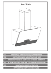
4
PRODUCT IMAGES
Your product should look like the unit below.
3
C2-6104A OPERATION MANUAL
5
UNPACKING AND INSTALLATION
5.1
Shipping Carton
Your unit will arrive double boxed for maximum protection during shipping. You are
encouraged to retain both boxes and all packing material so the unit can be
returned in the unlikely event that repairs should ever become necessary.
5.2
Important Safety Instructions
The AC power cable furnished with the unit should conform to the type in use in
your country. Please compare the plug on your power cable with the power socket
where the unit will be installed.
If you did not receive the correct cable, DO NOT attempt to modify it. Instead,
immediately contact your dealer or contact TV One at the sales office nearest to
your geographic location and request the proper adaptor.
Please also note that the power supply in your unit is active whenever it is plugged
into the power socket – the ‘Standby’ mode of this product still leaves the power
adaptor active.
5.3
Initial Operation Check Using Factory Default Settings
This product can be operated via multiple methods, but for the purposes of initially
acquainting you with the operation of the unit, this manual will address the
operation using the Front Panel controls.
If you have problems using the unit as described below, see the ‘Factory reset’
description shortly afterwards.
5.3.1
Initial operation and test
The simplest way to check that your unit is operating correctly is:
1. Connect one or more DVI-D or analog sources (using a HD15 / DVI-A
adaptor) to inputs DVI-I1 through to DVI-I4
2. Connect a monitor to the DVI-I output connection.
3. Power-up the unit
4. Select the ‘quad-view’ Preset button (left-most button of the built-in presets)
5. Your monitor should now be displaying the input sources you have plugged
in.
Your unit will default to an output resolution of 1280x1024, so make sure your
monitor can accept this.
4
C2-6104A OPERATION MANUAL
6
FRONT PANEL CONTROLS
The range of buttons on the front of the unit provides the user with quick access for
selecting a variety of inputs and features.
The cross-hair (up/down/left/right) buttons on the front panel provides the user with
a way of navigating the Liquid Crystal Display menus (LCD) which is detailed in a
later section.
6.1
Button controls
The following buttons are available on the front of the unit:
Button
Button Function
Menu navigation Up / down / left / right / SELECT allow quick and easy access to
& adjustment
various menu settings. Press and hold SELECT to store current
buttons.
settings into memory. They will then be restored on power-on,
or when a Restore is done. See next section for more
information.
Presets 1 to 5
Recalls a preset. These start off blank, but are available to the
user.
Presets 6 to 10 Recalls a pre-defined present, but can be overridden by the
(shown with
user.
default setups)
A/B/C/D
Selects which of the 4 windows on the screen to adjust.
DVI-U1 to 4
Selects the input for the currently selected window.
KEY
Enables keying for currently selected window – see ‘Adjust
keyers’ menu.
(Key color defaults to black, so black foreground will disappear.)
ZOOM
Jumps to the ‘Zoom’ menu item.
FREEZE
Freezes the currently selected window
CYCLE
Cycles the sources through the 4 windows.
POS
Jumps to the Pan or Pos menu item to allow immediate panning
or positioning of the image.
PIP
Activate picture-in-picture mode for the currently selected
window.
SIZE
Jumps to the ‘Shrink’ menu item to allow the current window to
be re-sized.
STANDBY
Hold in to put the unit into Standby (power-save) mode.
Press once to come out of Standby mode.
5
C2-6104A OPERATION MANUAL
6.2
Menu navigation buttons
The LCD is controlled from the front panel by using these buttons. These functions
let the user navigate through the menu structure or change a parameter, and are
detailed in a later section.
6.3
Advanced menus
System
Advanced menus
[Off]
The above menu item must be ‘On’ to activate certain menu items. These typically
control the more advanced items in the menus.
6.4
Special button combinations and functions
In addition to the ability to perform a factory reset and forcing certain output
resolutions, other button combinations are available:
These button combinations only work when the unit is switched
on and active i.e. with the STANDBY/ON LED is off. They will not
work in Standby mode, or during power-up.
6.4.1
Locking front panel buttons & IR remote control
This can be performed by pressing STANDBY/ON and FREEZE at the same time.
All front panel buttons and IR remote control commands will be disabled, with the
exception of repeating the above combination to un-lock the unit and for storing the
current locked buttons setting (thus letting you make sure the unit always starts up
with the buttons locked). The IR remote’s LOCK and STORE buttons will always be
active, giving another way to turn button/IR remote locking off.
The STANDBY/ON button will flash when the unit’s buttons are locked.
6.4.2
Restore power-on settings
This can be done (without having to turn off the unit) by pressing STANDBY/ON
and the menu navigation SELECT button at the same time until a single beep is
heard.
6.4.3
Factory Reset
If you wish to restore all operational parameters to their original condition (for
example, if saved settings prevent the unit from working with your display monitor),
hold the STANDBY/ON and the SELECT button in together until two beeps are
heard.
6
C2-6104A OPERATION MANUAL
All stored settings except resolutions are lost when the unit is
reset. A Firmware update is the only way to perform a complete
factory reset (including resolution data).
6.4.4
Forcing output to specific resolutions
This can be done by holding down two buttons simultaneously as shown in the
table below:
Buttons
1&A
2&A
3&A
Output resolution
480p (YPbPr)
720p (YPbPr)
1280x1024 60Hz
7
C2-6104A OPERATION MANUAL
7
VIDEO INPUTS AND OUTPUTS
7.1
C2-6104A
This unit has 4x DVI-U inputs, 1x DVI-U background input and 1x DVI-I output.
7.2
Computer & Video inputs
Signal
DVI-U input
Analog RGBHV
RGsB (sync on green)
RGBS (composite sync at TTL levels)
YUV/YPbPr (including tri-level)
DVI-D
HDMI sources
Composite Video (on green)
Analog and HDMI sources will need an adaptor or cable to convert the DVI-I
connector to the relevant connector for your source.
In most cases, the particular input being used will be auto-detected. See ‘Adjust
sources’ for more information on manually selecting an input type.
DVI-U inputs allow a Composite Video source to be used and this will take priority
over a standard definition (525i / 625i) YUV signal. This can be overridden if
required - see ‘Adjust sources’ for more information on manually selecting an input
type.
YUV/YPbPr (component) inputs can also be switched to RGsB (sync on green)
mode if desired – see ‘Adjust sources’ for more information on manually selecting
an input type.
The DVI-D input accepts DVI digital connections (but on a DVI-I socket for added
flexibility). An EDID signal is used to ensure that the PC or DVD player outputting
the DVI signal knows the available range of resolutions in the unit. An EDID
Manager is present that allows the EDID data to be copied from another unit – see
‘Adjust sources’ for more details.
7.3
Computer & Video outputs
The output resolution from your unit is set in the ‘Adjust outputs’ menu using the
‘Output res.’ menu item. The signal format is also selectable in that menu, with the
following available:
8
C2-6104A OPERATION MANUAL
Signal
DVI-I output
Analog RGBHV
RGsB (sync on green)
RGBS (composite sync at TTL levels)
YUV/YPbPr (including tri-level)
DVI-D
This is altered in the ‘Adjust outputs’ menu, where the user can select between the
above outputs. The DVI-D output is always active and follows the color-space of
the analog signal.
YUV/YPbPr (component) outputs can also be switched to RGsB (sync on green)
mode if desired -see ‘Adjust outputs’ in this manual for more information.
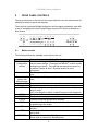
7.4
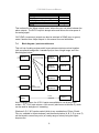
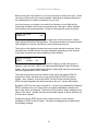
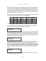
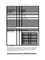
Block diagram / product architecture
This unit has 4 scaling engines and 4 keyers whose outputs are mixed together
(with an optional background / cascade input) to form a single image, as in the
block diagram below:
INPUT 1
Scaler &
Window A
Keyer A
INPUT 2
Scaler &
Window B
Keyer B
INPUT 3
Scaler &
Window C
Keyer C
Scaler &
Window D
Keyer D
Lock
source Z
Keyer Z
INPUT 4
DVI-I
BACK
4x4
Cross-point
Mixer
As the diagram shows, the 4 DVI-I inputs are available for use by any of the
scalers. A 5th DVI-I input acts as a ‘lock source’ (also known as window Z), which
can be used for background / cascading.
Windows A, B, C & D can be scaled (which is any combination of Zoom, Shrink,
Flip, etc. available in Adjust windows), and then each window (A, B, C, D or even Z)
can be keyed to remove any color (or nearby range of colors) using the Adjust
keyers menu.
9
C2-6104A OPERATION MANUAL
The resulting windows are merged together into a single output, according to the
layer priority as set in Adjust windows.
Not shown in the above diagram are the Still Image Stores (SIS1 through to SIS4)
which can provide a static source for the Windows A through D (but not background
Z), nor the border generators which can place borders of any color or opacity
around each window.
5 of the 50 Presets (numbers 6 through 10) built into the unit have been pre-defined
with various sample settings to show some of the available configurations, but can
be overridden by the user.
10
C2-6104A OPERATION MANUAL
8
MENU LAYOUT AND SETTINGS ADJUSTMENT
From here on, we’ll be looking at the menu structure and, more importantly, the
individual menu items that allow you to take advantage of the power of the unit.
You’ll be using the menu navigation buttons and the Liquid Crystal Display (LCD) to
view the options and settings available to you. First press the left / right buttons to
see where you are in the menu. Go into a sub menu by pressing the SELECT
button once. To exit a sub-menu, scroll to the end of the sub-menu by pressing the
right buttons to reveal Exit. Press SELECT to exit the sub menu.
You can also gain fast access to the start and end of a menu by clicking the up or
down buttons.
You can edit a value in brackets ‘[ ]’ by pressing the SELECT button once (you’ll
note that the brackets surrounding a particular parameter’s value will begin to
flash). Change the value by pressing left or right. Then finalize your adjustment by
pressing the SELECT button once more.
A few menu items have multiple parameters within an individual menu selection. In
those cases, you can adjust one item at a time. To do this, move to the next
parameter by moving the multi-directional button left or right.
Adjust windows
H/V zoom pan %
[ 10] 20
Or, you can use the up / down buttons to alter the value following the one in
brackets. Therefore, in the example above, where “[10] 20” is displayed in a menu
item, the one in brackets is adjusted using the left and right buttons, and the second
number be can be altered using the up and down buttons.
Holding the left, right, up or down buttons for a short time will keep adjusting the
relevant value, therefore allowing fast changes to a setting – which is very useful for
positioning something on screen.
Holding the SELECT button in for a few seconds stores all
changes in memory. Unless you intentionally change it again
later, the adjustment will remain even after power is removed
from the unit.
Holding the SELECT button in for a few seconds stores all
changes in memory. Unless you intentionally change it again
later, the adjustment will remain even after power is removed
from the unit. The High Level Menu Structure
Menus are arranged so that a particular general function has a menu name on the
top line and beneath that either a sub-menu or one or more related individual
settings are displayed.
11
C2-6104A OPERATION MANUAL
In some cases the functionality is global – meaning it has an effect on the unit as a
whole (such as changing the output resolution). In the majority of cases, the
function is related to a specific operational area of the unit, detailed by the text in
the top line.
There are two screens that appear before the Group Menus (sub-menus) are
accessed.
CORIO2
TV One
The first is the ‘welcome’ display shown above indicating the model of the unit.
www.tvone.com
SW: 65. PT: 12, BT: 13
Moving to the next menu item displays the firmware information screen (the
numbers on your unit will be different to those shown). The SW number refers to
the version of firmware loaded into the unit, this can be upgraded from the support
website.
The PT and BT numbers refer to Hardware version information and are of interest
to the Technical Support Group should you ever need assistance.
At the end of all Group Menus will be an ‘Exit’ item. Simply select this to exit the
existing menu structure and return to the previous one in the hierarchy.
8.1
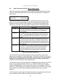
Group Names and Descriptions
Menu Group Name
Group Description
Adjust outputs
Controls output parameters
Adjust windows
Controls characteristics of the pip windows
Adjust keyers
Controls the keying ability of the unit
Adjust borders
Controls window border parameters
Adjust sources
Controls signal source input parameters
Adjust transitions
Controls the method of transition when switching inputs
Adjust tally
Controls optional Tally board functions
Adjust ethernet
Controls IP addresses and network parameters
Adjust resolutions
Controls unit’s input/output resolution table
System
Controls global system parameters for the unit
Note that the ‘Advanced menus’ menu item must be ‘On’ to activate certain menu
items.
12
C2-6104A OPERATION MANUAL
8.2
Items Associated with the Adjust outputs group
This menu group allows adjustments to be made that specifically affect the output
of the unit, including output resolution and locking/overlaying onto a computer or
video source.
800 x 600 60Hz
Lock mode
[Off] [RGB1]
This menu item allows the lock mode to be selected and the lock source to be
defined. The top line of the display shows the current detected resolution of the
selected lock source (RGB1 in this example). The lock mode can be either Off,
Genlock or Lock & Mix, with the operation of these shown in the following table:
Lock mode
Off
Genlock
Lock & Mix
Frm.lock*
Description
The output resolution of the Output is defined by the setting
for Output Resolution and there will be no background
source visible.
The output video will be “Genlocked” to the selected lock
source. The output signal will be synchronous to the input
sync and adjustable but there will still be no lock source
visible.
The output video will be locked to the selected source, the
syncs will be locked (but with an additional internal video
processing delay) and the background for the output will be
that of the Lock source (unless foreground and background
are swapped).
The frame rate of the output will be locked to the frame rate
of the input. This can only work if the output resolution
frame rate matches that of the lock source frame rate.
‘Frm.lock’ will flash until a highly stable lock has been
achieved.
*Only certain models support this.
In both Genlock and Lock & Mix modes the source selected for the lock input
determines the resolution of the Output image. The output resolution for the entire
image can be no different than the resolution of the lock source. All synchronization
signals are re-generated within the unit so they may look slightly different when
compared on an oscilloscope to the original source.
In Frame-lock mode, the output resolution is independent of the lock source, but the
frame-rate must match that of the source (e.g. 1280x1024 60Hz can be framelocked to 640x480 60Hz). Frame-lock is very useful for synchronizing a HD-SDI
output (e.g. 1080i 59.94Hz) to a composite video source (e.g. NTSC), or for scaling
one resolution to another while avoiding any potential frame-rate conversion
artifacts.
'H/V shift' can be used to align the output to the input more accurately, but this may
cause instability until the lock is re-acquired ('Frm.lock' will flash).
13
C2-6104A OPERATION MANUAL
Before turning the Lock feature on, you first must select a valid Lock source. Some
units may not have all Lock sources available, depending on hardware limitations –
see Specifications for details of limitations on your unit.
If the Lock source you choose is not valid, then Genlock or Lock & Mix will be
temporarily disabled, until the Lock source becomes valid again. When disabled,
the resolution previously specified in ‘Output res’ becomes the output resolution.
1024 x 768 60Hz
Output res.
[28]
Your unit can handle a very wide array of inputs and convert them all to a single
output signal with defined characteristics. This output resolution will remain in place
until changed or it may be overridden by the lock mode and source.
The top line of the display will show the current output resolution selected. Some
units will have a limited number of output resolutions depending on their function
(e.g. Down Converters are more limited than Video Scalers).
1024 x 768 60Hz
HDCP
(Active)
On
HDCP is handled only on certain units with DVI outputs, so this menu may not
appear on your own unit. HDCP is a ‘High-bandwidth Digital Content Protection’
system, which can ensure that a high definition video signal cannot be received by
units not equipped with a HDCP receiver.
This menu lets you see the current status of the output and whether HDCP is
supported or active, and also lets you turn off the output’s HDCP encryption
system. Note, however, that turning HDCP off at the output will also prevent
HDCP-encrypted signals from being received by the unit – see the table below.
By default, HDCP on the output is turned On - so that if your attached DVI display is
HDCP-compliant, then your output will be encrypted (regardless of whether the
input to the scaler is encrypted). Note that you don’t have to attach a display to the
output of the scaler – another unit can be connected instead, in which case that unit
is known as a ‘repeater’.
Please also see the HDCP menu item in ‘Adjust sources’, as this controls
availability of HDCP at the DVI input. The status message given in brackets has
the following meaning:
14
C2-6104A OPERATION MANUAL
Status
message
No display
Unavailable
Supported
Active
Rep. supprt
Rep. active
Description
Effect
There is no display attached
(HOTPLUG is low).
The device attached is not
capable of support ing HDCP.
Nothing will be output on the DVI connector.
The device attached is
capable of HDCP, but the
output is not currently
encrypted.
The device attached is
capable of HDCP, and the
output from the unit is
encrypted.
The repeater unit (e.g. scaler)
attached is capable of HDCP,
but the output is not currently
encrypted.
The repeater unit (e.g. scaler)
attached is capable of HDCP,
and the output from the unit is
encrypted.
Adjust outputs
Output type
As the DVI output cannot be HDCP encrypted, then
a HDCP-encrypted source cannot be selected for
scaling.
As the DVI output is not HDCP encrypted, then a
HDCP-encrypted source cannot be selected for
scaling.
As the DVI output is HDCP encrypted, then a
HDCP-encrypted source can be selected for
scaling. Note that no other output connector (SDI,
CV, YC, YUV or RGBHV) will function – since they
are not encrypted.
[RGBHV]
Adjust outputs
Anlog= [RGBHV] Dig= RGBHV
This menu may appear as either of the above – depending on whether the analog
and digital outputs are controlled separately.
This menu item allows you to select the type of signal output your unit will provide.
Types of output vary depending on the resolution selected and include various
types of component signals YUV or tlYUV (tri-level YUV) and the full range of RGB
type signals RGBHV, RGBS and RGsB (Sync on green).
Note that this value is remembered for each resolution – so you can set 1024x768
60Hz to RGBHV and 1280x720 60Hz to tlYUV and both will be remembered
separately. This value is not affected by a Factory reset – but is reset by a firmware
update.
Adjust outputs
Optimize for SDI
[On]
This menu item is only available on certain units with an SDI output and when
locking to a CV or YC input. An internal de-jitter circuit ensures that the SDI output
has a low jitter over the full 10Hz to 100kHz range, even though the CV or YC input
may have a high jitter. However, this is not always compatible with a CV/YC output
where the colour sub-carrier should not be de-jittered and needs to follow a Lock
15
C2-6104A OPERATION MANUAL
source’s input – hence it should be turned Off it the CV/YC outputs are going to be
used.
Adjust outputs
Stand. [NTSC-M/PAL-BDGHI]
This menu item is only available when the Output resolution is set to PAL or NTSC.
With this you can change the output type to the PAL or NTSC standard with the
further option of changing the output to the additional PAL & NSTC standards such
as PAL-M or PAL-N. SECAM is also available as an output on some units,
provided the ‘Output res’ is set to PAL / 50Hz.
Adjust outputs
Luma/chr BW
[Med] / [Med]
This menu item is only available on certain units when the Output resolution is set
to PAL or NTSC. With this you can change the output filtering system to increase or
decrease the image sharpness. In general, high sharpness can result in increased
colour disturbance.
Adjust outputs
Back Y/U/V
[ 16] [128] [128]
Sets the value of the fixed background color, which is present when PIP is used
with no Lock source background displayed. This menu item is only available for
units with overlay, keying and fading abilities.
Adjust outputs
Audio emb.
[On] [DVI-U1]
For certain units with HDMI and/or SDI-compatible inputs and outputs, the audio
can be de-embedded from the video signal and sent to a compatible output.
‘On’ enables this to happen, and allows the audio source to be selected. ‘WinA’
sets the audio source to follow that of the main window’s video source.
8.3
Items Associated with the Adjust windows group
This menu group allows adjustment to be made to window specific parameters such
as the window source, its position, size and zoom level.
Window size adjustment can be performed in a number of different ways according
to whether ‘Aspect adjust’ is set to Simple, Advanced or Pixel. The main part of this
text assumes Simple mode – see later for a detailed description of the other modes.
Adjust windows
Window to adjust
[A]
16
C2-6104A OPERATION MANUAL
This menu item only appears on units with multiple windows or PIPs. It is used to
select which one you want to modify. Alternatively, use one of the dedicated
buttons on the front panel to choose the window to adjust.
NTSC / 60Hz
Source
[ YC1]
The source display screen allows the input source for the currently selected window
to be changed. The top line of the display shows the detected characteristics of the
signal. Valid Input sources match those available on the front of the unit.
Certain units do not have full flexibility of Window source and Lock source when
Genlock or Lock & Mix are active (in the Adjust outputs menu group). See the
Specifications for your unit to see if any limitations are present.
Adjust windows
Window enable
[ On]
Available on certain units only, this quickly enables or disables the window being
adjusted.
Adjust windows
Zoom level %
[ 100]
Changing this option, sets the amount of picture magnification you wish to use for
the window Source. You are provided with the options to zoom the image from
100% to 1000% (10x zoom).
Adjust windows
H/V zoom pan %
[ 50] [ 50]
Once an image has been ‘zoomed’, this control allows the image to be positioned
within the window so that any portion can be seen, not just the middle.
Adjust windows
Image freeze
[Off]
This menu item allows the image to be frozen or unfrozen – thus keeping a single
image on screen indefinitely. Note that images are not stored when power is
removed from the unit.
Adjust windows
H/V crop % [ 0]
0
This allows the scaled image to be cropped at the top/bottom edges, or at the sides.
Typically, this is used when performing a picture-in-picture (PIP) function (only
available on certain models), where the incoming video signal has a letterbox or
pillarbox size (i.e. it has black areas at the top/bottom or sides).
17
C2-6104A OPERATION MANUAL
By adjusting the H/V values, you can crop out the black areas to correct the size on
the final output screen. Note that it does not change the shape or aspect ratio of
the image – but just removes the parts of the image that are not required.
Adjust windows
H/V out shift
[ 0] [ 0]
This positions the selected Window horizontally and vertically on the monitor. This
should only be used for ‘fine tuning’ and should not normally require adjustment –
use the Shrink H/V adjustment when your image is less than 100% Shrink value.
Adjust windows
Shrink level%
[ 50] [On]
Shrink Level determines the percentage of the monitor’s total available screen
space that the selected Window image occupies. Adjustment is provided for a
reduction down to 10% of the overall output size. In most cases, this feature is
used for picture-in-picture (PIP) when a background image is being used (for units
with overlay abilities).
Note that some units do not have the [On] entry – this is only for units with a PIP
button on the front, with turns this entry On and Off. On these units, this feature is
‘Off’ by default, so that the full image size of 100% is used. Shrink level will need to
be turned On before any change to this value has an effect.
Adjust windows
H/V position %
[100] [ 50]
This menu option determines the position of the shrunken image on the monitor
screen. This will move an image that is less than the full screen size left/right or
up/down within the monitor’s available screen space. It will not let you move the
image off the screen, so certain values will appear to have no effect (unless you
use a very low Shrink value like 10%).
Adjust windows
Aspect change
[Normal]
This item provides a simple way of changing the output screen aspect ratio, to suit
the incoming video signal and final output display size. Use the zoom/shrink
functions for occasions when the aspect ratio is an odd format.
Adjust windows
Aspect adjust
[Simple]
See later section for further details on this item.
Adjust windows
Temporal interp.
[Off]
18
C2-6104A OPERATION MANUAL
This is a feature only present in advanced units only. It greatly improves the
method of frame-rate conversion, by allowing the unit to merge frames together
during the process.
When ‘Off’, the unit will use frame-repetition when converting 50Hz to 60Hz (i.e. it
has to duplicate every 5th frame), or frame-dropping when converting 60Hz to 50Hz
(i.e. it has to drop every 6th frame). When ‘On’, smooth blending is applied so that
frames are not lost, but blended together at the appropriate times.
Adjust windows
Flicker Reduction
[Low]
The Flicker Reduction menu item will only appear if you have selected a low
resolution interlaced output such as PAL or NTSC. If you are using CV or YC
outputs, this adjustment may be of interest, particularly when you have line
drawings or similar fine detail. You can choose from four possible Flicker Reduction
settings. You should use as little Flicker Reduction as possible because the Vertical
detail will be softened at the highest setting.
Flicker mode
Off
Low
Med.
High
Adjust windows
Image smoothing
Function
Disables flicker reduction (sharpest mode).
Suitable for most input sources.
Enough for most situations such as thin line drawings
Highest amount of flicker reduction. Will cause loss of
vertical detail in some images.
[Auto]
Image smoothing reduces the jagged-edges sometimes seen within an output
image by softening it. It typically improves the quality of a scaled image greatly.
There are four possible settings for this adjustment: “Off”, “Med.”, “High”, and
“Auto”. The “Auto” setting is generally thought to be most desirable and will vary the
smoothing process according to the amount of zoom taking place.
Adjust windows
Image flip
[Off]
Occasionally, it’s necessary to cause the output image to be flipped Vertically,
Horizontally or both – most commonly when a video projector is ceiling-mounted, or
for special effects.
Adjust windows
Show source label
[On]
Units that support source labeling have this menu item available, which allows the
label to be turned on or off on a window-by-window basis.
19
C2-6104A OPERATION MANUAL
Adjust windows
Audio bars
[4]
Certain units can display audio bar measurements and this menu item displays how
many stereo-bars are shown. A maximum of 4 stereo bars (8 bars in total, with leftright pairs next to each other) can be shown. Audio channels are always numbered
from left to right, balanced to display bars on both sides of the each. A setting of 0
disables the audio bars from being shown.
Adjust windows
Max fade level %
[100]
This Menu item fades the selected layer, and is only available on models with
overlay abilities. Adjustment range is from solid to fully transparent.
Note: This menu item only appears on multi-channel scalers:
Adjust Windows
Layer priority abABZ
[ 3]
This adjustment selects the order of the window layers. Layers are shown for ‘a’
and ‘b’ logo screens, Window ‘A’, Window ‘B’ and ‘Z’ is the Lock Source. The
default condition is shown. The number shown is the current layer of the active
window, when you adjust the layer number the layer stack indicator ‘abABZ’ will
change to allow visualization of the layer stack. Note that layer 6 the Background
Color is not shown as its layer position can not be altered – it will always be the
background.
8.3.1
Extended scaling controls
The ‘Aspect adjust’ parameter is used to change the way that scaling of windows is
controlled. By default it is set to ‘Simple’ which allows basic control of the window
zoom and shrink sizes and positions – enough for simple tasks.
In ‘Advanced’ mode, it allows the horizontal (H) and vertical (V) components of the
Zoom and Shrink functions to be adjusted independently, thus allowing custom
aspect ratios to be created, or to convert from one aspect ratio to another.
In ‘Pixel’ mode, the user has direct access to pixel and line-accurate scaling
functions. This lets the user specify the exact co-ordinates and size of the source
image (within the video source), and the position and size of where this is placed in
the output video signal.
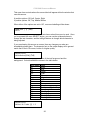
The table below summarizes the different menu items in the different modes – the
‘Simple’ items have already been described earlier in this section, so only the
‘Advanced’ and ‘Pixel’ ones that are different (highlighted in bold) will be detailed
here.
20
C2-6104A OPERATION MANUAL
Simple
Zoom level % [100]
H/V zoom pan% [50] 50
H/V crop % [ 0] 0
Shrink level % [50] Off
H/V position % [50] 50
8.3.2
Advanced
Pixel
Zoom H/V [100]100 1.333:1 In [ 0],0 640,480
H/V zoom pan% [50] 50
Out [ 0],0 640,480
H/V crop % [ 0] 0
ShrnkH/V [50] 50 1.333:1
H/V position % [50] 50
‘Aspect adjust’ = ‘Advanced’
Adjust windows
H/V zoom % [100] [100]1.333:1
This item allows the independent setting of the horizontal and vertical zoom values.
The third number (1.333 in the example) is the Aspect Ratio resulting from the
adjustments, which is automatically calculated for you based on the incoming
resolution and the H & V Zoom values.
Most resolutions are 4:3 ratio, thus the third number will be 1.333 (4 divided by 3).
Another common aspect ratio is 16:9 (16 divided by 9 = 1.777). PAL and NTSC
inputs are physically 4:3 on your video monitor, but their actual pixel/line ratios are
different and so will not display as 1.333.
Adjust windows
Shrink H/V % [100] [100] 1.333
This item allows the setting of different Horizontal and Vertical ‘shrink’ sizes. The
third number (1.333 in the example) is the Aspect Ratio resulting from the
adjustments, which is automatically calculated for you based on the output
resolution (the actual pixels & lines, not your physical screen size) and the H & V
Shrink values.
Most resolutions are 4:3 ratio, thus the third number will be 1.333 (4 divided by 3).
Another common aspect ratio is 16:9 (16 divided by 9 = 1.777). Therefore, to
convert your 4:3 output into a 16:9 output, reduce the vertical (V) Shrink value to
75% and this will simulate a 16:9 output. PAL and NTSC inputs are physically 4:3
on your video monitor, but their actual pixel/line ratios are different and so will not
display as 1.333.
8.3.3
‘Aspect adjust’ = ‘Pixel’
Adjust windows
In
[ 300] , 150
750, 400
Adjust windows
Out
[ 50] , 50
250, 300
These menu items work together to specify the exact co-ordinates and size of the
source image (within the video source) and the position and size of where this is
21
C2-6104A OPERATION MANUAL
placed in the output video signal – in other words the ‘In’ and ‘Out’ positions and
sizes.
The diagram below should help to clarify the function of these values:
0
1024
0
1024
0
0
OUT
IN
768
768
In the example above, ‘In’ has been set to 300,150 as its top-left source coordinate, with a size of 750,400. ‘Out’ has been set to 50,50 (i.e. close to the top
left) with a size of 250,300.
The scaler will then ensure that the whole of the source (of size 750 by 400) is
scaled to the required output (of size 250 x 300).
8.4
Items Associated with the Adjust keyers group
Please note that not all units have this sub-menu – it is only present on units with
overlaying abilities.
Towards the end of this manual you will find a section titled ‘COMMON
OPERATIONS’ – this gives a step-by-step guide to keying out a particular color.
Adjust keyers
Keyer enable
[Off]
This menu item turns keying On or Off for the current foreground. A keyed image is
in essence one image superimposed over another – such that portions of the top
image are made transparent (keyed out), so that the background image can show
through. The following settings allow you to vary the colour(s) that are keyed out.
Adjust keyers
Swap fore/backgrnd
[Off]
This menu item is only present on single-channel scalers – dual and quad-channel
scalers have the layer priority set within the ‘Adjust Windows’ menu.
This menu item allows you to swap the foreground and background images when
Lock mode is set to Lock & Mix. It will have no effect in any other mode (since no
background is present).
22
C2-6104A OPERATION MANUAL
Normally, your foreground is the input (window) source and your background is the
lock source. This then allows you to superimpose any graphics or video input on
top of the lock source by keying out a certain color or range of colors in the input
source. Swapping them means that the input source moves to the background and
the lock source is now in front of it. Thus you are now keying out the lock source
colors to reveal the input source behind it.
Note that this is different to simply swapping over the input and lock sources as that
would affect the final output resolution – see examples below:
Input
Lock
source source
XGA
NTSC
XGA
NTSC
NTSC
XGA
NTSC
XGA
(XGA is 1024x768)
Swap
Off
On
Off
On
Foreground
(keyed)
XGA
NTSC
NTSC
XGA
Background
(non-keyed)
NTSC
XGA
XGA
NTSC
Output
resolution
NTSC
NTSC
XGA
XGA
You will see that the Swap between foreground and background has no effect on
the output resolution as this is always set by the Lock source.
Adjust keyers
Y Key min/max
[ 0] [ 32]
The Min/Max parameters are used to select what range of Y (luminance/grey-scale)
values are made transparent within the selected window/lock source. In order to
key out part of an image, start with the max value and increase it until the required
lighter parts within the window/lock source disappear. Then adjust the min level to
bring back any darker parts of the image.
Adjust keyers
Y Key softness
[ 0]
The Y Key softness option removes noise from the keyed image, generally at the
edges. Adjust as required to make the edges of the key as sharp or as soft as
desired. The noise is where the analog to digital process (A/D conversion) may not
sample a 50% brightness as being exactly 50% i.e. sometimes 49% and sometimes
51%. Increasing the softness value will broaden the range of keyed colors so that
the keying of images varies depending on how close a color is to the keyed-out
range.
Adjust keyers
Y Key invert
[Off]
The Y Key invert changes the keying characteristics with respect to what colors of
the foreground image you wish to ‘key out’.
23
C2-6104A OPERATION MANUAL
Setting it to Off will cause the colour range that’s defined to be removed - remove
the desired colors. Setting it to On will cause the colour range that’s defined to be
kept - key out all other colors.
The descriptions above behave identically on the remaining U Key Invert & V Key
Invert component versions. However they are directed at the U/B-Y (blue) colour
component and V/R-Y (red) colour components respectively. Adjustment and
effects are the same as explained above for Y Key Invert (brightness/grey-scale).
8.5
Items Associated with the Adjust borders group
The adjust borders menu allows the border function of your unit to be enabled –
with one border being available for each Window, Logo and Lock source.
Note that the layer priority of the Border is the same as the Window source that it is
‘attached’ to.
Adjust borders
Border to adjust
[A]
Select the window / logo / lock source you wish to adjust.
Adjust borders
Border enable
[On]
Allows a border to be turned off and not displayed on the output screen.
Adjust borders
Brdr size H/V
[8]
x
[8]
This adjustment allows the height and width of the border to be changed it can
be up to 255 pixels thick.
Adjust borders
Brdr offset H/V
[0]
x
[0]
This allows the border to be offset from the window. A typical application is the
creation of a drop shadow effect. For example this can be achieved by setting the
border size to 0 and then adjusting the H and V offset to 10 pixels.
Adjust borders
Brdr Y/U/V
[16] [128] [128]
The color of the border can be changed to any color by adjusting the Y, U and V
parameters. Y is the luminance, with U and V altering the blue and red content
respectively. E.g. increase both U and V to give a purple colour, or decrease both
to give a green colour.
24
C2-6104A OPERATION MANUAL
Adjust borders
Brdr opacity %
[100]
This parameter controls how visible the border is to the viewer. A setting of 0
renders the border invisible (transparent) whereas a setting of 100 makes the Logo
fully visible. (In-between settings can give the Border a transparent appearance.)
8.6
Items Associated with the Adjust sources group relating to source
labeling
The ‘Adjust Sources’ menu group accesses the parameters associated with each
input present on your unit. Parameters relating to the video signal are detailed in a
later section – this section solely relates to the source labelling function.
It is recommended that you Store your settings once you’re happy with them in
readiness for future use.
Source: DVI-I1
Source to adj
[DVI-I1]
This menu item selects the input connection for which you want to make
adjustments to. As in the image above, changes will only be made to the source
connected to DVI-I1. Once the selection has been made, all changes made using
the following operating parameters will only apply to the selected input.
8.6.1
Tally / UMD module support
If a Tally / UMD module is installed, then an extra menu item will appear:
Source: DVI-I1
UMD display address
[0]
This menu item allows each video source to receive a UMD (under-monitor display)
text string and use that as the source’s label.
To do so, each source must have its own identifying display address number – and
the UMD data source must use the same number when sending the data packet.
When a UMD packet is received that has this display address, the text received in
that packet overwrites the existing source label.
See ‘Adjust tally’ for wiring connections on the Tally / UMD module.
8.6.2
Source labeling
Source: DVI-I1
Lbl HVpos [Center] [Bottom]
25
C2-6104A OPERATION MANUAL
This menu item controls where the source label will appear within the window that
uses this source.
H position options: Off, Left, Center, Right
V position options: Off, Top, Middle, Bottom
When either of the options are set to ‘Off’, no source labelling will be shown.
Label char [ 1] ( 068)
DVI-I1
In this menu item, you can change the text shown when this source is used. Once
you’ve pressed the menu SELECT button, you can use the up/down buttons to
change the text character, and the left/right buttons to change which character is
being adjusted.
If you are showing this source on-screen, then any changes you make are
immediately shown there. The character font on the output display will in general
match that of the LCD screen, but be of a higher quality.
Source: DVI-I1
Lbl for/bck col [Wht] [TrB]
This menu item lets you change the color of the text foreground and the
background. Colors available are shown in the table below:
Menu name
Blk
Blu
Grn
Cyn
Red
Mag
Yel
Wht
Trn
Gry
TrB
TrW
FlB
FlG
FlR
FlW
Color
Black
Blue
Green
Cyan
Red
Magenta
Yellow
White
Transparent
Grey
Transparent Black / Grey
Transparent White
Flashing Blue
Flashing Green
Flashing Red
Flashing White
Source: DVI-I1
Lbl font / H / V size [1] 1 2
26
C2-6104A OPERATION MANUAL
This menu item allows the font, H-Size and V-Size of the characters to be altered.
If you make the font size too big, it may become corrupted or disappear.
8.7
Items Associated with the Adjust sources group
The ‘Adjust Sources’ menu group accesses the parameters associated with the
processing amplifiers used for each input (RGB, CV, YC, etc.). They allow you to
fine-tune an incoming signal to optimize its color, brightness or even sharpness.
Not all settings are available for all input types, and not all input types listed here
may be available on your unit. Also note that many of these adjustments may not
show without ‘Advanced menus’ set to On.
It is recommended that you Store your settings once you’re happy with them in
readiness for future use.
Source: RGB1
Source to adj
[RGB1]
This menu item selects the input connection for which you want to make
adjustments to. As in the image above, changes will only be made to the source
connected to RGB1. Once the selection has been made, all changes made using
the following operating parameters will only apply to the selected input.
Selection of a CV/YC source will reveal different menu items that allow adjustments
beyond those used for RGB sources. The menu discussions that follow relate first
to RGB sources, then to CV / YC type sources.
8.7.1
Menu items common to all inputs
Source: RGB1
Aspect correct
[ Fill]
This menu item will be used to correct the aspect ratio of the video source when
converted into the final output resolution. The following table details what happens
in the available modes:
27
C2-6104A OPERATION MANUAL
Setting
Fill
(default)
Aspect
H-fit
V-fit
1:1
Result
The source is stretched to fill the output.
The source’s aspect ratio is maintained on the output.
The source is stretched to fill the horizontal dimension of the output, with
the vertical dimension stretched by the same amount (and possibly
clipped).
The source is stretched to fill the vertical dimension of the output, with
the horizontal dimension stretched by the same amount (and possibly
clipped).
Each source pixel is represented by a single output pixel – no scaling
will be performed. If the input resolution is higher than the output, then
only part of the source will be seen. If the input resolution is lower than
the output, then a black border will be present.
Source: RGB1
TL pos. adj.
[ 0] [ 0]
This menu item allows manual positioning of the Top and Left portion of the image.
It is used to ensure that the input signal is captured correctly, eliminating any black
borders. These settings are often used to correct the position of a PC signal on an
input, or to eliminate any undesired noise at the top or bottom of a PAL or NTSC
video source.
Source: RGB1
BR size adj.
[
0] [ 0]
This menu item allows manual positioning of the Bottom and Right portion of the
image. These settings are often used to correct the position of a PC signal on an
input, or to eliminate any undesired noise at the top or bottom of a PAL or NTSC
video source.
Source: RGB1
Audio input source
[ 1]
If your unit has an internal audio switcher / selector, this menu item selects the
desired Audio input for use with the active video source, allowing an audio-followvideo function.
Source: RGB1
OPTION audio source
[ 1]
If an external audio switcher is connected via the OPTION bus, then this menu item
selects the desired Audio input for use with the active video source, allowing an
audio-follow-video function.
28
C2-6104A OPERATION MANUAL
In most situations, the Audio input values would be different for each video source –
so that when the first video source is selected, so is the first audio source (this is
called ‘audio follow video’). The second video source then selects the second
audio source, etc. However, there is nothing to prevent all Audio input values being
set to the same value, for ‘audio breakaway’.
Source: RGB1
Audio
Vol [ 1] Bal [ 0]
This menu item adjusts the audio volume and balance for the selected audio
channel. This is only functional for certain units when an optional Audio Switcher is
attached.
Source: RGB1
On source loss
[Blue]
(This has replaced ‘De-glitch’ used on previous firmware versions.)
This option is used to tell the unit what to do if the video source is lost or becomes
unstable. Options are:
Option
Show
Freeze
Blue (default)
Black
Remove
Description
Shows all picture break-up and instabilities.
Freezes the latest frame – un-freezes as soon as the
source becomes stable again.
Turns the window blue, to represent source loss.
Turns the window black.
Removes the window, thus showing any background
(e.g. a Lock source). This is useful for MIX & PIP
scenarios on units with overlay abilities.
If you have a very unstable input, such as a video tape player with a poor (jumping)
output signal, you may wish to turn the setting to ‘Show’.
Source : RGB1
De-int
[M.comp med]
An interlaced input consists of two fields separated in time. Both fields are required
in order to make up the full resolution input image, but since they are sent one after
the other, a moving image will have “motion artifacts” if the two fields are simply
combined together. The most common artifact is a blurring at the point of maximum
movement within an image. Your unit provides some tools to minimize the effects of
de-interlacing of an image.
The following options are available for this menu item:
29
C2-6104A OPERATION MANUAL
Mode
Normal/weave
Auto
Film 3:2
M. Comp Low
M. Comp Med.
M. Comp High
Frame/bob
Function
The two interlaced fields are simply combined/weaved
together. This will often show artifacts on moving images,
but can be used when the input is known to be still.
Automatically selects Film 3:2 or Medium Range Motion
Compensation (M. Comp Med.) depending on whether Film
Mode is detected or not.
Enables 3:2 pull down conversion of the incoming NTSC
video. (This option should not be used if the source is not
NTSC video).
Enables Pixel Adaptive Motion Compensation. Three levels
are available with ‘Low’ providing the least compensation
for Motion and ‘High’ providing the most compensation.
The two fields are shown consecutively.
Source : RGB1
Diagonal interp.
[Off]
This menu item allows the user to specify whether the source has diagonal
interpolation applied to it when de-interlacing occurs. This reduces ‘jagged’ artifacts
on moving images, however is not suitable for noisy sources where the noise could
be mis-interpreted as a diagonal or sloping element of the picture.
Source : RGB1
Noise reduction
[Off]
This menu item allows the user to specify whether the source has noise reduction
applied to it. This is performed by averaging the video signal over a number of
fields – but ignoring areas where motion has occurred. If motion blurring is seen, it
is recommended to turn this setting off.
8.7.2
DVI Source Menu Items
Source: DVI1
HDCP
[Inactive]
[Off]
HDCP is supported on certain units only - and only on the DVI input connector.
This menu item lets you change whether HDCP is active on this particular DVI
input.
If turned ‘Off’, then a source that requires HDCP encryption will not send a video
signal to your unit.
If turned ‘On’, and a HDCP-compliant display or device is attached to your unit’s
DVI output, then HDCP encrypted sources can be used.
The following table summarizes the message given in brackets:
30
C2-6104A OPERATION MANUAL
Status
message
Inactive
Active
Description
Effect
HDCP is not active
at the DVI
connector.
HDCP is active at
the DVI connector.
HDCP-encrypted material cannot be received
by the unit.
HDCP-encrypted material can be received by
the unit, but only if a HDCP-compliant display
or device is attached to the unit’s output.
See ‘Adjust outputs’ for a description of how the HDCP system works on your
scaler.
Source: DVI1
Display emul. EDID
[DVI]
This feature is only present on certain units – it is used with the next menu item to
form a simple ‘EDID Manager’.
EDID is an information packet retrieved by a PC graphic card over a DVI link from a
monitor which tells the graphic card which resolutions the display supports. In the
case of your unit, it tells the graphic card what resolutions are compatible with it –
by emulating a display.
The above menu lets the user select which of 8 EDID data blocks are ‘shown’ to a
PC or other DVI/HDMI source. (It does not affect any other input.) Note that some
graphic cards will usually only read the EDID data when the cable is first connected,
or on power-up.
The 8 EDID blocks are as follows:
EDID Usage
Mem1
Mem2
Mem3 User-definable – see ‘EDID capture’
Mem4
Mem5
Mem6*
HDMI* Default HDMI EDID data for your unit
DVI
Default DVI EDID data for your unit
Mon
The attached monitor’s EDID data
*Your unit will have either Mem6 or HDMI, but not both.
If you change this value, you’ll need to store your settings and then re-boot the
CORIO2 unit at least once to ensure that the source sees that the EDID data has
changed.
31
C2-6104A OPERATION MANUAL
It should also be noted that some graphic cards will require your PC to be re-booted
before they see that a change has occurred.
If your unit allows ‘HDMI’ to be selected, this can also enable certain audio features
depending on the abilities of your unit.
Source: DVI1
EDID capture
[ 1]
Grab
This menu provides a simple way of capturing EDID data from an attached DVI or
HDMI monitor and storing it in one of the user-definable EDID memory data blocks
(Mem1 to Mem6) – see previous menu.
To capture a different display's EDID, perform the following:
1. Connect that display to the DVI output of the CORIO2 unit - the CORIO2 unit
will then read it automatically and store it in the ‘Mon’ EDID entry.
2. Select which EDID memory (Mem1 to Mem6) to copy this information to.
3. Select 'Grab' and click on it - this will copy the current monitor's information
to that EDID memory.
4. Change 'EDID to use' to that memory location (Mem1 to Mem6).
5. Store your unit’s settings (see earlier in this manual on how to do this).
6. Re-boot (turn off and on again) the CORIO2 unit to ensure that the graphic
card uses this new EDID data (you may need to re-boot your computer as
well).
Using the above, up to 6 custom EDID settings can be stored in the CORIO2 unit,
ready for recall later. This is useful to simulate another display being attached to a
graphic card.
8.7.3
RGB Source Menu Items
Source: RGB1
Autoset status
[Inactive]
Once the Autoset sense setting has been made, this menu item is accessed and
activated. The Autoset sense utility will then correct the pixel phase and then
position the Top Left portion of the image and the Bottom Right portion of the
image. Once complete it then resume inactive status.
Source: RGB1
Input pixel phase
[ 16]
Since an image pixel is a very small element of the total image, it’s possible for your
unit’s Analog to Digital converters to wrongly sample the picture on the edge of
each pixel thereby losing image resolution and creating image noise. The Input
32
C2-6104A OPERATION MANUAL
pixel phase adjustment allows you to change the position (from 0 to 31) where the
pixels are sampled, relative to the horizontal sync signal.
To make this adjustment, select an RGB source and then provide an image from
that source with fine detail, preferably with very sharp vertical lines. Adjust this
value until you see the sharpest image. Alternately, adjust this value to give the
worst (noisiest/softest) image, and then add or subtract 16 to get the optimum
value.
Note that the AUTOSET function (for RGB inputs only) will attempt to automatically
work out the best value for this setting.
Source: RGB1
RGB input type
[RGBHV]
There are several types of signals that are called RGB signals as a generic term.
Each has slightly different characteristics that set it apart from similar RGB signals –
such as how the synchronization signal is sent. This menu item lets you set the
input type to use.
Available options let you select whether the input is standard RGB or YUV
(including YPbPr signals with a tri-level sync). For some units, it also allows
selection of break-out BNC connectors to be used instead of the normal connector
(signified by B- in front of the signal type).
Source: RGB1
RGB contr.
[100] [100] [100]
This menu item lets you adjust the individual RGB or YUV/YPbPr signals, in case
one component is at a different contrast to other, or if they all need to be boosted or
lowered.
8.7.4
CV & YC Source Menu Items
Of the above Source Menu items, the Autoset sense and Autoset status functions,
RGB type and Pixel phase are specific to RGB signals only. The rest of the Source
menu items function with RGB, CV or YC type signals. In addition, there are four
additional Menu items that are only used with CV or YC type signals and these are
explained below:
Source: YC1
Bright [100]
Contrast [100]
Adjust the Brightness and Contrast of the image to your requirement.
Source: YC1
Satur [100]
Hue [0]
33
C2-6104A OPERATION MANUAL
Saturation is the amount of color present in the image. Hue is the color “tint”
parameter and the adjustment range is +90 degrees through to -90 degrees with 0
being the default.
Source: YC1
Sharpness
[0]
Within limits, you can enhance or soften the appearance of detail within an image.
The Sharpness values go both negative and positive, with 0 being the default. Note
that over-enhancing an image has the side effect of making it appear to be noisy
and under-enhancing an image gives the appearance of poor video quality.
Source: YC1
Luma delay
[ 0]
On occasion, a video source will have the color portion of the signal offset from the
luminance portion. If you’ve ever seen a poor quality comic book that has the
outline of the cartoon character’s head in one place on the page but the flesh tones
for the head offset slightly, you are seeing the print equivalent of Luminance to
Chrominance Phase Delay.
Fortunately, your unit provides a way for you to make the two signals occur at the
same time on the selected image. The adjustment range provides both positive and
negative levels of delay with 0 being the default.
8.7.5 Still Image Store / Testcard Source Menu Items
Source : TC1
Testcard
[ 0]
This item is only available for units supporting Still Image Stores (SIS) or Testcards
(TC) – which are the same thing, but may be named differently depending on your
unit.
Used to select the image from memory to use as a source for the SIS / TC source
currently selected. Dedicated software can be used to upload user-defined images
– see our website.
8.8
Items associated with the Adjust transitions group
Please note that not all units have this sub-menu – it is only available on some units
with overlay and keying abilities.
Transitions control how your unit responds when a source is changed. Fades
between sources, as well as wipes and cuts, are possible. The amount of time
taken by a transition is controllable from instant transition (a ‘cut’) to several
minutes.
34
C2-6104A OPERATION MANUAL
Adjust transitions
Transition
[Fade]
This first adjustment controls the type of transition desired: ‘Cut’, ‘Fade’, ‘Wipe’ or
‘Push’.
If you select ‘Cut’ or ‘Fade’, the only remaining menu items will be ‘Switching Fade
Time’ and ‘Exit’. Selecting ‘Wipe’ or ‘Push’ exposes additional parameters.
Adjust transitions
Switching fade time
[ .5]
This parameter controls how long a transition from one input to another takes. The
value can be 0 (a cut) or several minutes - adjustable in 1/10th second increments.
Adjust transitions
Wipe type
[Left -> Right]
If you selected ‘Wipe’ or ‘Push’ for the transition type, then you will be able to
specify the ‘movement direction’ of the transition that you want. Both ‘Wipe’ and
‘Push’ support: Left to Right, Right to Left, Up/Down (Top to Bottom), Down/Up
(Bottom to Top). ‘Wipe’ also supports: Diagonal and Diamond effect.
Adjust transitions
Wipe size
[100]
Wipe Size sets the ‘granularity’ of the ‘Wipe’ effect and so is only shown when
‘Wipe’ is the transition type. The smaller the number, the more elements there are
to the wipe. To clarify by example, if you select the Diamond wipe effect and set a
small number into the Wipe Size parameter, you will have a large number of
Diamonds present in the transition. On the other hand, a large number loaded into
the parameter will result in only one or two diamonds being present during the
transition.
8.9
Adjust tally menu item
This menu only appears when a unit has an optional Tally / UMD module installed
inside it.
The Tally / UMD module allows the unit to respond to Tally / GPIO inputs in certain
ways (see below) and also allows under-monitor display (UMD) packets to be
received (using the TSL 3.1 protocol) and overwrite the source label text
automatically.
The UMD support menu item (‘UMD display address’) is listed under the ‘Adjust
sources’ menu section.
35
C2-6104A OPERATION MANUAL
Tally / GPIO connections are connected via a D25 socket:
13
5v
12
TX+
TX25
11
RX+
RX24
10
GND
GND
23
9
TI8
TO8
22
8
TI7
TO7
21
7
TI6
TO6
20
6
TI5
TO5
19
5
TI4
TO4
18
4
TI3
TO3
17
3
TI2
TO2
16
2
TI1
TO1
15
1
GND
GND
14
Note that the TX+/- and RX+/- pins are duplicates of the RJ45 connector and
support RS-422/485, as per the TSL specification.
The RJ-45 connection is as shown below (as viewed from the rear):
Pin
1
2
3
4
5
6
7
Function
0v
0v
TXRX+
RXTX+
No connection
Direction
GND
GND
OUT
IN
IN
OUT
In all cases, the Tally output bits match the Tally input bits – e.g. when TI3 is pulled
low externally, the TO3 pulls low to match it. This allows daisy-chaining of units
together.
Adjust tally
Tally mode
[Normal]
This sets up the mode that the Tally module runs in – and defines one of three
different ways that it can operate:
Tally
Result
mode
Disabled Tally I/O is disabled.
Normal
Sets border colour of the window
according to which Tally input bits
are active (pulled low).
Presets Activates a preset according to
which Tally input bit is active
(pulled low).
36
C2-6104A OPERATION MANUAL
In Normal mode, the borders are set as follows:
Tally input pin
pulled low
TI1
TI2
TI3
TI4
TI5
TI6
TI7
TI8
Activation result on
a 4-window system
Window A has a red border
Window A has a green border
Window B has a red border
Window B has a green border
Window C has a red border
Window C has a green border
Window D has a red border
Window D has a green border
Please note that you may need to reduce the window size in order to see the full
colored border.
In Presets mode, the preset to be activated (loaded) is defined in the next menu
item.
Adjust tally
Input [1] = Preset [1]
This allows each of the 8 Tally input pins to be assigned a different Preset. Simply
adjust the first number to match the Tally input pin that needs to be assigned and
then select the Preset number to be loaded when that input pin is pulled low.
By default, the following are assigned:
Tally input pin Preset loaded
pulled low
TI1
1
TI2
2
TI3
3
TI4
4
TI5
5
TI6
6
TI7
7
TI8
8
8.10
Items associated with the Adjust ethernet group
(Please note that not all units have this sub-menu.)
Your unit can be remotely controlled via its RS-232 serial port, but some units can
also be controlled via a Local Area Network using the Ethernet connector. This
provides TCP/IP communications to and from the unit using a custom protocol.
37
C2-6104A OPERATION MANUAL
In most networks, all computers and other electronic equipment will have a
dedicated connection to a network hub or switch, with each item having its own ‘IP
address’ (Internet Protocol address). This is the unique set of numbers that
identifies the item on the network.
The network itself is usually segmented into a number of sub-networks. Small
offices will generally just use one sub-network, with larger ones running many subnetworks that are linked together across a sub-network bridge. Sub-networks are
split up by assigning different ranges of IP addresses to the different sub-networks.
The ranges are defined by the ‘sub-net mask’.
In very simple setups with 2 pieces of equipment (e.g. a computer and one other
piece of equipment), it is possible to link the two together using just a cable (which
must be a cross-over cable). However, this setup is rare.
Where only a single sub-network exists (as in the majority of cases) it is vital that:
1. All equipment has different IP addresses.
2. All IP addresses are part of the same sub-net.
3. All equipment has the same sub-net mask.
In most situations the computer will already be attached to a network, and therefore
its IP address and sub-net mask will be easily accessible (e.g. in Windows XP you
can right-click on the network activity icon to see the Support status, or check the
Network Connections in the Control Panel and right-click the ‘Local Area
Connection’).
An IP Address then needs to be assigned to your unit. Typically this will be by
changing the last of the 4 values (that are separated by dots) to one that is not yet
in use. The ‘IP add’ menu item is used to enter this into your unit.
The sub-network’s ‘sub-net mask’ then needs to be copied to the ‘IP sub’ menu
item listed below.
For simple setups (where only a single sub-network is in use), there is no need to
change the IP gtwy (gateway) numbers.
Adjust ethernet
IP enabled
[Auto]
This parameter has three possible states: On, Off and Auto. On and off manually
control the Ethernet capability of the unit. When in Auto mode, if a valid Ethernet
connection is present, remote control of the unit will automatically default to
Ethernet and control via RS-232 is disabled whilst that connection is maintained.
Adjust ethernet
IP add.
[ 10] 1
2
123
38
C2-6104A OPERATION MANUAL
Enter 4 numbers one by one to form the IP address you wish to assign to the unit.
The IP address is a series of four numbers between 0 and 255. Anything above 255
is not a valid number in an IP address range. The unit will not allow you to go above
255.
The IP address must be a unique address on your network, and also must be within
the sub-net of your network. If you are unsure about which IP address to use or
don’t have a unique IP address, ask your Network Administrator.
Adjust ethernet
IP sub.
255.255. [255.000]
Adjust the last 2 numbers to set the sub-net address (also know as sub-net mask)
of your network. Again, if in doubt ask your Network Administrator.
Adjust ethernet
IP gtwy.
[ 10] 1
2 123
Enter your network’s gateway IP address into this menu item. Again, if in doubt ask
your Network Administrator. In general, the gateway only needs setting if the unit is
being controlled from a different network (e.g. via the internet).
Adjust ethernet
IP port
[10001]
Enter the IP port number you wish the unit to communicate on. Keep a note of this
as it will be needed when using other devices to communicate with the unit e.g. CC300.
1A Adjust Ethernet
Set new IP data & reboot
Certain units require a re-boot once the new IP address has been entered. Once
activated, all current settings (including other menu items) will be saved and the unit
will re-boot. If you do not see this menu item, then your unit has already
implemented your changes and no re-boot is required.
8.11
Items associated with the Adjust resolutions group
The Adjust Resolutions Menu Group only appears when the
Advanced Menus function is turned on within the System Menu
Group. To turn it on, go to the System Menu Group and then
proceed to the item that says “Advanced Menus”. Turn the
function ‘On”, exit the Systems menu and return to this menu structure.
The Resolution Database is used by your unit to identify any incoming video signal
and is also used to create an output resolution. It is therefore a very important part
of the unit’s infrastructure.
Important Cautionary Information
39
C2-6104A OPERATION MANUAL
DO NOT ADJUST THESE ITEMS UNLESS YOU’RE CERTAIN YOU KNOW
WHAT YOU’RE DOING! THE ONLY METHOD TO UNDO CERTAIN CHANGES
IS TO UPDATE THE FIRMWARE.
TRY USING THE AUTOSET, SHRINK, SHRINK POS, TL & BR ADJUSTMENTS
FIRST.
Making adjustments here risks creating a non-standard resolution that is not
displayable on a monitor. The resolutions and values within the database are
industry standards and should not normally be altered by the user. That said, there
might be times when it is necessary to create a custom resolution with specific
parameters. If circumstances require you to make such a change, please read the
following specific notes:
1. Any changes made to this database take effect instantly and are also stored
immediately in non-volatile memory.
2. Since this database is used for both input and output image processing, altering
a resolution that is used for both (e.g. 1024x768 input and 1024x768 output)
may give undesired effects.
800 x 600 60 Hz
Image to adjust
[ 17]
Change the value to select resolution you want to alter.
Typically, the image number currently being used for input or
output would be already be selected otherwise immediate
feedback to your changes will not be available via your monitor.
800 x 600 60 Hz
Interlaced
[ Off]
This adjustment specifies whether the image is interlaced or progressive scan. It
toggles simply On or Off, so there are no flashing brackets.
800 x 600 60 Hz
H.freq.crse
[37.879] kHz
Course Frequency Adjust
The H freq.crse (Horizontal Sync Frequency - Course) adjustment provides the
option for changing the Horizontal Sync timing Frequency in 100 Hz steps.
800 x 600 60 Hz
H.freq.fine
[37.879] kHz
Fine Frequency Adjust
40
C2-6104A OPERATION MANUAL
The H.freq.fine (Horizontal Sync Frequency) adjustment provides the option for
changing the Horizontal Sync timing Frequency in 1 Hz steps. Use this option to
fine tune after using the course adjust.
Please note that the internal sync generator may be unable to generate the exact
frequency you want.
800 x 600 60 Hz
Clks/l [1056] =
40.000MHz
This option changes the total number of image pixels on one line of monitor video
including the Horizontal sync pulse and blanking time. This is normally in a multiple
of 8. It is very important to get this value correct, or many digital display devices,
such as TFT monitors, will display an image with an odd moiré effect – such as soft
vertical bands spread evenly across the image.
800 x 600 60 Hz
Lines/f [ 628] =
60.317 Hz
This menu controls the total number of lines of video present in the image which
includes the vertical Sync pulse, the blanking period and the active video. Changing
this option affects the final vertical sync frequency.
800 x 600 60 Hz
H/V active
[ 800] x 600
A video frame includes both the active area, the portion of the image normally
containing useful visual information, and a resolution value for a given display
standard which only expresses the number of pixels visible in an image.
The well-known 800 x 600 computer resolution standard simply means that there
are 800 pixels/line visible horizontally and there are 600 lines visible vertically.
This item provides a way to change the number of active pixels and lines.
800 x 600 60 Hz
H/V Start
[ 88] x 23
There is a period of time between the end of the Horizontal Sync pulse and the start
of Active Video. This portion of the waveform signal is called the “Back Porch”, a
term originating with the television broadcasting industry and its RS-170A
specification. In practice, this will control where the video image starts on the left
side of the monitor without changing the width of the sync pulse itself (another way
to control where the image area starts). The two parameters control where the back
porch is positioned and they interact to a degree.
By adjusting these parameters, you control the start of the back porch (with respect
to the trailing edge of Horizontal Sync) and also its width. The place where the Back
Porch begins with respect to the Horizontal Sync pulse and the width of the Back
41
C2-6104A OPERATION MANUAL
Porch have a direct bearing on where the active (visible) portion of the image
begins. Do not attempt this adjustment without monitoring the results with an
oscilloscope.
800 x 600 60 Hz
H/V Sync
[ 128] x 4
There are standards for all current computer and broadcast resolutions that specify
the correct width of both Vertical and Horizontal synchronizing pulses.
If you are creating a special, non-standard resolution, you may wish to adjust the
pulse width to fit your new requirements. The H/V Sync screen is where that is
accomplished.
Like the H/V Start adjustment, you must use an oscilloscope when making these
adjustments so that you know exactly how many milliseconds or microseconds of
pulse width you have created. The numbers shown are relative numbers and not an
actual time measurement.
800 x 600 60 Hz
Sync polarity
[+H+V]
Sync can be either negative polarity or positive polarity. To further complicate
things, it is possible that you may want to make the Horizontal Sync polarity
different from the Vertical Polarity. This control allows you to make that change.
You have four possible selections:
+H+V
-H+V
+H-V
-H-V
8.12
Items Associated with the System group
The final Sub Menu is for adjustments of System parameters. The “System” in this
case means the unit’s functions that are generally unrelated to individual inputs,
outputs or any of the various production features.
System
SW: 16,
PT: 12,
BT:
13
This screen is an informational screen. Should you require technical assistance with
your unit, the technical support personnel may request that you read the contents of
this screen to them during the support call.
The first section, “SW”, is the version of the software that is installed on your unit.
You can update software via the User Support web site (procedure to be described
later in this manual) and the updates are currently free of charge. “PT” refers to
Product Type and “BT” means Board Type. Both of these are hardware
42
C2-6104A OPERATION MANUAL
designators and cannot be changed by the user however both designators are
important to support personnel.
System
SW date:
2006-7-11
This is an information page showing when the currently installed software was
released. The information is useful to the user as he or she compares the date to
the website information describing the current software release.
Normally, the user will examine the added features of each new software release
and determine if an update is worth doing in their particular operation. The greater
period of time between the current date, and the date shown for the currently
installed software, the greater the likelihood that there are useful changes and
improvements present in the new release.
System
TAC#
27-AA-1C-93-F8-33
The TAC number is a unique identifier for the unit and is for use with the PPF value
below.
System
PPF#
1A-67-2B-9D-50-4F
The PPF number is for units that support the ‘Pay Per Feature’ system. Extra
features in the unit (such as Mix and Key) may be activated using this menu tiem by
entering in the correct numbers and re-starting the unit.
System
Push to store
This screen provides a quick and easy way to store all current operating
parameters. The unit will remember the set up you are currently using at the time of
data storage and also when you next apply power. To store the current settings,
press and release the control button.
System
Autoset sense
[Medium]
In order for Autoset to work properly, it needs a sufficiently bright full-screen image
to examine. The sense level lets you change the brightness threshold for detection
of the screen edge between Low, Medium, High and V.high. Medium is the default
level, which is recommended for normal use (Windows-type images, etc.)
43
C2-6104A OPERATION MANUAL
System
OSD on power up
[On]
This parameter controls whether the ‘welcome’ screen is displayed or not on power
up for units with an on-screen display – it can be disabled as required. This is useful
when a unit is installed as part of an overall system.
System
LED brightness %
[ 90]
This parameter is available on certain units and controls how bright the LEDs on the
front panel appear.
System
LCD backlight
[On]
This parameter is available on certain units and allows the LCD backlight to be
turned on and off.
System
LCD contrast
[200]
This parameter is available on certain units and allows the LCD contrast (viewing
angle) to be altered.
System
LED brightness %
[ 90]
This parameter is available on certain units and controls how bright the LEDs on the
front panel appear.
System
Serial type
[RS-232]
This menu item controls the type of serial port in use on certain units (not all units
support this feature). Options available are RS-232, RS-422 and RS-485. The
default is RS-232.
System
RS232 baud rate
[57600]
This menu item allows the adjustment of the serial baud rate used for RS-232
communications. The rate can be adjusted to 9600, 19200, 28800, 33600, 38800,
57600 and 115200. (This adjustment is provided for those instances where you
wish to use the RS-232 control system for your own purposes.) The default baud
rate is 57600.
44
C2-6104A OPERATION MANUAL
System
Buzzer
[ On]
The screen labeled ‘Buzzer’ is actually the control for turning the “Beep” “On” or
“Off”. Normally this is left in the “On” position to provide positive feedback that your
data entries and parameter changes have been accepted.
System
CC-300 A/B bus mode
[ Off]
This menu item changes the function of an attached CC-300 CORIOconsole unit.
When set to ‘On’ any ‘Take’ will result in the A & B windows (‘buses’) being
swapped at the end of the Take – so that another ‘Take’ will put them back to as
they were before. (Note that not all units support the CC-300.)
System
Resolutions
88
This screen is an informational screen showing the total number of the defined
resolutions in the resolution database. Future firmware releases may increase the
total number of resolutions defined in the database.
System
Logos / T-cards
1
/
4
If your units supports Logos or Still Images / Testcards then this screen will display
how many are present in the memory of the units.
System
Power cycles
41
Power Cycles refers to how many times the unit has been powered since it left the
factory. This is an informational screen. No action is taken regardless of the value
shown here, however some users have an equipment cleaning or specification
audit procedure and this information may be useful to those users.
System
Firmware updates
11
Indicates the total number of times the firmware has been changed over the life of
the unit. It is quite possible for this to be more than 1, as a unit undergoes
numerous tests during production.
45
C2-6104A OPERATION MANUAL
System
Hours in Use
877
This is another informational display for usage audit purposes.
System
Temp.C
30 33 43 45
Certain units have built-in temperature sensors, and if yours has such a feature
then the above menu item will appear. If the ambient temperature of the internal
components becomes excessively high or low, the unit will shut down to prevent
harm. This display shows the current value of the ambient temperature at four
locations within the case and can be an early predictor of a shutdown before the
shutdown actually occurs.
Should you experience problems with your unit, Technical Support may request that
you give details of these values.
System
Fan speed (rpm)
6000
Certain units have built-in fans to keep the unit cool. The fan speed is monitored
and if it deviates from normal parameters too much, this will be taken as an
indication of insufficient airflow over critical components and shutdown action will be
taken.
46
C2-6104A OPERATION MANUAL
9
SERIAL PORT
9.1
Connection
Your unit is fitted with a standard ‘D9’ plug or socket allowing it to be controlled from
a computer or other type of terminal or console with a similar interface. Most
computers fitted with an RS232 port, known as a ‘COM’ port, will have a ‘D9’ plug
on them. To enable connection between the two devices you will require one of two
cables as shown below:
D9 connector type
on C2 unit
Plug – common on earlier C2 units
Socket – common on recent C2 units
RS232 cable type required
for linking to PC
‘Null-modem’ D9 socket to socket
D9 plug to socket
Should your PC not have an RS232/COM port, it is possible to add an interface
card into the PC to add this facility. Another option you could use is a USB to
RS232 converter. Both methods will add a COM port to your PC, although you
should be aware that these generally do not default to being ‘COM1’ which is the
default most RS232 applications will use.
Some units are also RS-422/485 capable – see the Specifications section for more
details.
The default baud rate is 57600 with 8 data bits, 1 stop bit and no parity. This baud
rate can be changed in the System menu to suit other programs if need be.
9.2
Communications protocol
The standard communications protocol for your unit is text-based and is detailed on
our website. Also on our website, you can find the Windows Control Panel or
CORIO®tool Suite for your unit.
The protocol is also bi-directional (unit and computer both send messages to each
other), so that you can send changes to the unit, and it will also respond with any
changes made via alternate methods (front panel buttons, menu changes and infrared control). This enables any attached computer to be aware of any changes
made to the unit from an alternative source rather than itself.
What this means is that you can easily find out the exact command to send to the
unit to tell it to perform a certain function. This can be seen by the data that is sent
back to the computer when changing values on the unit. For instance, just by
turning FREEZE on, by pressing the FREEZE button, will cause RS232 data to be
sent to the computer that represents the command required to set FREEZE on. A
second press, to turn FREEZE off, then sends the computer the command required
to turn the FREEZE off.
47
C2-6104A OPERATION MANUAL
Note: Any command you send to the unit will be replied to either with an error code
or with the actual changed value. This may be different to the one you sent; for
example, if trying to set a value too high or too low.
48
C2-6104A OPERATION MANUAL
10
SERIAL / IP CONTROL SPECIFICATION
PLEASE NOTE: Not all units support Serial and/or IP (Ethernet) communications –
check to see if this feature is present on your unit.
This section outlines how to control a unit via a Serial or Ethernet link (if fitted to
your unit), using ASCII-based commands. It details how to send and receive serial
data to perform many of the functions that a user has access to on the unit.
Not all units will support the full range of adjustments listed – this will depend on the
complexity of the unit you have.
10.1
Communication protocol basics
Packets of ASCII data containing hexadecimal numbers are exchanged between
the unit and controller via a Serial or IP link (you cannot use both at the same time).
The Serial standard is 57600 baud, 8 bits, no parity and 1 stop bit, although this can
be changed by the user (see ‘System’ menu).
No flow control is used - however all control packets start with an ASCII 'F', end
with carriage-return (13 decimal, 0x0D hexadecimal) and all such packets sent to
the unit will be acknowledged (thereby provided software handshaking). Note that
a line-feed (LF) should not be sent.
It may take around 30ms (0.03 seconds) for an RS232 command to be actioned
and acknowledged – this will vary between different models.
ASCII-hex data is used where a number is encoded into its hexadecimal equivalent
with leading zeros – e.g. Where '00' is decimal value 0, '80' is decimal 128 and 'FF'
is decimal 255. In other words, two characters are sent for each byte encoded.
Any gap of more than 1 second between the characters of a control command sent
will cause a time-out - and previous characters sent will be lost.
Write packets (sending command functions to the unit) are always 20 characters
long (including a carriage return at the end). The unit will respond with a full 20
character message indicating what has changed. This returned payload will reflect
the actual value of the parameter changed. If the user requests a value out of
bounds then the limit value is used, and the payload will then reflect the limited
value used.
Read packets (sent to request information from the unit) are always 14 characters
long (including a carriage return at the end), the response from the unit will be a 20
byte message with the Write flag (since it is ‘writing’ the value back to the host) and
the ACK flag set.
49
C2-6104A OPERATION MANUAL
The ACK flag will be returned as 0 if the command is invalid for some reason – for
example a bad FUNCTION, WINDOW, OUTPUT or PAYLOAD value. An ACK=0
message will be otherwise identical to the one you sent, so you know exactly which
message has the error.
Any changes made to the unit using the front panel controls will also cause the full
20 byte message to be sent indicating the change that has occurred, thus enabling
a program to stay ‘in-sync’ with the unit. In some cases (such as the execution of a
macro) multiple 20 bytes messages will be sent indicating all the parameters that
have been changed.
Only one message should be sent to the unit, another message can’t be sent until a
specific response is received from the unit (the user should look for a message with
the same WINDOW, OUTPUT and FUNCTION values as they sent). If no
message is received back within 1 second, there is likely to be a hardware
communication problem (or wrong baud rate, etc.).
If absolutely required, to simplify programming the user may send packets one after
the other with around 100ms (100 milliseconds) between each one. However, this
will not work for all packets (such as Zooming into Still Images / Testcards or
changing Logos) since this will cause the unit’s micro-controller to be busy, so the
user must experiment and satisfy themselves that this is possible.
10.2
Packet format
Below is a representation of data bytes in a single packet for a ‘Write’ to the unit to
set a value:
SOP CMD CHA WINDOW OUTPUT
FUNCTION PAYLOAD x 3 CS EOP
/ FUNCTION
Below is a representation of data bytes in a single packet for a ‘Read’ to the unit to
get a value:
SOP CMD CHA WINDOW OUTPUT
FUNCTION CS EOP
/ FUNCTION
The table below details the function of each part of the packet:
Packet part
SOP
(Start of
packet)
CMD
(Command)
Function
This is always the ASCII letter 'F' to indicate the packet start.
ASCII-hex byte to indicate the type of command being sent.
Each bit in the byte has a different function. Currently only the following
bits are defined:
Bit 7 = Write (0) or Read (1) request. Messages from the unit are
always Writes.
Bit 6 = ACK bit. Should be set to 0 for messages to the unit. ACK=1
50
C2-6104A OPERATION MANUAL
CHA
(Channel)
SOURCE
returned means message was okay. ACK=0 returned means an error
was present in the message.
Bit 5 = 0 Reserved for future use.
Bit 4 = 0 Reserved for future use.
Bit 3 = 0 Reserved for future use.
Bit 2 = 1 This bit *must* be set.
Bit 1 = 0 Reserved for future use.
Bit 0 = 0 Reserved for future use.
This byte has multiple uses, and defaults to 0 unless used for:
CHA
When a channel number is used in the Adjust Sources section (see
later).
or
MACRO
NUMBER
WINDOW /
LOGO /
BORDER
OUTPUT
&
FUNCTION
HIGH
FUNCTION
LOW
PAYLOAD
x 3 bytes
SOURCE
Byte to indicate the source channel to be altered (if appropriate).
0x10 = RGB1, 0x11 = RGB2, 0x12 = RGB3, etc.
0x30 = CV1, 0x31 = CV2, 0x32 = CV3, etc.
0x40 = YC1, 0x41 = YC2, 0x42 = YC3, etc.
0x50 = SDI1, 0x51 = SDI2, etc.
0xD0 = OUT1, 0xD1 = OUT2, etc.
0xF0 = TC1, 0xF1 = TC2, etc.
MACRO
Or – for Macro related commands:
Bit 7..4 = 0 Reserved
Bit 3..0 = Macro number
Bit 7 = 0 (Reserved).
Bit 6..0 = Represents the window to be adjusted (for multi-channel units
only).
E.g. Window ‘A’ (the default for single-channel units) is sent as ‘41’
since 0x41 is ASCII for ‘A’. 0x61 is ASCII for ‘a’ (a Logo) and is sent as
‘61’.
Bit 7..4 = Number representing the output to adjust 0 = Output 1, 1 =
Output 2 (for multi-channel units).
Bit 3..2 = Reserved (set to 0).
Bit 1..0 = Bits 9 & 8 of the function code. (Remainder of bits [7..0] are in
FUNC LOW.)
E.g. If the function code is 0x234, and we want to adjust Output 2, then
this byte is 0x12
ASCII-hex byte to indicate the lowest 8 bits of the actual function to set
or receive (e.g. change Zoom value).
A later table details all the functions available.
A series of ASCII-hex bytes carrying the data to send.
Read requests have no payload - the payload is in the data sent back.
Write packets require a payload, and this is always in 'triple-bytes' - i.e.
3 bytes are required, MSB first.
e.g. '000001' is 1 in decimal, '010000' is 65536 in decimal, and
'FFFFF0' is -16 in decimal.
51
C2-6104A OPERATION MANUAL
CS
ASCII-hex byte that is the (check) sum of all previous bytes (excluding
the SOP 'F' character).
E.g. The command F0400410082000001C8 has the checksum of
04+00+41+00+82+00+00+01=C8, so the complete command to send is
F0400410082000001C8.
A short-cut for debugging allows the checksum to be replaced by 2
question marks, so in the previous example you could send
F0400410082000001?? Instead. This is purely for test and debugging you should normally use a checksum to ensure data validity.
This is a carriage return (no line-feed) - ASCII code 13 (decimal).
EOP
10.3
Function list
These are grouped together into their associated on-screen menus.
Your unit and this manual should be used to determine the actual function of each
of the following, as only the menu text is listed here. Where an equivalent menu
item does not exist on your unit, then that feature is not supported on.
Function codes are given in hexadecimal and adjustment range is in decimal (but
always sent as hexadecimal!).
For dual-channel units the mode of operation also restricts what Window and
Output can be used the following table shows the allowed combinations:
Mode
Allowed Window and Output combinations
Switcher
Output 1 (0x00) and Window A (0x41) / Z (0x5A) / Logo a (0x61)
Independent Output 1 (0x00) and Window A (0x41) / Z (0x5A) / Logo a (0x61)
OR
Output 2 (0x01) and Window B (0x42) / Z (0x5A) / Logo b (0x62)
Dual PIP
Any combination of Output and Window
The following table is a list of all menu functions, their related function number and
valid range of adjustment.
Please note that not all items will be available on all units.
Menu text
CHA
FUNC Range of adjustment (decimal)
(Hex)
Top level
Mode
(Dual-channel units only)
109
Preset number
Preset load
Preset store
Preset erase
225
226
227
228
0 = Switcher
1 = Independent
2 = Dual PIP
1 to 10
Set to 1 to load – automatically resets to 0.
Set to 1 to store – automatically resets to 0.
Set to 1 to erase – automatically resets to 0.
52
C2-6104A OPERATION MANUAL
Adjust outputs
Output enable
Lock source (connector)
170
149
Lock method
10A
Lock H Shift
Lock V Shift
Output resolution
Output image type
Output image type digital
14A
14B
083
HDCP required
HDCP status
233
234
Background Y
Background U
Background V
SDI optimization
Output Standard
13B
13C
13D
197
101
Output CV/YC IRE
Output CV/YC Hue
(degrees)
Output SC/H Phase
Output Luma Bandwidth
Output Chroma
Bandwidth
Output Chroma delay
PAL WSS
133
139
0=Blanked, 1=Active
0x10 to 0x1F = RGB1 to RGB16
0x30 to 0x3F = CV1 to CV16
0x40 to 0x4F = YC1 to YC16
0x50 to 0x5F = SDI1 to SDI16
0xD0 = OUT1, 0xD1 = OUT2
0xF0 = TC1, 0xF1 = TC2
0 = Off
1 = Genlock
2 = Lock & Mix
3 = DARSlock (some units only)
4 = Frm.lock (some units only)
-4096..4096
-4096..4096
1..1000
See Adjust resolutions entries
0 = RGBHV
3 = YUV
9 = Not available
0..1, Off, On (if display supports it)
0=Unavailable
1=Supported
2=Active
3=Repeater supported
4=Repeater active
5=No display
(Other values indicate various HDCP
authentication states.)
16..235
16..240
16..240
0..1, Off, On
0 = NTSC/PAL, 1 = PAL-M/PAL-N, 2 =
SECAM
-7.5..12.5
-22..22
085
134
135
-180..180
0,1,2 = Low, Medium, High
0,1,2 = Low, Medium, High
137
130
-4..3
0 = Off
1 = 4:3 Full format
2 = 14:9 Letterbox centre
3 = 14:9 Letterbox top
16C
53
C2-6104A OPERATION MANUAL
Take
11E
Audio amp. Volume
AES/SDI Chan. 1 source
AES/SDI Chan. 2 source
AES/SDI Chan. 3 source
AES/SDI Chan. 4 source
AES/SDI Chan. 5 source
AES/SDI Chan. 6 source
AES/SDI Chan. 7 source
AES/SDI Chan. 8 source
201
20B
20C
20D
20E
20F
210
211
212
Adjust windows
Program source / Window
source (connector)
082
Select Universal source
Source resolution
Window Enable
Zoom level %
Zoom level H %
241
0F8
12B
086
103
Zoom level V %
105
Aspect ratio in
H/V zoom pan % (H)
H/V zoom pan % (V)
Image freeze
H/V crop % (H)
H/V crop % (V)
H/V out shift (H)
H/V out shift (V)
Shrink level %
Shrink level H %
Shrink level V %
Shrink enable
H/V shr. pos.% (H)
H/V shr. pos.% (V)
107
09F
0A0
09C
223
224
0AD
0AE
087
104
106
18E
0DA
0DB
4 = 16:9 Letterbox centre
5 = 16:9 Letterbox top
6 = >16:9 Letterbox centre
7 = 14:9 Full format
8 = 16:9 Full format
0->1 = Perform a Preview -> Program
transition
-16 to 15
0x00 to 0x07 = SDI1-1 to SD1-8
0x08 to 0x0F = SDI2-1 to SDI2=8
0x10 to 0x1F = AES1 to AES16
0x20 = AFV (audio follow video)
0x10 to 0x1F = RGB1 to RGB16
(Also includes DVI / YUV sources)
0x30 to 0x3F = CV1 to CV16
0x40 to 0x4F = YC1 to YC16
0x50 to 0x5F = SDI1 to SDI16
0xD0 = OUT1, 0xD1 = OUT2
0xF0 = TC1, 0xF1 = TC2
0xE0 to 0xEF select universal inputs 1 to 16
Read only – returns # of resolution
0..1 = Off, On
100..1000
100..1000 (only used in Advanced A/R
mode)
100..1000 (only used in Advanced A/R
mode)
0.1:1..9.99:1 (read only)
0..100
0..100
0..1 = Off, On
0..100
0..100
-4096..4096
-4096..4096
10..100
10..100 (only used in Advanced A/R mode)
10..100 (only used in Advanced A/R mode)
0..1 = Off, On
0..100
0..100
54
C2-6104A OPERATION MANUAL
In (top-left H)
In (top-left V)
In (H size)
In (V size)
Out (top-left H)
Out (top-left V)
Out (H size)
Out (V size)
Aspect change
Aspect adjust
Flicker reduction
Image smoothing
Image flip
Temporal interpolation
Show source label
Audio bars
Max fade level
Fade out / in
21B
21D
21C
21E
21F
221
220
222
190
102
092
0A1
095
229
250
252
10F
193
Layer priority
Headphone volume
Audio vol. (volume)
Audio vol. (on/off)
144
0FD
206
207
0..2 = Normal, Letterbox, Pillarbox
0..1 = Simple, Advanced
0..3 = Off, Low, Med, High
0..2 = Off, Med, High
0..3 = Off, Horiz., Vertical, H & V
0..1 = Off, On
0..1 = Off, On
0=Off, 1 to 4 audio bars shown.
0..100 = Fade level %
-1 = Fade out
0 = No action
1 = Fade in
0..5 = Layer priority
-16..15 (-16=Mute)
-128..127 (for digital audio processing)
0..1 = Off, On (for digital audio processing)
Adjust keyers (on certain models only)
Keyer enable
127
0..1 = Off, On
Y key min/max (min)
0AF 0..255
Y key min/max (max)
0B2 0..255
Y key Softness
121
0..255
Y key Invert
122
0..1 = Off, On
U key min/max (min)
0B0 0..255
U key min/max (max)
0B3 0..255
U key Softness
123
0..255
U key Invert
124
0..1 = Off, On
V key min/max (min)
0B1 0..255
V key min/max (max)
0B4 0..255
V key Softness
125
0..255
V key Invert
126 0..1 = Off, On
Swap fore / background
144
0..1 = Off, On
Adjust keyers – edge blending (on certain models only)
Edge Blend
180
Bit 0 = Left edge active
Bit 1 = Right edge active
Bit 2 = Top edge active
Bit 3 = Bottom edge active
E.blnd guides
18F 0..2 = Off, Auto, On
55
C2-6104A OPERATION MANUAL
E.blnd size H
E.blnd size V
E.blnd gamma H
E.blnd gamma V
E.blnd comp cent
E.blnd comp side
18B
18C
188
18D
198
19D
0.. limited by H width
0.. limited by V height
1..150 1=0.01, 150=1.50
1..150 1=0.01, 150=1.50
0..99
0..99
Logos (on certain models only)
Logo enable
Logo number
H/V out shift (H)
H/V out shift (V)
Max fade level
Layer priority
12B
143
0AD
0AE
10F
144
0..1 = Off, On
0..9 Logo selection
0..100 %
0..100 %
0..100%
0..5
Borders (on certain models only)
Border enable
150
Border H size
152
Border V size
151
Border H offset
153
Border V offset
154
Border Opacity
158
Border Y
155
Border U
156
Border V
157
Adjust sources
Source to adjust.
This only changes what’s
shown in the menu – use
the CHA values below to
change settings of a
source.
Still Image / Testcard
Autoset
Aspect correct
UMD display address
Label font
Label background color
Label foreground color
CHA
116
F0..F1 0DC
10..1F 0FE
10..5F 240
10..5F
10..5F
10..5F
10..5F
263
246
247
248
0..1 = Off, On
0..99
0..99
0..99
0..99
0 (fully transparent) ..100 (solid)
16..235
16..240
16..240
0x10 to 0x1F = RGB1 to RGB16
0x30 to 0x3F = CV1 to CV16
0x40 to 0x4F = YC1 to YC16
0x50 to 0x5F = SDI1 to SDI16
0xD0 = OUT1, 0xD1 = OUT2
0xF0 = TC1, 0xF1 = TC2
0..10
1= Start Autoset procedure
0=Fill (default)
1=Aspect, 2=H-fit, 3=V-fit, 4=1:1
0 to 126, as per TSL 3.1 protocol
0..15 to select different fonts
0=Black
8=Transparent
1=Blue
9=Grey
2=Green
10=Opaque Black
3=Cyan
11=Opaque White
4=Red
12=Flashing Blue
5=Magenta 13=Flashing Green
6=Yellow
14=Flashing Red
7=White
15=Flashing White
56
C2-6104A OPERATION MANUAL
Label H. Size
Label V. Size
Label H. Position
Label V. Position
Label char. to adj.
Label char. value
EDID to use
EDID capture entry#
EDID capture Grab
HDCP advertise (DVI)
HDCP status (DVI)
TL pos. adj. (left)
TL pos. adj. (top)
BR size adj. (right)
BR size adj. (bottom)
Audio input source
(internal)
OPTION audio input
Audio vol
Bal
On source loss
(was Deglitch)
Source stable (read only)
Input pixel phase
RGB input type
10..5F
10..5F
10..5F
10..5F
10..5F
10..5F
10..1F
10..1F
10..1F
10..1F
10..1F
10..FF
10..FF
10..5F
10..5F
10..FF
249
24A
24D
24E
24B
24C
243
244
245
237
238
0B6
0B7
0DE
0DF
242
10..FF
10..FF
10..FF
10..5F
0D0
0CF
0D1
0A3
22A
10..5F 091
10..1F 0C1
0..8
0..8
0..3 (Off / Left / Center / Right)
0..3 (Off / Top / Middle / Bottom)
0..23
32..127
0..7 to specify EDID entries 1..Mon
0..7 to specify EDID entries 1..Mon
Set to 1 to Grab. Auto-resets to 0.
0=Off, 1=On
0=Inactive, 1=Active
-100..100
-100..100
-100..100
-100..100
0..4
Selects inputs 1 to 4 + Mute.
0..9 = Channels 1 .. 10 on A2-2000
-16..15 (-16=Mute)
-15..15
0=Show, 1=Freeze, 2=Blue, 3=Black,
4=Remove
0=Unstable, 1=Stable
0..31
8 = Auto
6 = D-RGB
11 = D-YUV
10 = A-RGB
12 = A-YUV
For universal HD15 inputs:
5 = CV/YC
For units with DVI-U inputs:
13 = CV (or A-CV)
14 = YC (or A-YC)
RGB contr. (red)
RGB contr. (green)
RGB contr. (blue)
YUV setup level
De-int.
10..1F
10..1F
10..1F
10..1F
10..FF
0C5
0C6
0C7
23E
0B8
For units with DVI-U 5x BNC breakouts:
15 = B-RGB
16 = B-YUV
17 = B-CV
18 = B-YC
75..150
75..150
75..150
0=0 IRE, 1=7.5 IRE
0..6 = Normal, Auto, Film 3:2, M.comp.low,
57
C2-6104A OPERATION MANUAL
(Film mode detected)
10..FF 0E3
Diagonal interpolation
10..FF 22B
Noise reduction
10..5F 23F
Bright
30..5F 0BB
Contrast
30..5F 0BC
Saturation
30..5F 0B9
Hue
30..5F 0BA
Sharpness
30..5F 080
Luma delay
30..5F 0BD
Field swap
10..FF 0C9
Field Offset
10..FF 196
For units with digital audio processing:
Audio channel 1
10..FF 213
Audio channel 2
10..FF 214
Audio channel 3
10..FF 215
Audio channel 4
10..FF 216
Audio channel 5
10..FF 217
Audio channel 6
10..FF 218
Audio channel 7
10..FF 219
Audio channel 8
10..FF 21A
M.comp.med., M.comp.high, Frame/bob
0..1 = Not detected, Detected
0..1 = Off, On
0..1 = Off, On
0..180
0..180
0..180
-180..180
-7..+7
-4..3
0..1 = Off, On (swaps odd/even fields)
0..7 = -4..+3 (defaults to 4 = 0)
0x00 to 0x07 = SDI1-1 to SD1-8
0x08 to 0x0F = SDI2-1 to SDI2=8
0x10 to 0x1F = AES1 to AES16
Adjust audio (on certain models only)
Source to adj
203
0x00 to 0x07 = SDI1-1 to SD1-8
0x08 to 0x0F = SDI2-1 to SDI2=8
0x10 to 0x1F = AES1 to AES16
Volume trim
205
-128 to 127
Delay adjust
204
-100 to 5000
Adjust transitions (on certain models only)
Transition type
112
0..3 = Cut, Fade, Wipe, Push
Switching fade time
0F5 0 (off) to 50 (5.0 seconds)
Wipe type
145
0 = Left -> Right
1 = Right -> Left
2 = Up -> Down
3 = Down -> Up
4 = Diagonal
5 = Diamond
Wipe Size
146
10..2000
Audio Control (S2-106AD Only)
Sample frequency
191
Audio delay
192
Adjust tally (on certain models only)
Tally mode
260
0..4 = Bypass, 32, 44.1, 48, 96kHz
0..999 = delay in ms (restricted depending
on Sample frequency)
0 = Disabled
58
C2-6104A OPERATION MANUAL
Tally input number
Tally preset to load
261
262
1 = Normal
2 = Presets
1 to 8
1 to 50
Adjust resolutions
Note: You MUST set the 'Image to adjust' value to the correct value first, and only
then change the other values - otherwise you may be adjusting the wrong entry. The
user should not adjust the 'Image to adjust' entry using the front panel whilst also
accessing it via RS232
Image to adjust
081
1..1000
Output image type
0E2 0 = RGBHV
1 = RGBS
2 = RGsB
3 = YUV
4 = tlYUV
7 = tlRGB
Interlaced
0CA 0..1 = Off, On
H.freq.crse
0BE 10000..200000
H.freq.fine
0BF 10000..200000
H/V active (H)
096
64..2047
H/V active (V)
097
64..2047
H/V start (H)
08B 0..1023
H/V start (V)
08C 0..1023
Clks/l
08D 64..4095
Lines/f
08E 64..2047
H/V sync (H)
08F 8..1023
H/V sync (V)
090
1..1023
Sync polarity
094
0..3 = ++, +-, -+, -System
SW (Software version)
PT (Product type)
BT (Board type)
Advanced menus
Autoset Sense
OSD on Power up
RGB1 termination
Store
Buzzer
CC-300 A/B bus enable
Power cycles
Firmware updates
Hours in use
Resolutions
Number of Still Images /
Testcards
0D2
0C4
0C2
11D
0FF
189
199
0C8
0CB
202
0D6
0DD
0D7
0D8
0D9
Read only
Read only
Read only
0..1, Off, On
0..3 = Low, medium, high, v.high
0..1, Off, On
0..2, Off, On, Auto
Set to 1 to store
0..1 = Off, On
0..1 = Off, On
Read only
Read only
Read only
Read only
Read only
59
C2-6104A OPERATION MANUAL
Number of logos
Board temp. (deg.C)
Air temp. (deg.C)
Regulators temp.(deg.C)
PLD temp. (deg.C)
Fan speed (rpm)
Led brightness
LCD backlight
Serial type
(See Specs to see if your
unit supports all options)
RS232 Baud rate
14F
0CD
148
147
111
0CE
12C
200
251
TAC number 0
TAC number 1
TAC number 2
TAC number 3
TAC number 4
TAC number 5
MAC number (IP port)
15D
15E
15F
160
161
162
208
Not part of menu system
Front panel lock
Emulate button press
Options installed or
attached – read only
0FC
24F
264
0AB
Read only
Read only
Read only
Read only
Read only
Read only
0..100
0..1 = Off, On
0 = RS-232
1 = RS-422
2 = RS-485
0..6 = 9600, 19200, 28800, 33600, 38400,
57600, 115200
Read only
Read only
Read only
Read only
Read only
Read only
Read only – bytes reversed!
0 = unlocked, 1 = locked
See section below.
24-bit number has a bit high to indicate that
a unit is attached, or an option installed:
Bit
0
1
2
3
4
5
6
7
8
9
10
11
10.4
Unit
Audio switcher
S2-106AD
S2-105PC
S2-105PCA
S2-109PC
S2-105CV
S2-105CVA
S2-105YC
S2-105YCA
S2-108HD
S2-105DVIA
Bit
12
13
14
15
16
17
18
19
20
21
22
23
Unit
S2-110CV
S2-110YC
S1-101AA
Ethernet
Tally / UMD module
-
Examples
Each example shows the packet sent to the unit and its response. When a byte is
not required to be sent it is indicated by a ‘- ‘in the table below (since a Read is 6
bytes shorter than a Write). Each character shown below is sent as a ASCII
character so F0400 is sent as ‘F’ ‘0’ ‘4’ ‘0’ ‘0’.
Packet sent
Packet returned
60
C2-6104A OPERATION MANUAL
SOP CMD CHA WIN OUT FUN PAY
CS EOP
SOP CMD CHA WIN OUT FUN PAY
CS EOP
Set output 1 window B Source to RGB2
F
04
00
42 00
82
000011 D9 CR
F
44
00
42
00
82
000011 19 CR
Set output 1 window A to Enable advanced aspect
control
Note checksum is ?? for debugging
F
04
00
41 01
02
000001 ?? CR
F
44
00
42
01
02
000001 8A CR
Set 1A Shrink to 110 – invalid max for shrink is 100
F
04
00
41 00
87
00006E ?? CR
F
44
00
41
00
87
000064 70 CR
Read 1C Zoom level – invalid as window C does not
exist
F
84
00
43 00
86
?? CR
F
04
00
43
00
86
000000 CD CR
Read 1B Zoom level
F
84
00
42
00
86
-
Zoom = 100
F
44
00
42
00
86
000064 70 CR
Set baud to 9600
F
04
00
42
00
AB
000000 F0 CR
Reply is at 9600 baud
F
44
00 42 00
AB
000000 30 CR
Set 1A Zoom = 300
F
04
00
42
00
86
00012C F7 CR
F
44
00
42
00
86
00012C 37 CR
Set 1A Shrink to 50
F
04
00
42
00
87
000032 FE CR
F
44
00
42
00
87
000032 3E CR
Set 1A Shrink H Posn to 0
F
04
00
42 00
DA
000000 1F CR
F
44
00
42
00
DA
000000 5F CR
Set 1A Shrink V Posn to 100
F
04
00
42 00
DB
000064 84 CR
F
44
00
42
00
DB
000064 C4 CR
10.5
?? CR
Reading and writing macros
Depending on the unit connected there can be up to 7 macros stored in the unit.
These macros can be programmed to perform a specific task, for example enable
PIP mode, Position pip window at H=0, V=0, Zoom in to 120%.
The WIN and OUT bytes are not used for macro reading or writing and should be
set to WIN=1A and OUT = 0
The CHA byte indicates the macro we are programming / reading / running. Macro
1 to 5 are CHA 0..4, CHA=5 is restore, CHA 6..7 are Macros 6..7.
Macro Restore (CHA=5) is read only, the units restore state is set by sending the
Store command (0C8).
61
C2-6104A OPERATION MANUAL
Menu text
Macro
Run macro
Number of items within
macro
Function to adjust
Value
CHA FUNC Range of adjustment (decimal)
(Hex)
0..7 F1
0..7 F4
0..1 = Run, Erase macro
Read Only
0..7 F2
0..7 F3
0..4095
Value for Function
10.5.1 Reading a previously stored Macro
In order to read a macro the following commands must be sent in this specific order
– no other commands should be sent between these messages. The CHA in these
cases relate not to the source but to the macro we are reading.
Packet sent
Packet returned
SOP CMD CHA WIN OUT FUN PAY CS EOP
SOP CMD CHA WIN OUT FUN PAY
Read number of items currently stored in Preset 2
read
F
84
01
42 00
F4
BB CR
CS EOP
Returned packet indicates 4 items available to
F
44
01
42
00
F4
00002
FC CR
Read the Function for the first item in the preset /
macro
F
84
01
42 00
F3
BA CR
Payload is the Function stored – 86 = Zoom
Read the Data for the first item in the preset / macro
F
84
01
42 00
F2
B9 CR
Payload is the data for the function – 100%
F
44
01
42 00 F2
000064 5D CR
Read the Function for the second item in the preset /
macro
F
84
01
42 00
F3
BA CR
Payload is the Function stored – 87 = Shrink
Read the Data for the second item in the preset /
macro
F
84
01
42 00
F2
B9 CR
Payload is the data for the function – 100%
F
F
F
44
44
44
01
01
01
42
42
42
00
00
00
F3
F3
F2
000086 ?80 CR
000087 81
CR
000064 5D CR
The above example shows the read for all the items within macro 0. The first
command reads the number of items available in the macro and resets the read
address. Then the following items read the function and then the data for each of
the items in the preset/macro. Following a read of the data for a macro internally
the next item in the macro is selected for reading so it is not possible to read the
same item twice without first re-reading the number of items in the macro.
10.5.2 Writing to a macro
In order to read a preset / macro the following commands must be sent in this
specific order – no other commands should be sent between these messages.
Packet sent
SOP CMD CHA WIN OUT FUN PAY
Packet returned
CS EOP
SOP CMD CHA WIN OUT FUN PAY
Clear macro
62
CS EOP
C2-6104A OPERATION MANUAL
F
04
02
42
00
F1
000001 3A CR
F
44
02
42
00
F1
000001 7A CR
Write the function for first item in macro 3 = Zoom
F
04
02 42 00 F3 000086 C1 CR
F
44
02
42
00
F3
000011 01 CR
Write data for the first item = 100
F
04
02 42 00 F2 000064 9E CR
F
44
02
42
00
F2
000011 DE CR
Write the function for the second = shrink
F
04
02 42 00 F3 000087 C2 CR
F
44
02
42
00
F2
000011 02 CR
Write the data for the second item = 100
F
04
02 42 00 F2 000064 9E CR
F
44
02
42
00
F3
000011 DE CR
10.5.3 Run and Restore macros
Macros once programmed can be run by sending one of the following commands.
By running macro 5 the unit can be restored to its previously saved state, when
used in conjunction with the other macros this allows a default setup or baseline for
the unit to be created.
Packet sent
Packet returned
SOP CMD CHA WIN OUT FUN PAY
Restore
F
04
CS EOP
SOP CMD CHA WIN OUT FUN PAY
CS EOP
05
42
00
F1
000000 3C CR
F
44
05
42
00
F1
000000 7C CR
Run macro 1
F
04
00
42
00
F1
000000 37 CR
F
44
00
42
00
F1
000000 77 CR
Run macro 2
F
04
01
42
00
F1
000000 38 CR
F
44
01
42
00
F1
000000 78 CR
Run macro 3
F
04
02
42
00
F1
000000 39 CR
F
44
02
42
00
F1
000000 79 CR
Run macro 7
F
04
07
42
00
F1
000000 39 3E
F
44
02
42
00
F1
000000 7E CR
10.5.4 Emulate a front panel button press
This is performed using function code 0x24F and the following payload codes
(requires firmware version 287 onwards). Note that not all button presses are
relevant to your unit.
Button press
Payload
Power down
0400E1
Power back on – see Reset command.
N/A
Reset menu settings to power-on values 0100E2
Reset menu settings to factory defaults
2300E2
Lock / unlock front panel buttons
0100E3
Set to NTSC output
0000E7
Set to PAL output
0000E8
Set to default output resolution for unit
0000E9
Set to 480p output
0000EA
63
C2-6104A OPERATION MANUAL
Set to 720p 59.94Hz output
Set to 720p 60Hz output
Cycle presets (demo mode)
Select DVI-I1 as source
Select DVI-I2 as source
Select DVI-I3 as source
Select DVI-I4 as source
Select CV1 as source
Select CV2 as source
Select CV3 as source
Select YC1 as source
Select YC2 as source
Select YC3 as source
Select TC1 / SIS1 as source
Select TC2 / SIS2 as source
Select OUT1 as source
Select OUT2 as source
Toggle window A/B/Z
Toggle output 1/2
TAKE (activate transition)
FREEZE
KEY
MIX
INPUT
AUTOSET
FADE
ZOOM
PAN
SIZE
POS
LOCK
PIP
MIX / PIP
ASPECT
PAN / POS
ZOOM
LOCK / MIX
Decrease Shrink value
Increase Shrink value
Decrease Zoom value
Increase Zoom value
Reset settings to power-on values
Identify current window
Run Macro 1
Run Macro 2
Run Macro 3
Run Macro 4
64
0000EB
0000EC
0100EE
000200
000201
000202
0002A2
000203
000204
000205
000206
000207
000208
000209
00020A
00020B
00020C
00020D
00020E
00020F
000211
000212
00024D
00024E
00024F
000251
000252
000253
000254
000255
000256
000257
00025A
00025D
00026F
000270
000269
000213
000214
000215
000216
000217
000218
000219
00021A
00021B
00021C
C2-6104A OPERATION MANUAL
Run Macro 5
Run Macro 6
Run Macro 7
Add to Macro 1
Add to Macro 2
Add to Macro 3
Add to Macro 4
Add to Macro 5
Add to Macro 6
Add to Macro 7
Erase Macro 1
Erase Macro 2
Erase Macro 3
Erase Macro 4
Erase Macro 5
Erase Macro 6
Erase Macro 7
Decrease Horizontal Pan value
Increase Horizontal Pan value
Decrease Vertical Pan value
Increase Vertical Pan value
Select window A
Select window B
Select window C
Select window D
Select window Z
Select Output 1
Select Output 2
SELECT (menu adjust)
Left rotary (menu adjust rotary control)
Right rotary (menu adjust rotary control)
Left (menu adjust)
Right (menu adjust)
Decrement / ZOOM (menu adjust)
Increment / FREEZE (menu adjust)
Decrement / PIP (menu adjust)
Increment / KEY (menu adjust)
Set transition to FADE
Set transition to WIPE
Set transition to PUSH
Select SD1 as source
Select SD2 as source
Select SD3 as source
Select SD4 as source
Select DVI1 as source for window A
Select DVI2 as source for window A
Select DVI3 as source for window A
65
00021D
000267
000268
020119
02011A
02011B
02011C
02011D
020167
020168
280119
28011A
28011B
28011C
28011D
280167
280168
00021E
00021F
000220
000221
000223
000224
0002A0
0002A1
000225
000226
000227
000128
000129
00012A
000158
000159
00024B
00024C
00029E
00029F
00026A
00026B
00026C
00022B
00022C
0002A4
0002A5
00023C
00023D
00023E
C2-6104A OPERATION MANUAL
Select CV1 as source for window A
Select CV2 as source for window A
Select CV3 as source for window A
Select YC1 as source for window A
Select YC2 as source for window A
Select YC3 as source for window A
Select TC1 as source for window A
Select TC2 as source for window A
Select OUT1 as source for window A
Select OUT2 as source for window A
Select SDI1 as source for window A
Select SDI2 as source for window A
Select SDI3 as source for window A
Select SDI4 as source for window A
Select SDI5 as source for window A
Select SDI6 as source for window A
Select SDI7 as source for window A
Select SDI8 as source for window A
Select DVI1 as source for window B
Select DVI2 as source for window B
Select DVI3 as source for window B
Select CV1 as source for window B
Select CV2 as source for window B
Select CV3 as source for window B
Select YC1 as source for window B
Select YC2 as source for window B
Select YC3 as source for window B
Select TC1 as source for window B
Select TC2 as source for window B
Select OUT1 as source for window B
Select OUT2 as source for window B
Select SDI1 as source for window B
Select SDI2 as source for window B
Select SDI3 as source for window B
Select SDI4 as source for window B
Select SDI5 as source for window B
Select SDI6 as source for window B
Select SDI7 as source for window B
Select SDI8 as source for window B
Lock to CV1
Lock to YC1
Toggle CV1 / YC1 as source
Toggle CV2 / YC2 as source
Toggle DVI-D1 / SDI1 as source
Toggle RGB1 / YUV1 as source
Select DVI-D1 as source
Select RGB1 as source
66
00023F
000240
000241
000242
000243
000244
000245
000246
000247
000248
000249
00024A
000271
000272
000273
000274
000275
000276
00022D
00022E
00022F
000230
000231
000232
000233
000234
000235
000236
000237
000238
000239
00023A
00023B
000277
000278
000279
00027A
00027B
00027C
00025B
00025C
00025E
00025F
000260
000261
000262
000263
C2-6104A OPERATION MANUAL
Select RGB2 as source
Select YUV1 as source
Logo 1A toggle on/off
Logo 2B toggle on/off
Window 1A toggle on/off
Window 2B toggle on/off
Go to Lock menu item
Output 1 toggle on/off
Output 2 toggle on/off
Select UNI1 as source for window A
Select UNI2 as source for window A
Select UNI3 as source for window A
Select UNI4 as source for window A
Select UNI5 as source for window A
Select UNI6 as source for window A
Select UNI7 as source for window A
Select UNI8 as source for window A
Select UNI1 as source for window B
Select UNI2 as source for window B
Select UNI3 as source for window B
Select UNI4 as source for window B
Select UNI5 as source for window B
Select UNI6 as source for window B
Select UNI7 as source for window B
Select UNI8 as source for window B
Load Preset 1
Load Preset 2
Load Preset 3
Load Preset 4
Load Preset 5
Load Preset 6
Load Preset 7
Load Preset 8
Load Preset 9
Load Preset 10
Store Preset 1
Store Preset 2
Store Preset 3
Store Preset 4
Store Preset 5
Store Preset 6
Store Preset 7
Store Preset 8
Store Preset 9
Store Preset 10
Erase Preset 1
Erase Preset 2
67
00027D
000264
000265
000266
00026D
00026E
00027E
00027F
000280
000281
000282
000283
000284
000285
000286
000287
000288
000289
00028A
00028B
00028C
00028D
00028E
00028F
000290
000291
000292
000293
000294
000295
000296
000297
000298
000299
00029A
020191
020192
020193
020194
020195
020196
020197
020198
020199
02019A
280191
280192
C2-6104A OPERATION MANUAL
Erase Preset 3
Erase Preset 4
Erase Preset 5
Erase Preset 6
Erase Preset 7
Erase Preset 8
Erase Preset 9
Erase Preset 10
Set output to BLACK
Set output to WHITE
Toggle edge blend lines on/off
Cycle scaler inputs
280193
280194
280195
280196
280197
280198
280199
28019A
00029B
00029C
00029D
0002A3
I.e. insert the 6 digit code from above into the following text string:
F041041024F######??<CR>
E.g. to Load Preset 1, use the text string:
F041041024F000291??<CR>
10.5.5 Reset command
This is a special command to reset a unit (as if power had been removed and reapplied). Note that unlike the above commands, this is sent as binary (i.e. not as
ASCII text).
0x53, 0x06, 0x04, 0x01, 0x55, 0xAA, 0x55, 0xB2
E.g. In Visual Basic, send the string:
Chr$(&H53) + Chr$(&H6) + Chr$(&H4) + Chr$(&H1) + Chr$(&H55) + Chr$(&HAA)
+ Chr$(&H55) + Chr$(&HB2)
68
C2-6104A OPERATION MANUAL
COMMON OPERATIONS
This section provides step by step instructions for some common operations.
10.6
Operation of the Keyer
Some units come equipped with a very powerful Luminance and Chrominance
Keyer. The Keyer can take some time to master and below is a breakdown and
series of simple steps to help you master the Keyer’s operation
When adjusting the values, please bear in the mind the following:
The Y value is the Luminance value, so 0 is black and 255 is very bright (white).
The U value is the B-Y component. This is the difference between the Blue and the
Luminance value. If part of an image is black, grey or white, then its value is 128
(being the mid-point).
The V value is the R-Y component. This is the difference between the Red and the
Luminance value. If part of an image is black, grey or white, then its value is 128
(being the mid-point).
10.6.1 Preparation:
1.
2.
3.
4.
5.
6.
7.
8.
9.
Enter the Adjust windows menu.
Select the Source (this will be the foreground).
Exit the Adjust windows menu.
Enter the Adjust keyers menu.
Ensure the Keyer is Off.
Set all Y, U and V min/max values to [0] [255].
Set all Y, U and V softness values to 0.
Set all Y, U and V invert values to Off.
Turn the Keyer On.
At this point your source image will have disappeared, since all colors have been
keyed out.
10.6.2 Adjustment:
Knowing which color(s) you want to key out from the image, e.g. black to disappear,
perform the following set of steps:
1. Increase the Y Key Min from 0 until just before the required color (Key Color)
appears.
2. Decrease the Y Key Max from 255 until just before the required color (Key Color)
appears.
3. Repeat steps 1 & 2 for the U and V min/max values as well.
Adjust any of the Softness values to improve the key. If your input signal is slightly
noisy or if you want to soften the edges within the image, then this may require you
69
C2-6104A OPERATION MANUAL
to decrease the ‘min’ values and increase the ‘max’ values to broaden the range of
colors keyed out.
At this point, only the key color should remain transparent.
70
C2-6104A OPERATION MANUAL
11
TROUBLESHOOTING AND TECHNICAL SUPPORT
If problems are experienced, please read through the symptom topics below in
order to resolve the problem. After doing so, if you still need to, contact Technical
Support at http://www.tvone.com/support. Please have the following details of
the problem handy:
Whether the problem happens only at specific times or has only just started
occurring (and what other things have changed at the same time).
Firmware revision numbers - found in the first item of the System menu:
If the problem relates to a specific source or resolution:
11.1
There is no picture on the Output.
If no LEDs are on, then ensure that the AC power adaptor is connected properly
and the power switch is on at the AC outlet.
If the Standby/ON LED on the unit is off but another blue LED is active then check
that the monitor output from the computer is connected at both the computer and
the unit. Check that the output connector you are using from the unit is also
connected at the unit and the display equipment.
Check that the display video equipment is set to the correct line input and
format/standard as appropriate.
Check that the device connected to the output is on and can support the resolution
set in the Adjust output menu, ensuring that the Sync type e.g. RGBHV, is also set
correctly.
11.2
The image is shifted and not fully viewable
There are several ways to correct this, depending on the actual problem, although
it’s generally best to perform a Factory reset.
Try an AUTOSET if the input is RGB or YUV/YCbCr. Next adjust the TL pos. adj.
values in the Setup Program source menu until the incoming video signal is
displayed correctly. You may also need to adjust the BR size adj. setting to ensure
the incoming video signal is properly displayed.
11.3
The output resolutions no longer appear as expected.
Because any changes made in the Adjust resolutions menu are automatically
stored, it may be that the resolution data has become altered or corrupted beyond
the ability of a display to show it.
Either manually correct the resolution data, or restore the data to full factory
conditions by doing a firmware update. The user should avoid altering the resolution
parameter data unless absolutely necessary.
71
C2-6104A OPERATION MANUAL
11.4
There is excessive flicker on the Output.
Try using a different Flicker reduction mode. Turning the contrast down and the
brightness up on the output device can have a large effect on flicker. Or try
adjusting the brightness and contrast of the source input by selecting the Input
adjust menu.
11.5
The Output image is distorted.
This may occur where some of the areas of the image are very dark and others are
very bright. The solution is to adjust the contrast and brightness settings on your
Output device to rectify the problem.
Alternatively, if the Adjust resolutions menu has been used to the output resolution
in question, a firmware update is recommended to perform a FULL factory reset.
11.6
Some colors appear to be incorrect on the CV/YC output
First try altering the color, contrast and brightness settings on your TV or video
display. These are usually set up for a very different reason than viewing computer
graphics and may need changing to suit. If you cannot achieve exactly what you
desire then alter the inputs levels in Adjust sources until the correct colors are
restored.
11.7
How can I reduce color smearing on CV connections?
Smearing usually occurs on Composite Video connections and is generally
unavoidable - unless you can switch to using S-Video or RGB / YUV connections. It
occurs because the brightness and color information is transmitted as one
combined (composite) signal and the two parts have to be 'bandwidth-limited' to
avoid them interfering with each other – which then reduces the quality.
11.8
I can no longer adjust the Output image resolution.
When the unit is in Lock mode, the output resolution is fixed to be the same as the
Lock source input resolution. During this time the Output image menu item is not
displayed.
11.9
The picture on the video display is black and white.
Ensure that all the cables are correctly connected. If you are using a PAL TV to
display the output then the unit may be providing resolution set to NTSC mode, or
vice versa.
11.10
The picture on the video display is green.
The Output type is probably incorrectly set to YUV mode, whereas you are
connecting to an RGB monitor – see Adjust outputs menu.
72
C2-6104A OPERATION MANUAL
11.11
The RGB input is selected but the image is rolling or pink.
Check the Adjust sources menu and confirm that the input type and sync method is
set correctly. (Having YUV input selected, instead of RGBHV often causes this
problem).
11.12
The video signal from my DVD player does not appear to work.
Some DVD players have a switch at the back that selects between ‘Component’
and ‘S-Video’ output, because most will not let you output both at the same time.
Make sure it is in the right position for the output you want.
11.13
Image is flashing, snow is present, or source image does not appear.
You may be experiencing a HDCP compatibility problem.
If one of the sources you are using is HDCP encrypted, and your unit is not set to
output HDCP, then your unit will not allow the source image to pass through the unit
(it may flash on and off).
The solution (if your unit supports HDCP) is to ensure it is enabled in both ‘Adjust
outputs’ and in the ‘Adjust sources’ menu for that source signal.
If you unit does not support HDCP, or your output device does not support HDCP
(e.g. an analog monitor), then there is no way to display a HDCP encrypted source
signal.
73
C2-6104A OPERATION MANUAL
12
RETURN PROCEDURE
Before returning your unit for repair, there are several checks you can make
yourself to make sure the problem is actually caused by a failure.
12.1
Are you sure there's a fault?
Many 'faults' are due to incorrect set-up or use so a simple checklist is provided
below to help you identify potential problems.
Set the unit up with your equipment as described in this manual and run through the
checklist. This will hopefully determine whether or not the unit is actually faulty and
prevent units from being returned unnecessarily.
Check the Troubleshooting tips of this manual and check out the various FAQ
(Frequently Asked Questions) listings on the support website,
http://www.tvone.com/support, which shows the latest Hints, Tips and Solutions.
Don’t presume it is the unit that is causing the problem. Check that the equipment
being used with it is fully working and setup correctly – bypass the unit if possible
by connecting the video source directly to the video display.
Check the AC power. Is it present and is the unit turned on? Check that all cables
are properly plugged in and are not damaged and then make certain that all
equipment connected to the unit is working properly.
Perhaps you have a “frozen” unit and you cannot change an input nor exit from the
current task. In that case, a simple 'Factory Reset' of the product may sort the
problem out. See earlier section on Front panel buttons to do this. Note that all
user-settings will be lost following an engineering reset.
It is also worth ensuring that the latest firmware is installed in the unit – although,
again, user settings are lost during a firmware update.
12.2
To return a unit for repair
First contact TV One using the http://www.tvone.com/support website. Support
personnel will determine whether a return to the factory is the appropriate solution.
If that’s the case, a Return Authorization Number will be issued. You should
provide the following information for each unit:
Product type
Serial number of the faulty unit (this is on the underside of the unit)
Full details of fault
Invoice number (if available)
Units should be returned via insured carrier or registered mail (thus allowing a trace
to be made if the Processor is lost in transit), with shipping costs and insurance
arranged at your own risk and expense. Goods in transit are the responsibility of the
sender and the supplier will not be responsible for transit losses.
74
C2-6104A OPERATION MANUAL
Please clearly state the return number on the outside packaging and on any
accompanying documentation. This will greatly speed up processing.
IMPORTANT: DO NOT return a unit for warranty repair without first obtaining
a Return Authorization Number. No action will be taken on a unit returned in
warranty for repair without a Return Authorization Number
75
C2-6104A OPERATION MANUAL
13
WARRANTY POLICY
LIMITED WARRANTY – With the exceptions noted in the next paragraph, TV One
warrants the original purchaser that the equipment it manufactures or sells will be
free from defects in materials and workmanship for a period of five years from the
date of purchase. Should this product, in TV One’s opinion, prove defective within
this warranty period, TV One, at its option, will repair or replace this product without
charge. Any defective parts replaced become the property of TV One. This
warranty does not apply to those products which have been damaged due to
accident, unauthorized alterations, improper repair, modifications, inadequate
maintenance and care, or use in any manner for which the product was not
originally intended.
Items integrated into TV One products that are made by other manufacturers,
notably computer hard drives and liquid crystal display panels, are limited to the
term of the warranty offered by the respective manufacturers. Such specific
warranties are available upon request to TV One.
If repairs are necessary under this warranty policy, the original purchaser must
obtain a Return Authorization Number from TV One and return the product to a
location designated by TV One, freight prepaid. After repairs are complete, the
product will be returned, freight prepaid.
LIMITATIONS - All products sold are "as is" and the above Limited Warranty is in
lieu of all other warranties for this product, expressed or implied, and is strictly
limited to five years from the date of purchase. TV One assumes no liability to
distributors, resellers or end-users or any third parties for any loss of use, revenue
or profit.
TV One makes no other representation of warranty as to fitness for the purpose or
merchantability or otherwise in respect of any of the products sold. The liability of
TV One with respect to any defective products will be limited to the repair or
replacement of such products. In no event shall TV One be responsible or liable for
any damage arising from the use of such defective products whether such damages
be direct, indirect, consequential or otherwise, and whether such damages are
incurred by the reseller, end-user or any third party.
76
C2-6104A OPERATION MANUAL
14
CONNECTOR PINOUTS
14.1
DVI-I connector
PIN#
1
2
3
4
5
6
7
8
9
10
11
12
13
14
15
14.2
SIGNAL
T.M.D.S DATA 2T.M.D.S DATA 2+
T.M.D.S DATA 2/4 SHIELD
Not used
Not used
DDC CLOCK
DDC DATA
ANALOG VERT. SYNC
T.M.D.S DATA 1T.M.D.S DATA 1+
T.M.D.S DATA 1/3 SHIELD
Not used
Not used
+5V POWER
GND
PIN#
16
17
18
19
20
21
22
23
24
SIGNAL
HOT PLUG DETECT
T.M.D.S DATA 0T.M.D.S DATA 0+
T.M.D.S DATA 0/5 SHIELD
Not used
Not used
T.M.D.S CLOCK SHIELD
T.M.D.S CLOCK+
T.M.D.S CLOCK-
C1
C2
C3
C4
C5
ANALOG RED
ANALOG GREEN / CV
ANALOG BLUE
ANALOG HORZ SYNC
ANALOG GROUND
RS232 / RS485 / RS422 D9 socket
Pin RS-232
1
2
3
4
5
6
7
8
9
TX (from unit)
RX (to unit)
GND
CTS (to unit)
RTS (from unit)
-
RS-422
Full duplex
TX- (from unit)
RS-485
Half-duplex
A (link to pin 9)
RX+ (to unit)
B (link to pin 6)
GND
GND
TX+ (from unit) B (link to pin 4)
RX- (to unit)
A (link to pin 1)
‘To unit’ means signals are coming from a controller and being received by the unit.
‘From unit’ means signals are coming from the unit and being sent to a controller.
RS-422 may require termination across the RX+/- pins (usually 120 Ohm).
RS-485 needs pins linked as shown and may require termination across the A/B
pins (usually 120 Ohm).
You can select the serial standard in the ‘System’ menu.
77
C2-6104A OPERATION MANUAL
78
C2-6104A OPERATION MANUAL
15
SPECIFICATIONS
See product front and rear diagrams for details of product I/O.
15.1
Computer Input
DVI-D (on DVI-I connector) supporting up to 162MHz (1920x1200 @ 60Hz).
HDCP support.
EDID 1.3 data on DVI-D connector to communicate available resolutions.
Analog RGB/YPbPr supporting RGBHV, RGBS, RGsB, YPbPr, auto-terminating
into 75 Ohm
Digital sync (in RGBHV or RGBS mode): TTL Level, 10K termination, pos or
negative
Analog sync (in RGsB, YPbPr, YUV modes): 0.3v negative.
Analog RGB Level Range: 0.5-2.0 Vp-p approx.
Scan Rate Detection: automatic
Analog PC Resolutions: any up to 2048x2048
Analog HDTV Resolutions: any up to 1080p
Analog max horizontal scan rate: 150kHz
15.2
Composite Video Input
DVI-U connection on DVI-I connector supports Composite Video on Green analog
input. DVI-U to 1x BNC adaptor used to connect input to unit.
15.3
Computer Output
DVI-D output on DVI-I connector, supporting up to 162MHz maximum clock/pixel
rate (1920x1200 @ 60Hz).
HDCP support.
Analog output impedance 75 Ohm
Analog RGBHV, RGBS, RGsB, YPbPr (0.7v RGB / 1.0v sync-tip to white, approx.
0.4v DC offset)
Connectors: HD-15 and/or 5 x BNC
Analog PC Resolutions: any up to 2048x2048 (user adjustable)
Analog HDTV Resolutions: any up to 1080p
Vertical Refresh Rate: any to 250Hz
15.4
Locking/Mixing
Keyer: chromakey (YUV) or lumakey (Y)
Mixer: variable layering control
PIP: variable window size & position – single-button enabling
15.5
De-interlacing
Full motion-adaptive de-interlacing at the pixel level.
Motion-adaptive noise reduction for SDI and analog YPbPr inputs.
3:2 pull-down for 24 fps film sources.
79
C2-6104A OPERATION MANUAL
15.6
Scaling / sampling / memory
Size and position: automatic via AutoSet or Manual
Image size: 50 user-definable presets (presets 6 to 10 pre-defined)
Image freeze: one video frame
Settings memory: non-Volatile
Zoom range: variable to 10x Zoom (1000%)
Shrink range: variable to 10%
Image mirroring: Horizontal and/or Vertical
Horizontal filtering: full digital
Conversion technology: proprietary
Color resolution: 24-bit RGB (16.8 Million Colors), 20-bit 4:2:2 YCbCr processing.
Sampling rate: 162MHz maximum
Firmware memory: flash, upgradeable via RS-232
15.7
Tally module
Tally inputs detect a connection to ground. Internally pulled to 2.5v through
resistors.
Tally outputs are opto-isolated and pull to ground. Internally pulled to 5v through
4k7 resistor.
5v output supplied, current-limited to 100mA.
RJ45 connector supports RS-485 and RS-422 modes.
UMD protocol supports TSL 3.1 only.
(See Adjust tally menu section.)
15.8
Warranty
See warranty policy for further details.
15.9
Regulatory Compliance
Unit conforms to FCC, CE, RoHS requirements.
15.10
Environmental
Operating Temperature 0° to +50° C (+32° to +122 F)
Operating Humidity 10% to 85%, Non-condensing
Storage Temperature -10° to +70° C (+14° to +158° F)
Storage Humidity 10% to 85%, Non-condensing
15.11
Power Requirement
Mains supply: 100-240V AC (50-60 Hz).
Power consumption ~20W (but varies between units).
15.12
Control Methods
Locally via the front panel buttons and Liquid Crystal Display.
Remotely via the RS-232, RS-422, RS-485 interface using a D9 female connector.
Remotely using Ethernet via a RJ45 Ethernet connector.
80
C2-6104A OPERATION MANUAL
(The unit is not compatible with the CC-300 CORIOconsole unit.)
15.13
Mechanical
Size (H x W x D): 1.725” x 17” x 7.92” (44 x 431 x 201mm)
Weight (Net): 7.0 lbs (3.2 kg)
15.14
Optional Accessories
RM-110
ZDB-2038
ZDC-2050
ZDH-2040
C2M-TALLY
Rear-rack support rails
DVI Male to 5-BNC Female Adapter
DVI Male to 1-BNC Female Adapter
DVI Male to VGA Female Adapter
Tally / UMD module (factory / service-center fitted)
81
C2-6104A OPERATION MANUAL
16
CONTACT INFORMATION
Should you have and questions or require assistance with this product in areas not
covered by this manual, please contact TV One at the appropriate location shown
below:
TV One USA
2791 Circleport Drive
Erlanger, KY 41018
USA
Tel 859-282-7303
Fax 859-282-8225
[email protected]
www.tvone.com
TV One Europe
Continental Approach
Westwood Industrial Estate
Margate, Kent CT9 4JG, UK
Tel +44 (0)1843 873311
Fax +44 (0)1843 873312
[email protected]
www.tvone.eu
TV One Asia
16F-4, No. 75, Sec. 1
Hsin Tai Wu Rd.,
Hsichih,
Taipei Hsien 22101
Taiwan ROC
Tel +886 2 2698 2296
Fax +886 2 2698 2297
[email protected]
www.tvoneasia.com
TV One China
Room 1007, Golden Peach Building
No.1900 Shangcheng Road
TV One Latin America
6991 NW 82 Ave # 8
Miami, FL 33166
USA
Tel 305-396-6275
Fax 305-418-9306
[email protected]
www.tvonela.com
TV One Mercosur
nd
Honduras 5849 2 Floor Office C
(C1414BNI) Capital Federal
Buenos Aires, Argentina
Tel +54 11 4771-5570
Fax +54 11 4771-5570
[email protected]
www.tvonela.com
Pudong, Shanghai,
China 200120
Tel +86 21 5830-2960
Fax +86 21 5851-7949
[email protected]
www.tvonechina.com
82