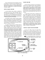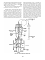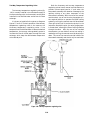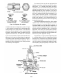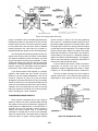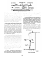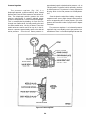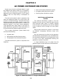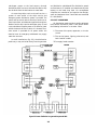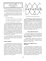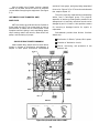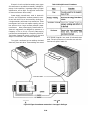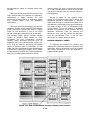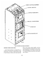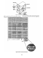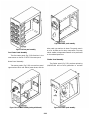
1
NONRESIDENT
TRAINING
COURSE
September 1996
Electronics Technician
Volume 8—Support Systems
NAVEDTRA 14093
DISTRIBUTION STATEMENT A: Approved for public release; distribution is unlimited.
Although the words “he,” “him,” and
“his” are used sparingly in this course to
enhance communication, they are not
intended to be gender driven or to affront or
discriminate against anyone.
DISTRIBUTION STATEMENT A: Approved for public release; distribution is unlimited.
PREFACE
By enrolling in this self-study course, you have demonstrated a desire to improve yourself and the Navy.
Remember, however, this self-study course is only one part of the total Navy training program. Practical
experience, schools, selected reading, and your desire to succeed are also necessary to successfully round
out a fully meaningful training program.
COURSE OVERVIEW: In completing this nonresident training course, you should be able to: describe
the different liquid cooling systems, dry air systems, ac power distribution systems, ship’s input systems in
terms of their different types, component parts, configuration, operation, and maintenance.
THE COURSE: This self-study course is organized into subject matter areas, each containing learning
objectives to help you determine what you should learn along with text and illustrations to help you
understand the information. The subject matter reflects day-to-day requirements and experiences of
personnel in the rating or skill area. It also reflects guidance provided by Enlisted Community Managers
(ECMs) and other senior personnel, technical references, instructions, etc., and either the occupational or
naval standards, which are listed in the Manual of Navy Enlisted Manpower Personnel Classifications
and Occupational Standards, NAVPERS 18068.
THE QUESTIONS: The questions that appear in this course are designed to help you understand the
material in the text.
VALUE: In completing this course, you will improve your military and professional knowledge.
Importantly, it can also help you study for the Navy-wide advancement in rate examination. If you are
studying and discover a reference in the text to another publication for further information, look it up.
1996 Edition Prepared by
ETC Richard E. Hippey Jr.
Published by
NAVAL EDUCATION AND TRAINING
PROFESSIONAL DEVELOPMENT
AND TECHNOLOGY CENTER
NAVSUP Logistics Tracking Number
0504-LP-026-7590
i
Sailor’s Creed
“I am a United States Sailor.
I will support and defend the
Constitution of the United States of
America and I will obey the orders
of those appointed over me.
I represent the fighting spirit of the
Navy and those who have gone
before me to defend freedom and
democracy around the world.
I proudly serve my country’s Navy
combat team with honor, courage
and commitment.
I am committed to excellence and
the fair treatment of all.”
ii
CONTENTS
Page
Chapter
1.
Liquid Cooling . . . . . . . . . . . . . . . . . . . . . . . . . . . . . . . . . . . 1-1
2.
Dry Air Systems . . . . . . . . . . . . . . . . . . . . . . . . . . . . . . . . . . 2-1
3.
AC Power Distribution Systems . . . . . . . . . . . . . . . . . . . . . . . .3-1
4.
Ship’s Input Systems . . . . . . . . . . . . . . . . . . . . . . . . . . . . . . . 4-1
5.
Information Transfer Systems
. . . . . . . . . . . . . . . . . . . . . ...5-1
Appendix
I.
II.
Glossary . . . . . . . . . . . . . . . . . . . . . . . . . . . . . . . . . . . . . . . AI-1
References . . . . . . . . . . . . . . . . . . . . . . . . . . . . . . . . . . . . ..
AII-1
INDEX . . . . . . . . . . . . . . . . . . . . . . . . . . . . . . . . . . . . . . . . . . . Index-1
iii
SUMMARY OF THE
ELECTRONICS TECHNICIAN
TRAINING SERIES
This series of training manuals was developed to replace the Electronics
Technician 3 & 2 TRAMAN. The content is directed to personnel working
toward advancement to Electronics Technician Second Class.
The nine volumes in the series are based on major topic areas with which
the ET2 should be familiar. Volume 1, Safety, provides an introduction to
general safety as it relates to the ET rating. It also provides both general and
specific information on electronic tag-out procedures, man-aloft procedures,
hazardous materials (i.e., solvents, batteries, and vacuum tubes), and radiation
Volume 2, Administration, discusses COSAL updates, 3-M
hazards.
documentation, supply paperwork, and other associated administrative topics.
Volume 3, Communication Systems, provides a basic introduction to shipboard
and shore-based communication systems. Systems covered include man-pat
radios (i.e., PRC-104, PSC-3) in the hf, vhf, uhf, SATCOM, and shf ranges.
Also provided is an introduction to the Communications Link Interoperability
System (CLIPS). Volume 4, Radar Systems, is a basic introduction to air
search, surface search, ground controlled approach, and carrier controlled
Volume 5, Navigation Systems, is a basic
approach radar systems.
introduction to navigation systems, such as OMEGA, SATNAV, TACAN,
and man-pat systems. Volume 6, Digital Data Systems, is a basic introduction
to digital data systems and includes discussions about SNAP II, laptop
computers, and desktop computers.
Volume 7, Antennas and Wave
Propagation, is an introduction to wave propagation, as it pertains to
shipboard and shore-based antennas.
Electronics Technicians, and
Volume 8, Support System, discusses system interfaces, sub-systems, dry air,
cooling, and power systems. Volume 9, Electro-Optics, is an introduction to
night vision equipment, lasers, thermal imaging, and fiber optics.
iv
INSTRUCTIONS FOR TAKING THE COURSE
assignments. To submit your
answers via the Internet, go to:
ASSIGNMENTS
The text pages that you are to study are listed at
the beginning of each assignment. Study these
pages carefully before attempting to answer the
questions. Pay close attention to tables and
illustrations and read the learning objectives.
The learning objectives state what you should be
able to do after studying the material. Answering
the questions correctly helps you accomplish the
objectives.
http://courses.cnet.navy.mil
Grading by Mail: When you submit answer
sheets by mail, send all of your assignments at
one time. Do NOT submit individual answer
sheets for grading. Mail all of your assignments
in an envelope, which you either provide
yourself or obtain from your nearest Educational
Services Officer (ESO). Submit answer sheets
to:
SELECTING YOUR ANSWERS
Read each question carefully, then select the
BEST answer. You may refer freely to the text.
The answers must be the result of your own
work and decisions. You are prohibited from
referring to or copying the answers of others and
from giving answers to anyone else taking the
course.
COMMANDING OFFICER
NETPDTC N331
6490 SAUFLEY FIELD ROAD
PENSACOLA FL 32559-5000
Answer Sheets: All courses include one
“scannable” answer sheet for each assignment.
These answer sheets are preprinted with your
SSN, name, assignment number, and course
number. Explanations for completing the answer
sheets are on the answer sheet.
SUBMITTING YOUR ASSIGNMENTS
To have your assignments graded, you must be
enrolled in the course with the Nonresident
Training Course Administration Branch at the
Naval Education and Training Professional
Development
and
Technology
Center
(NETPDTC). Following enrollment, there are
two ways of having your assignments graded:
(1) use the Internet to submit your assignments
as you complete them, or (2) send all the
assignments at one time by mail to NETPDTC.
Grading on the Internet:
Internet grading are:
•
•
assignment
Do not use answer sheet reproductions: Use
only the original answer sheets that we
provide—reproductions will not work with our
scanning equipment and cannot be processed.
Follow the instructions for marking your
answers on the answer sheet. Be sure that blocks
1, 2, and 3 are filled in correctly. This
information is necessary for your course to be
properly processed and for you to receive credit
for your work.
Advantages to
COMPLETION TIME
you may submit your answers as soon as
you complete an assignment, and
you get your results faster; usually by the
next working day (approximately 24 hours).
Courses must be completed within 12 months
from the date of enrollment. This includes time
required to resubmit failed assignments.
In addition to receiving grade results for each
assignment, you will receive course completion
confirmation once you have completed all the
v
PASS/FAIL ASSIGNMENT PROCEDURES
For subject matter questions:
If your overall course score is 3.2 or higher, you
will pass the course and will not be required to
resubmit assignments. Once your assignments
have been graded you will receive course
completion confirmation.
E-mail:
Phone:
[email protected]
Comm: (850) 452-1001, Ext. 1713
DSN: 922-1001, Ext. 1713
FAX: (850) 452-1370
(Do not fax answer sheets.)
Address: COMMANDING OFFICER
NETPDTC N315
6490 SAUFLEY FIELD ROAD
PENSACOLA FL 32509-5237
If you receive less than a 3.2 on any assignment
and your overall course score is below 3.2, you
will be given the opportunity to resubmit failed
assignments. You may resubmit failed
assignments only once. Internet students will
receive notification when they have failed an
assignment--they may then resubmit failed
assignments on the web site. Internet students
may view and print results for failed
assignments from the web site. Students who
submit by mail will receive a failing result letter
and a new answer sheet for resubmission of each
failed assignment.
For enrollment, shipping,
completion letter questions
grading,
or
E-mail:
Phone:
[email protected]
Toll Free: 877-264-8583
Comm: (850) 452-1511/1181/1859
DSN: 922-1511/1181/1859
FAX: (850) 452-1370
(Do not fax answer sheets.)
Address: COMMANDING OFFICER
NETPDTC N331
6490 SAUFLEY FIELD ROAD
PENSACOLA FL 32559-5000
COMPLETION CONFIRMATION
After successfully completing this course, you
will receive a letter of completion.
NAVAL RESERVE RETIREMENT CREDIT
ERRATA
If you are a member of the Naval Reserve, you
may earn retirement points for successfully
completing this course, if authorized under
current directives governing retirement of Naval
Reserve personnel. For Naval Reserve retirement, this course is evaluated at 3 points. (Refer
to Administrative Procedures for Naval
Reservists on Inactive Duty, BUPERSINST
1001.39, for more information about retirement
points.)
Errata are used to correct minor errors or delete
obsolete information in a course. Errata may
also be used to provide instructions to the
student. If a course has an errata, it will be
included as the first page(s) after the front cover.
Errata for all courses can be accessed and
viewed/downloaded at:
http://www.advancement.cnet.navy.mil
STUDENT FEEDBACK QUESTIONS
We value your suggestions, questions, and
criticisms on our courses. If you would like to
communicate with us regarding this course, we
encourage you, if possible, to use e-mail. If you
write or fax, please use a copy of the Student
Comment form that follows this page.
vi
Student Comments
Course Title:
Electronics Technician, Volume 8—Support Systems
NAVEDTRA:
14093
Date:
We need some information about you:
Rate/Rank and Name:
SSN:
Command/Unit
Street Address:
City:
State/FPO:
Zip
Your comments, suggestions, etc.:
Privacy Act Statement: Under authority of Title 5, USC 301, information regarding your military status is
requested in processing your comments and in preparing a reply. This information will not be divulged without
written authorization to anyone other than those within DOD for official use in determining performance.
NETPDTC 1550/41 (Rev 4-00
vii
CHAPTER 1
LIQUID COOLING SYSTEMS
Liquid cooling systems are vital to the proper
operation of shipboard electronic equipment. Because
of their importance, these cooling systems must be
reliable and readily available. Study the contents of this
chapter carefully. The knowledge you acquire may one
day help you prevent heat damage to a multimillion
dollar piece of equipment and the loss of countless
manhours being expended in its repair. Imagine how
you would feel if the damage occurred because you had
not checked a temperature gauge at a particular time
because you were not aware of its purpose or existence.
Knowledge of the equipment is one of the greatest
safeguards that you can develop. Let us begin by
discussing the methods for cooling electronic
equipments and systems.
ELECTRONIC EQUIPMENT
COOLING METHODS
Figure 1-1.-Convection cooling.
Most electronic equipment generates sufficient heat
so that some form of equipment cooling is required
during normal operation. Heat is generated by various
parts of the equipment because electrical energy is
dissipated in the form of heat whenever current flows
through a resistance. This heat must be removed to
prevent a change in the equipment’s operating
parameters and to prevent possible breakdown of
electronic parts.
upon the natural airflow and requires that the equipment
enclosure be of open construction without air falters.
To increase heat dissipation, a finned heat sink can
be added to the heat-producing part, as shown in figure
1-2. The fins increase the effective surface area of the
part, allowing more heat to be transferred to the air. For
the maximum transfer of heat, the part must make
contact with the heat sink. Silicone grease is usually
applied between the heat source and heat sink for better
thermotransfer. The heat sink must be kept free of any
dirt or dust, which would act as an insulator.
This section on liquid cooling systems describes
some of the more common methods of heat removal
from electronic equipment. It provides the basic
knowledge necessary for better understanding of the
major components, operation, and maintenance of a
typical cooling system. Our discussion will highlight
four methods of cooling: convection, forced-air,
air-to-air, and air-to-liquid.
CONVECTION COOLING
Cooling by the convection principle is shown in
figure 1-1. As the heat of an equipment part warms the
air in its vicinity, the warm air, being lighter, rises
through the outlet openings. The cooler air is drawn in
through the inlet openings to replace the warm air. This
method is limited in its cooling effect because it relies
Figure 1-2.—Finned best sink.
1-1
Figure 1-3.—Forced-air coding.
motor bearings or blower assembly is warranted at the
first sign of abnormal operation, such as excessive noise
or vibration. It is better to replace the bearings than to
risk damage to the equipment that the blower motor is
designed to protect.
FORCED-AIR COOLING
The increase the cooling effect over that provided by
convection cooling, forced-air cooling (fig. 1-3) uses a
blower to provide air movement instead of the natural
convection currents. Cool air is drawn into the
equipment enclosure and flows past the heat producing
part, picking up the heat. The air is then exhausted out
of the equipment. An air filter is provided at the air inlet
to remove dust and dirt that otherwise would settle on
the internal parts of the equipment. The air filter must
be kept clean according to the equipment’s maintenance
requirements. This will ensure maximum air movement
and cooling.
AIR-TO-AIR COOLING
Some units of electronic equipment are
hermetically sealed to prevent the entrance of moisture.
For equipment of this type, an air-to-air heat exchanger
(fig. 14) is used to prevent the air inside the equipment
enclosure from mixing with the outside air and still
allow cooling to take place. Air moving past the heat
producing part absorbs heat and is forced through a heat
exchanger by an internal blower. The heat in the internal
air is absorbed by the heat exchanger. The cooled
internal air is then returned to the equipment interior to
continue the cycle.
In some equipment, a honeycomb rf interference
filter is installed on both input and outlet to prevent stray
rf from entering or leaving the equipment cabinet. This
filter can also collect dirt that can reduce the airflow.
Failure of a bearing in the blower motor is not an
uncommon problem. A replacement of both blower
Figure 1-4.—Air-to-air cooling.
1-2
LIQUID COOLING
Heat is removed from the heat exchanger by forcing
cool outside air through the heat exchanger by an
external blower. There is no physical contact between
the internal and external air. In some applications, the
internal air is replaced by an inert gas such as nitrogen
to prevent oxidation.
Cooling systems are essential to the satisfactory
operation of all shipboard combat systems equipment.
In fact, some form of cooling is required for all
shipboard electronic equipment. As we have indicated,
liquid cooling is especially efficient for the transfer of
large amounts of heat. To maintain cooling systems,
you must have a broad understanding of the different
types of liquid cooling systems with which you are
involved.
AIR-TO-LIQUID COOLING
A more efficient heat transfer is possible by
replacing the air-to-air heat exchanger with an
air-to-liquid heat exchanger (fig. 1-5). In this method,
the internal air is also circulated past the heat producing
part and through a heat exchanger, but the heat is
removed from the heat exchanger by a liquid coolant
circulating through the heat exchanger.
A typical liquid cooling system is composed of two
basic coolant systems. First, there is the primary
system. It provides the initial source of cooling water
that can be either seawater (SW) or chilled water (CW)
from the ship’s air-conditioning plant, or a combination
of both. Next, the secondary system transfers the heat
load from the electronic equipment to the primary
system. The coolant normally used in the secondary
system is distilled water (DW). This distilled water is
ultrapure and is maintained in that state by a
demineralize. In some secondary systems, ethylene
glycol is added to the water to prevent freezing when the
system is exposed to freezing weather.
Air-to-liquid cooling systems usually employ
built-in safety devices to shut down the equipment to
prevent overheating.The overheating could be caused
by low or no liquid flow, liquid too hot, an inoperative
circulating fan, or reduced heat exchanger efficiency
because of improper maintenance.
This type of cooling system is normally found on
large equipment instillations where a huge amount of
heat is developed. Many radar transmitters, for
example, require cooling of this type. The other types
that we have discussed would not be able to dissipate
the heat that a high-powered radar transmitter develops.
A disadvantage of this type of cooling system is that they
are larger and more complex. However, for this reason
and because they are a part of the more complex
systems, we describe the typical liquid cooling system
used aboard ship. In this way, you will be given abetter
understanding of the function of individual components
within a system and the basic maintemnce required to
maintain the system to a high state of readiness.
TYPES OF LIQUID COOLING SYSTEMS
In the U.S. Navy, there are three basic
configurations of liquid cooling systems, and
conceivably you could be involved with all three. The
type or types with which you maybe involved, depends
upon the number and types of electronic equipment to
be cooled. The three types of systems areas follows:
Type I—Seawater/distilled water (SW/DW) heat
exchanger with SW/DW heat exchanger standby
Figure 1-5.—Air-to-liquid cooling.
1-3
requirements of the equipment. Some electronic
Type II—SW/DW heat exchanger with a chilled
water/distilled water (CW/DW) heat exchanger
standby
equipments require very close regulation of the
temperature of the distilled water; whereas, others do
not.
Type III—CW/DW heat exchanger with a
CW/DW heat exchanger standby -
Type I (SW/DW) systems are used for electronic
system installations that can be operated satisfactorily
The specifications for the type of system installed
on your equipment will depend upon the operational
with seawater temperature as high as 95°F. This should
Figure 1-6.—Type I liquid cooling system.
1-4
PRIMARY COOLING SYSTEM
result in a distilled water supply temperature to the
electronics of approximately 104°F. Type II (SW/DW,
The cooling water for the primary cooling system is
either seawater or chilled water. The seawater,
obviously, is from the sea and the chilled water is from
the ship’s air-conditioning plant. Figures 1-6,1-7, and
1-8 show the basic arrangements of systems using
seawater and chilled water.
CW/DW) systems are used in installations that cannot
accept a DW temperature higher than 90°F. Type III
(CW/DW) systems are used in installations where the
temperature range is critical. They require close
regulation of the DW coolant to maintain temperatures
between established limits. For example, the
In figure 1-6, seawater from a sea connection is
pumped by a seawater circulating pump in one of the
ship’s engineering spaces through a duplex strainer to
remove all debris and then through the tubes of a heat
exchanger. Finally, it is discharged back into the sea at
an overboard discharge. The seawater system shown in
figure 1-6 is a multiple-branch system. As such, it
supplies a number of heat exchangers for electronic
equipment. To regulate the proper amount of seawater
to each cooling system, an orifice plate is installed in the
line between each heat exchanger and the duplex
strainer. The heat exchangers are referred to as
seawater-to-distilled-water heat exchangers.
temperature limits might be 70°F and 76°F. As you can
see, Type III systems are used where tighter control is
required.
Liquid cooling systems are composed of piping,
valves, regulators, heat exchangers, strainers,
circulating pumps, expansion tanks, gauges, and a
demineralize. In some systems, there are specialized
components to monitor cooling water to the electronic
equipment. Let’s examine this in greater detail by
discussing the operation of the three types of liquid
cooling systems. Before doing so, however, let’s look
at the systems in terms of primary and secondary
systems.
Another means of providing seawater is through the
ship’s firemain, as shown in figure 1-7. The seawater is
Figure 1-7.—Type II liquid cooling system.
1-5
Figure 1-8.—Type III liquid cooling system.
systems. The chilled water is used as a backup source
of cooling water for the primary cooling system shown
in figure 1-7, and as a normal and backup source in the
system shown in figure 1-8. The chilled water flows
through the tubes of the heat exchanger (chilled water
to distilled water), a flow regulator, and back to the
chilled-water system. A temperature regulating valve at
the inlet of the heat exchanger regulates the flow of
chilled water through the heat exchanger to maintain the
required water temperature in the secondary system
(distilled water). The ship’s air-conditioning,
chilled-water circulating pump is used to pump the
chilled water through the heat exchanger. The
chilled- water system is a closed-loop water system
because the water is recirculated. It must be kept tight
and free from leaks to assure satisfactory operation.
taken from the firemain through a duplex strainer and a
flow regulator (orifice plate) to and through the heat
exchanger. It is then discharged overboard. The
connection to the firemain is permanent.
The ship’s fire pump, not shown in figure 1-7, is
used to pump seawater into the firemain. The fire pump
is similar in design to the previously mentioned seawater
circulating pump, except it has a much larger capacity.
Another means of getting seawater as a primary
coolant is by an emergency connection (figs. 1-6 and
1-7). This method is used if the normal seawater supply
is lost. The connection is usually by means of a 1-inch
fire hose. The emergency supply comes from an
alternate portion of the ship’s firemain or a portable
pump rigged by the ship’s damage control party. The
portable emergency hose is normally stored in the liquid
coolant machinery room.
SECONDARY COOLING SYSTEM
Note: Seawater systems are referred to as
open-looped or one-pass because the seawater flows
through the system only once.
The secondary cooling system is designed to
transfer heat from the electronic equipment being
cooled to the primary cooling system. This system is
usually comprised of a distilled- water circulating pump,
a compression or gravity-feed expansion tank, the
In figures 1-7 and 1-8, chilled water is taken from
the supply main of the air-conditioning, chilled-water
1-6
TYPE II COOLING SYSTEM
electronic equipment being cooled, a demineralize, a
temperature control valve, monitoring equipment with
its associated alarms, and the heat exchanger, which is
shared with the primary system. The secondary system
is a closed-loop water system, as compared to the
seawater system, which is a one-pass or open-loop
system.
‘he secondary system of the Type II cooling system
(fig. 1-7) is similar to the Type I secondary coolant
system and uses many of the same components. The
major difference is in the operation of the CW/DW heat
exchanger. The secondary coolant is in series with the
SW/DW heat exchanger and automatically supplements
the cooling operation when the SW/DW heat exchanger
is unable to lower the temperature of the distilled water
to the normal operating temperature. The CW/DW
temperature regulating valve allows more chilled water
to flow in the primary cooling system to the CW/DW
heat exchanger. This causes the temperature in the
secondary system to go down. Normally, this action
only occurs in the event of high seawater temperatures
encountered in tropic waters. The CW/DW heat
exchanger is also used in the event of an SW/DW heat
exchanger malfunction.
TYPE I COOLING SYSTEM
We are now ready for a more detailed look at the
types of cooling systems. Let’s begin by looking at the
Type I system. Starting with the distilled water pumps
(fig. 1-6), distilled water under pressure flows to the
temperature regulating valve. The temperature
regulating valve is installed to partially bypass distilled
water around the seawater- to-distilled-water heat
exchanger so that a constant water temperature can be
supplied to the electronic equipment. As the
temperature in the distilled water increases, more water
is directed to the heat exchanger and less to the bypass
line. ‘his maintains the output water temperature
constant. The standby heat exchanger is usually of the
same design and is used when the online heat exchanger
is inoperable or experiencing maintenance.
TYPE III COOLING SYSTEM
The Type III secondary cooling system (fig. 1-8)
also operates in a similar manner to the Type I system.
The major difference is in the way that the temperature
of the secondary coolant is regulated. A three-way
temperature regulating valve is not used. A two-way
temperature regulating valve is used in the primary
cooling loop to regulate the temperature of the
secondary loop.
The size of the heat exchanger is designed to handle
the full cooling load of the electronic equipment plus a
20 percent margin. From the heat exchanger, the water
then goes through various monitoring devices, which
check the water temperature and flow. These two things
depend upon the requirements of the electronic
equipment being coded. After the water moves through
the equipment, it is drawn back to the pump on the
suction side. In this way, a continuous flow of coolant
is maintained in a closed-loop system.
The duplicate CW/DW heat exchanger is installed
parallel to the first heat exchanger and is used as a
standby heat exchanger. In the event that a malfunction
occurs requiring the first heat exchanger to be removed
from service, the standby exchanger can be put into
service by manipulating the isolation valves associated
with the two heat exchangers.
An expansion tank is provided in the distilled water
system to compensate for changes in the coolant
volume, and to provide a source of makeup water in the
event of a secondary system leak. When the expansion
tank is located above the highest point in the secondary
system and vented to the atmosphere, it is called a
gravity tank. If it is below the highest point in the
secondary cooling system, then it is called a
compression tank, because it requires an air charge on
the tank for proper operation.
COOLING SYSTEM COMPONENTS
You should be able to identify and describe the
operation of the individual components of a typical
cooling system. This will help you to perform the
required system maintenance and trouble isolation. You
should never neglect the cooling system, because it will
quickly deteriorate to a point where only extreme and
costly maintenance will restore the system to its proper
performance.
‘The demineralize is designed to remove dissolved
metals, carbon dioxide, and oxygen. In addition, a
submicron falter (submicron meaning less than one
millionth of a meter) is installed at the output of the
demineralizer to prevent the carry-over of chemicals
into the system and to remove existing solids.
HEAT EXCHANGERS
In the liquid coolant heat exchangers, heat that has
been absorbed by distilled water flowing through the
1-7
Figure 1-9.-Single-pass SW/DW heat exchanger with double-tube sheets.
along the inside of the shell from inlet to outlet. In figure
1-9, the preferred method of double-tube sheet
construction is shown. Single-tube sheet construction
is shown in figure 1-10.
electronic components is transferred to the primary
cooling system, which contains either seawater or
chilled water from an air-conditioning plant. In both
cases (figs. 1-9 and 1-10), the heat exchangers are of the
shell- and tube-type in which the secondary coolant
(distilled water) flows through the shell, while the
primary coolant (seawater or chilled water) flows
through the tubes.
Double-tube sheets are used at both ends of a tube
bundle. A void space between the sheets prevents
contamination of the distilled water and permits the
monitoring of water loss because of tube leakage. You
should be on the lookout to detect leakage at the “telltale
drains,” which indicates a failure of a tube joint. The
type of water leaking out indicates whether the failure
is in the primary or the secondary system. The telltale
drains should never be plugged or capped off. A leak in
one of the tubes shows up as a loss of water in the
secondary side of the liquid coolant system, because it
operates at a higher pressure than the primary side. his
is intentional. This ensures that the distilled water is not
contaminated with seawater when a leak develops in a
heat exchanger.
A single-pass counterflow heat exchanger (fig. 1-9)
is more efficient than the double-pass heat exchanger,
because there is a more uniform gradient of temperature
difference between the two fluids. In figure 1-9, the
primary coolant (SW/CW) flows through the tubes in
the opposite direction to the flow of the secondary
coolant (DW). Heat transfer occurs when the seawater
flows through the tubes; extracting heat from the
distilled water flowing through the shell side of the heat
exchanger. The distilled water is directed by baffles to
flow back and forth across the tubes as it progresses
Figure 1-10.—Two-pass SW/DW beat exchanger with single-tube sheets.
1-8
ensure that tools, such as screwdrivers and wire brushes,
are not used in such a way that they may scratch or mar
the tube surfaces.
A double-pass heat exchanger is generally used
when there is limitation on the installation of the heat
exchanger. This type of heat exchanger is less efficient
than a single-pass exchanger and is subject to internal
undetectable leakage across the flow divider in the
inlet-outlet water box.
Over a period of time, electrolysis, which results
because of dissimilar metals in the cooling system, will
slowly dissolve the insides of various components in the
primary seawater cooling system. (Electrolysis is not a
problem in chilled water systems to the extent that it is
in seawater systems.) The type of metal used in the
fabrication of the heat exchanger tubes is the deciding
factor as to the use of zincs anodes or zincs. Zincs are
disks, rods, bars, or plates made of zinc metal that are
installed inside the heat exchanger’s water boxes. When
zincs are installed, the electrolytic action is concentrated
on the zinc and not on the metal of the heat exchanger
tubes. As electrolysis dissolves the zincs instead of the
heat exchanger tubes, they should be replaced. (The
purity of distilled water inhibits electrolysis in the
secondary system.) In an older cooling system, you
should be on the lookout for thin pipes in the seawater
side of the cooling system. You can check forbad pipes
by gently tapping the empty pipes with the ball of a
ball-peen hammer. A bad piece of pipe will make a dull
sound and dimple as it is struck lightly. This work
should be scheduled for overhaul while the ship is
inport.
It is to your advantage to maintain a log on the
performance of the heat exchangers installed in the
cooling systems with which you are involved. By
recording the operating characteristics, you will have
the data you will need to later analyze the performance
of the heat exchanger. The performance is monitored
by observing the temperature gradient (AT) between the
inlets and outlets of the two fluids. The overall
effectiveness of a heat exchanger is determined by
comparing its primary inlet temperature to its secondary
outlet temperature. For example, with no change in the
primary or secondary flow and if the heat transfer
capacity of the heat exchanger drops, the AT will
increase. By comparing the AT readings taken
periodically with the clean heat exchanger AT readings,
you can detect the deterioration of a heat exchanger
because of fouling. By maintaining a record of both
input and output pressure gradient
you will be able
to determine which side of the heat exchanger is fouled.
Heat exchangers must periodically be cleaned. The
secondary section (distilled water) is cleaned by
circulating chemicals through the secondary cooling
system to remove any buildup of scale deposits, which
accumulate on the surface of the tubes. The procedure
for routine cleaning of the primary section of the heat
exchanger is to first secure the sea connections to
prevent flooding. In some cases, an inspection port in
the water box can be opened to remove any foreign
matter lodged inside and against the tubes. If you are
unable to get at the ends of the heat exchanger to remove
the water boxes, then you must remove the heat
exchanger from its location and place it on the deck or
a suitable work surface. Mark each unit removed so that
it can be positioned in its proper place during
reassembly. With the water boxes removed, an air lance
should be passed through each tube and the passages
washed out. Where severe fouling exists, a water lance
should be pushed through each tube to remove foreign
matter attached to the tube walls. Where extreme
fouling exists, special cleaning equipment operated by
personnel skilled in their use is required. The ship’s
engineering officer is the best person qualified to
determine which procedure to use and whether the job
can be performed aboard ship or if it must be transferred
to a repair facility. You should take precautions to
The heat exchangers in the distilled water cooling
systems that cool electronic equipment are either
liquid-to-air or coolant-jacket type of heat exchangers.
The liquid-to-air heat exchangers are mounted inside
cabinets containing the heat-producing electronic
components. A cabinet fan circulates the air across the
heat exchanger and to the heat source in an airtight
circuit. In the coolant-jacket type of heat exchangers,
the distilled water is circulated through an integral water
jacket in a large heat-producing component such as a
power-amplifier tube, a plate transformer, or load
isolators. Vent and drain connections are provided to
permit the venting of trapped air and the draining of
water. Temperature gauges may be provided in the inlet
and outlet piping to check the performance of the heat
exchanger. Label plates indicate the water flow
direction through each cabinet. Flow regulators (orifice
plate or constant-flow device) usually provide a
constant flow of coolant to the individual component,
cabinet, or bay of electronic equipment to be cooled. On
critical electronic components that would be damaged
without coolant to remove the heat, coolant flow and
temperature switches monitor the coolant.
1-9
EXPANSION TANK
four-fifths full. The glass should be redlined at
four-fifths of the tank capacity. A vent pipe is located
on the top of the tank to prevent air pressure from
building up in the system. A valve and funnel
connection with cap is located on the top of the tank to
provide a means for filling the system with distilled
water. A low-level alarm switch is usually set at 20
percent of tank capacity. When the fluid level in the tank
lowers to 20 percent of the full level, visual and audible
alarms actuate at the alarm switchboard to warn
personnel when the system is low on distilled water. If
the tank should run out of water, then air is drawn into
the system, which results in increased corrective
maintenance on the system to remove the trapped air or
possible pump damage and/or failure of high power
transmitter components.
The expansion tank serves a threefold purpose in a
liquid cooling system. First, it maintains a positive
pressure required on the circulating pump inlet for
proper operation of the circulating pump. Second, the
expansion tank compensates for changes in the coolant
volume because of temperature changes. Third, it vents
air from the system and provides a source of makeup
coolant to compensate for minor losses because of
leakage or losses that occur during the replacement of
radar equipment served by the system. The tank maybe
either a gravity tank or a pressurized tank.
When an expansion tank is used as a gravity tank
(fig. 1-11), it is located above the highest point in the
distilled water system.
This provides sufficient pressure to the suction side
of the circulating pump. This also ensures a flow of
water from the tank into the system when makeup water
is required. The tank is provided with a sight glass to
check the level of water in the tank. The sight glass
should normally show the tank to be two-thirds to
The pressurized expansion tank (fig. 1-12) is
normally located near the circulating pump suction in
the return main of the secondary liquid cooling system.
The pressurized tank is airtight and is charged with
compressed air to an appropriate pressure from the
ship’s low-pressure air system. In some systems, a hose
Figure 1-11.-Gravity expansion tank.
Figure 1-12.—Pre-ssure expansion tank.
1-10
tested for chloride by the ship’s water test facility before
any of the water is used in the cooling system. The
maximum permissible level of chloride is .065 epm
(equivalent parts per million). The supply system
provides an alternate source of makeup water.
is used to pressurize the tank through a quick disconnect
or Schrader valve.
In other systems, a permanent pipe installation is
connected to the expansion tank through a
pressure-relief valve and an air shutoff valve. The ship’s
low-pressure air system is used to charge the pressure
tank, and then it is secured to prevent a possible
floodback of coolant into the low-pressure air system.
The relief valve is provided to protect the tank and
distilled water system from being overpressurized. The
sight glass and the low-level alarm switch function the
same as those on the gravity expansion tank.
The expansion-tank sight glass is your best
indication of a coolant leak in the secondary cooling
system. When the system uses excessive makeup water,
you should inspect the whole secondary system,
including the telltale drains on the heat exchanger, to
locate the source of the leak. A small drip can amount
to several gallons of water a day. On the pressurized
expansion tank, a very small air leak indicated by a
pressure drop on a tank gauge can be located by brushing
on a leak detector (a thick, clear, soapy liquid such as
concentrated liquid dishwasher soap) over the suspected
area of the leak. The escaping air causes bubbles to form
in the leak detector.
In both types of expansion tanks, the bottom of the
tank is connected by piping to the return main of the
secondary cooling system (fig. 1-6). Changes in coolant
volume causes the coolant to flow into or out of the
reservoir as necessary to maintain a stable, liquid
coolant, return-line pressure.
SEAWATER STRAINERS
Makeup water (distilled water) is added to the
expansion tank through the funnel located on the top of
the tank (fig. 1-11 and 1-12). A funnel cap is provided
for the funnel to prevent dirt from entering the system
through the funnel. Whenever you fill the pressurized
expansion tank, you have to first isolate the tank from
the cooling system and the air supply, then vent the air
pressure off through the vent pipe located at the top of
the tank. The makeup water can be obtained directly
from the ship’s evaporators and preferably when the
ship is making boiler feed water, because the water is
double distilled. At NO time should potable (drinking)
water or treated boiler feed water be used in any
electronic cooling systems. After the water is drawn
from the ship’s evaporators, it should be transported
using only a clean capped container. You should take a
sample of the water from the containers and have it
Strainers are used in the seawater cooling system to
remove debris and sea life, which could clog the
pressure and flow control device (orifice) and/or the
tubes of the heat exchanger. The two types of in-line
seawater strainers most commonly used in weapons
cooling systems are the simplex (single) and duplex
(double) basket strainers.
The simplex basket strainer (fig. 1-13) consists of a
Y-pattern body housing a wire mesh basket. Some
simplex strainers have a small drain on the cover to
allow you to drain the water off before removing the
cover. The basket is removed periodically for cleaning
and inspecting for deterioration. This type of strainer
requires that the seawater be secured before you clean
the basket.
Figure 1-13.-Seawater simplex strainer.
1-11
always be checked for proper spring-handle pressure
against the top of the basket cover. You should use only
the correct gasket material for the basket covers, as
specified in the COSAL. Inferior material can stretch
and be forced out from under the cover, and then
seawater could spray out and possibly flood the space.
The duplex strainer (fig. 1-14) consists of two
removable baskets located in parallel at the seawater
inlet. Seawater flows into the top of one basket and out
through the perforated sides to the outlet. This
arrangement allows maintenance to be performed on
one basket while the system is in operation, A selector
valve is arranged so that with the handle in one position,
seawater flows through one of the baskets, leaving the
other basket accessible for removal and cleaning. By
switching the valve handle to the alternate position, flow
is shifted over to the other basket.
TEMPERATURE REGULATING
VALVES
The temperature regulating valve regulates the
amount of cooling water flowing through or bypassing
a heat exchanger to maintain a desired temperature of
distilled water going to the electronic equipment.
Temperature regulating is usually provided by either a
three-way or a two-way temperature regulating valve or
a combination of both valves, as shown in figure 1-7.
The three-way valve is used where seawater is the
primary cooling medium in the heat exchanger, and the
two-way valve is used where chilled water is the primary
cooling medium.
A duplex pressure gauge monitors the differential
pressure between the inlet and outlet ports of the duplex
strainer. The purpose of the duplex gauge is to provide
a visual indication of a clogged strainer basket. To
correctly use the gauge, it should be marked when the
basket is clean. When the basket is clogged, the pressure
reading is usually 5 to 10 psi above the clean-basket
reading. If the pressure drop is less than the
clean-basket reading, a check should be made for a
damaged basket or missing basket.
Three-Way Temperature Regulating
Valve
The basket handle (spring handle) acts as a
spring-load to seat and hold the basket in the housing.
A damaged spring handle will permit debris to bypass
the strainer basket and clog the heat exchanger tubes. In
some cases, the basket may spin inside the duplex
strainer and physically wear away the basket seat and/or
the side of the duplex strainer. The duplex strainer
would then have to be removed for extensive repairs,
possibly off ship. New or replacement baskets should
The three-way regulating valve (fig. 1-7) is installed
so that the incoming distilled water to the valve can be
directed to the heat exchanger or caused to bypass the
heat exchanger. More accurately, the distilled water is
proportioned between these two paths. The valve
senses the temperature of the distilled water
downstream of the junction between the heat exchanger
Figure 1-14.-Seawater duplex strainer.
1-12
outlet and the bypass and then proportions the two flows
to obtain the desired temperature. The three-way
regulating valve’s range of operation is within
degrees of the setting on the valve.
Refer to figure 1-15 for the following description of
the operation of the three-way regulating valve.
The bulb contains a volatile liquid that vaporizes
and expands when heated. The generated pressure in
the bulb is a function of the temperature around it. This
pressure is transmitted through capillary tubing to the
flexible bellows, which are loaded by the spring. Both
bellows and spring rest on the end of the valve stem.
Expansion or contraction of the bellows causes
movement of the stem and the piston in the valve body.
The flow of the liquid entering the valve at port A is
proportioned between ports B and C in the proper ratio
to maintain the mixed flow temperature at the valve’s
set point. Total flow through the valve remains
constant. Movement of the bellows is opposed by the
spring, which is provided with a means to adjust the
operating temperature by the spring-tension adjustment
wheel. A drop in temperature at the thermostatic bulb
reduces the pressure in the thermostatic assembly,
causing it to exert less force, resulting in an upward
movement of the stem because of the force of the spring.
As the stem is connected to the piston, the piston also
moves upward, enabling more liquid to pass from the
bottom inlet through the right outlet (bypass) side and,
at the same time, restricting flow through the left outlet
(heat exchanger) side. A rise in temperature at the
thermostatic bulb results in a reversed effect.
Figure 1-15.—Three-way temperature regulating valve.
1-13
Two-Way Temperature Regulating Valve
Both the three-way and two-way temperature
regulating valves have a manual override feature to
provide uninterrupted service, if and when the
thermostatic assembly fails because of damage to the
capillary tubing or any other component of the
thermostatic assembly. With the use of the manual
override wheel, you can set the valve plunger/piston in
the required position to operate the liquid cooling
system by turning the manual override wheel down
(from right to left) until it touches the spiral pin in the
valve stem. Beyond this point, the valve plunger/piston
is forced down, allowing the flow of cooling medium
through the valve. With the use of the installed
thermometers, you can decide if more or less cooling is
needed by turning the manual override wheel up or
down. The use of the manual override inhibits the
thermostatic assembly and should only be used when
The two-way temperature regulating valve (fig.
1-16) is normally installed in the chilled water supply to
the heat exchanger with the thermostatic sensing bulb
installed in the distilled water outlet from the heat
exchanger.
It is shown as installed in the system on diagrams
figures 1-7 and 1-8. The basic operation of the two-way
temperature regulating valve is the same as the
three-way temperature regulating valve. If the
temperature of the distilled water is above the desired
temperature, the two-way valve gradually opens to
increase the flow of chilled water through the heat
exchanger, which keeps the distilled-water temperature
at the desired point.
Figure 1-16.—Two-way temperature regulating valve.
1-14
the thermostatic assembly is inoperable. Corrective
maintenance of the regulating valve consists of
inspecting the valve for leaks and for freedom of stem
movement, adjusting the set point at which the valve
regulates, renewing the thermostatic assembly, and
cleaning and restoring valve parts. Any time that you
remove a valve, you should center punch a dot code on
each piece to ensure that the valve and piping are
installed in the original configuration. The three-way
valve can be turned around, and the problem could go
unnoticed until you try to align the temperature
regulation of the cooling system. There are individual
manuals for the temperature-regulating valves and they
should be closely followed. For example, if you remove
the top of the thermostatic assembly without chilling the
temperature probe, the bellows will expand and rupture,
making the unit worthless. To verify that the
thermostatic assembly has failed, close valves upstream
and downstream of the thermostatic bulb, drain the unit
below the location of the bulb, and remove the bulb from
its well. Place the bulb in a suitable vessel and observe
the valve stroke while the bulb is alternately heated with
hot water and cooled with cold water. If the valve
thermostatic assembly does not respond, it has lost its
thermostatic charge, and a new unit must be installed.
on the expansion tank sight glass. To stabilize the flow
of seawater and to prevent jet erosion of the heat
exchanger and associated piping, the orifice plate should
be installed with at least 15 pipe diameters of straight
pipe upstream from the heat exchanger. When there is
a drop in the heat exchanger primary input pressure and
the seawater supply pressure has not changed, you
should first check the duplex strainer differential
pressure gauge to ensure that the duplex strainer is clean.
Then the orifice plate should be inspected for deposits
or particles that could restrict the seawater flow. You
should also inspect the orifice plate for erosion damage
of the hole diameter. The orifice plate should be
replaced when there is an increased flow of seawater to
the point that it could damage the heat exchanger. Never
use the seawater valves to throttle (partially closed) the
flow of seawater in the primary cooling system, because
the seawater will erode the internal parts of the valve.
The damage to the valve would require extensive repair
or replacement, because the valve would no longer close
properly.
When used with the chilled-water system, the
constant flow regulator (variable orifice, fig. 1-17) is
installed downstream from the heat exchanger. This
restricts the flow from the heat exchanger and keeps the
heat exchanger fully submerged for greater efficiency
(heat transfer). This type of flow regulator is not used
in the seawater system because the internal parts would
easily become fouled with marine growth and deposits.
The operation is dependent on the movement of the
orifice plugs (neoprene) to regulate the flow of water.
FLOW REGULATORS
You will encounter many different types and sizes
of flow regulating devices used in both the primary and
secondary cooling systems. They are used to reduce the
pressure or the flow of coolant through a cooling system.
Another type of flow-regulator valve (equipment
flow) used primarily with electronic equipment to
regulate the flow of distilled water through the
The orifice plate is found primarily in the seawater
cooling system. It is the simplest design of a flow
regulating device, consisting of a steel plate with a hole
in it. With constant known seawater pressure and with
a given hole size, the volume of water through the device
can be determined. The use of an orifice plate is limited
to where the input water pressure is essential y constant,
such as the ship’s firemain. The orifice plate is normally
installed between two pieces of flanged pipes upstream
from the heat exchanger as shown in figures 1-6 and 1-7.
This will reduce the ship’s firemain pressure below the
pressure in the secondary cooling system. As we have
indicated earlier, should one of the heat exchanger tubes
fail, the seawater pressure is lower than the distilled
water pressure; therefore, it would not contaminate the
secondary cooling system. The secondary cooling
system would force distilled water into the primary
cooling system. A ruptured heat exchanger tube or a bad
single tube sheet in a heat exchanger would give no
visual indication of water loss except for the indication
Figure 1-17.-Constant flow regulator.
1-15
The nominal flow rate of the equipment-flow
regulator can be from one-half to more than 12 gallons
per minute. It is normally used with a pressureregulating valve. You should be aware that this type of
regulator can deteriorate over time. The insert can
become distorted and cause a reduction in the flow of
water. With a drill index set, you can use the back of a
drill bit to measure the hole size and compare it to a
known good constant-flow regulator or the equipment
manual. Do not drill out the insert to restore it to the
proper size, because it will become distorted. Its
distorted shape would prevent the insert from regulating
the distilled water flow.
The pressure-regulating valve (fig. 1-19) is used to
regulate a major section of the coolings system; whereas,
the flow regulator is normally used to regulate an
individual feeder line to an individual component or
cabinet. The pressure-regulating valve usually has a
pressure-relief valve downstream from it to protect the
equipment from being over pressurized. Should a
failure occur in the pressure regulating valve, the
pressure-relief valve would keep the water pressure at a
safe level to prevent equipment damage.
Figure 1-18.—Equipment flow regulator.
individual cabinets and components is shown in figure
1-18. It maintains a constant flow of distilled water with
limited changes in the input pressure. At the minimum
water flow, the total amount of water is passed through
the device. As the flow of water increases to the flow
regulators maximum limit, the water flow is restricted
by the insert’s movement, which causes the hole size to
decrease. In this way, the flow of water is regulated.
The amount of water that the flow regulator will pass is
usually stamped on the side of the regulator. This is
because the external dimensions are usually the same
for differently rated regulators.
The operation of a typical pressure-regulating valve
is as follows: When a drop in downstream (outlet)
pressure occurs, the pressure in the diaphragm chamber
is lowered concurrently. The downstream side of the
valve is connected to the diaphragm chamber through a
narrow opening along the periphery of the piston. The
Figure 1-19.—Pressure regulator.
1-16
Figure 1-20.-Cooling system flow switch.
switch is shown in figure 1-20. The main operating
parts consist of a hermetically-sealed reed switch and a
permanent magnet attached to an internal shuttle. With
the proper flow of coolant, the shuttle moves the magnet
up and away from the reed switch. This keeps the reed
switch contacts open, When the coolant flow drops
below the minimum for a flow switch, the shuttle is
forced down by the spring to a balanced condition
against the flow of the distilled water. The magnetic
field is now close enough to cause the reed switch to
close and activate the low-flow alarm.
spring is allowed to force the diaphragm downward
releasing the tension on the rocker arm, and the inlet
pressure opens the valve. The outlet pressure increases
to the preset level, and the static control chamber
pressure balances the valve spring to maintain a
regulated downstream pressure to the served equipment.
You should take the following precautions with this
type of valve. Ensure that the locknut is loose before
you adjust the adjusting screw; otherwise, you could
strip the threads of the brass spring chamber. If water
should start leaking out of the vent, the valve should be
serviced for a leaking diaphragm. This should be done
before it ruptures. The vent should never be plugged or
painted over. Either would inhibit its operation.
A much smaller flow switch is used in electronic
equipment to monitor the flow to individual
components. Atypical equipment flow switch is shown
in figure 1-21. The one depicted contains a fixed orifice.
If you should remove a flow regulator or a pressure
regulator, make certain that you reinstall it correctly,
because it can be installed backwards. Look for an
arrow for direction of flow or the inlet and outlet
stamped on the body of the device. Pipe-joint sealant
should be used only on the male pipe threads and not
closer than one thread to the open end to seal the device.
Improper use of anti-seize tape can result in the tape
being cut loose and circulated in the cooling system,
which could plug up a small component.
The flow of water through the orifice causes a
pressure drop across it. This pressure drop causes the
diaphragm to move against the spring. When the
FLOW MONITORING DEVICES
Most systems incorporate one or more types of
devices to monitor the flow of distilled water through
the system to ensure that the electronic equipment is
supplied with an adequate flow. A low-flow switch is
normally found in the secondary cooling system to
monitor the overall coolant flow. It is electrically
connected to a common alarm circuit to warn personnel
when the system flow rate drops below a specified
minimum value. A typical cooling system low-flow
Figure 1-21.—Equipment flow switch.
1-17
Figure 1-22.-Venturi flowmeter.
differential pressure (pressure drop) is sufficient, the
microswitch will activate to indicate that the switch has
the proper flow through it. You should be sure that the
flow switch is defective before overhauling or replacing
it. The problem could be a partially closed supply/return
valve, obstruction in the coolant line, insufficient
coolant pressure, or many other things. By using the
coolant system pressure gauges and/or the installation
of a permanent or a temporary in-line flowmeter, you
should be able to correctly isolate the problem.
pressure taps. A calibration chart is usually supplied
with the flowmeter to convert the differential pressure
to gallons per minute (gpm), or the face of the meter may
indicate readings in gpm.
The orifice flowmeter works in the same manner as
the venturi flowmeter, but its construction is much
simpler and less expensive to manufacture. In place of
the tapered throat, the orifice flowmeter uses a flat plate
with a hole in it, which causes a considerable loss of
pressure downstream. The efficiency of this type of
flowmeter can be as low as 65 percent.
In the secondary cooling system, a full-flow system
flowmeter (figs. 1-6, 1-7, and 1-8) is provided to enable
you to monitor the total system flow rate for
troubleshooting purposes. There are three types of
system flowmeters installed aboard ship. All of them
serve the same functional purpose of monitoring coolant
flow rate. You will encounter the venturi-type
flowmeter, orifice-type flowmeter, and the rotameter
flowmeter. Most systems incorporate one secondary
coolant flowmeter and one or more smaller flowmeters
to ensure that the electronic equipment is being supplied
with an adequate flow of coolant.
The rotameter (fig. 1-23) is a variable area orifice
meter that functions by maintaining a constant
differential pressure with varying flow. The rotameter
consists of a float positioned inside a tapered, tempered
glass tube by the action of the distilled water flowing up
In the venturi-type flowmeter (fig. 1-22), as the
coolant approaches the contracted portion (throat) of the
meter, its velocity must increase as it flows through the
contracted zone. The angle of approach is such that no
turbulence is introduced into the stream. A pressure tap
is located at the side wall in the pipe ahead of the meter,
and another one is located at the throat. The increase in
velocity of the coolant water through the throat results
in a lower pressure at the throat. The flow rate is
proportional to the difference in pressure between the
two taps. The gradual tapering of the meter walls back
to pipe size downstream of the throat allows the coolant
water to slowdown with a minimum of lost energy. This
allows a recovery of nearly 99 percent of the pressure
on the approach side.
To monitor the amount of flow through the
venturi-type flowmeter, a differential pressure gauge is
used to monitor the pressure difference between the two
Figure 1-23.—Rotameter.
1-18
velocity to the coolant. The impeller chamber collects
the high-velocity coolant from the impeller and guides
it to the pump outlet. A mechanical shaft seal is used to
eliminate external leakage. This seal is lubricated and
cooled by water ducted from a high-pressure zone of the
pump. You will find a vent valve located on the top of
the pump casing to remove air and ensure the pump is
primed with coolant.
through the tube. The flow restriction is the space
between the float and the tube wall. This area increases
as the float rises.
The differential pressure is fixed depending upon
the weight of the float and the buoyant forces resulting
from the combination of float material and the distilled
water’s specific gravity. The tapered tube of the
rotameter is usually glass with calibration marks reading
directly in gpm. The major advantage of a rotameter
over the venturi orifice meter is the visibility of the
coolant. This allows quick determination of excessive
entrained air in the coolant.
Located at the outlet of each pump is a check valve
to prevent coolant from the outlet side of the operating
pump from circulating to the return side of the coolant
system through the standby pump. Hand-operated
valves at the pumps are used to isolate the pumps so they
can be removed for maintenance.
CIRCULATING PUMP
Each secondary circulating pump is rated in gallons
per minute (gpm) output at a specified head pressure in
pounds-force per square inch gauge (psig) pressure, or
in feet of water. The rating is usually at the pump’s
maximum efficiency point, and it will vary depending
upon the pump design. On all pumps, as the output
pressure increases, the output flow decreases, and vice
versa. This relationship is almost linear but differs with
different pump designs. However, this condition means
that if a restriction is placed in the pump output lines,
the pressure will increase and the flow will decrease.
The restriction could be a partially closed hand valve,
dirty filter, damaged or crimped piping or hose, and so
forth. In figures 1-6, 1-7 and 1-8, the pump performance
indicators are the suction and discharge pressure gauges
and the system flowmeter. If you start a pump and
pressure fails to buildup, you should exhaust air through
the vent cock on the top of the pump casing. You should
ensure that the suction valve is fully opened and there is
Each cooling system has two secondary distilled
water circulating pumps (fig. 1-24), which are identical
in construction and capacity. One pump is designated
for service, and the other is held in standby in case the
designated pump fails. Should the pump designated for
operation fail, then the standby pump would be used in
its place. The pumps should be operated alternately
(every other week) to prevent deterioration of their shaft
seals, equalize wear, and permit PM actions to be
performed regularly.
The two circulating pumps used in the liquid
cooling system are single-stage centrifugal pumps
closely coupled (pump is built onto the motor) to a
constant-speed electrical motor. You may run into an
older system that uses a separate pump and motor joined
by a flexible coupling. The centrifugal pump has two
major elements—the impeller rotating on the extension
of the electric motor shaft and a casing that is called the
impeller chamber. The impeller imparts the initial
Figure 1-24.—Distllled water circulating pump.
1-19
minimize corrosion and the formation of scale on the
radar unit. Corrosion or scale on a high-heat-density
component such as waveguide dummy loads and
klystrons results in the formation of a thermal barrier.
The thermal barrier reduces the effectiveness of heat
transfer at normal operating temperatures. This leads to
premature failure of the components.
pressure on the pump suction pressure gauge. If flow
doesn’t develop, check for clogging and wear.
You should not operate a pump without collant
flow. Some pumps have a small recirculating line that
enables the pump to recirculate coolant from the
discharge side of the pump to the suction side. ‘This
provides for a flow of coolant through the pump if an
inlet/outlet valve to the pump is closed with the pump
running. Whatever the case, you should keep in mind
that the operation of a pump without the normal flow of
coolant through it will result in overheating and seizure
of the pump. Corrective maintenance of the circulating
pump consists of repairing leaks, replacement of the
mechanical seal, and cleaning the internal parts. This
type of maintenance is performed by personnel of the
ship’s engineering department. You should provide
assistance if it is needed.
DEMINERALIZER
The demineralize (figs. 1-6, 1-7, and 1-8) is
connected between the secondary cooling system
supply and return lines to circulate water through it. The
demineralize is sized so that 5% of the cooling system
volume passes through the demineralize every hour.
The coolant is purified by organic compound adsorption
(if required), oxygen removal, ion exchange processes,
and submicron filtration. Shown in figure 1-25 is a
typical three-cartridge demineralize. Some
demineralizes use only two cartridges; one of the
cartridges is a combination cartridge that provides
organic compound adsorption, if it is required.
The secondary cooling system water purity is
maintained in an ultrapure state by a demineralizer. By
maintaining the coolant at a high degree of purity, you
The input supply valve to the demineralize unit,
depicted in figure 1-25, must be adjusted on system
start-up, and periodically thereafter to maintain the
Figure 1-25.—Deminerlaizer.
1-20
resins exchange ions with the contaminates, thereby
removing them and leaving pure deionized coolant. You
should replace the mixed-bed cartridge when the purity
meter indicates a low outlet purity.
correct flow rate through the flowmeter. The high of a
flow rate can damage the cartridges. If the flow rate
cannot be increased to the proper rate with the inlet
supply valve fully open, you should check to ensure that
the outlet valve is fully open. The submicron filter is
used to remove small particles from the coolant flow
having a size greater than 0.5 micron. If the filter
becomes clogged, it also reduces the flow of coolant.
This necessitates a change of the filter cartridge or filter
sheet (membrane). To change the filter, the
demineralize valves must be properly positioned.
As indicated in figures 1-25 and 1-26, two
conductivity cells monitor the coolant through the
demineralize. The first cell measures the purity of the
coolant as it enters the demineralize. The second purity
cell is used to measure the purity of the coolant as it
leaves the demineralize. The conductivity cell consists
of two electrodes immersed in the coolant flow path.
The electrodes measure the conductivity of the coolant,
which varies with the amount of ionized salts dissolved
init. If the impurity content increases in the coolant, the
purity meter indicates higher conductance.
If the filter cartridge or membrane continually
becomes clogged (about one-half hour or less after
replacement), the usual cause in the distilled water
system is the presence of bacteriological impurities,
Bacteriological impurities introduced into the
secondary liquid cooling system using distilled water
may exist in the demineralize cartridges and/or the
whole secondary cooling system. If the bacteriological
impurities are in the whole secondary cooling system,
the growth rate in a warm water environment could be
of a magnitude that exceeds the capability of the
demineralize. You will have to determine the source
and magnitude of contamination. However, it should be
noted that bacteriological contamination in a secondary
cooling system that uses distilled water and ethylene
glycol is highly improbable.
On some purity meters, the purity of the coolant is
displayed as resistivity. In this type of meter, an increase
in the impurity of the coolant causes the meter to
indicate a low resistivity. Conductance is the reciprocal
of resistance, and is measured in micromhos/cm.
Resistivity is measured in megohms/cm. You can
convert from conductivity to resistivity by taking the
reciprocal of conductivity. Similarly, the reciprocal of
resistivity is equal to the conductivity. A comparison of
both ways of measuring the purity of the coolant is
Improper handling or storage of the cartridges could
cause the cartridge to be a source of contamination. You
should always store the cartridges in a cool, dry area.
Exposure to heat hastens the growth of any biological
contaminates that may have entered the cartridges. You
will encounter three different types of cartridges. The
first cartridge is the organic removal cartridge. It
contains granulated activated charcoal (carbon) that
removes large organic molecules and chlorine by
adsorption. It is always installed in the first exchanger
(if required) to prevent organic molecules from fouling
the remaining cartridges. The second cartridge is the
oxygen removal cartridge. It is composed of anion
resins that remove oxygen from the water by ion
exchange of sulfite ions to sulfate ions. By conducting
a standard oxygen test (or if the cooling system has an
oxygen analyzer installed), the quality of the outlet
water from the demineralize can be tested for oxygen
content so that you will know when to replace an oxygen
cartridge. When the oxygen cartridge is near
exhaustion, it will have a urine odor, which is given off
by the sulfate. The third cartridge is the mixed-bed
cartridge. It is filled with cation (positive charge) and
anion (negative charge) resins, which remove solids,
dissolved metals, and carbon dioxide. The charged
Figure 1-26.-Purity meter.
1-21
the meter to establish if the problem is in the purity
monitor. If the purity monitor does not have a test
feature, then use the calibration plug in place of one of
the conductivity cells to test the operation of the purity
meter. Most of the time, only routine maintenance is
required to return the demineralize to its normal
operating condition.
shown in table 1-1. The purity meter indications will
vary with ionized salt concentration and the temperature
of the coolant flowing through the cell. The temperature
effect is canceled by a built-in temperature
compensation circuit.
The inlet conductivity is compared to a preset value
of cell conductance to actuate an alarm circuit when the
purity of the water drops below the preset level. In
addition, the purity meter provides direct readings of the
water purity at the inlet and outlet of the demineralize.
Typical operating requirements for the demineralize
are conductivity 1 micromno/cm at 77°F (resistivity 1
megohm/cm at 77°F), oxygen content 0.1 ppm by
weight, and mechanical filtration 0.5 microns absolute.
Maintenance of the demineralize consists
primarily of the scheduled replacement of cartridges
(before they are exhausted) and clogged filters.
Obtaining satisfactory service life from the cartridges
and filters is largely dependent on minimizing external
contamination. Replacement cartridges must be kept
sealed and stored in a cool dry place until used. The
circulating system must be kept tight to reduce the need
for makeup water. Makeup water, in arty case, should
be as particle-free as possible and should not exceed
0.065 ppm chloride.
When water has been circulated through the system
for extended periods of time, a high resistivity or low
conductivity reading may be indicated on both input and
output samples. This condition is highly desirable and
indicates that all ionizable material has been properly
treated, and that the demineralize is maintaining a high
degree of purity. When a system is filled with a fresh
charge of water, it should be allowed to circulate for
approximately 2 hours before comparing the input and
output readings. During the initial circulation period,
the resistivity readings vary because of the mixing
action of water that has been treated by the
demineralize with the fresh charge of water. A properly
operating system can supply water of acceptable purity
in 4 to 8 hours. Water in a system that has been secured
for any length of time should be of acceptable purity
within 2 hours. The resistivity/conductivity reading
required for a specific installation must be maintained
for optimum operation of the cooling water system.
OXYGEN ANALYZER
In some secondary cooling systems, an oxygen
analyzer is installed to measure the amount of dissolved
oxygen in the liquid coolant. The presence of oxygen
causes oxidation that leads to the formation of scale in
the cooling system. An oxygen analyzer has an oxygen
sensor installed in the supply side of the secondary
cooling system. The sensor is an electrolytic cell in an
electrolyte solution or gel. A thin membrane covers the
end of the sensor, which is inserted in the coolant. This
membrane is gas permeable to the dissolved oxygen in
the secondary coolant. This allows the oxygen to pass
through the membrane. The oxygen reacts with the
electrolyte, which causes a proportional change in the
amount of current flow in the sensor. The sensor’s
electrical output is measured and displayed on the
oxygen analyzer’s meter. ‘The meter is calibrated to read
the oxygen content in parts per million or billion.
Your first indication of a problem in the
demineralize is usually indicated by abnormal purity
meter readings (too low or too high), an abnormal
flowmeter reading, and/or a light and audible warning
from the purity monitor. Some purity monitors
can be tested for accuracy by a built-in test function on
Table 1-1.—Distilled Water Resistivity Versus Conductivity
Data
Because of solid-state electronics and the few
components used, the oxygen analyzer requires very
little maintenance other than the cleaning and changing
of the electrolyte in the sensor. When the meter on the
analyzer requires frequent calibration because the meter
readings are drifting or changing sharply, you should
recognize that the analyzer has a bad sensor. When you
clean and recharge the sensor, use caution to prevent
contamination of the membrane from the oil on your
fingers.
1-22
COOLANT ALARM SWITCHBOARD
The cooling system alarm switchboard (SWBD)
monitors various conditions to alert you to a problem
that may develop in the cooling system. When an
abnormal condition occurs, the alarm SWBD indicates
the fault condition with both a visual and an audible
alarm. The alarm SWBD usually has several remote
bells and lights in CIC and other electronic spaces
aboard ship to indicate a fault condition. The alarm
SWBD is located in CIC or the coolant pump room.
There are several standard types of alarm switchboards
used throughout the Navy. A common type of alarm
SWBD is shown in figure 1-27.
Figure 1-27.-Cooling system alarm switchboard.
1-23
Also, a command is fed to the tone generator, producing
a pulsating alarm. This pulsating alarm signal informs
the operator that the selector switch should be returned
to the normal position.
On the main alarm panel, there are two GROUND
INDICATOR LAMPS (fig. 1-27) to indicate the
presence of a ground in the alarm system. All shipboard
alarm panels and remote sensors are electrically isolated
from the ship’s ground. The only exception is the
ground fault detector, which is connected to ground for
ground monitoring. If one of both lamps light, you
should have the alarm SWBD and its remote sensors
The AUDIBLE SILENCE CONTROL is a two-position
switch that permits silencing (VISUAL POSITION) the
audible alarm on the main panel. The ALARM lamp on
the main panel is lighted when the AUDIBLE SILENCE
CONTROL is placed in the VISUAL position, and the
system is in an alarm condition.
C U T O U T . With the selector switch in the
CUTOUT position, the upper lamp is out while the
lower lamp is steadily on. In this position, power is
removed from the sensor loop to facilitate maintenance.
TEST. This selector switch position simulates an
alarm condition. The upper indicator lamp will flash
while the lower lamp will remain off. A wailing alarm
is produced.
Your proper response to the coolant alarm SWBD
could mean the difference between a small service
problem or the markings of a much larger disaster. For
example, the COOLANT SUPPLY EXPANSION
TANK LOW-LEVEL alarm module senses a low
coolant level in the expansion tank, immediate action
must be taken. If the tank should empty, the pump will
draw air into the lines and force it throughout the
secondary cooling system. This would require
additional maintenance to correct the problem.
The lower half of the alarm panel (fig. 1-27) holds
the alarm modules that are connected through the alarm
panel to the remote sensors. On the panel depicted,
there are only five alarm modules used while the rest is
blanked off with covers. Should additional remote
sensors be installed at a later date, a new alarm module
is plugged into the lower panel for each sensor installed.
Each alarm module includes a center-divided lighted
display. Either half can independently display a steady
red light, a flashing red light, or no light, depending upon
the circuit logic. The six possible combinations of alarm
module lights and the appropriate audible alarm are
shown in figure 1-28. Located on the lower half of each
alarm module is a four-way position switch that allows
you to place the individual alarm module in the
following modes:
WAVEGUIDE FLOODING
An improperly maintained liquid cooling system
can cause a major disaster in your waveguide system, if
it is liquid cooled. The damage caused by waveguide
flooding can easily run into thousands of dollars and
include the expenditure of hundreds of manhours by
ship’s force.
NORMAL. This is the normal operation mode.
With the sensor contacts open, the upper indicator lamp
in the module will be on steady while the lower lamp is
off. If an alarm condition occurs, the sensor contacts
will close; the upper lamp will then flash while the lower
lamp remains off and an alarm command from the
module actuates a tone generator, producing a wailing
alarm. If the sensor loop is open-circuited, with the
selector switch in the normal position, the alarm module
signals a supervisory failure; in this case, the upper lamp
will be off while the lower lamp will be steadily on, and
the tone generator will come on, producing a pulsating
alarm.
Various components of high-powered radars, such
as dummy loads, load isolators, and circulators are
cooled by the use of liquid coolant. These components
use a ceramic plug (or disk) in a water-cooled load.
Transmitted rf energy passes through the plug and is
absorbed as heat by liquid coolant flowing through the
load. The plug acts as a window for rf energy, and at the
same time, forms a watertight seal between the
waveguide and the coolant jacket of the load.
Particles of oxidation and dirt from a dirty coolant
system can buildup on the coolant side of the ceramic
plug. The buildup can create an impedance mismatch
or hot spot. This condition can generate an arc, which
carbonizes the ceramic plug so that coolant can leak
through or around the carbonized plug.
This is the position for
STANDBY.
acknowledging an alarm. If the selector switch is
moved from the normal to the standby position during
an alarm condition, both the upper and lower indicator
lamps will be steadily on and the audible alarm will be
silenced. When the alarm condition is cleared with the
selector switch in the stand-by position, the lower lamp
changes to a flashing mode and the upper lamp goes out.
Since a nominal 80-psig pressure differential exists
between the coolant in the load and air in the waveguide,
coolant can flow from the water load into the
waveguide, resulting in waveguide flooding. Once the
1-24
Figure 1-28.—Alarm switchboard visual displays and audible alarms.
ISOLATE EXTENT OF FLOODING
coolant has entered the waveguide, it can flow
through the various sections of the waveguide
system. It can cross over to other waveguide systems
through the common dry air lines that are connected
to the waveguide. As you can see from the above
description, if the coolant leak is severe or remains
undetected for a long period of time, a leaking water
load can completely fill the waveguide system with
coolant.
It is imperative that the amount of waveguide
contamination be determined before the microwave
system is drained of water. If the exact level of
contamination is not determined, many microwave
components may needlessly be removed and many
manhours expended unnecessarily. You will have to
secure the cooling system and close all valves to the
affected areas of the radar. If the cooling system uses
a pressurized expansion tank, you will have to bleed
off the air pressure. If you can still see the coolant in
the sight glass of the expansion tank, you can
estimate the amount of coolant missing since the
system was last filled. Use the estimated loss to
determine the amount of contamination that may
have occurred. The dry-air
You have to follow a logical troubleshooting
procedure. If the problem is a common one in a
specific combat system equipment, there will
probably be a technical bulletin issued that describes
how to isolate the flood damage. The following is a
condensed procedure for waveguide flooding.
1-25
a reoccurrence of waveguide flooding caused by
oxidation or dirt buildup on the coolant side of the
high-power components.
system should be secured and all valves closed to
prevent movement of this coolant.
You should start at the highest point in the
waveguide system and work down to the flooded area
of the waveguide. By proper isolation of the flooded
waveguide, the extent of repairs can be minimized.
Ensure that you do not have trapped coolant in the
dry-air lines. Electrical power should be secured and
tagged out to prevent a shock hazard because of water
that has spilled.
COOLING SYSTEM MAINTENANCE
RESPONSIBILITY
The most important responsibility that you have that
will extend the life of the cooling system components
and increase the reliability of the cooling system is how
you schedule and perform preventive and corrective
maintenance according to the Planned Maintenance
System (PMS). Properly performed preventive
maintenance drastically reduces the amount of
corrective maintenance necessary. When cooling
systems are neglected, they deteriorate very quickly. To
restore the cooling system back to its proper
performance, you may have to undertake extreme and
costly repairs.
CLEAN-UP PROCEDURE
First drain the contaminated waveguide by opening
the waveguide at convenient points. Next, remove the
components to a clean work area, being careful not to
damage them. You should mark each piece to indicate
its location and position so that it can be properly
reinstalled.
The PM responsibility of the cooling system varies
from one system to another, On some systems, you will
find that the engineering department has the total
responsibility of preventive and corrective
maintenance. On other systems, you’ll find that you,
(the ET), share the maintenance responsibility jointly
with the engineering department.
Each section of waveguide has to be cleaned by
scrubbing it inside and out with hot soapy water. Long
sections of waveguide can be cleaned by pulling a clean
lint-free rag through each section. A soft cotton cord
(not waxed lacing cord) can be used to accomplish this.
The rag should be pulled through each section in both
directions. You must use extreme care to avoid damage
to such things as attenuator vanes (thin glass) or
termination load pieces inside the waveguide
components.
In these situations, the ETs would probably perform
the preventive maintenance and the engineers would
perform the corrective maintenance on major
components.
Some waveguide components are epoxyed together,
and it may not be possible to disassemble them. After
cleaning components of this type with hot soapy water,
rinse each piece with hot fresh water and then with hot
distilled water. Dry each component, and then inspect
the interior for damage with a very bright light. (Do
NOT use a flashlight because it is not bright enough.)
In some cases, the removal, installation, and calibration
of balanced waveguide runs in the antenna are
considered beyond ship’s force capability. This is
because of the special tools and test equipment required.
On those cooling skid systems (such as the SPS-49
radar) that are the sole responsibility of the ETs, you will
be assigned the responsibility of maintaining the cooling
system. Employing both preventive and connective
maintenance procedures in accordance with the
maintenance requirement cards (MRCs) maximum
operation and dependability of the cooling system can
be achieved.
SUMMARY
The waveguide should be reassembled with new
gaskets. Also, all damaged or broken components
should be replaced. Purge all air lines before
reconnecting to the waveguide. After assembly, the
waveguide should be purged with dry air for several
hours. This is done before the use of the waveguide to
ensure the removal of all moisture.
In this chapter, you have been introduced to the
various types of cooling systems for electronic
equipment. You have studied the function and operation
of major components within the liquid ceding system.
These topics have provided you with the fundamental
knowledge of their operation so that after some
hands-on training you can maintain them with
confidence. For a more detailed explanation of specific
equipment or system, consult the manufacturer’s
technical manual.
Also, before the use of waveguides, you should
inspect other water-cooled components for possible
deterioration. By completing this step, you can prevent
1-26
CHAPTER 2
DRY AIR SYSTEMS
For optimum performance of today’s transmitting
equipment, especially high-power radar systems and
low-power satellite systems, some rigid coaxial cable
and waveguides are required to be pressurized by air. In
some waveguide systems, dry air is used primarily to
increase the dielectric constant inside the waveguide to
prevent rf energy from arcing inside it. Arcing causes
damage to the inside of the waveguide, and it also
reflects a short circuit back to the power amplifier tube.
As a result, the power tube could sustain major damage.
Also with the use of pressurized dry air, the problems of
corrosion, contamination, collection of moisture, and oil
droplets (which affect preservation) are decreased. At
the same time, the overall reliability of the waveguide
system is increased.
can be split for casualty control. The dry air main
In high-power waveguide runs, the dry air pressure
is approximately 20 to 35 psig. The increased air
pressure increases the dielectric (resistance) strength of
the air. Arcing is then less likely to take place.
Type III Panels: Typical users require air at 75
In low-power waveguide applications, the dry air is
approximately 1 to 8 psig. The dry air is used primarily
to prevent corrosion and contamination inside the
waveguide. These effects are caused mainly by
moisture in the waveguide.
Special: Typical users SPS-32 and SPS-33,
terminates at air control panels, which control and
regulate pressure to the electronic user equipment. Four
types of NAVSEA air control panels (type I [user
pressure to 30
type II [user pressure to 60
type III [user pressure of 75
and special [usually
used where pressure flowrate is unused]) are available.
Type I Panels: Typical users URA-38, WRT-1
and WRT-2, SPS-39, ULQ-6, WRL-1, SPS-40
waveguides.
Type II Panels: Typical users SPS-40 cavity,
SPG-51 and SPG-60.
to equipment contained regulators such as
SPG-55.
SMQ-10.
In addition, equipment, such as SPS-48 and
SPS-49, are supplied with panels designed for 80 to 125
Each panel is equipped with a sampling
The number of equipments requiring dry air for
operation has increased drastically in recent years.
Central dry air systems have been installed in many
ships to overcome the problems of individual
maintenance, repair, and supply support required by
individual air dehydrators. There are, however, a large
number of individual equipment dehydrators still in use
on many ships. They are now being used as a back-up
systems should there be a failure in the ship’s central air
system.
connection, humidity indicator, flow meter, pressure
gauges, and associated valves, to permit the user to
monitor the equipment.
To ensure the reliability of the dry air supply to the
electronic equipment, local dehydrators or local
compressor-dehydrators may be provided. These local
dehydrators are intended for emergency use when battle
damage or casualties result in failure of the central
supply system.
ELECTRONICS DRY AIR
Several methods can be employed to remove excess
On ships having multiple dry air users, a dedicated
dry air main is installed to support clean, oil free, dry air
to pressurized coaxial cables, waveguides, and other
electronic equipment. Supply to this main is from the
vital main by way of type II or type III dehydrators
installed in parallel so that one serves as a 100 percent
stand-by for the other. In large ships with extensive air
demands, four dehydrators are installed and the air main
moisture from the air. One method is by freezing the air
by means of a refrigerant to remove the moisture. A
second method is to pass the air through a desiccant,
which absorbs the moisture. Some dehydrators use a
combination of both methods to remove moisture from
the air.
2-1
CENTRAL DRY-AIR SYSTEM
and liquid. The compressor compresses the air into a
smaller volume causing the relative humidity of the air
The ship’s central dry-air system is usually located
in one of the ship’s main engineering spaces and can be
composed of a low-pressure (100 psig) air compressor,
a Type I dehydrator, and either a Type II or III
dehydrator. The air compressor compresses the air and
then sends it to the Type I dehydrator (refrigerant). The
Type I dehydrator is used to remove the majority of the
water and oil in both liquid and gaseous vapor forms
from the air. Next, the air is processed by a Type II
(desiccant) or a Type III (combination of refrigeration
and desiccant) dehydrator to remove the last traces of
moisture. This last bit of processing causes the air to
become electronic dry.
to increase. When the compressed air is saturated (100
percent humidity), it no longer holds any more vapor.
Further compression causes the formation of liquid to
begin. Also, since most compressors use some form of
lubricant, it too can get into the compressed air as a
vapor or liquid. The ship’s dehydrators can remove all
contamination, both liquid and gaseous vapor. In the
event of a failure in the central dry air system, the small
air dryer (if installed with electronic equipment) can be
placed into operation.
EQUIPMENT DRY AIR
DRY-AIR SYSTEMS
The purpose of the desiccant air dryer (fig. 2-1) is
If you are involved with an equipment dry-air
system, it is essential that you understand how to
check the air for sufficient dryness. A high-power
waveguide system requires dry air at a pressure of 25 to
35 psig with a dew point of -40°F at atmospheric
pressure.
to remove oil and water in both forms, automatically and
continuously, and to deliver clean, very dry air for
pressurization of equipment waveguides. The air dryer
is normally in the bypass mode. In this mode, input air
is routed down through the selection valve and out of
the dryer by way of the flow limiter. When placing the
selection valve so that the dryer will process the air, you
must first follow the dryer’s start-up procedure.
Dew point is the temperature at which water vapor
begins to deposit as a liquid (at atmospheric pressure
unless otherwise stated). For example, when the dew
point is given as 40°F, this means that the excess
moisture in the air will begin to condense at this
temperature. Condensation appears as a fog or, if
enough moisture is condensed, as ice crystals. The dew
point is affected by the pressure of the air being
measured. Air at 40°F dew point (atmospheric
pressure) contains approximately 120 parts of water per
million parts of air (ppm). However, this same air at 30
psig has a dew point of about –21°F. As you can see,
you have to take into account the effects of pressure
when you measure the dew point. The lower the
dew-point reading (more negative/colder), the better the
air quality.
This procedure ensures that wet air doesn’t get into
the waveguide systems when the dryer has been
shutdown for an extended period. Basically, the
procedure involves turning the electrical power on for
the dryer and opening/closing of various valves to dump
the air to the atmosphere. This is done until the dryer’s
air monitor indicates that the dew point is below 40°F
at atmospheric pressure.
The operation of the air dryer is as follows: the input
air (fig. 2-1) (selection valve is indicated) is first
checked on the pressure gauge for minimum air pressure
The equipment air dryers installed in electronic
equipment are desiccant dryers. The air is passed
through a desiccant, which adsorbs the moisture. The
more moisture the desiccant adsorbs, the dryer (lower
dew point) the air becomes. You should know the basic
operation of a desiccant air dryer so that you can perform
PM and trouble isolation.
(typically 80 psig). Input pressure that is too low
inhibits the operation of the fluid separator.
The fluid separator extracts most of the free
liquids from the airstream. Some oil and water mist,
however, (extremely fine droplets) remain in the stream.
The liquid, thus collected, drains into the dump trap
SHIP’S AIR SUPPLY
below the separator. When a sufficient amount has
collected, the trap automatically opens to discharge the
Air from the ship’s compressor is often
contaminated with water and oil in the form of vapor
collected liquids under pressure into a waste line for
disposal.
2-2
Figure 2-1.-Desiccant air dryer.
After the fluid separator, the air is passed through a
the red line on the column, the absorbing material is
discarded and new material is installed.
telltale oil filter, which removes oil through a
combination of mechanical means and absorption. The
At this point, liquid oil, liquid water, and some oil
oil that is removed mechanically drains into a dump trap
vapor have been removed from the air. The air is, in
and is discharged into a waste line as in the fluid
most cases, still saturated with water vapor and still
separator.
contaminated with oil vapor.
The oil that is absorbed causes the absorbing
After passing through a pressure regulator, which
material to change color from pink to deep red, starting
reduces the air pressure and holds it constant, the wet air
at the bottom, as it becomes saturated. Since the
passes through the most important unit of the
absorbing column is in a transparent plastic tube, the
system—the purifier-dehydrator. The purifier-
color change is visible. Before the color change reaches
dehydrator performs a cleaning step by a process known
2-3
The operation of the dryer can be bypassed by
changing the selector valve. With the selector valve in
the position as shown, all air is routed through the dryer.
as adsorption There is a difference between absorption
and adsorption.
Absorption takes place in the telltale oil filter when
it removes oil by soaking it up as a liquid (the same way
that a sponge absorbs liquid water into its interior pores).
Starting at the inlet, the individual operation of each
major component will be discussed in depth. Let’s
begin with the fluid separator and its dump trap.
Adsorption is a surface and a molecular
phenomenon. Mobile gaseous and liquid atoms or
molecules are attracted to the surface of any solid
because of unbalanced forces existing at the surface.
Good absorbents are those that present large surfaces
per unit and have high attractive forces. One cubic inch
of the adsorbent material used in this dryer has an
adsorbent area greater than the area of two football
fields.
Fluid Separator and Dump Trap
The fluid separator and dump trap consist of two
interconnected assemblies, the separator and the
automatic trap, connected together as shown in figure
2-2. The separator itself is a welded metal tank within
The wet air passes through chambers filled with a
molecular sieve type of desiccant, or adsorbing material.
Vapor molecules are left behind on the desiccant and the
air emerges clean and dry.
The dehydrator has two such chambers through
which the air passes alternately. While one chamber is
removing vapor from the air, a small portion of the dried
air is routed through the second chamber to purge it of
all collected vapors and to prepare it to do the drying
during the next half cycle.
The reactivation of the desiccant is completely
automatic, and unless slugs of entrained water or oil are
permitted to enter the desiccant chambers, the material
should not be replaced except at major overhaul. The
fluid separator and the telltale oil filter, located
upstream, prevent slugs of liquid from reaching the
desiccant if they are kept in good operating condition.
The dust filter, located downstream from the
dehydrator, removes any desiccant or other dust
particles that might otherwise be carried along in the dry
airstream. At the outlet of the drier unit, a flow limiter
is used to prevent the electronic equipment from
exceeding the capacity of the dryer. In normal
operation, the flowmeter has no effect. However,
should an air line or waveguide downstream from the
dryer be opened, the flow limiter would prevent an
excessive airflow beyond the capability of the dryer.
DRYER COMPONENTS
In figure 2-1, the placement of the individual
components is shown for a typical dryer. This is the
order that you should expect to see them. The air dryer
is a very reliable piece of equipment and with proper
PM can give you years of service.
Figure 2-2.—Fluid separator.
2-4
these units are properly maintained. Water vapor and
any remaining oil are removed in the dehydrator (fig.
2-1), which follows further downstream.
and out ports, an inlet pressure gauge, a dump trap, and
a sump drain port. There is also a pipe plug located in
the top for testing the dump trap.
Air flows through the in-port and a downcoming tube, and is exhausted into the tank. It then
reverses its direction, flows upward to the top of the
out-port tube, and reverses direction again to reach the
Out-port.
Centrifugal forces at the two points of reversal and
the slowing of the flow within the tank extract the
entrained droplets of liquid. These droplets collect at
the bottom of the tank and drain into the dump trap.
When the liquid level in the trap rises sufficiently, a
float (through a connecting linkage) opens a valve to a
waste line, and the collected liquid is blown out. When
the float drops, the valve closes and liquid collects until
the float automatically initiates another disposal
sequence.
Operation of the float maybe observed through a
transparent trap bowl. The trap is also equipped with a
manual drain, which is operated by pulling a button on
the bottom of the trap.
Telltale Oil Filter and Dump
Trap
The telltale oil filter and dump trap are
located downstream from the fluid separator and dump
trap. It is designed specifically to remove oil from
compressed air and to indicate by color the state of the
oil removing material. This unit further purifies the air
by removing small oil droplets that escape the fluid
separator.
As shown in figure 2-3, the filter employs
two direction changes of airflow and impingement
surfaces to mechanically remove droplets; a mist
separator to help small drops become larger and drop
out; and an absorbing material to remove the
remainder. The absorbing column, which is visible
in a transparent tube, changes color from pink to
dark red as it absorbs oil. Before the color change
reaches a redline indicator, the filter element should be
replaced.
Liquid oil drains are collected into an automatic
dump trap for discharge into a waste line. This trap is
identical to that used on the fluid separator; therefore,
the same explanation and comments apply.
The combination of the fluid separator and the
telltale oil filter removes entrained water and oil and
some of the oil vapor from the supply air, provided that
Figure 2-3.-Telltale oil filter.
2-5
Pressure Regulator
approximately equal to desired outlet pressure, a O- to
100-psig meter is installed, which constantly monitors
air dome pressure. This pressure is factory adjusted to
80 psig, which is the inlet pressure to the dehydrator
unit.
The pressure regulator (fig. 2-4) is a
diaphragm-operated, pressure-reducing valve located
downstream from the fluid separator and telltale oil
filter. The diaphragm position governs the valve
opening, maintaining a constant reduced output
pressure. Compressed air is used to load the diaphragm.
This is accomplished by bleeding air from the line
through two needle valves, the body needle valve and
the dome needle valve, into the air dome. These two
needle valves are used to seal off or trap air in the air
dome at a pressure approximately equal to the desired
outlet pressure. Since the air dome pressure is
Since the dome is sealed after loading, a change in
temperature will cause a slight change in dome pressure,
with a corresponding shift in outlet pressure. ‘his outlet
pressure shift amounts to about 1 psig for each 5 degrees
Fahrenheit.
The pressure regulator is a balanced pressure
regulator that is actuated by static gas pressure in a
sealed dome. There is a flexible diaphragm between the
Figure 2-4.-Pressure regulator.
2-6
internal air passages. A pair of two-way solenoid valves
are attached to the bottom side of the manifold.
sealed dome and the outlet line fluid. When outlet line
pressure drops below dome pressure, the diaphragm
moves out slightly and pushes the main valve open.
This allows inlet line gas to flow through the valve until
outlet line pressure builds up enough to balance the
dome pressure. Then, the diaphragm moves back to
throttle or closes the main valve so that dome and outlet
pressures always remain in balance.
The program timer controls the operation of the two
solenoid valves. In one 60-second period, each solenoid
valve is open for 22 seconds and closed for 38 seconds.
The timing for the solenoid valves is such that both
valves are closed for two 8-second dwell phases. One
complete cycle takes place in each desiccant chamber
every 60 seconds.
Any change in dome pressure causes a
corresponding change in outlet line pressure. When the
dome is completely vented, the main valve shuts off
bubble tight.
Dry air is needed for reactivation of the desiccant
chambers. A small quantity of dry air (figs. 2-5 and 2-6,
phase I) is bypassed around the ball-check valve by a
Any trouble with the pressure regulator can usually
be traced to the valve and valve seat, or to the diaphragm
and O-rings being worn or deteriorated.
Dehydrator
The dehydrator (fig. 2-5) consists of two desiccant
chambers filled with desiccant in the form of small
spheres. The desiccant chambers are supported by the
manifold, and they are connected to the manifold by
Figure 2-6.—Dehydrator operating cycle.
Figure 2-5.—Dehydrator.
2-7
dump traps on the fluid separator and the telltale oil filter
units. If oil, water, and sludge are not expelled the
accumulated liquids may fill the trap, back up into the
air lines, and pass into the dehydrator. Complete failure
of the desiccant material of the dehydrator to dry and
purify quickly follows. If this happens, you will have
to completely disassemble and clean the fluid separator,
telltale oil filter, both dump traps, the pressure regulator,
the dehydrator, and all the interconnecting piping. Also,
the desiccant in the dehydrator chambers will have to be
replaced.
fixed orifice (B) in the valve body for this purpose. It
is expanded to atmospheric pressure through the fixed
orifice, which controls the purge airflow. The purge air
back flows to atmosphere through each desiccant
chamber during half of each cycle. The dry purge air
enters the top of the chamber. The oil and water that are
removed from the chamber are discharged from the
bottom of the chamber through the purge muffler.
The key to the simplicity and unusual efficiency of
the dehydrator is its unique valving system. A particular
point to notice is that the solenoid control valves handle
only the purged air. (The main airflow through the unit
does not pass through them as in older units employing
three-way valves.) This means that simple,
direct-acting, large-orifice, two-way valves can be used
to eliminate the sources of high-pressure drops. In
addition, this type of valve is more dependable.
Dust Filter
The dust filter (fig. 2-1) consists of a separable
housing, which contains a replaceable falter cartridge,
constructed of pleated paper (5 microns). The design is
such that air flows from the outer (housing) side inward
to a hollow center that is connected to the outlet port.
Dust is then collected on the outer surface of the filter
cartridge. Since the collected dust is dry, any substantial
accumulation falls to the bottom of the housing and
lessens the possibility of clogging the filter.
Let us take a detailed look at the operation of a
dehydrator. We’ll consider a complete cycle of
operation. Refer to figure 2-6, phases I, 11, and III for
the following descriptions.
PHASE I—DRY/PURGE.— The solenoid valve
(F) is closed. Solenoid valve (D) is open. Incoming
moist air, under pressure, flows through chamber (A),
where it is dried. Most of this dry air is passed through
the outlet conduit to be put to use. A small quantity,
however, bypasses the closed ball-check valve (E)
through a small orifice (B) into chamber (C). Here it
picks up moisture from the partially saturated desiccant
and passes out of the unit through the open valve (D).
Since the chamber being purged is at near-atmospheric
pressure, the ball-check valves (E) and (G) are held in
place by the pressure of the main airflow.
Flow Limiter
A flow limiter (fig. 2-1) is installed between the dust
filter and output of the dryer. It is designed to limit the
output of the dryer, should the output of air increase
beyond the limits of the dryer capability.
The flow limiter is a spring-restrained poppet valve
with an orifice in the poppet valve. The poppet valve
offers no appreciable resistance to the flow of air during
normal operation. When the flow exceeds the design of
the dryer, the poppet valve closes, and the flow is then
limited by the orifice in the poppet valve.
PHASE II—DWELL.— The timer closes both
solenoid valves (D) and (F). This allows the pressure in
the regenerated chamber (C) to build up through the
orifice to approximately that of chamber A.
MOISTURE MONITOR
PHASE III—DRY/PURGE.— In figure 2-6
(phase III), the solenoid valve (F) is opened by the timer;
solenoid valve (D) remains closed. The pressure in
chamber (A) drops immediately, causing the ball-check
valves (E) and (G) to move rapidly to the right, sealing
off chamber (A) and directing the main airflow through
chamber (C) where it is dried. A portion of this dry air,
leaking through orifice (H), passes through chamber(A)
where it picks up moisture and is emitted to the
atmosphere through valve (F). After completing
another dwell period, the cycle repeats.
A moisture monitor probe is installed downstream
from the dryer to monitor the dew point of the dry air.
The monitor gives you a visual reading in ppm (parts
per million) or in dew point (for example, 40°F). Most
monitors have a built-in alarm system. It provides both
audible and visual alarms when the air quality is less
than the value that it is set to.
When the monitor unit is designed to read the
moisture content of the air in dew point, a conversion
chart is included with the unit. ‘This chart converts the
individual reading to a standard dew-point reading,
which is at atmospheric pressure; for example, a dryer
feeding three waveguide systems at 10, 20, and 30 psig.
The most important single aspect of maintaining the
dehydrator is to assure proper operation of the automatic
2-8
You take a reading of the dew point on the three different
waveguide systems and come up with -32°, -25 0, and
-21°F, respectively. Is the last reading of -21°F a good
reading? The radar equipment manual specified -25°F
as the minimum requirement (at atmospheric pressure).
Using the dew-point conversion chart, all three of the
above readings convert to 4°F, which is well within
tolerance for the radar.
The monitor unit, as we have indicated, is usually a
complex impedance meter. It applies a low-frequency
signal of less than 100 Hz to the sensor probe. By
measuring the change in this signal amplitude and
phase, caused by the sensor probe, the monitor unit
continuously computes the impedance of the probe and
then displays the value on the unit’s meter as the dew
point.
The conversion chart is used to convert the
individual dew-point reading at various pressures to a
known standard.
Most moisture monitors do not require routine
maintenance. If a malfunction should occur, you should
isolate the problem by substituting a sensor probe
(known to be good). (The sensor is extremely fragile
and nothing should touch the aluminum oxide element.)
If the problem is isolated to the monitor unit and not the
sensor probe, you should use the unit’s schematic
diagrams and a multimeter to isolate the problem.
The sensor probe, which is used to monitor the dry
air, consists of an aluminum strip that is anodized by a
special process to provide a porous oxide layer. Avery
thin coating of gold is evaporated over this structure.
The aluminum base and the gold layer form the two
electrodes of what is essentially an aluminum oxide
capacitor. Water vapor is rapidly transported through
the gold layer and equilibrates (is in equilibrium) on the
pore walls in a manner functionally related to the vapor
pressure of water in the atmosphere surrounding the
sensor.
SUMMARY
In this chapter, you were given a brief overview of
electronics dry air and various types of systems. You
have been introduced to a typical shipboard dry air
system and its major components: fluid separator,
telltale oil filter and dump trap, pressure regulator,
dehydrator dust filter, flow limiter, and moisture
monitor. These topics have provided you with the
fundamental knowledge of their operation so that after
some hands-on training you can operate and maintain
them with confidence.
The number of water molecules absorbed on the
oxide structure determines the conductivity of the pore
wall. Each value of pore wall resistance provides a
distinct value of electrical impedance; which, in turn, is
a direct measure of water vapor pressure.
2-9
CHAPTER 3
AC POWER DISTRIBUTION SYSTEM
•
•
•
Almost every function performed aboard a naval
ship depends upon electric power for its accomplishment From the launching of missiles against an
aggressive force to baking bread for lunch, electric
power is vital to a ship’s ability to accomplish its
mission.
Emergency power distribution system.
Casualty power distribution system.
ELECTRICAL DISTRIBUTION
SYSTEM
The ship’s service electric plant is equipment that
takes the mechanical power of a prime mover and
converts it to electrical energy. The prime mover may
be driven by steam, gas turbine, diesel, or motor. The
mechanical energy of the prime mover is converted to
electrical energy in the ship’s service generators.
These generator sets supply power to the ship’s ac
power distribution system for further distribution to
the various electrical loads throughout the ship.
The electrical distribution system is the link
between the ship’s source of electrical power and the
ship’s electrical loads. Power is normally supplied
from the ship’s own generators but can be supplied
from an external source through the shore power
cables.
Most ac power distribution systems in naval ships
are 450-volt, three-phase, 60-Hertz, three- wire
systems.
The ac power distribution system aboard ship
consists of the following:
•
•
•
Ship’s service power distribution system.
Ac power plant.
Bus ties interconnect the ship’s service generator
and distribution switchboards so any switchboard can
be connected to feed power from the generators to one
or more of the other switchboards allowing the
generators to operate in parallel.
Switchboards that distribute the power.
The equipment that consumes the power.
The power distribution system is comprised of the
following:
In large installations (fig. 3-1), power from the
generators goes through distribution switchboards or
Figure 3-1.-Power distribution in a large combatant ship.
3-1
switchgear groups to the load centers, through
distribution panels, and on to the loads. Distribution may
also be direct from the load centers to some loads.
and distribution switchboards.The distribution panels
and load centers, if installed, are located centrally with
respect to the loads they feed. ‘his arrangement
simplifies the installation and requires less weight,
space, and equipment than if each load were connected
to a switchboard.
On some large ships, such as aircraft carriers, a
system of zone control of the ship’s service and
emergency power distribution system is provided. The
system sets up several vertical zones that contain one or
mere load center switchboards supplied through bus
feeders from the ship’s service switchgear group. A load
center switchboard supplies power to the electrical loads
within the electrical zone in which it is located. Thus,
zone control is provided for all power within the
electrical zone. An emergency switchboard may supply
mere than one zone.
CIRCUIT MARKINGS
All distribution panels and bus transfer equipment
have cabinet information plates. These plates contain
the following information in the order listed
1. The name of the space, apparatus, or circuits
served.
2. The service (power, lighting, electronics) and
basic location number.
In small installations (fig. 3-2), the distribution
panels may or may not be fed directly from the generator
3.The supply feeder number.
Figure 3-2.-Power distribution in a gas-turbine powered DDG.
3-2
CREW LIVING SPACE, FRAMES XX - XX
FIRST PLATFORM
LIGHTING PANEL 4-108-2
2S-4L-(4-103-2)
If a panel contains two or more sets of buses and
each set is supplied by a separate feeder, the number of
each feeder will be indicated on the identification plate.
Distribution panels have circuit information plates
next to the handle of each circuit breaker or switch.
These plates contain the following information in the
order listed:
Figure 3-3.-Sine curve for three-phase circuit.
1. The circuit number.
Phase identification is denoted by the letters A, B,
and C in a three-phase system. Switchboard and
distribution panel bus bars and terminals on the back of
switchboards are marked to identify the phase with the
appropriate letters, A, B, or C. The standard
arrangement of phases in power and lighting
switchboards, distribution panels, feeder distribution
boxes, feeder junction boxes, and feeder connection
boxes is in the order A, B, and C from top to bottom,
front to back or right to left when facing the front of the
switchboard, panel, or box, and left to right when facing
the rear of the switchboard, panel, or box.
2. The name of the apparatus or circuit controlled.
3. The location of the apparatus or space served.
4. The circuit breaker element or fuse rating.
Vital circuits are shown by red markers attached to
circuit information plates. Information plates for circuit
breakers supplying circle W and circle Z class
ventilation systems contain, in addition to the red
marker, the class designation of the ventilation system
supplied. Information plates without markings are
provided for spare circuit breakers mounted in
distribution panels. Panel switches controlling circuits
that are de-energized during darkened ship operations
are marked DARKENED SHIP. The ON and OFF
position of these switches are marked LIGHT SHIP and
DARKENED SHIP, respectively.
BUS TRANSFER SWITCHES
Bus transfer equipment is used to provide two
sources of power to equipment that is vital to the ship.
This vital equipment is that equipment needed to operate
safely or could cause the ship to become disabled if it
becomes de-energized.
Circuit information plates are provided inside fuse
boxes (next to each set of the fuses). They show the
circuit controlled, the phases or polarity, and the ampere
rating of the fuse.
Depending upon the application, the transfer from
one source to another may be done manually, by a
manual bus transfer switch, or automatically by an
automatic bus transfer switch.
PHASE SEQUENCE
The phase sequence in naval ships is ABC; that is,
the maximum positive voltages on the three phases are
reached in the order A, B, and C (fig. 3-3). Phase
sequence determines the direction of rotation of
three-phase motors. Therefore, a reversal of the phase
sequence could cause damage to loads, especially
pumps, driven by three-phase motors. The phase
sequence of the power supply throughout a ship is
always ABC (regardless of whether power is supplied
from any of the switchboards or from the shore power
connection) to ensure that three-phase, ac motors will
always run in the correct direction.
MANUAL BUS TRANSFER (MBT)
SWITCHES
When normal power to vital equipment is lost,
power must be restored as soon as possible to ensure the
safety of the ship. MBTs maybe used to switch from
normal to alternate or emergency power for those loads
that draw a large starting current or for which some
condition must be met before energizing. A good
example of this would be HF radio equipment, if power
would be automatically reapplied after a sudden loss,
major damage would occur to the transmitter.
3-3
consists of three groups, each group being comprised of
three units. Figures 3-5 to 3-7 show the switchboards
that comprise shipset 1S.
After a sudden loss of power, having a manual
transfer of the power source will ensure all conditions
are met before energizing the equipment. (See figure
3-4.)
The units, physically separated and connected by
cables, form a switchgear group. This physical
AUTOMATIC BUS TRANSFER (ABT)
SWITCHES
separation of sections provides greater protection from
damage since it is less likely more than one unit can be
damaged by one hit in battle. It also provides a means
for removing a damaged section for repairs or
replacement.
ABTs are used to provide two sources of power to
those loads that MUST be re-energized as soon as
possible after a sudden loss of normal power. Some
examples would be lighting in main engineering spaces,
ship’s steering motors and controls, motor-driven fuel
pumps, and lubricating oil pumps.
Switchboards provide three distinct functions
aboard ship:
Distribution of 450-volt, 3-phase, 60-Hz power
SHIP’S SERVICE SWITCHBOARDS
Protection of distribution circuits
Aboard modem Navy vessels there are three distinct
groups or shipsets of distribution switchboards. A
shipset of main power distribution switchboards
Control, monitoring, and protection of the
generator sets
Figure 3-4.-A pictorial view of the A-2 ABT.
3-4
Figure 3—6.-1SA Ship’s switchboard.
Figure 3-5.-1S ship’s service switchboard.
Figure 3-7.-1SB ship's service switchboard.
3-5
CAPABILITIES
and distributed to the various ship’s loads via feeder
breakers and load centers.
Each switchboard group is an operationally
independent system, capable of monitoring and
controlling an associated generator.
Control and monitoring of the ship’s service power
is accomplished by the various manual, remote, and
automatic control functions associated with the
switchboards. In addition, the metering and
indications used to maintain proper power plant
performance give the electrician on watch the status
of the power plant at any given time.
Operated as an independent system, a
switchboard is capable of distributing the power
produced by the associated generator to equipment
and zones fed by the switchboard bus. Operated in
parallel with either one or both of the other groups,
power can be supplied to the entire ship service load.
The distribution system is protected from damage
by the various mechanical and electrical devices used
to interrupt the flow of electricity, either by command
or automatically, should a problem arise.
DESCRIPTION
Power is produced by the generators, input to the
switchboards through the generator circuit breakers,
Figure 3-8.-Rear view of a switchboard showing bus bars and disconnect links.
3-6
Figure 3-9.-Disconnect links.
means to check for grounds on any phase of the
The switchboards shown in figures 3-5,3-6, and 3-7
are representative of the found on most gas-turbine
powered ships today. These switchboards use sheet
steel panels or enclosures from which only the meters
and the operating handles protrude to the front.
Distribution of the generated power begins with the
switchboard. These switchboards can be connected
together through bus tie circuit breakers to form a
continuous loop. This allows any two of the three gas
turbine generator sets (GTGS’s) to supply the demand
for power, while the third can be set up to start
automatically in the event of a power loss. (See figure
3-8.)
three-phase system.
To check for a ground, turn switch S on and observe
the brilliancy of the three lights. If the lights are equally
bright, all lights are receiving the same voltage, and no
ground exists. If lamp A is dark and lamps B and C are
bright, phase A is grounded. In this case, the primary of
the transformer in phase A is shunted to ground, and
lamp A receives no voltage. Similarly, if lamp B is dark
and lamps A and C are bright a ground exists on phase
B. If lamp C is dark and lamps A and B are bright, a
ground exists on phase C.
Each of the switchboard units of a group are
connected together through disconnect links (fig. 3-9).
By removing the links between any two of the
switchboards, repairs or replacement of parts may be
accomplished without interfering with the operation of
the other units.
GROUND DETECTOR CIRCUITS
A set of three ground detector lamps (fig. 3-10) is
connected through transformers to the main bus of each
ship’s service switchgear group. It provides you with a
Figure 3-10.-An ac ground detector lamp circuit.
3-7
The rotor rotates inside the stator. It is driven by several
commonly used power sources: gas or steam turbines,
electric motors, and internal-combustion engines.
AC GENERATORS
Alternating-current generators produce most
electric power used today. Ac generators are also used
in aircraft and automobiles.
THREE-PHASE GENERATORS
Ac generators come in many different sizes,
depending on their intended use. For example, any one
of the huge generators at Boulder Dam can produce
millions of volt-amperes, while the small generators
used on aircraft produce only a few thousand
volt-amperes.
A three-phase ac generator, as the name implies, has
three single-phase windings spaced so that the voltage
induced in each winding is 120° out of phase with the
voltages in the other two windings. A schematic
diagram of a three-phase stator showing all the coils
becomes complex, and it is difficult to see what is
actually happening. A simplified schematic diagram
showing all the windings of a single phase lumped
together as one winding is illustrated in figure 3-12,
view A. The rotor is omitted for simplicity. The
waveforms of voltage are shown to the right of the
schematic. The three voltages are 120° apart and are
similar to the voltages that would be generated by three
single-phase ac generators whose voltages are out of
phase by angles of 120°. The three phases are
independent of each other.
Regardless of their size, all generators operate on
the same basic principle-a magnetic field cutting
through conductors, or conductors passing through a
magnetic field.
All generators have at least two distinct sets of
conductors:
A group of conductors in which the output
voltage is generated known as the armature
winding.
A second group of conductors through which
direct current is passed to obtain an
electromagnetic field of fixed polarity known as
the field winding.
Wye Connection
Rather than have six leads come out of the
three-phase ac generator, one of the leads from each
phase may be connected to form a common junction.
The stator is then said to be wye, or star, connected. The
common lead may or may not be brought out of the
machine. If it is brought out, it is called the neutral. The
simplified schematic (fig. 3-12, view B) shows a
wye-connected stator with the common lead not brought
out. Each load is connected across two phases in series.
is connected across phases A and B in series;
is connected across phases A and C in series; and
Since relative motion is needed between the
armature and field flux, ac generators are built in two
major assemblies—the stator and the rotor (fig. 3-11).
Figure 3-12.—Three-phase ac generator: A. Simplified
schematic and wave forms; B. Wye connection; C. Delta
connection.
Figure 3-11.-An ac generator and schematic.
3-8
is connected across phases B and C in series. Thus, the
voltage across each load is larger than the voltage across
a single phase. In a wye-connected ac generator, the
three start ends of each single-phase winding are
connected together to a common neutral point and the
opposite, or finish, ends are connected to the line
terminals, A, B, and C. These letters are always used to
designate the three phases of a three-phase system, or
the three line wires to which the ac generator phases
comect.
Figure 3-14.-Three-phase, delta-connected system.
A three-phase, wye-connected ac generator
supplying three separate loads is shown in figure 3-13.
When unbalanced loads are used, a neutral may be
added as shown in the figure by the broken line between
the common neutral point and the loads. The neutral
wire serves as a common return circuit for all three
phases and maintains a voltage balance across the loads.
No current flows in the neutral wire when the loads are
balanced. This system is a three-phase, four-wire circuit
and is used to distribute three-phase power to
shorebased installations. The three-phase, four-wire
system is not used aboard ship, but it is widely used in
industry and in aircraft ac power systems.
is equal to line voltage. When the generator phases are
properly connected in delta, no appreciable current
flows within the delta loop when there is no external
load connected to the generator. If anyone of the phases
is reversed with respect to its correct connection, a
short-circuit current flows within the windings of no
load, causing damage to the windings.
TRANSFORMERS
A transformer is a device that has no moving parts
and that transfers energy from one circuit to another by
electromagnetic induction. The energy is always
transferred without a change in frequency, but usually
with changes in voltage and current. A step-up
transformer receives electrical energy at one voltage and
delivers it at a higher voltage. Conversely, a step-down
transformer receives energy at one voltage and delivers
it at a lower voltage. Transformers require little care and
maintenance because of their simple, rugged, and
durable construction. The efficiency of transformers is
high. Because of this, transformers are responsible for
the more extensive use of alternating current than direct
current. The conventional constant-potential
transformer is designed to operate with the primary
connected across a constant-potential source and to
provide a secondary voltage that is substantially
constant from no load to full load.
Delta Connection
A three-phase stator may also be connected as
shown in figure 3-12, view C. This is called the delta
connection. In a delta-connected ac generator, the start
end of one phase winding is connected to the finish end
of the third; the start of the third phase winding is
connected to the finish of the second phase winding; and
the start of the second phase winding is connected to the
finish of the first phase winding. The three junction
points are connected to the line wires leading to the load.
A three-phase, delta-connected, ac generator is
depicted in figure 3-14. The generator is connected to
a three-phase, three-wire circuit, which supplies a
three-phase, delta-connected load at the right-hand end
of the three-phase line. Because the phases are
connected directly across the line wires, phase voltage
Various types of small, single-phase transformers
are used in electrical equipment. In many installations,
transformers are used on switchboards to step down the
voltage for indicating lights. Low-voltage transformers
are included in some motor control panels to supply
control circuits or to operate overload relays.
Instrument transformers include potential, or
voltage, transformers and current transformers.
Instrument transformers are commonly used with ac
instruments when high voltages or large currents are to
be measured.
Figure 313.—Three-phase ac generatar showing neutral
connection.
3-9
Table 3-1.-Principle Parts of a Transformer
Electronic circuits and devices employ many types
of transformers to provide the necessary voltages for
proper circuit operation, interstage coupling, signal
amplification, and so forth. The physical construction
of these transformers differs widely.
Power-supply transformers, used in electronic
circuits, are single-phase, constant-potential transformers with either one or more secondary windings, or
a single secondary with several tap connections. These
transformers have a low volt-ampere capacity and are
less efficient than large constant-potential power
transformers. Most power-supply transformers for
electronic equipment are designed to operate at a
frequency of 50 to 60 Hz. Aircraft power-supply
transformers are designed for a frequency of 400 Hz.
The higher frequencies permit a saving in size and
weight of transformers and associated equipment.
on a common magnetic core made of laminated sheet
steel. The principal parts of a transformer and their
functions are given in table 3-1.
The typical transformer has two windings insulated
electrically from each other. These windings are wound
Figure 3-15.-Types of transformer construction: A. Core type; B. Shell type.
3-10
shell-type of transformer, an iron core surrounds
the copper windings. Distribution transformers
are generally of the core type, whereas some of the
largest power transformers are of the shell type.
When a transformer is used to step up the
voltage, the low-voltage winding is the primary.
Conversely, when a transformer is used to step
down the voltage, the high-voltage winding is the
primary. The primary is always connected to the
source of the power; the secondary is always
connected to the load. A common practice is to
refer to the windings as the primary and
secondary rather than the high-voltage and lowvoltage windings.
Transformers are built in both single-phase
and polyphase units (fig. 3-16). A three-phase
transformer consists of separate insulated
windings for the different phases, which are
wound on a three-legged core capable of
establishing three magnetic fluxes displaced 120°
in time phase.
Two principal types of transformer construction
are the core type and the shell type (fig. 3-15,
views A and B). The cores are built of thin
stamping of silicon steel. Eddy currents, generated
in the core by the alternating flux as it cuts
through the iron, are minimized by using thin
laminations
and
by
insulating
adjacent
laminations with insulting varnish. Hysteresis
losses, caused by the friction developed between
magnetic particles as they are rotated through
each cycle of magnetization, are minimized by the
use of a special grade of heat-treated, grainoriented, silicon-steel laminations.
POLARITY
MARKING OF POWER
TRANSFORMERS
It is essential that all transformer windings be
properly connected and that you have a basic
understanding of the coding and the marking of
transformer leads.
The leads of large power transformers, such as
those used for lighting and public utilities, are
marked with numbers, letters, or a combination of
both. This type of
In the core type of transformer, copper
windings surround the laminated iron core. In the
Figure 3-16.-Single-phase transformer A. Coil and core assembly B. Enclosure.
3-11
marking is shown in figure 3-17. Terminals for the
high-voltage windings are marked H1, H2, H3, and so
forth. The increasing numerical subscript designates an
increasing voltage, denoting a higher voltage between
H1 and H3 than the voltage between H1 and H2.
The secondary terminals are marked X1, X2, X3,
and so forth Two types of markings maybe employed
on the secondaries. When the H1 and X1 leads are
brought out on the same side of the transformer (fig.
3-17, view A), the polarity is called subtractive. The
reason this arrangement is called subtractive is if & H1
and X1 leads are connected and a reduced voltage is
applied across the H1 and H2 leads, the resultant voltage
that appears across the H2 and X2 leads in the series
circuit formed by this connection will equal the
difference in the voltages of the two windings. The
voltage of the low-voltage winding opposes the
high-voltage winding and subtracts from it; hence the
term, subtractive polarity.
400-HERTZ POWER
DISTRIBUTION
In addition to the 60-Hz power supplied by the
ship’s service generators, ships also have 400-HZ
systems. On some ships 400-Hz power is generated by
motor-generator sets and distributed via special
frequency switchboards (fig. 3-18) to the various
400-Hz equipment.
These motor generators supply power to ship’s
service special frequency switchboards. Figure 3-19 is
a simplified line diagram of the 400-Hz ship’s service
bus tie interconnections on an older ship. The circuits
being fed from the 400-HZ ship’s service switchboards
are deleted from the figure for simplicity.
Newer ships get their supply of 400-Hz power
through the use of 60/400-HZ static converters. The
400-Hz system consists of four MBT’s supplying 60-Hz
power to four 60/400-Hz static frequency converters
When the H 1 and X1 leads are brought out on
opposite corners of the transformer (fig. 3-17, view B),
the polarity is additive. If the H1 and X2 leads are
connected and a reduced voltage is applied across the
H1 and H2 leads, the resultant voltage across the H2 and
X1 leads in the series circuit formed by this connection
will equal the sum of the voltages of the two windings.
The voltage of the low-voltage winding aids the voltage
of the high-voltage winding and adds to it, hence the
term, additive polarity.
Polarity markings do not indicate the internal
voltage stress in the windings. They are useful; only in
making external connections between transformers.
F’igure 3-17.-Polarity markings for large tramsformers: A.
Subtractive polarity; B. Additive polarity.
Figure 3-18.-400-Hz switchboard.
3-12
Figure 3-19.-Bus the connections on 400-Hz ship’s service system.
of the casualty power system. This system provides the
means for making temporary connections to vital
circuits and equipment. The casualty power distribution
system is limited to those facilitues necessary to keep the
ship afloat and permit it to get out of the danger area. It
also provides a limited amount of armament, such as
weapons systems and their directors.
(STC 1 thru STC 4). Each is rated at 150 KW at 0.8
power factor (fig. 3-20) and distributed to 400 Hz loads
through two distribution switchboards, designated 1SF
and 2SF.
Both distribution switchboards provide for
centralized distribution of 450-volt, three-phase,
400-Hz power. Each switchboard is also capable of
controlling and monitoring converter input, converter
output, and bus tie circuit breakers.
CASUALTY POWER
DISTRIBUTION SYSTEM
Optimum continuity of service is ensured in ships
provided with ship’s service, emergency, and casualty
power distribution systems. If one generating plant
should fail, a remote switchboard can be connected by
the bus tie to supply power from the generator or
generators that have not failed
Damage to ship’s service and emergency
distribution systems in wartime led to the development
If a circuit or switchboard fails, the vital loads can
be transferred to an alternate feeder and source of ship’s
Figure 3-20.-400-Hz electric power distribution system.
3-13
casualty power will have a terminal box mounted
on or near the equipment or panel concerned and
connected in parallel with the normal feeder for
the equipment.
service power by means of a transfer switch near
the load.
If both the normal and alternate sources of the
ship’s service power fail because of a generator,
switchboard, or feeder casualty, the vital
auxiliaries can be shifted to an emergency feeder
that receives power from the emergency
switchboard.
Sources of supply for the casualty power
system are provided at each ship’s service and
emergency generator switchboard. A casualty
power riser terminal is installed on the back of the
switchboard or switchgear group and connected to
the buses through a 225- or 250-ampere AQB
circuit breaker. This circuit breaker is connected
between the generator circuit breaker and the
generator disconnect links. By opening the
disconnect links, you will isolate the generator
from the switchboard. Then, it can be used
exclusively for casualty power purposes.
If the ship’s service and emergency circuits fail,
temporary circuits can be rigged with the casualty
power distribution system and used to supply
power to vital auxiliaries if any of the ship’s
service or emergency generators can be operated.
The casualty power system includes suitable
lengths of portable cable stowed on racks
throughout the ship. Permanently installed
casualty power bulkhead terminals form an
important part of the casualty power system (fig.
3-21). They are used for connecting the portable
cables on opposite sides of bulkheads, so that
power may be transmitted through compartments
without loss of watertight integrity; also included
are permanently installed riser terminals between
decks.The vital equipment selected to receive
RIGGING CASUALTY POWER
To eliminate the necessity of handling live
cables and to reduce the hazards to personnel and
equipment, definite procedures must be followed
and safety precautions must be observed in
rigging casualty power.
Figure 3-21.-Rear of switchboard showing casualty power terminal.
3-14
Only qualified Electrician’s Mates should do the
actual connecting; however, the portable cables may be
laid out by other party personnel.The repair party
electrician must wear rubber gloves, rubber boots, and
stand on a rubber mat while making connections. Each
casualty power riser or bulkhead terminal must be tested
with a voltage tester before a connection can be made to
the terminal. The duty of the repair party Electrician’s
Mate is to determine that all sources of power to the
equipment concerned are de-energized before rigging
casualty power. The portable cable connections for
casualty power should always be made by first
connecting the load and then working back to the source
of power.
On large ships, casualty power runs involve more
than one repair party. All repair parties should rig
simultaneously, but the rule of “rig from load to source”
should always be observed Each repair party must
report its section rigged from riser or bulkhead terminal
number to riser or bulkhead terminal number to damage
control central.
have a power terminal box mounted on the panel so that
power may be fed into the panel. Remember that these
panels can also be used as a source of power for the
casualty power system should power still be available
from the permanent feeder or feeders to the panel. Some
judgment should be exercised, however, in the choice of
panels to be used for supplying casualty power loads.
Heavy loads should be connected to power panels
having large incoming feeders for greater assurance that
circuit breakers will not trip and that the cable will not
become overheated. Current loading of casualty power
cables is not considered excessive when you can grasp
the cable by hand and it does not cause burning.
Portable cable used in ac casualty power systems is
Navy LSTHOF 42. Although the normal current
carrying capacity of this cable is 93 amperes, its casualty
rating is 200 amperes. Under normal conditions this
cable will carry 200 amperes for 4 hours without
damage to the cable. Cables maybe run in parallel to
circuits that overload a single cable.
Recommended SAFE procedures to be used in
rigging casualty power include the following:
In all instances of rigging and energizing any part
of the casualty power system, only the damage control
assistant, with the authority of the chief engineer, has
the authority to order the system energized.
Upon report of loss of power, damage control
central orders the repair party nearest the
equipment concerned to investigate.
In making casualty power connections at a load
where there are no circuit breakers or transfer switches
to interrupt the incoming feeder cable, the load must be
disconnected or cut at the equipment. It is quite possible
that the feeder cable may be damaged by the casualty
that caused the loss of power. A damaged cable, if
energized, would probably trip the casualty power
circuit breakers. If not disconnected, this incoming
feeder cable may be re-energized, and present a hazard
to personnel handling the casualty power cables.
The repair party Electrician’s Mate of the
investigating team immediately tests to
determine if all sources of power to the
equipment have been lost.
Upon determining that all power is lost, the
Electrician’s Mate opens all supply switches to
the equipment and reports to damage control
central that power is lost to the equipment.
Upon receiving a report of all power lost, damage
control central requests main engine control to
designate a source of casualty power for the
equipment concerned. The request for a casualty
power source may be made to the electrical
officer on ships having a combined main engine
control and damage control central or where the
electrical officer is stationed in damage control
central for the control of generators and power
distribution.
The keep the phase sequence correct in ac systems,
exercise care in making all connections. The riser
terminals, bulkhead terminals, and portable cable ends
are marked to identify the A-, B-, and C-phases. You
can make the identification visually by color code. In
the dark you can make the identification by feeling the
bumps on the riser terminals or feeling the twine
wrappings or O-rings installed on the cables.
Ordinarily, portable casualty power cables should
be tied to the overhead. High-voltage signs should be
attached at each connection and the information passed
over the ship’s 1MC system informing all hands to stand
clear of the casualty power cables while energized.
Main engine control or the electrical officer, as
appropriate, informs damage control central of
the casualty power source to be used (giving riser
terminal number) and, at the same time, informs
the Electrician’s Mate on the appropriate
switchboard that his or her board has been
AS previously stated, power panels supplying
equipment designated for casualty power service will
3-15
6. Damage control central requests main engine
control to energize normal circuits to the
equipment and orders repair parties concerned
to unrig and restore the remainder of the portable
cables.
designated as a source of casualty power to the
riser terminal by number.
Upon receiving this information, damage control
central orders the repair parties concerned to rig
casualty power from the equipment to the
designated source.
7. Main engine control directs the designated
switchboard to energize all normal circuits to the
equipment and to report compliance. Main
engine control reports compliance to damage
control central. The exercise is not considered
completed until damage control central receives
the report the equipment is operating on normal
power and all portable cables are restored on
their proper racks.
Repair parties rig casualty power and report each
section completed to damage control central.
After all sections have reported the rigging
completed, damage control central requests the
main engine control electrical officer to
“energize casualty power.”
Upon receiving the request to energize, main
engine control or the electrical officer directs the
designated switchboard to “connect and energize
casualty power,” and to report compliance.
Speed is desirable in all casualty power operation;
however, safety precautions must never be sacrificed to
attain speed. A thorough knowledge of the casualty
power system and frequent drills by all personnel
involved are necessary for safe and expeditious results.
The Electrician’s Mate on the designated
switchboard rigs the first cable from the source
of the system, closes the casualty power circuit
breaker, and reports casualty power energized to
main engine control, then reports compliance to
damage control central.
SHORE POWER
The number and locations of shore power
connections vary on different types of ships. Shore
power connections are provided at, or near, a suitable
weather-deck location to which portable cables from the
shore or from ships alongside can be connected to
supply power for the ship’s distribution system when the
ship’s service generators are not in operation. This
connection also can be used to supply power from the
ship’s service generators to ships alongside.
UNRIGGING CASUALTY POWER
Unrigging casualty power can be hazardous if not
handled correctly. The steps to be taken to unrig
casualty power lines are as follows:
1. Damage control central requests main engine
control to de-energize the casualty power
system.
Shore-power arrangements and hardware used on
both ship and shore installations are so diversified that
no specific installation instructions can be outlined in
detail. Ashore installation that has one circuit breaker
supplying a number of cable sets presents a particular
hazard. In this case, you can verify phase rotation and
phase orientation only by energizing all shore terminals.
You should check phase rotation with only one set of
cables installed. The latest designs have a single,
3-phase receptacle for ship and shine-power terminals.
These receptacles are keyed in such a manner that phase
rotation and orientation cannot be altered provided both
the ship and shore use these receptacles, and the cables
are not spliced. Phase orientation need not be checked
before hookup. Systems that use 3-phase receptacles
are normally designed so that interlocks on receptacles
automatically trip associated circuit breakers whenever
the cover of the receptacle is open, and a shore-power
cable plug is not in place. However, you should still
2. Main engine control directs the designated
switchboard to de-energize and disconnect
casualty power, and to report compliance.
3. The Electrician’s Mate at the switchboard opens
the casualty power circuit breaker, unrigs both
ends of the first portable cable, and reports
“casualty power de-energized,” to main engine
c o n tr o l. Main engine control reports
compliance to damage control central.
4, Upon receiving the de-energized reprt, damage
control central orders casualty power
disconnected at the equipment,
5. The repair party’s Electrician’s Mate
disconnects both ends of the last portable cable
in the system at the load and reports, when
completed to damage control central.
3-16
voltage tester to ensure they are de-energized
Next, with a 500-volt Megger, test the insulation
resistance between terminals and from each
terminal to ground.
check voltage to these receptacles to ensure they are
de-energized before installing the shore cables.
RIGGING SHORE POWER
The following procedures apply to the shore
installation with a separate circuit breaker or disconnect
for each set of cables and a single, 3-phase receptacle is
not used. You should follow these basic instructions and
procedures before and during connecting to shore
power.
Lay out the cable between the supplying shorepower outlet and the ship’s shore-power terminal
box or receptacle. Ensure that the cable is of
sufficient length to allow enough slack for the
rise and fall of the tide, but not of such length as
to permit the cable to dip into the water orbecome
wedged between the ship and pier. Do not permit
cables to rest on sharp or ragged objects, such as
gunwales. Avoid sharp bends. Lay cables in
wood saddles or wrap them in canvas. Raise
splices and connectors from the deck or pier for
protection against water contamination. Neatly
fake out excess cable to minimize damage from
vehicle and pedestrian movements.
Connect and disconnect shore power under the
direct supervision of the electrical officer, a
qualified leading electrician, and shore-activity
personnel.
Visually inspect shore-power cables for any sign
of defects (such as cracks, bulges, and indications
of overheating), thoroughly examine spliced
cables, in particular, because improperly spliced
cables are extremely dangerous. Strip lug-to-lug
connection splices of insulation and check the
connection for cleanliness, tightness, and good
surface contact. Repair all defects and reinsulate
all lugs before cables are placed in service.
Check cables for insulation resistance using a
500-volt Megger (megohmmeter). Insulation
resistance readings should meet requirements of
Naval Ships’ Technical Manual, “Electric Plant
General,” Chapter 300. Check the resistance
between phases and between each phase and
ground. For purposes of the test, shore ground
should be the enclosure that houses shore-power
terminals or receptacles. On ships, ground
should be the hull of the ship or any metal
extension of the hull. During the physical
inspection and Megger tests, check the phase
identification of the cables. Pay particular
attention to cables that have been spliced to
ensure that the phases of the cables are
continuous and have not been altered at the
splices.
Connect the shore cables to the ship’s
shore-power terminals according to phase or
polarity markings in the box and on the cables.
Ensure correct phase orientation (phase
relationship) by checking color coding or phase
identification markings on cables. Reconfirm
correct phase identification by meggering
between like phases of cables. Cables that give
a zero indication will have the same phase
relationship. After meggering, reconnect any
disconnected equipment.
With a voltmeter, check to ensure that the
shore-power terminals are de-energized.
Connect the shore-power cable to the terminals.
Check for proper phase rotation either by
alternately energizing shore-power receptacles,
one at a time, and observing the ship phase
rotation indicator mounted in the ship’s service
switchboard or use a portable meter connected
to an appropriate bus. After checking phase
rotation, de-energize each source shore-power
receptacle before energizing the next receptacle
for the phase rotation check.
Tag with high-voltage signs and, if possible, rope
off the work area surrounding the ship’s
shore-power terminal box or receptacle. This
box or receptacle is often exposed to elements,
and any moisture present can cause a serious
problem. With the ship’s shore-power breaker
tagged in the open position, disconnect all
equipment (such as meters and indicator lights)
that could be damaged by a Megger test or cause
a false wading. Test the terminals in the ship’s
shine-power terminal box or receptacle with a
Energize all source shore-power terminals or
receptacles and proceed with the transfer of
electrical load to shore power following
engineering department operating instructions.
Instructions will vary depending upon whether
or not the ship is equipped to synchronize with
shore power.
3-17
After cables are carrying the load, inspect all
connections to locate any possible overheating
resulting from poor connections or reduced copper
in the circuit. Inspect cable ends at the point of
connection for heavy strain or overheating.
Shore-power cables are rated at 400 amperes.
Check switchboard meters to ensure that the total
load on shore-power cables does not exceed the
combined rating of shore-power cables. Total
shore-power load in amperes should be no more
than 400 times the number of shore-power, 3phase cables connected per phase.
PHASE-SEQUENCE INDICATOR
A phase-sequence indicator is used when you
are connecting shore-power to your ship to ensure
proper phase relationship between ship power and
shore power.
Figure 3-22.-Phase-sequence indicator.
tag shore-power breakers and disconnect following
safety procedures. Determine that the shore-power
busing and cables are de-energized by using a
voltage tester that has just been checked with a
known energized power source.
An approved type of phase-sequence indicator
(fig. 3-22) has a miniature, 3-phase induction
motor and three leads with insulated clips
attached to the ends. Each lead is labeled A, B,
and C. The miniature motor can be started by a
momentary contact switch. This switch is mounted
in the insulated case with a switch button
protruding out the front of the case to close the
switch. When the motor starts turning, you can
tell its direction of rotation through the three
ports in the front of the case. Clockwise rotation
would indicate correct phase sequence. You can
stop the motor by releasing the momentary
contact switch button.
NOTE: Moving energized shore-power cables
is prohibited.
SUMMARY
In this chapter you have been introduced to the
ac power electrical distributions system. We have
studied the electrical distribution system, bus
transfer switches, ship’s service switchboards, ac
generators,
transformers,
400-Hz
power
distribution, casualty power, and shore power.
Possessing a good understanding of the ac power
distribution within your assigned spaces, will
greatly enhance your ability to restore ac power to
your equipment in the event of its loss or toreconfigure to alternate, casualty, or shore power.
UNRIGGING SHORE POWER
When disconnecting shore power, observe
the same safety precautions outlined in the
connecting
sequence
except
for those
regarding
meggering
cables and checking
phase orientation and phase rotation. Again,
3-18
CHAPTER 4
SHIP’S INPUT SYSTEMS
MK 19 GYROCOMPASS
A ship’s input system is defined as a system that
provides an essential input to an equipment or another
system and is maintained by the Electronics Technicians
(ETs). These input systems receive data from
equipment generally maintained by another department,
such as engineering. The data is distributed throughout
the ship to other users as well as engineering. Many of
these systems are on board Navy ships.
The Mk 19 gyrocompass seeks and continuously
indicates the degree of the ship’s roll, pitch, and heading.
The Mk 19 gyrocompass furnishes precise synchro roll,
pitch, and heading data for use in navigation
equipments. It also is used in stabilizing surveillance,
sub-surface search (sonar), surface search, air search,
navigation, and fire control radar systems. The Mk 19
gyrocompass consists of four major components:
master compass, control cabinet, failure annunciator,
and power supply as shown in figure 4-1. The Mk 19
gyrocompass system is installed aboard warships
(submarines, DD types, and larger), amphibious
warships (LSDs and larger), auxiliary ships (longer than
91 meters (300 feet), patrol ships (FF types and larger),
and mine warfare ships.
In this chapter, we will discuss the basic
gyrocompass system and the basic underwater log
system. Because these two systems are the sole
responsibility of the engineering department and
unauthorized personnel are not permitted access to
them, no attempt will be made to teach the maintenance
of these systems. Only a brief description of the overall
system will be provided. This knowledge will assist you
with a better understanding of the ship’s input to your
equipments and systems especially during troubleshooting.
Output Signals
These Mk 19 gyrocompass provides the following
output signals: heading (1X, 36X synchro), roll and
pitch (2X, 36X synchro). The heading data is provided
on two different buses: normal and critical. To prevent
overload of the static power supply when operating on
battery power, the normal bus is disconnected and only
those indicators on the critical bus remain operational.
GYROCOMPASS SYSTEMS
The gyrocompass provides a means of determining
ownship’s heading, roll, and pitch of the ship.
Gyrocompass systems include the Mk 19, Mk 23, Mk
27, and AN/WSN-2. The gyrocompass system
transmits information to weapons control, sonar, radar,
degaussing, depth control, dead reckoning and other
equipment or systems as required. Components of the
gyrocompass system include: gyrocompass control
Cabinets, power supply, indicators for ship’s heading,
roll, and pitch (analog and digital), synchro signal
amplifiers, and synchro signal converters. Normally the
Interior Communications Technician (IC) and
Electrician’s Mate (EM) will maintain this equipment.
Heading Indicators
Heading indicators display ownship’s heading
information received from the ship’s gyrocompass
system. The indicators may be either synchro-servo or
digital indicators. The indicator may be single (1X) or
combined single and thirty-six (1X, 36X) speeds.
Thirty-six speed indicators are used for precise
readings. Digital indicators provide a three-digit,
solid-state, readout of ship’s heading with a range of 000
to 359 degrees in one-degree increments.
Gyrocompasses are identified by the mark (Mk)
modification (Mod) system. The Mk number
designates a major development of a compass. The
Mod number indicates a change to the major
development. Two new gyrocompass systems are
currently being installed on Navy ships. These are the
stabilized Gyrocompass Set AN/WSN-2 and the Inertial
Navigation Set AN/WSN-5. We will briefly discuss
both in this chapter.
Single and thirty-six (1X, 36X) speed indicators are
provided in areas such as:
AFT Steering—each trickwheel and emergency
steering
Pilot House—ship control console, OOD
steering, and bridge wings (pelorus)
4-1
I
Figure 4-1.—Mk 19 Mod 3A gyrocompass equipment.
Gyro mom
Mk 23 GYROCOMPASS SYSTEM
Ship control station-outboard and inboard
The Mk 23 gyrocompass system seeks and
continuously indicates bearing or true north. The Mk
23 gyrocompass is capable of withstanding severe
operating conditions in small boats, amphibious
vehicles, surface vessels, and submarines. The Mk 23
gyrocompass consists of six major units the master unit,
the control cabinet, alarm bell, compass failure
annunciator, alarm control, and speed unit (depicted in
figure 4-2).
positions
Single (1X) speed indicators are provided in areas
such as:
Pilot house-chart table, CO’s chair
CIC—command table, surface ops, and
sub-surface ops
Output Signals
Sonar control
The Mk 23 gyrocompass provides 1X and 36X
synchro data and heading to external equipments and
systems.
Air ops
Tactical air control
4-2
Figure 4-2.—Mk 23 Mod 0 gyrocompass equipment.
4-3
Mk 27 GYROCOMPASS SYSTEM
The Mk 27 gyrocompass is primarily a direct
reading compass. This compass seeks and
continuously indicates the bearing or true north. This
gyrocompass consists of three major components:
master unit, control cabinet, and power converter, as
depicted in figure 4-3. Optional equipment includes a
switching unit and a speed compensator. The Mk 27
gyrocompass can be configured to provide heading
information to a remote area with a step transmitter,
1X or 36X synchro data transmitter, or a combination
of these units.
AN/WSN-2 STABILIZED
GYROCOMPASS SET
meridian and zenith. The AN/WSN-2 provides precise
output signals for ship’s heading, roll, and pitch. The
set uses an accelerometer-controlled, three-axis, gyrostabilized platform to produce vital heading synchro
data and reference, nonvital heading synchro data,
and both roll and pitch angle synchro data. The
AN/WSN-2 stabilized gyrocompass consists of five
major components: inertial measuring unit, control
indicator, control power supply, amplifier synchro
signal, and battery set.
The AN/WSN-2 provides the following output
signals: heading vital and nonvital (1X, 36X 400HZ
synchro), roll and pitch (2X, 36X400 Hz synchro), and
remote alarm.
The AN/WSN-2 stabilized gyrocompass, shown in
figure 4-4, seeks and continuously indicates the
Figure 4-3.—Mk 27 Mod 0 gyrocompass equipment.
4-4
Figure 4-4.-Stabilizcd Gyrocompass Set AN/WSN-2.
have its own synchro signal amplifier, and the
Preventive Maintenance System (PMS) will usually
assign responsibility y for the amplifier to the work center
that has responsibility for the system it directly feeds
(i.e., SPS-55, SPS-49 will each have its own synchro
signal amplifier.)
SYNCHRO SIGNAL AMPLIFIERS
Synchro signal amplifiers are installed where it is
necessary to increase synchro load capacity, isolate
synchro loads, or convert to a different synchro speed
or output frequency. Generally, each radar system will
4-5
Figure 4-5 is an illustration of a synchro signal
amplifier. Indicator lights for input and output
excitation, servo follow-up, fuses, an alarm switch, and
a dinner switch are mounted on the front of the
amplifier. The indicator lights, when lighted, indicate
that power is available and the servo system is operating.
The 2-amp slow blow fuses are contained in indicators
that light when a fuse blows. The alarm switch silences
the audible alarm during an alarm condition. An audible
alarm will sound for a loss of input or output excitation
and for a servo follow-up error. The dimmer switch
adjusts the brightness of the indicator lights. A heading
dial is also mounted on the back of the panel with a
window for viewing ship’s heading.
AN/WSN-5 INERTIAL NAVIGATION
SYSTEM
The AN/WSN-5 inertial navigation sets are
installed on larger, newer ships—cruisers and earners.
They continuously indicate the bearing and the zenith,
thus serving as a reference for measuring the ship’s roll,
pitch, heading, and velocity north and east. The sets are
a motion-sensing system that provides digital data (i.e.,
geographical position; horizonal and vertical velocity;
attitude angle, and rate of heading, roll and pitch), and
analog dual-speed synchro signals (i.e., heading, roll,
pitch, velocity north and velocity east) for use by
ownship equipment.
Two ANWSN-5 sets are usually installed, one in
the forward IC gyro room and one in the aft IC gyro
room. Ship’s position can be updated automatically by
NAVSAT/NAVSTAR or manually from the keyboard.
The operational program, which resides in the control
power supply, performs the functions necessary to
gather navigation and status data, compute position,
velocity and attitude, and route the data. It processes
this data into a suitable format, and transmits the
formatted data to various combat systems users. Also
the AN/WSN-5 operational program gathers
AN/WRN-5A (V)2 reference data as an additional input for updating the AN/WRN-5 navigation data. The
SYNCHRO SIGNAL CONVERTER
Synchro signal converters are used to increase the
capacity of a synchro signal transmitter system,
converting 60-HZ to 400-HZ synchro transmission,
400-Hz to 60-Hz synchro transmission, and converting
relative bearing signals to true bearing signals.
Additionally, they can convert to a different synchro
speed or frequent y, and isolate reflected oscillations
from the input synchro bus. Synchro signal amplifiers
can be paralleled to increase load capacity.
Figure 4-5.-Synchro signal amplifier,
4-6
AN/WSN-5 consists of five major assemblies in an
electrical cabinet:
Control-indicator
electro-magnetic type in this chapter. The major
components of this system, as depicted in figure 4-6, are
the sea valve, rodmeter, indicator-transmitter, and
remote control unit.
Control-power supply
Battery set
SEA VALVE
Synchro signal amplifier
Mounted in the hull of the ship, the sea valve (fig.
Inertial measuring unit
4-7), and packing assembly provides a watertight
The AN/WSN-5 supplies the following output
signals: heading (1X, 36X 400Hz), roll and pitch (2X,
36X 400 Hz), velocity north (1X, 10X 400Hz), and
velocity east (1X, 10X 400HZ).
support for the rodmeter. It also functions to seal the
hull of the ship when the rodmeter is removed. The sea
valve has no function relating to the production,
transmission, flow, or conversion of data in the
underwater log system.
UNDERWATER LOG
SYSTEM
The underwater log system measures and indicates
the speed of the ship in knots and the distance traveled
through the water in nautical miles. Two types of
underwater log systems are currently available,
electro-magnetic and Doppler. We will discuss the
Figure
Figure 4-7.—Exploded view of theses valve.
components of the underwater log system.
4-7
Figure 4-9.-Rodmeter sensing unit.
The magnitude of the induced voltage is proportional
to the speed of the water flowing through the
magnetic fields. Even when the ship is stationary, a
current flowing around the rodmeter will cause a
voltage to be induced.
Figure 4-8.-Rodmeter.
RODMETER
INDICATOR-TRANSMITTER
The rodmeter (fig. 4-8), or sword as it is commonly
called, provides an ac signal that is proportional to
the ship’s speed. The sensing unit (fig. 4-9) of the
rodmeter is contained in a boot at its lower end. The
rodmeter operates on the principle of electromagnetic
induction, that is, when a conductor is made to move
in a magnetic field so that it cuts through the lines of
flux, an electromotive force (emf) is induced in the
conductor. In the case of the rodmeter, a 60-HZ
current is supplied to a coil in the boot of the
rodmeter. As the current flows through the coil, a
magnetic field is produced that surrounds the
rodmeter. The water, the conductor in this instance,
flows around the rodmeter and cuts through the
magnetic field. The induced voltage is felt at the
contacts, or buttons, on either side of the rodmeter.
The indicator-transmitter displays the ship’s speed
on a dial and the distance traveled on a counter and
transmits the speed and distance information to
various equipment and remote indicators throughout
the ship.
REMOTE CONTROL
UNIT
The remote control unit, or dummy log as it is
commonly referred to, is used in place of the rodmeter
when the ship is operating in shallow water, where
lowering the rodmeter is impractical. The unit is
normally located in the main propulsion control
station. It has a spring-loaded, center-off, increasedecrease
4-8
Figure 4-10.-Underwater log system.
switch and is operated by the throttleman. The shaft
rpm is used to determine approximate ship’s speed.
SUMMARY
In this chapter, we introduced some of the most
common gyrocompass systems—Mk 19, Mk 23, Mk 27,
and AN/WSN-2. Additionally, we talked about the
AN/WSN-5 inertial navigation system, electro-
OUTPUT SIGNALS
magnetic underwater log system, and the data they
Supply.
The underwater log system (fig. 4-10) provides
60-Hz synchro signals scaled at 40 and 100
knots/revolution and 400-Hz signals scaled at 10, 40,
and 100 knots/revolution. A resettable distance counter
is provided on the front of the indicator-transmitter.
Distance output is a 60-Hz synchro signal scaled at 360
revolutions per nautical mile.
If a failure were to occur in one of these systems and
introduce error to your equipment, you are now better
able to isolate the faulty equipment and restore the
overall system operability.
4-9
CHAPTER 5
INFORMATION TRANSFER
SYSTEMS
manually positioned for the interconnection required
by the current system configuration. At least two
manual switches, one for input and one for output, are
required for each I/O device or computer charnel to
allow for the complete range of system configuration
requirements (fig. 5-2). Manual switchboards are for
the most part being replaced by remotely-controlled
switchboards.
Shipboard tactical data systems need to be
interconnected with each other and with equipment in
other shipboard subsystems. This interconnection is
accomplished through switchboards. Presently the
Data System Technicians (DS) are responsible for and
maintain two major types of switchboards: digital
switchboards and analog switchboards.
The Electronics Technician (ET) rating is
responsible for and maintains many systems that supply
information to these switchboards. For this reason, it’s
important that the ET become familiar with and have a
basic understanding of what these switchboards are and
how they work.
Remotely-Controlled Switchboards
Remotely-controlled switchboards (fig. 5-3) allow
for configuration changes to be controlled from one or
two remote computer switching control panels (CSCPs)
(fig. 5-4). The actual switch configuration and data
routing take place in the CDS digital fire control
switchboard (DFCS). This greatly reduces the time
required for configuration changes in the event of
equipment casualties.
SWITCHBOARDS
Digital switchboards primarily interconnect digital
These types of interfaces include
devices.
computer-to-computer interfaces and computer-toperipheral devices and other serial or parallel digital
interfaces.
Analog switchboards provide the interconnection
for analog devices and signals including control and
status signals, synchro signals, and linear signals. In
addition, analog switchboards provide supply and return
voltages and reference voltages for analog signal
exchanges. Most current shipboard combat direction
systems use a combination of analog and digital
switchboards to completely interface one system with
another as well with other shipboard subsystems.
As examples of DFCS and CSCP, we are using the
Mk 70 Mod ( ) DFCS and the Mk 328 Mod ( ) CSCP.
The Mod numbers of the DFCS and CSCP will vary with
the ship class on which they are installed. For training
purposes we refer to the Mk 70 as the DFCS and the Mk
328 as the CSCP.
DIGITAL FIRE CONTROL
SWITCHBOARD (DFCS)
DIGITAL SWITCHBOARDS
The digital fire control switchboard (DFCS) (fig.
5-3) provides data routing, power monitoring, action
cutout (ACO) switching, and digital switching. The
switchboard uses remotely-operated switches and other
assemblies to perform these functions. The switches
route digital signals through the switchboard during
normal operation. The digital signals consist of groups
The two basic types of shipboard digital switchboards are manual switchboards and remotelycontrolled switchboards.
Manual Switchboards
of parallel bits that form digital words. The digital
words are transmitted between computers, associated
peripheral equipment, and digital equipment in other
Manual switchboards (fig. 5-1) are made up of
variable configurations of three-position or
five-position switches. Each individual switch must be
5-1
Figure 5-1.—Manual switchboard.
subsystems as shown in figure 5-5. The switches also
can be used to interrupt or redirect signal flow
manually during maintenance operations.
Control and status signals are normally used to
initiate the switching action and monitor the status of
the switch positions. The CSCP generates control
signals to select the desired switch configuration on
the switchboard. Status signals from the switchboard
light indicators on the CSCP to display the current
switching configuration. In a casualty situation,
manual positioning of switches can be performed.
Figure 5-2.-Sample manual switching
configuration.
5-2
Figure 5-3.—Digital fire control switchboard (DFCS).
Figure5-4.-Computer switching and control panel(CSCP).
5-3
CDS1
(IOC1/1OC2)
CDS COMPUTERS
CDS2
(IOC1/1OC2)
CDS
DFCS
SONAR
SELECT
DTS
SELECT
WDS
MK 14
SELECT
KCMX
CHAN 1
SELECT
1 /0CSL
NO. 1
SELECT
KCMX
CHAN 1
SELECT
SONAR
DTS
WDS
MK 14
KCMX 1/
KCMX 2
CHAN 1
1 /0CSL
NO. 1
E8NP0071
Figure 5-5.—Equipment interconnection through the CDS DFCS.
Power Distribution Panel
The DFCS is comprised of two or more
switchboard sections (fig. 5-3) covered with variable
configurations of switch panels. Each panel type
performs a specific function. The 24 panels per
section are normally arranged in groups according to
the functions performed by the panels. The front
panel of each switchboard section is hinged on the left
side to allow access to the interior of the switchboard.
The interior of the switchboard (fig. 5-6) contains a
system of modules and terminal board connectors
that allow ship’s wiring to be
interconnected to the appropriate switch panels.
The power distribution panel (fig. 5-7) provides a
visual indication of power supplied to the
switchboard. Six indicators are mounted on the front
of the panel and lighted when the appropriate power
has been applied to the panel and is distributed to the
remainder of the switchboard.
Linear Movement Switch
Assemblies
The majority of panel assemblies are linear
movement switch assemblies. These assemblies route
a specific number of circuits. The linear movement
switch assemblies are normally positioned by control
signals from the CSCP, but they may be manually
positioned.
The switchboard panel locations are numbered for
identification purposes starting at the upper-left
corner of the switchboard. The numbering continues
from top to bottom, left to right. Each panel is
marked with a designation plate mounted on the
upper-left corner of each panel assembly or with a
blank plate.
Two types of linear movement switch assemblies
are the R3DLSO-1B/R5DLSO-1B
5-4
Figure 5-6.-DFCS interior.
Figure 5-7.—Power distribution panel assembly.
5-5
Figure 5-8.-R3DLSO-1B/R5DLSO-1B linear movement switch assembly.
Figure 5-9.—R3BLSO-1C/R5BLSO-1C linear movement switch assembly.
5-6
three-position switches are used for NORMAL/
ALTERNATE Configuration switching with an OFF
position for circuit isolation. The five-position switches
have an OFF position with the four other switch
positions being used for circuit configuration or
reconfiguratin. For an example, see figure 5-10. One
channel of a duplexed magnetic tape unit can be
switched between four separate CDS IOC channels or
isolated in the OFF position.
(fig. 5-8) and the R3BLSO-1C/R5BLSO-1C (fig. 5-9)
assembly. The assemblies differ from each other in the
front panel organization and in the wiring module
capabilities. The panels provide different arrangements
of 20-pin, 38-pin, 117-pin, and 120-pin connectors.
Both types of linear switches have similar
mechanism and contact assembly modules. The
mechanism assembly module contains the drive motor,
the control circuit module, and the control transformers
for remote operation of the switch. The contact
assembly module consists of a stationary control plate
and a moveable plate to perform the switching
functions.
The front panels of both types contain a
REMOTE-MANUAL toggle switch. When the switch
is in the REMOTE position, the CSCP has control of the
switch position (normal operating mode). When the
toggle switch is in MANUAL, the switch must be
positioned using the switch handle.
The linear switches perform either three-position
(R3) or five-position (R5) switching functions. The
Figure 5-10.—Magnetic tape Interconnection through the DFCS.
5-7
Figure 5-11.-Switch control and potential transformer ACO assembly.
Switch Control and Potential Transformer
ACO Assembly
indicator lamps indicate the state of the relay under test
The switch control and potential transformer action
cutout (ACO) assembly (fig. 5-11) provides control
voltages for bench testing of the linear movement
switches. The control voltages are provided through test
cables from the test jack to the linear switch assembly
under test.
Fuse Tester Assembly
The fuse tester assembly (fig. 5-13) is used to test
fuses for continuity. The POWER ON PBI is used to
apply power to the fuse tester. The POWER ON
indicator will light when the tester is on. When a good
fuse is placed across the contact strips, the CONTINUITY INDICATOR light will come on. A blown
fuse placed across the contact strips will not light the
indicator since there is no current path through the fuse.
Relay Tester Assembly
The relay tester assembly (fig. 5-12) provides the
facilities for testing each and every type of relay used in
the DFCS and the CSCPs. Relay sockets are provided
for 8-, 10-, and 16-pin relays. The rotary switch is used
to select the appropriate relay coil voltage. The toggle
switch is used to energize/deenergize the relay coil. The
Computer Switching and Control
Panel (CSCP)
The two computer switching and control panels
(CSCPs) are used to make switch assignments on the
Figure 5-12.—Relay tester assembly,
5-8
Figure 5-13.-Fuse tester assembly (DFCS).
Push-button/indicator (PBI) on the controlling CSCP
front panel (fig. 5-14). The CSCP will generate a
DFCS (controlling CSCP front panel). Switch
assignments are made by depressing the associated
Figure 5-14.-CSCP controls and Indicators.
5-9
wiring codes are used for ships wires, switchboard
wires, and CSCP wires.
control signal to the appropriate DFCS linear switch
assembly, which will respond with a status signal when
it is in the assigned position. The PBI will light when
the switch is in the commanded position.
The ships wire marking codes are system oriented.
They consist of an alphanumeric code that identifies the
signal being carried by function number, circuit
designation, and assigned wire number. Atypical ships
wire code number is shown in table 5-1.
Four colors are used for PBI indicators: white, red,
green, and yellow. White indicates the linear slide
switch position is in the ON position. Red indicates the
switch is in the OFF position Green indicates the
switch is in the NORMAL position, while yellow
indicates the switch is in the ALTERNATE position.
Figure 5-14 shows an example of a typical CSCP
configuration. The number and functional assignment
of PBIs vary from ship to ship.
Table 5-1.-A Typical Ships Wire Marketng Code Number
The PBIs in the lower-right corner of the CSCP front
panel shown in figure 5-14 are used to apply power to
the CSCP PBIs (ON), to indicate current CSCP control
status (CSCP CONTROL or ALT CSCP CONTROL),
and to transfer control from the controlling CSCP to the
alternate CSCP (REQ CONTROL, HOLD, ALT CSCP
REQ CONTROL, and ALT CSCP HOLD). Manual PBI
actions are required at both CSCPs to transfer control
between panels.
Eight types of PANEL ASSEMBLY connectors are
used in the switchboard. These connectors are used for
the linear movement switch assemblies, fuse tester
assembly, relay tester assembly, and power distribution
assembly. They consist of various types of 120-, 117-,
104-,85 -,38-,20-,10-, and 3-pin connectors. For wiring
and maintenance purposes, a common alphanumeric
designation system is used to identify specific circuit
connections, as shown in table 5-2.
At the requesting CSCP, depression of the REQ
CONTROL PBI will cause the ALT CSCP REQ
CONTROL indicator to light red on the controlling
CSCP. The REQ CONTROL PBI will flash red on the
requesting CSCP until the operator of the controlling
CSCP depresses ALT CSCP CONTROL PBI, giving
control to the requesting CSCP. The CSCP CONTROL light will come on when the requesting CSCP
is in control and the flashing light will go out. The
HOLD PBIs are used to indicate refusal to transfer
control.
Table 5-2.-Panel Connection Cable Code
SHIP, SWITCHBOARD, AND
COMPUTER SWITCHING
CONTROL PANEL (CSCP)
WIRING
Located within the switchboard are panels known
as matrix panels. The matrix panels interconnect the
signal paths between the ships wiring and the assembly
panels. The designation codes for matrix panel
connections are shown in table 5-3.
Switchboard and CSCP wires are those wires
connecting assemblies and components inside the
switchboard and CSCP. Ships cables are individually
plug-connected to panel connectors in the switchboard.
Ships cables are identified by a cable group number and
cable type.
Table 5-3.-Matrix Panel Connection Code
Ships cables, switchboard wires, and CSCP harness
wires use plastic sleeves or metal tags for marking.
Each ship wire has a marking bearing the wire number.
When required, switchboard and CSCP wires have
plastic marking sleeves at each end. The sleeves
identify the terminals at both ends of the wire. Separate
Intersection connectors are used to tie switchboard
sections together. Intersection connector codes are
identified in table 5-4.
5-10
Table 5-4.-Intersection Connector Code
ANALOG SWITCHBOARDS
Analog switchboards are similar design to the Mk
70 DFCS. The switchboard is made up of a variable
number of switchboard sections. The number of
sections required will vary with the analog interface
requirements of the shipboard system.
Each switchboard section consists of front and rear
cabinets (fig. 5-15). The front cabinet contains the panel
assemblies. The rear cabinet contains removable
modules on which are mounted the ships cable
connectors.
Table 5-5.-CSCP Connector Code
Each switchboard section contains 36 panels of
various types mounted on the door of the front cabinet.
The panels are numbered starting with panel 1 in the
upper left-hand corner in section 1 and progress
consecutively downward in each column and
successively to the right. The door in each switchboard
section allows access to the section interior.
The CSCP uses two types of connectors, a lo-pin
connector and an 85-pin connector. The 10-pin
connectors are designated JA, JB, JN, and JP. The
85-pin connectors are designated JC through JG, JH,
and JK. The alphanumeric identification shown in table
5-5 is used for CSCP connectors.
Ships cables enter the switchboard through the rear
cabinet and connect to the front of the module terminal
Figure 5-15.-Analog switcbboard.
5-11
Figure 5-16.—Analog switchboard section, door open.
boards (fig. 5-16). From the panel assemblies, wiring
is routed to the back side of the terminal boards on the
modules via plug connectors. Wiring between
switchboard sections is routed via inter-section
connectors.
Two following panel assemblies are found on analog
switchboards. Individual analog switchboard layouts
and configurations will vary between ship classes.
Indicator Panel Assembly
The indicator panel assembly (fig. 5-17) provides a
visual indication of the active power being supplied to
the switchboard. The panel assembly contains up to 10
indicators, all of which are mounted on the front panel.
Fuse Panel Assembly
The fuse panel assembly (fig. 5-18) contains
overflow fuses for circuits located in an associated
panel. Each panel may contain up. to 10 dual
indicator-type fuseholders. -
Figure 5-17.—Indicator panel assembly.
5-12
Figure 5-20.-Meter panel assembly.
other panel type monitors dc buses. The panels contain
an ac or dc meter and a rotary snap switch. The snap
switch enables voltage measurements to be performed
on the selected power bus.
Figure 5-18.-Fuse panel assembly.
Fuse Tester Panel Assembly
The fuse tester panel (fig. 5-19) functions in the
same manner as the Mk 70 DFCS fuse tester panel.
Flasher Panel Assembly
Meter Panel Assembly
The flasher panel (fig. 5-21) produces pulsating
(ON/OFF/ON and so forth) potentials to activate
Two meter panels (fig. 5-20) are used one panel
type monitors 60-Hz and 400-Hz power buses, and the
Figure 5-19.-Fuse tester assembly (analog switchboard).
Figure 5-21.-Flasher panel assembly.
5-13
switches are used extensively in the distribution
sections of switchboards to connect the shipboard
power supplies to the various switchboard power
buses.
Manually Operated JR Switch Panel
Assembly
The manually operated JR switch panel assembly
(fig. 5-24) provides manual switching and action
cutout (ACO) functions. The manually operated JR
switch panel assembly uses either a 2JR or 4JR
switch. Both switch types are similar in construction
and differ only in the electrical application because of
switching action. A JR switch as shown in figure 5-25
is made up of a variable number of wafer-like
sections, As the switch is manually positioned, one or
more moveable contacts are positioned to each switch
position on the wafer. The contacts may connect
(bridge) two or more contacts on each wafer
effectively opening or closing circuit paths as
required to configure the system for normal or
alternate operation.
Figure 5-22.-Snap switch panel assembly.
flashing system indicators when a warning or
emergency condition occurs. Motor-driven dual-cam
and three-cam activated switches open and close
control or status signal circuits to provide the
flashing effect on indicator lamps.
Remotely Operated JR Switch Panel
Assembly
The remotely operated JR switch panel (fig. 5-26)
provides remote and manual control of signal routing
and ACO switching. The automatic junction rotary
(AJR) switches used in these assemblies are driven by
a motor and gear train servo system. The automatic
switches allow control of switching functions from
remote stations. Analog switchboards used with
combat
Snap Switch Panel Assembly
The snap switch panel assembly (fig. 5-22)
provides manual control of switchboard power buses.
An individual panel mat contains either one or two
snap switches.
The snap switch (fig. 5-23) is a device that opens
or closes a circuit with a quick motion. Rotary snap
Figure 5-24.-Manually operated JR switch panel
assembly.
Figure 5-23.-Snap switch.
5-14
Figure 5-25.-JR Switch (type 4).
switch must be placed MANUAL
personnel to rotate the switch
direction
systems
use
control
signals
provided by the multiplexing data converter
to activate the switches and
provide
status signals back to the converter to indicate
switch position to the system.
to
allow
Linear Movement Switches
In newer switchboards and upgrades to older
switchboards, the rotary-type JR and AJR
switches have been replaced by linear movement
switches with the same electrical configurations as
the JR switches. We covered linear movement
switch panel assemblies in the Mk 70 DFCS.
Each panel contains a REMOTE-MANUAL
toggle switch. The servo system controls the
position of the AJR switch when
the
toggle
switch is in the REMOTE position. The toggle
END-AROUND-TEST
One of the functions provided by both analog
and digital switchboards is the end-around-test
(EAT). When switches are in the EAT position,
switchboards take the output of a device and feed
it back to the same or similar device as input data.
For instance, a control signal generated by a
device such as the keyset central multiplexer
(KCMX) can be routed end-around as a status
signal input. The output of a digital-to-synchro
(D/S) converter can be fed end-around to a
synchro-digital (MD) converter or the output
channel of a computer can be end-around as an
input channel for the same computer. EAT allows
for offline testing and verification of the
operability of digital and analog interfaces, both
within the CDS and external to the CDS.
Figure 5-26-Remotely operated JR switch
panel assembly.
5-15
RADAR SWITCHBOARDS
switchboard, shown in figure
The
1109, and
1505
5-27, replaces all
switchboards. It provides selectable distribution of data
from any Navy conventional search radar set. The
digitally-controlled switchboard can accept signals
from five radar sets and four
interrogator sets. It
will then distribute them to six individual radar
indicators and six
decoders. It can also accept mode
decoder associated with any of the
control from any
radar indicators and switch the mode control of the
interrogator associated with the radar set being viewed
on that indicator.
switchboard allows radar and
signals from ship’s radar and RDDS (Radar Display and
Distribution System) inputs to be selected from up to 16
signal data converters. It provides up to nine selectable
outputs to the AN/SPA series radar indicators. So, up to
nine different operators can select one of 16 input
sensors to display at their indicator. Each of the 16 input
sensors can consist of three radar videos, RDDS (data
stream), and IFF control with its associated videos. The
more significant design features include:
Local or remote selection of input sensors
Conversion of RDDS (data stream) back to
analog (for older indicators)
Distribution of any of the 16 input sensors to any
of up to nine separate radar indicators
Detection of improper operation by self-test
(BIT)
Figure 5-27.—Radar Distribution Switchboard, SB-4229/SP.
Signal Data Converter
Dead reckoning information
The Signal Data Converter, CV-3989/SP (SCV),
shown in figure 5-28, is designed for installation inside
the shipboard radar room. It is mated to the radar
(triggers), antenna azimuth, ship’s gyro-heading, and
ship’s speed or distance (ship’s pit log).
Ship’s heading
Radar set sensor ID
The SCV also contains the necessary circuitry for
future growth and expanded use in data distribution. A
compatible switchboard is required to interface the data
from various radar sets with other systems.
The SCV conditions and multiplexes the various
data inputs into a single digital data stream. his permits
a single cable to distribute RDDS stream data
throughout the Ship. Some of these systems include:
Maintenance
Radar trigger(s)
The maintenance of the CV-3989/SP and the
SB4229/SP is performed by the Electronics Technician
(ET) assigned maintenance responsibilities for the
Radar antenna azimuth (stabilized and
unstabilized)
5-16
Figure 5-28.-Signal Data converter, CV-3989/SP
surface search radar or conventional radar display and
distribution systems.
designed and constructed to be repairable to component
level replacement.
Organizational maintenance consists of corrective
and preventive maintenance actions. Preventive
maintenance is performed according to the maintenance
requirement cards (MRCs).
TRANSMITTER TRANSFER
SWITCHBOARD
Shipboard personnel perform corrective
maintenance (CM) according to the corrective
maintenance sections of the applicable technical
manuals and as reflected by the maintenance code
assigned in the equipment APL. CM may require (1)
removal or replacement of cabinet mounted piece parts;
(2) replacement of components, assemblies, or
sub-assemblies; or (3) repair of certain units, assemblies
or sub-assemblies designated as “shipboard repairable.”
It may then require “turn in” of depot repairable
assemblies or sub-assemblies through prescribed supply
procedures.
The Transmitter Transfer Switchboard SB-988/SRT
allows the remote control station functions and signals
to be transferred selective] y to the transmitters. Figure
5-29 shows a transfer switchboard that allows the
functions and controls of any one, or all, of 10 remote
control station functions and signals to be transferred
selectively to any one of six transmitters. Each knob
corresponds to a remote control station and has 8
operating positions. Positions 1 through 6 correspond
to attached transmitters. The seventh position (x)
allows for switching of the transmitters to another
All replaceable modules, assemblies, or printed
circuit boards with a high-cost replacement value
(except the CRT and high-voltage power supplies) are
switchboard. The eighth position (OFF) removes the
remote from the system.
5-17
Figure 5-30.—Receiver Transfer Switchboard, SB-973/SRT.
Figure 5-29.—Transmitter Transfer Switchboard.
SB-988/SRT.
SUMMARY
The receiver switchboard SB-973/SRT allows
the audio outputs from the receivers to be trans-
In this chapter, you have been introduced to the
various types of information transfer systems. You have
studied the function and operation of digital
switchboards, digital fire control switchboards, analog
switchboards, radar switchboards, transmit and
ferred to remote control station audio circuits. A
representative receiver transfer switchboard is shown
in figure 5-30. This switchboard contains 10
seven-position switches. Each switch corresponds
receiver transfer switchboards, and maintenance
responsibilities of these equipments. These topics
have provided you with the fundamental knowledge
of their operation so that you will be better pre-
to a remote control station and each switch position
pared to help maintain these systems aboard your
ship. For more detailed explanation of specific
RECEIVER TRANSFER SWITCHBOARD
(1 through 5) represents a receiver. Position X allows
the circuits attached to the switch to be transferred to
another switchboard
equipment or system, consult the manufacturer’s
technical manual.
5-18
APPENDIX I
GLOSSARY
A
ATMOSPHERIC PRESSURE-The pressure due to
the weight of the earth’s atmosphere: one
standard atmosphere equals 14.69 lb. per sq. in.
of pressure.
A/D—Analog-Digital.
ABSORPTION-A taking in and not reelecting of
any substance.
AZIMUTH—Angular measurement in the horizontal
plane in a clockwise direction.
ABT—Automatic bus transfer.
B
AC–Alternating
current.
ACCELEROMETER—an instrument that measures
one or more components of the changes in
speed of a moving body in which the instrument
is contained.
BEARING—An angular measurement that indicates
the direction of an object in degrees from true
north. Also called azimuth.
BIT—Built In Test.
BUS—A conductor or group of conductors serving
as a common connection in any high current
application.
ACO SWITCH—Action cutout switch.
ACTIVATED CHARCOAL—A form of highly
porous carbon that can easily absorb gases,
vapors, and colloidal particles.
C
CAPILLARY TUBE—A tube with a very small bore.
ADSORPTION—Adhesion of the molecules of a
gas, liquid, or dissolved substance to a surface.
CDS—Combat direction system.
CHILLED WATER—Water from the ship’s airconditioning plant. Used in a cooling system’s
primary loop.
AJR—Automatic Junction Rotary switch.
ALT—Alternate.
CHLORINE—A gaseous element, symbol C. Atomic
number is 17.
AMPERE—The basic unit of electrical current.
ANODE—A positive electrode of an electrochemical
device toward which negative ions are drawn.
CLOSED-LOOPED—A seawater system in which
the distilled water is recirculated.
ARC—The band of sparks or incandescent light
formed when an electrical discharge is
conducted from one electrode or conducting
surface to another, characterized by high current
and low voltage.
CIC—Combat information center.
COMPRESSED AIR—Air reduced in volume by
pressure and held in a container.
CONDUCTANCE—The reciprocal of the resistance
of a material and is measured in mhos or
siemens.
ARMATURE—The rotating part of an electric motor
or generator. The moving part of a relay or
vibrator.
AI-1
CONVECTION—The transfer of heat by its
absorption by a fluid at one point followed by
motion of the fluid and rejection of the heat at
another.
DUPLEX—Double or twofold.
COSAIL—Coordinated shipboard allowance list.
E
MAINTENANCE—Maintenance
CORRECTIVE
specifically intended to eliminate an existing
fault.
EAT—End-around test.
DWELL—A timed delay of programmed or
established duration, not cyclic or sequential.
EDDY CURRENT—Induced circulating currents in
a conducting material caused by a varying
magnetic field.
CSCP—Computer switching control panel.
ELECTRODE—The terminal at which electricity
passes from one medium into another.
CW—Chilled Water.
CW/DW—Chilled water/distilled water.
ELECTROLYTE—A solution of a substance that is
capable of conducting electricity. An electrolyte
may be in the form of either a liquid or a paste.
D
DATA—A representation of facts, concepts, or
instructions in a formalized manner suitable for
communication, interpretation, or processing by
humans or by automatic means.
ELECTROMAGNETIC INDUCTION—The production of a voltage in a coil due to a change in the
number of magnetic lines of force passing
through the coil.
DC—Direct current, a current that flows only in one
direction.
ENTRAINED—A liquid in the form of fine droplets.
ETHYLENE GLYCOL—A colorless, viscous liquid,
used as an antifreeze.
DCA—Damage control assistant.
DELTA CONNECTED—A three-phase connection
in which windings are connected end-to-end,
forming a closed-loop that resembles the Greek
letter delta. A separate wire is then connected
to each of the three junctions.
F
FLUX FIELD—A general term used to designate
collectively all the electric or magnetic lines of
force in a region.
DESICCANT—A drying agent.
G
DEWPOINT—Temperature at which a condensable
component of a gas starts to condense into
liquid.
GPM—Gallons per minute.
DFCS—Digital fire control switchboard.
GYROSCOPE—wheel or disc so mounted as to
spin rapidly about one axis and be free to move
about one or both of the two axes mutually
perpendicular to the axis of spin.
DIGITAL—Pertaining to data in the form of digits.
H
DISTILLED WATER—Demineralized or ultrapure
water. Used in a cooling system’s secondary
loop.
HEADING—Horizonal direction in which an object
is moving.
DRY AIR—Air in which moisture has been removed.
HERMETICALLY SEALED—Completely sealed so
as to keep air or gas from getting in or out.
D/S—Digital to synchro conversion.
AI-2
N
HERTZ—International unit of frequency, equal to
one cycle per second.
NAVSAT—Naval Satellite.
I
NAVSTAR—Naval Global Positioning System
Satellite.
IMPINGEMENT—To have an effect on the
property or rights of another.
NAVSEA—Naval Sea Systems Command.
IN-PHASE—This term is applied to the condition
that exists when two of the same frequency pass
through their maximum and minimum values of
like polarity at the same instant.
O
I/O—Input/Output.
OPEN-LOOPED—One-pass, a seawater system in
which the seawater flows through the system
only once.
IOC—Input Output Controller.
P
J
PBI—Push-button indicator.
JOULE—A unit of energy or work. A joule of
energy is liberated by 1 ampere flowing for 1
second through a resistance of 1 ohm.
PITCH—Degree of slope or inclination.
JR—Junction Rotary switch.
POLY-PHASE—Having, generating or used in
generating currents consisting of three or a
multiple of three phases.
K
PM—Planned Maintenance.
KILOWATT—A unit of electrical power, equal to
1,000 watts.
PMS—Planned Maintenance System.
PSIG—Pounds-per-square inch gage.
L
R
LINEAR—Straight line relationship where changes
in one function are directly proportional to
changes in another function.
RADAR-Radar Detection and Ranging.
REQ—Request.
LINES OF FORCE—A line in an electric or
magnetic field that shows the direction of the
force.
ROLL—To move gently around and around or from
side to side.
M
S
MAKEUP WATER—Distilled water that is added
to the expansion tank when level becomes too
low.
SEAWATER—Water that is drawn from the sea by
the ship.
MERIDIAN—True North.
SERVO—A device used to convert a small
movement into one of greater movement or
force.
MICRON—A unit of length equal to 10 4 meter.
Also called a micrometer.
SINGLE-PHASE—Having, generating, or using a
single alternating current, either in phase or
180° out of phase.
MRC—Maintenance Requirement Card.
AI-3
SONAR—Sound Navigation and Ranging.
TRUE NORTH—Geographic North.
STAR CONNECTED—Shaped like the letter Y.
V
SUBMICRON—Less than one millionth of a meter.
VENTURI-TYPE—Having a throat-like passage that
increases the velocity and lowers the pressure of
a fluid conveyed through it.
SW/DW—Seawater/distilled water.
SYNCHRO—A small motor-like analog device that
operates like a variable transformer and is used
primarily for the rapid and accurate transmission
of data among equipments and stations.
W
WATERBOX—A part of the heat exchanger, also
called the bonnet. Installed at the end of the
heat exchanger to access the tubes for cleaning.
T
WATT—International unit of power, equal to one
joule per second.
TEMPERATURE GRADIENT—The rate of temperature change between the primary inlet
temperature and the secondary outlet temperature.
TEMPERATURE COEFFICIENT—The amount of
change of resistance in a material per unit of
change in temperature.
WYE CONNECTED—A three-phase connection in
which each winding is connected to a command
ground forming a connection that resembles the
letter Y.
Z
ZINC ANODE—Disks, rods, bars, or plates made of
zinc metal and installed in the heat exchangers
water box.
TRUE BEARING—Angle between a target and true
north measured clockwise in the horizontal
plane.
AI-4
APPENDIX II
REFERENCES USED TO
DEVELOP THIS TRAMAN
Shipboard Electronics Material Officer, NAVEDTRA 12969, Naval Education
and Training Program Management Support Activity, Pensacola FL, 1992.
Fire Controlman Third Class, NAVEDTRA 102761, Naval Education and
Training Program Management Support Activity, Pensacola FL, 1988.
Fire Controlman Second Class, NAVEDTRA 10277, Naval Education and
Training Program Management Support Activity, Pensacola FL, 1985.
Data Systems Technician Training Series, Volume 2, Computer Fundamentals
and Interfacing, NAVEDTRA 12502, Naval Education and Training
Program Management Support Activity, Pensacola FL, 1992.
Data Systems Technician Training Series, Volume 3, Data Storage and
Conversion Devices, NAVEDTRA 12503, Naval Education and Training
Program Management Support Activity, Pensacola FL, 1994.
Interior Communications Electrician, Volume 1, NAVEDTRA 12106, Naval
Education and Training Program Management Support Activity,
Pensacola FL, 1994.
Interior Communications Electrician, Volume 2, NAVEDTRA 12161, Naval
Education and Training Program Management Support Activity,
Pensacola FL, 1993.
Electrician’s Mate 3 & 2, NAVEDTRA 10546-F, Naval Education and
Training Program Management Support Activity, Pensacola FL, 1988.
Technician’s Handbook Basic Liquid Cooling Systems For Shipboard
Electronics, NAVSEA 0948-LP-1228010, Naval Sea Systems Command.
Washington, DC, 1977.
Naval Ship’s Technical Manual, Chapter 320, Electrical Power Distribution
Systems, NAVSEA 0901-LP-320-0010, Naval Sea Systems Command,
Washington, DC, 1991.
AII-1
INDEX
Cooling system components, 1-7
A
Cooling system flow switch, 1-17
Absorption, 2-4
Cooling system, Type I, 1-7
AC generators, 3-8
Cooling system, Type II, 1-7
Action cutout switching (ACO), 5-1
Cooling system, Type III, 1-7
Adjusting screw, 1-16
D
Adjusting spring, 1-14, 1-15
Adsorption, 2-4
Air-to-air cooling, 1-2
Dehydrator, 2-7
Air-to-liquid cooling, 1-3
Delta connection, 3-9
AN/WSN-2 stabilized gyrocompass, 4-4
Demineralize, 1-20
AN/WSN-5 inertial navigation set, 4-6
Desiccant chambers, 2-7
Analog switchboards, 5-11
Diaphragm, 1-16, 1-17
Armored capillary tube, 1-14
Diaphragm chamber, 1-16
Audible silence alarm, 1-23
Digital fire control switchboard (DFCS), 5-1
Automatic bus transfer (ABT) switches, 3-4
Digital Switchboards, 5-1
Dome, 2-4
Dome gasket, 2-6
B
Drain, 1-10
Baffle, 1-8
Dry-air systems, 2-2
Ball-check, 2-7
Dryer components, 2-4
Bonnet, 1-8
Dust filter, 2-3
Bulb, 1-13
Dump trap, 2-5
Bus transfer switches, 3-3
By-pass valve, 1-13, 1-18
E
C
Electrical distribution system, 3-1
Electronics dry-air, 2-1
Casualty power distribution system, 3-13
Electronic equipment cooling methods, 1-1
Cell select switch, 1-21
End around test, 5-15
Central dry-air system, 2-2
Equipment dry-air, 2-2
Centrifugal pump, 1-19
Expansion tank, 1-10
Check valve, 2-3
Circuit markings, 3-2
F
Circulating pump, 1-19
Compression tank, 1-6
400 HZ power distribution, 3-12
Computer switching and control panel (CSCP), 5-3
Finned heat sink, 1-1
Conductivity cell, 1-20
Flasher panel assembly, 5-13
Constant flow regulator, 1-15
Flow limiter, 2-8
Convection coding, 1-1
Flow monitoring devices, 1-17
Cooler, 1-13
Flow regulators, 1-15
Cooling system alarm switchboard, 1-23
Fluid separator, 2-4
INDEX-1
O
Forced air cooling, 1-2
Fuse panel assembly, 5-12
Oxygen analyzer, 1-22
Fuse tester assembly, 5-8
Fuse tester panel assembly, 5-13
P
G
Phase sequence, 3-3
Ground detector circuits, 3-7
Phase sequence indicator, 3-18
Gyrocompass systems, 4-1
Polarity marking of power transformers,
3-11
Power distribution panel, 5-4
H
Pressure regulator, 2-6
Primary Cooling System, 1-5
Honeycomb rf interference filter, 1-2
Purity meter, 1-21
I
R
Indicator panel assembly, 5-12
Radar switchboards, 5-16
Receiver transfer switchboard, 5-18
J
Relay tester assembly, 5-8
JR switch panel assembly, 5-14
Remotely-controlled switchboards, 5-1
Manually operated JR switch panel, 5-14
Resistivity verses conductivity data, 1-22
Remotely operated JR switch assembly, 5-14
Rigging casualty power, 3-14
L
Rotameter, 1-18
Rigging shore power, 3-17
Rodmeter, 4-7
Linear movement switch assemblies, 5-4
S
R3DLSO-1B/R5DLSO-1B, 5-6
R3BLSO-1C/R5BLSO-1C, 5-6
Linear movement switches, 5-15
Sea valve
Liquid cooling, 1-3
Seawater strainers, 1-11
Sensor probe, 2-9
Ship’s service switchboards, 3-4
M
Ship, switchboard, and CSCP wiring, 5-10
Manifold, 2-7
Shore power, 3-16
Manual bus transfer (MBT) switches, 3-3
Signal data converter, 5-16
Manual switchboards, 5-1
Snap switch panel assembly, 5-14
Manually operated JR switch panel assembly, 5-14
Solenoid valve, 2-7
Remotely operated JR switch panel assembly, 5-14
Submicron filter, 1-20
Mk 19 gyrocompass, 4-1
Switch control and potential transformer
ACO assembly, 5-8
Mk 23 gyrocompass, 4-2
MK 27 gyrocompass, 4-4
Switchboards, 5-1
Meter panel assembly, 5-13
Synchro signal amplifiers, 4-5
Muffler, 2-7
Synchro signal converter, 4-6
INDEX-2
T
U
Telltale oil filter, 2-5
Underwater log system, 4-7
Temperature regulating valves, 1-12
Unrigging casualty power, 3-16
Three-phase generators, 3-8
Unrigging shore power, 3-18
Three-way temperature regulating valve, 1-12
Transformers, 3-9
V
Transmitter transfer switchboard, 5-17
Two-way temperature regulating valve, 1-14
Venturi-type flowmeter, 1-18
Types of liquid cooling systems, 1-3
Type I liquid cooling system, 1-7
W
Type II liquid cooling system, 1-7
Type III liquid cooling system, 1-7
Waveguide flooding, 1-24
Types of transformers construction, 3-10
Wye connection, 3-8
INDEX-3
Assignment Questions
Information: The text pages that you are to study are
provided at the beginning of the assignment questions.
ASSIGNMENT
1
Textbook Assignment: “Liquid Cooling Systems,” chapter 1, pages 1-1 through 1-24. “Dry
Air Systems,” chapter 2, pages 2-1 through 2-9.
1-7.
Identify and describe
Learning objective:
the liquid cooling system components and their
operation.
1-1.
1.
2.
3.
4.
Three of the four methods of
cooling are forced-air, air-to-air,
air-to-liquid. What is the fourth?
1-8.
1.
2.
3.
4.
1-2.
1-3.
Blower
RF filter
Heat exchanger
Fins
1-10.
The cooling water for the primary
cooling system is either seawater
or chilled water. The seawater is
from the sea and the chilled water
is from what source?
Liquid heat exchangers
Dual blower motors
Larger supply lines
Duplex strainers
1-11.
1-12.
1
Type
Type
Type
Type
I
II
III
IV
Type
Type
Type
Type
I
II
III
IV
In a primary cooling system, flow
regulator may be known by what
other term?
1.
2.
3.
4.
True
False
firemain system
deck supply system
What type of liquid cooling system
can satisfactorily be operated when
seawater temperatures reach 95°F?
1.
2.
3.
4.
One
Two
Three
Four
cooling system
air conditioning
When temperature range is
considered to be critical, what
type of cooling system would most
likely satisfy this need?
1.
2.
3.
4.
The secondary cooling system
transfers the heat load from the
electronic equipment to the primary
system.
1.
2.
Seawater only
Chilled water only
Seawater and chilled water
Potable water and seawater
1. The liquid
2. The ship’s
plant
3. The ship’s
4. The reefer
What number of basic cooling
systems make up a typical liquid
cooling system?
1.
2.
3.
4.
1-6.
True
False
Efficiency is increased in an airto-liquid cooling system by the use
of what system component?
1.
2.
3.
4.
1-5.
1-9.
One
Two
Three
Four
Which of the following water
resources is/are used for primary
cooling?
1.
2.
3.
4.
Heat is removed from the air
passing by the heat producing
source in an air-to-air cooling
system by forcing it through what
component?
1.
2.
3.
4.
1-4.
Circulation
Convention
Conversion
Convection
When utilizing forced-air cooling,
an air filter must be provided at
the air outlet to remove dust and
dirt from the exhaust air.
1.
2.
The Navy uses what number of basic
configurations of liquid cooling
systems?
Expansion tank
Demineralizer
Gate valve
Orifice plate
1-13.
1-19.
Open looped seawater systems are
also called one-pass because the
seawater flows through the system
only once.
1.
2.
What definition best describes the
word submicron?
1.
True
False
2.
3.
1-14.
Secondary cooling systems are which
of the following types?
1.
2.
3.
4.
1-15.
4.
1-20.
Open-loop only
Closed-loop only
Both 1 and 2 above
One-pass
Two SW/DW heat exchangers of
the same design
2. Two CW/DW heat exchangers of
the same design
3. One CW/DW heat exchanger and
one standby CW/DW heat
exchanger
4. One SW/DW heat exchanger and
one standby CW/DW heat
exchanger
Type I cooling systems employ what
type of configuration?
1-17.
1-21.
The
The
The
The
Two SW/DW heat exchangers of
the same design
2. Two CW/DW heat exchangers of
the same design
3. One CW/DW heat exchanger and
one standby CW/DW heat
exchanger
4. One SW/DW heat exchanger and
one standby CW/DW heat
exchanger
seawater
potable water
distilled water
chilled water
1-22.
What term best describes a
expansion tank that is located
above the highest point in the
secondary system and vented to the
atmosphere?
1. Pressure tank
2. Compression tank
3. Freefall tank
4. Gravity tank
1-18.
What term
expansion
charge on
below the
secondary
1.
2.
3.
4.
The Type III cooling system employs
what configuration?
1.
An expansion tank is installed in
what system to compensate for
changes in coolant volume?
1.
2.
3.
4.
The Type II cooling system employs
what configuration?
1.
1. Two SW/DW heat exchangers of
the same design
2. Two CW/DW heat exchangers of
the same design
3. One CW/DW heat exchanger and
one standby CW/DW heat
exchanger
4. One SW/DW heat exchanger and
one standby CW/DW heat
exchanger
1-16.
Less than one millionth of a
meter
Equal to one millionth of a
meter
Greater than one millionth of a
meter
Equal to one meter
In a Type III cooling system, the
two-way temperature regulating
valve is used instead of a threeway valve to regulate the
temperature in what system
component(s)?
1.
2.
3.
4.
best describes an
tank that requires an air
the tank and is located
highest point in the
cooling system?
Pressure tank
Compression tank
Freefall tank
Gravity tank
2
The
The
The
The
primary loop
secondary loop
heat exchangers
circulating pumps
1-27.
IN ANSWERING QUESTIONS 1-23 THROUGH 1-29,
SELECT FROM THE FOLLOWING LIST THE
DEFINITION FOR THE TERM USED AS THE
QUESTION.
A.
B.
1.
2.
3.
4.
It is constructed to be shell-type and
tube-type in which the secondary
coolant flows through the shell, while
the primary coolant flows through the
tubes.
1-28.
It is used to circulate secondary
distilled water.
D.
It regulates the amount of cooling
water flowing through or bypassing a
heat exchanger to maintain a desired
temperature of distilled water going
to the electronic equipment.
1-29.
C
D
E
F
Circulating pump.
1.
2.
3.
4.
It maintains a positive pressure on
the circulating pump inlet,
compensates for changes in the coolant
volume and it vents air from the
system.
C.
Temperature regulating valve.
G
A
B
C
Demineralize.
1.
2.
3.
4.
D
E
F
G
E.
It is used to provide a constant flow
of coolant through the system.
An oxygen analyzer is used to
measure the amount of dissolved
oxygen in the liquid cooling
system. The presence of oxygen
causes oxidation within the cooling
system.
F.
It maintains the secondary cooling
system’s purity.
1. True
2. False
G.
It is used in the seawater cooling
system to remove debris and sea life,
which could clog the pressure and flow
control devices.
1-23.
1-26.
A
B
C
D
1-32.
E
F
G
A
1-33.
B
C
D
E
F
G
A
B
3
seawater strainer
bypass fins
tube joint
circulating pump
Temperature variable
Temperature difference
Temperature gradient
Temperature coefficient
What is the symbol for temperature
gradient?
1. #T
2. %T
3.
4. ±T
Seawater strainer.
1.
2.
3.
4.
The
The
The
The
The overall effectiveness of the
heat exchanger is determined by
comparing the primary inlet
temperature to its outlet pressure.
The result of this comparison is
best described by what term?
1.
2.
3.
4.
Expansion tank.
1.
2.
3.
4.
When inspecting a telltale drain,
you discover that it is leaking.
What failure does it indicate?
1.
2.
3.
4.
Flow regulators.
1.
2.
3.
4.
1-25.
1-31.
Heat exchanger.
1.
2.
3.
4.
1-24.
1-30.
1-34.
1.
2.
3.
4.
1-35.
1-37.
Zinc cathode
Zincs only
Zinc anode only
Both 2 and 3 above
1/4
1/3
1/2
2/3
to
to
to
to
1/2
2/3
3/4
4/5
1-43.
full
full
full
full
of
of
of
of
1-44.
full
full
full
full
True
False
The three-way temperature
regulating valve is used where
seawater is the primary cooling
medium, and the two-way valve is
used where chilled water is the
primary cooling medium.
1.
2.
True
False
The basic operation of both the
two-way temperature regulating
valve is the same as the three-way
temperature regulating valve except
that the two-way valve has a manual
override feature.
1. True
2. False
What term best describes the word
makeup water?
1-45.
Distilled water
Seawater
Potable water
Chilled water
Temperature regulating valve
corrective maintenance consists
only of visual checks for leaks and
corrosion.
1. True
2. False
When, if ever, may potable water be
used in electronic cooling systems?
1-46.
1. After chloride is added
2. Only as makeup water
3. As a replacement for chilled
water
4. NEVER
1-40.
If the pressure drop is less than
that of a clean basket reading, the
basket may be missing.
1.
2.
The low-level alarm switch is
usually set at 20 percent of tank
capacity. The alarm will initially
sound when the distilled water
level reaches which of the
following levels?
1.
2.
3.
4.
1-39.
1-42.
Engineering officer
Electronics material officer
System’s test officer
Ship’s maintenance technician
1.
5 percent
2. 10 percent
3. 15 percent
4. 20 percent
1-38.
The pressure reading will be 5
to 10 psi below a clean basket
reading
2. The pressure reading will be 5
to 10 psi above the clean
basket reading
3. The water temperature will be 5
to 10 degree below normal
4. The water temperature will be 5
to 10 degree above normal
The expansion tank sight glass
should normally read in what range?
1.
2.
3.
4.
What is an indication that the
duplex strainer is clogged?
1.
Who is the best qualified person on
board to determine the overall
condition of the cooling system?
1.
2.
3.
4.
1-36.
1-41.
The device that is inserted in the
heat exchanger’s water box to
concentrate electrolytic action to
it vice to the metal of the heat
exchanger’s tubes is made of what
material (s)?
Which of the following devices is
used to regulate flow in a seawater
cooling system?
1.
2.
3.
4.
1-47.
What is the maximum permissible
chloride that may be used in
cooling system water?
4
gate valve
globe valve
orifice plate
relief valve
Which of the following flow
regulators is used to regulate flow
in the chilled water system?
1.
2.
3.
4.
1. 6.5 epm
2. 0.65 epm
3. 0.065 epm
4. 0.0065 epm
The
The
The
The
The
The
The
The
globe valve
orifice plate
variable orifice
equipment-flow regulator
1-48.
1.
2.
3.
4.
1-49.
The
The
The
The
variable orifice
pressure regulator
equipment-flow regulator
relief valve
3.
4.
1-56.
To indicate low coolant flow
To indicate excessive coolant
flow
To redirect coolant flow to
another load
To control coolant flow through
the heat exchangers
1-57.
2.
3.
4.
2.
3.
4.
1-51.
Which of the following flowmeters
allows visual inspection of the
coolant for entrained air?
1.
2.
3.
4.
1-52.
The
The
The
The
1-58.
orifice-type
venturi-type
purity-type
rotameter-type
1.
2.
3.
4.
1-59.
The overheating of the pump
only
The seizure of the pump only
Both 1 and 2 above
The reduction of outlet
pressure
What percent of the coolant flows
through the demineralizer in one
hour?
1.
2.
3.
4.
1-54.
Which of the following
demineralizer components is used to
remove small particles from the
coolant?
1.
2.
3.
4.
The
The
The
The
mixed-bed cartridge
organic cartridge
oxygen removal cartridge
submicron filter
5
Normal
Standby
cutout
Test
What position on an alarm
switchboard is used to simulate an
alarm position?
1.
2.
3.
4.
100%
50%
20%
5%
Electrolyte
Oil from your fingers
Direct sunlight
Fluorescent lighting
What position on an alarm
switchboard is used for alarm
acknowledgement?
1.
2.
3.
4.
1-60.
1-53.
Adjusting the coolant flow
through the system
Replacing the purity monitors
Replacing the filters and
cartridges
Calibrating the purity monitors
Which of the following contaminates
could be considered a source of
contamination for an oxygen
analyzer sensor?
1.
2.
3.
4.
Operating a circulating pump with
insufficient coolant flow could
cause which of the following
malfunctions?
Temperature compensation
Conductivity
Pressure differential
Resistivity
Scheduled maintenance of a
demineralizer consists primarily of
performing what preventive action?
1.
The pressure differential
between the two taps
The decreased coolant velocity
The turbulence of the coolant
The diameter of the throat
Dissolved oxygen
Chlorine
Oxidized metal
Bacterial
Demineralize performance and
coolant purity is monitored by
measuring what property of the
coolant?
1.
2.
3.
4.
In a venturi-type flowmeter, the
flow rate is measured by what
process?
1.
Which of the following
contaminations is least likely to
occur in a distilled water and
ethylene glycol coolant system?
1.
2.
3.
4.
What is the function of a typical
low-flow switch?
1.
2. .
1-50.
1-55.
Which of the following devices
would be used to protect a cooling
system from over pressurization?
Normal
Standby
Cutout
Test
1-61.
What is the first step in isolating
the extent of waveguide flooding?
1.
2.
3.
4.
1-67.
1.
2.
3.
4.
Secure the cooling system
Estimate the amount of coolant
lost
Secure the dry air system
Open the lowest point in the
waveguide
1-68.
Learning Objective: Describe
thedry-air
dry air
Describe the
system components and their operation.
1-62.
2.
3.
4.
1-63.
1-69.
Temperature at which water
vapor begins to deposit as a
liquid
Temperature at which water
vapor starts to condensate
Temperature of precipitation
Temperature of the water
particles in the air
4.
It will increase
It will decrease
It will vary inversely with the
pressure
None
Compresses the air
C.
Uses adsorption ONLY to dry the air
D.
Uses freezing ONLY to dry the air
Fluid separator
B.
Telltale oil filter
C.
Pressure regulator
D.
Dehydrator
1-70.
Type I dehydrator.
1.
2.
3.
4.
1-65.
It controls inlet air to the
dehydrator.
1.
2.
3.
4.
A
B
C
D
1-72.
A
B
C
D
A
B
C
D
It uses centrifugal force to
extract droplets of liquid.
Type II dehydrator.
1.
2.
3.
4.
1.
2.
3.
4.
A
B
C
D
1-73.
1-66.
It contains a desiccant chambers to
dry the air.
1.
2.
3.
4.
1-71.
1-64.
absorption
adsorption
ionization
fluid separation
A.
Uses a combination of refrigeration
and desiccant to dry the air
B.
By
By
By
By
IN ANSWERING QUESTIONS 1-70 THROUGH 1-75,
SELECT FROM THE AIR DRYER COMPONENTS
LISTED BELOW AND MATCH THEIR COMPONENTS
FUNCTION USED IN THE QUESTION.
IN ANSWERING QUESTIONS 1-64 THROUGH 1-67,
SELECT FROM THE LIST BELOW THE DEFINITION
FOR THE TERM INDICATED IN THE QUESTION.
A.
Start-up
Fluid separation
Automatic
By-pass
Oil vapor is removed from the
compressed air by which of the
following methods?
1.
2.
3.
4.
Compressing air has what effect, if
any, on relative humidity?
1.
2.
3.
A
B
C
D
What is the normal mode of
operation of an equipment air
dryer?
1.
2.
3.
4.
Dew point is best defined by which
of the following statements?
1.
Air compressor.
A
B
C
D
Type III dehydrator.
It uses absorption to remove oil
vapor.
1.
2.
3.
4.
1.
2.
3.
4.
A
B
C
D
6
A
B
C
D
1-74.
1-75.
It provides the input to the
pressure regulator.
1.
2.
3.
4.
It discharges oil and water through
a muffler.
1.
2.
3.
4.
A
B
C
D
7
A
B
C
D
ASSIGNMENT
2
Textbook Assignment: “AC Power Distribution System,” chapter 3, pages 3-1 through
3-18; “Ship’s Input Systems,” chapter 4, pages 4-1 through 4-9;
It Information Transfer Systems, “chapter 5, pages 5–1 through
5-16.
2-5.
Learning Objective: Identify the fundamentals
of the ship’s service power distribution
systems.
Why is the phase sequence important
to the power distribution system
aboard ship?
1.
2-1.
1.
2.
3.
4.
2-2.
2.
Which of the following systems
comprises the shipboard power
distribution system?
The
The
The
All
3.
casualty power system only
emergency power system only
ship’s service system only
of the above
4.
2-6.
What is the function of the
switchboard bus ties?
2–3.
2.
3.
4.
On small ships, centrally locating
switchboards (with respect to the
load) and feeding them directly
from the generators have which of
the following advantages?
1.
2.
3.
4.
2-7.
It simplifies the installation
It reduces size and weight
requirements
It reduces equipment
requirements
Each of the above
It provides two sources of
power to vital ship’s equipment
It provides short-circuit
protection to the ship’s
service generators
It provides overload protection
to ship’s circuit breakers
It provides protection from
paralleling two switchboards
that are out of phase
If NORMAL power were to fail
supplying the HF transmitter,
ALTERNATE power would be restored
by the use of which of the
following components?
1. Manual bus transfer (MBT) only
2. Automatic bus transfer (ABT)
only
3. Either 1 or 2 above
4. Communications switchboard
2-8.
2-4.
What service is provided by bus
transfer equipment?
1.
1. To permit switchboards to be
cross connected and to allow
paralleling of generators
2. To allow power distribution
directly from the generator to
the load
3. To allow the generators to
operate in series
4. To feed power to the dc
generator
An improper phase will cause
voltage fluctuations
The phase sequence determines
the amount of current available
The phase sequence determines
the direction of rotation of
three-phase motors
Distribution panel bus bars are
label alphabetically from top
to bottom
Circuit information plates are
located on which of the following
locations?
Aboard ships, switchgear groups are
physically separated as much as
practical to achieve what
objective?
1. Easy access for maintenance
2. Reduce accidental loss of power
3. Afford greater protection from
battle damage
4. Prevent unnecessary cost and
weight during ship’s
construction
The bulkhead near the fuse
boxes
2. The distribution panels and bus
transfer equipment
3. The electric cables
4. All equipment controllers
1.
8
2-9.
Which of the following actions is
NOT a function provided by
switchboards aboard ships?
1.
2.
3.
4.
2-10.
2-15.
Automatic shifting of power to
alternate sources if normal
power is lost
Distribution of three-phase,
450 volt power
Circuit protection
Control, monitoring, protection
of the ship’s service
generators
1.
2.
3.
4.
2-16.
What is the purpose of disconnect
links?
2.
3.
4.
field windings
stator windings
rotor windings
armature windings
2-18.
Stator and rotor
Stator and armature
Armature and rotor
Armature and fields
2-19.
2-20.
1.
2.
3.
4.
2-14.
90° out of phase with the other
two windings
120° out of phase with the
other two windings
180° out of phase with the
other two windings
360° out of phase with the
other two windings
The three-phase, four-wire, STAR
connected power distribution system
is also know by what other term?
Delta connected
Ana connected
Wye connected
Jal connected
2.
3.
4.
9
to
to
to
to
60 HZ
120 Hz
220 Hz
400 Hz
True
False
The use of varnish to insulate
adjacent laminations in a
transformer core helps minimize
which of the following factors?
1.
1.
2.
3.
4.
50
60
120
220
Transformers of higher frequencies
are of smaller design and permit
savings of weight and use of
associated equipments.
1.
2.
2-21.
Core and shell
primary and secondary
Single-phase and polyphase
Ac and dc
Most power supply transformers are
designed to operate at frequencies
of
1.
2.
3.
4.
Three-phase generators have singlephase windings located what number
of degrees out of phase from the
other windings?
The one that receives energy
from an ac source
The one with the highest
voltage
The one with the lowest voltage
The one that delivers energy to
the load
What are the two principle types of
transformers?
1.
2.
3.
4.
What are the two major assemblies
of an ac generator?
1.
2.
3.
4.
2-13.
The
The
The
The
Amplitude and time
Inductance and current
Current and voltage
Voltage and inductance
Which transformer winding is
designated as the primary winding?
1.
The output of all ac generators is
developed in what part of the
generator?
1.
2.
3.
4.
2-12.
2-17.
Hysteresis coupling
Electrostatic radiation
Electromagnetic induction
Inductive reactance
Energy in a transformer is always
transferred without a change in
frequency, but you can expect a
change in which of the following
attributes?
1.
2.
3.
4.
1. They provide a convenient means
of load testing
2. They provide isolation from one
switchboard while repairs are
being conducted on another
3. They provide a means of
securing switchboard power in
case of fire
4. They provide over current
protection to the main bus
2-11.
In a transformer, electrical energy
is transferred from one circuit to
another through which of the
following actions?
Heat dissipation to the
enclosure
Hysteresis losses
Magnetization of the secondary
winding
Magnetization of the primary
winding
2-22.
2-27.
In transformer lead markings, the
high voltage leads are marked H1,
H2, H3, etc. The letter signifies
high voltage, what does the number
indicate?
When a generator is used
exclusively for casualty power, you
must perform which of the following
actions?
1.
Open the generator circuit
breaker
2. Open the generator disconnect
links
3. Remove all normal circuits from
the switchboard that the
generator is feeding
4. Transfer all bus transfer
switches to emergency power
1.
Numerical position from the
transformer’s core
2. Shows total number of high
voltage leads
3. The higher the number, the
higher the voltage
4. Used for identification and
tracing purposes
2–23.
1.
2.
3.
4.
2-24.
2-29.
Motor-generator units
Static converters
Both 1 and 2 above
Steam turbines
2.
3.
4.
make temporary connections
vital circuits
make permanent connections
vital equipment
make permanent connections
vital circuits
make temporary connections
ac generators
3.
4.
2-31.
True
False
The ship’s hull
A 16 AWG or larger wire with
one side cropped over the side
of the ship
The enclosure that houses the
shore-power terminals or
receptacles
Phase A of the shore-power
cable
What is the key component of the
phase-sequence indicator?
1.
2.
3.
4.
To provide casualty power to
selected equipment
2. To transfer power through decks
without loss of watertight
integrity
3. To transfer power through decks
180° out of phase with other
bulkhead terminals
4. To transfer power through decks
90° out of phase with other
bulkhead terminals
1.
(b) 4 hours
(b) 40 hours
(b) 40 hours
(b) 4 hours
When testing shore power cables,
you should use which of following
grounds as a shore ground
resistance?
1.
2.
Casualty power bulkhead terminals
are permanently installed on
opposite sides of bulkheads for
what reason?
(a) 93 A
(a) 93 A
(a) 200 A
(a) 200 A
Shore power connections aboard ship
may be used to supply power to
another ship alongside.
1.
2.
2-30.
To
to
To
to
To
to
To
to
A portable cable used to rig ac
casualty power can carry (a) what
maximum amount of current and (b)
for what maximum number of hours?
1.
2.
3.
4.
What is the primary purpose of the
casualty power system?
1.
2-26.
R
H
X
S
Which of the following types of
equipment are used to supply 400
Hertz power to a transformer?
1.
2.
3.
4.
2-25.
2-28.
Transformer secondary lead markings
are identified by which of the
following letters?
The
The
The
The
three-phase induction motor
saturable reactor
ion drive clutch assembly
digital display
Learning Objective: Describe and identify
components of various gyrocompass systems.
2-32.
The gyrocompass system provides a
means of determining ownship’s
1. heading, roll, and pitch
2. speed, distance, and bearing
3. heading, speed, and distance
4. speed, roll, and pitch
10
2-33.
1.
2.
3.
4.
2-34.
2-36.
2-40.
power supply
slave compass
indicator
power converter
2-41.
What number of the AN/WSN-5
inertial navigation sets are
generally installed on board?
1.
2.
3.
4.
True
False
2-42.
The Mk 23 gyrocompass consists of
what major units?
The underwater log system measures
and indicates what attributes?
Speed of the ship in knots and
distance traveled through the
water in statue miles
2. Speed of the ship in miles per
hour and distance traveled
through the water in knots
3. Speed of the ship in knots and
distance traveled through the
water in nautical miles
4. Speed of the ship in miles per
hour and distance traveled
through the water in miles per
hour
What are the three major components
that make up the Mk 27
gyrocompass?
2-43.
1. The master unit, control
cabinet, and power converter
2. The master unit, switching
unit, and power converter
3. The master unit, slave unit,
and control cabinet
4. The master unit, speed
compensator, and switching unit
Which of the following equipments
are types of underwater log
systems?
1.
2.
3.
4.
2-44.
The AN/WSN-2 stabilized gyrocompass
consists of five major components:
the inertial measuring unit, the
control power supply, the amplifier
synchro signal, the battery set,
and what other unit?
The
The
The
The
Electro-static and Doppler
Electro-static and phased-array
Electromagnetic and phasedarray
Electromagnetic and Doppler
The sea valve, provides support for
the rodmeter, and also provides a
seal to the hull when the rodmeter
is removed. What other function, if
any, does the sea valve provide?
It provides the data for its
transmission to the underwater
log system
2. It monitors the flow of data in
the underwater log system
3. It provides conversion of input
data to the underwater log
system
4. None
1.
1.
2.
3.
4.
Four
Three
Two
One
1.
The master unit and control
cabinet only
2. The compass failure
annunciator, alarm bell only
3. The alarm control and speed
unit only
4. All of the above
2-38.
Synchro signal converters can
convert 60 Hz to 400 Hz and 400 Hz
to 60 Hz. What other conversions
can it make?
Relative bearing to true
bearing
2. Synchro speed
3. Synchro frequency
4. All of the above
1.
2-37.
True
False
1.
Thirty-six speed indicators are
used instead of single-speed
indicators when least precise
readings are required.
1.
2.
Generally each radar system will
have its own synchro signal
amplifier.
1.
2.
major development of a compass
major modification of a compass
a change to a major development
of a compass
a major modification to a
change of a compass
The Mk 19 gyrocompass consists of
four major components: the control
cabinet, the failure annunciator,
the master compass and the
1.
2.
3.
4.
2-35.
2-39.
Gyrocompass systems are identified
by the mark, (Mk), and modification
(Mod) system. The MK number
designates a
master unit
slave unit
speed compensating unit
control indicating unit
11
2-45.
What is another term for the name
rodmeter?
1.
2.
3.
4.
2-52.
Foot
Boot
Knife
Sword
Linear switches perform either
three-position or five-position
switching functions. The threeposition switches are used for
1.
2.
2-46.
What are two types of digital
switchboards?
3.
1.
4.
Automatically controlled and
manually controlled
2. Analog controlled and digitally
controlled
3. Manually controlled and
remotely controlled
4. Automatically controlled and
remotely controlled
2-47.
2-53.
2-54.
2-48.
2-49.
One
Two
Three
Four
2-55.
DFCS only
CSCP only
Both 1 and 2 above
The DSCS only
Each DFCS section contains what
maximum amount of switch panels?
1.
2.
3.
4.
2-51.
12
18
24
32
Four colors are used for PBI
indicators on the CSCP: white, red,
green and yellow. What indication
is provided by yellow?
The HOLD PBIs are used to indicate
what function?
1.
2.
3.
4.
DSCS
DFCS
CSMP
CSCP
2-57.
The power distribution panel
assembly contains six indicators
mounted on the front of the panel
to indicate the presence of power
when applied to the panel.
1.
2.
tester assemblies
distribution panels
movement switches
the above
Switch is the ON position
Switch is in the OFF position
Switch is in the ALTERNATE
position
4. A logic error exists in the PBI
circuitry
The linear movement switches are
usually positioned by control
signals from what source?
1.
2.
3.
4.
Relay
Power
Linear
All of
1.
2.
3.
2-56.
2-50.
The switch control and
potentiometer transformer ACO
assembly is used to provide
voltages for bench testing which of
the following DFCS panels?
1.
2.
3.
4.
Control signals used to select the
desired switch configuration are
generated by which of the following
devices?
1.
2.
3.
4.
When a linear switch is in the
remote position, what piece of
equipment has control of the switch
position?
1. DFCS
2. CSCP
3. The computer
4. Remote equipment
On digital switchboards, what is
the minimum number of manual
switches required for each I/O
device computer channel?
1.
2.
3.
4.
NORMAL/ALTERNATE switching with
an OFF position
NORMAL/ALTERNATE switching with
an ON position
REMOTE/MANUAL with an OFF
position
REMOTE/MANUAL with an ON
position
Control
Control
Control
Each of
transfer initiated
transfer complete
transfer refusal
the above
Ship’s wire marking codes provide
what information?
1.
Circuit designation, function
number and assigned wire number
2. Function number, circuit
designation and assigned wire
number
3. Assigned wire number, circuit
designation and function number
4. Function number, assigned wire
number and circuit designation
True
False
12
2-58.
2-64.
A ship’s wire has a plastic sleeve
with the following markings on it,
12 PD 1952. What does the 1952
indicate?
1.
2.
3.
4.
1.
The year the cable was
manufactured
2. The circuit designation
3. The function number
4. Assigned wire number
2-65.
What two types of connectors does
the CSCP use?
2-59.
1.
2.
3.
4.
10-pin and 85-pin
P and J
Type A and Type B
Amphenol and Portsmouth
2-66.
1.
2.
3.
4.
2-67.
Each analog switchboard section
contains what maximum number of
panels?
2-61.
2-68.
IN ANSWERING QUESTIONS 2-62 THROUGH 2-66,
SELECT FROM THE FOLLOWING LIST THE ANALOG
SWITCHBOARD PANEL THAT PERFORMS THE
FUNCTION LISTED IN EACH QUESTION.
A.
Indicator panel assembly
B.
Fuse panel assembly
C.
Meter panel assembly
D.
Flasher panel assembly
E.
Snap switch panel assembly
2-62.
1.
2.
3.
4.
2-63.
A
B
C
D
2-70.
Contains overflow fuses for
associated switch panels.
1.
2.
3.
4.
13
SB-440
SB-1109
SB-1505
Each of the above
The SB-4229/SP can accept (a) how
many radar set inputs and (b)
distribute them to what number of
radar indicators?
1.
2.
3.
4.
A
B
C
D
NORMAL
OFF
REMOTE
EAT
The SB-4229/SP switchboard replaces
which of the following
switchboards?
1.
2.
3.
4.
Monitors ac and dc power buses.
True
False
When a control signal is fed back
to the KCMX as a status signal
input by the switchboard for test
purposes, the switchboard is in
which of the following
configurations?
1.
2.
3.
4.
2-69.
B
C
D
E
Manually operated JR switch panel
assemblies and remotely operated JR
switch panel assemblies provide the
same function with the exception
that one can be operated remotely.
1.
2.
1. 6
2. 12
3. 24
4. 36
B
C
D
E
Provides manual control of
switchboard power buses.
1.
2.
3.
4.
P-connectors
Type B connectors
10-pin connectors
Amphenol connectors
A
B
C
D
Indicates a warning or emergency
condition.
1.
2.
3.
4.
Reference designations of JA, JB,
JN, and JP are used with what type
connectors?
2-60.
Provides a visual indication of the
active power being supplied to the
switchboard.
(a)
(a)
(a)
(a)
Five
Five
Six
Nine
(b)
(b)
(b)
(b)
four
six
nine
sixteen
2-71.
The signal data converter (SDV)
conditions and multiplexes its
various data inputs into a single
analog data stream.
1.
2.
2-72.
2-75.
The SB-973/SRT switchboard contains
10 switches that have what number
of positions?
1.
2.
3.
4.
High-voltage power supplies
CRT back plane wiring harness
Both 1 and 2 above
Back plane wiring harness
On the SB-988/SRT Transmitter
Transfer Switchboard, each knob has
8 positions. What position removes
the remote from the system?
1.
2.
3.
4.
The SB-973/SRT receiver switchboard
allows the audio outputs of the
receivers to be
1. heterodyned and transferred to
remote stations
2. multiplexed and transferred to
remote stations
3. transferred to remote stations
4. amplified and transferred to
remote stations
True
False
All replaceable modules, assemblies
and printed circuit boards with a
high-cost value are designed and
constructed to be repairable to
component level with the exception
of which of the following
components?
1.
2.
3.
4.
2-73.
2-74.
8
7
6
5
14
Eight
Seven
Six
Five