1
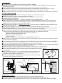
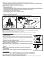
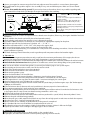
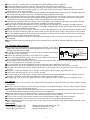
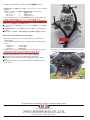
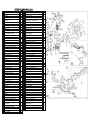
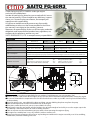
SAITO FG-60R3
4-Stroke Gasoline radial Engine Operating instructions
Thanks for buying SAITO FG-60R3 4-stroke gas-engine
exclusively for model planes.
In order to avoid misuse, please be sure to read well this instruction manual carefully. If there should be any deficiency, inconvenience, etc. Concerning the manufacture, our company will
repair them with responsibility.
Any failure or trouble caused by unnecessary disassembly,
modification, or other uses than those provided in the instruction manual is not subject to the warranty, however.
Moreover, all responsibilities for the use of the engine, and other
obligations and responsibilities based on laws, regulations, etc.
are borne by the purchaser and the user, and
SAITO SEISAKUSHO CO., LTD. is exempt from any responsibilities.
Specifications
Bore
Stroke
32.0mm x 3
25.0mm x 3
Weight (Approx.)
Body: 1,800g / Mufflers: 90g / Ignition system: 195g
Practical speed
Approx. 1,500-7,000rpm
Propeller
D21 x P10
D23 x P8
Disp.
Max on GND
Approx. 6,000-7,000rpm
Static thrust
Approx. 7kgf (Depend on prop)
Fuel
Regular gasoline:Oil=20:1 (Volume ratio)
Fuel consumption
Approx. 30cc/min (At full throttle 6,500rpm)
*Fuel flow varies depends upon prop load. More fuel flow with larger load and less fuel flow with smaller load.
Battery for ignition system
Voltage: 6-9V higher than 1,000mA is recommended
Standard accessories
Limit gauge (0.1t) for tappet adjustment
Plug wrench Spark plug [SP-2](Attached to the engine)
Muffler set (3 Flexible mufflers & Bracket)
Outside dimensions
Applications
60.32cc
1pc
1pc
3pcs
1set
2st Gas-engine 50cc class
Spanner for tappet adjusting lock nut
Hexagonal wrench 1.5mm
Ignition system(w/ sensor)
Stand off mount 39.5mm
1pc 1pc
1set
4pcs
167.5
39.5
Stand-off mount
66
82
M10×1
Φ220
5
5.
Φ
4-
24.6
207
77
51
44.6
Fig.1
NOTE&CAUTION
●Please note that we take no responsibility for any accidents, health damages, etc. using engine / fuel.
●If there s anyone stand in front of the engine, be sure to have them move behind the plane before starting the engine.
●Be sure not to breathe the evaporative emission of fuel and exhaust smoke as possible since they have harmful effects
on human body.
●Once the engine starts, move behind the plane and keep your arm holding the plane away from the prop.
●Make needle adjustment or other control from rear of the engine.
●If the plane cannot be fixed, ask your assistant to hold it for safety.
●During early stage of using engine, take the height in the air high enough to land safely in case the engine stop in the
air suddenly. It will reduce the risk of crash or landing accident.
●Take an extreme care for not bothering or injure others when operating the engine or flying.
●An engine for a model plane is not a toy. Handle it with an extreme care.
●Please note that our guarantee will not cover any breakage or trouble on the engine caused by user s disassembling,
modification, incorrect handling, and so on.
-1-
1. Propeller
●The Standard prop is Mejzlik D22 xP10 which brings approx. 6,400rpm
●Depending on the airframe, please adopt the adequate size in the range of 5,800 7,000rpm from reliable products
generally on the market.
●Since an imbalanced prop is vibratory and dangerous, please maintain balance with a balancer.
●A cracked prop should never be used. Make sure to check any time and replace it with a new one if it s cracked.
●Never use too low load prop as it leads large vibration and may result in engine failure or accident.
●Tighten up the prop nut after every flight. Especially a wooden prop tends to compressed so take care of its looseness.
2. Fuel, tank, piping
●Since gasoline is dangerous material, be careful of its storage, use, and transport enough.
●Unleaded high-octane gasoline is not required for SAITO engine.
●The fuel is mixture of commercial regular gasoline and reliable oil for 2-stroke engines.
●[Example of oil recommendation]
・Klotz KL-200 Original Techniplate
・Morgans Cool Power 'Blue' Synthetic Lubricant
etc.
●Lubrication for piston, connecting rod, bearing or cam gear is a blow-by lubrication in which the oil in the fuel goes
into the crankcase from the clearance between the cylinder and piston. Therefore the engine life is affected by the
property of the fuel oil. Please use the oil of reliable quality.
●Please be sure to use the mixture gasoline : oil =15 20 : 1 by volume ratio. (Ex. 1000ml of gasoline should be mixed
with more than 50ml of oil ).
●Any damage caused by the fuel used, in which the oil ratio is lower than 20:1 ratio, is not warranted.
●Please use pure gasoline as long as possible. In some areas in the world, standard gasoline contains specific amount
of ethanol. Such fuel may cause not only power loss but also corrosion inside the crankcase.
●If you can t get pure gasoline for the engine, please make sure to follow the procedure below after the last operation
of the day; to remove the blow-by gas from the crankcase and prevent the engine from corrosion.
1)Stop the engine by fuel cut to burn out the fuel in the carburetor.
2)Remove the remaining fuel from the tank.
3)Turn off the switch of the Ignition.
4)Open the throttle.
5)Apply an electric starter to the prop to run without fire for about 10 sec.
●Make sure to use gasoline-proof products for the tank, lid rubber, piping, and tubing. Some of the products for glow
fuel can t be used for gasoline.
●Use the gasoline proof tank which has adequate capacity (Approx. Fuel consumption x Flight duration + 100 200cc).
●The carburetor has a pump but its pumping pressure is not so strong. Place the tank as close to the carb as possible.
●Set the tank in order to make the fuel level slightly lower than the center of the carb.
●Since commercial gasoline contains many impurities, please be sure to use a reliable filter for the admission port of the
gasoline-proof fuel pump (Fig.2) and in the fuel tank as well (Fig.3).
●Without using filters, proper performance of the carburetor is not delivered, resulting in failures.
●Provide Fuel feeding pipe , Carb feeding pipe , and Air inhalation pipe separately (Fig.3).
Gasoline-proof tube
●When provide Air inhalation pipe as Fig.4, arrange the tube above the fuel level to Gasoline-proof
(Option)
Pump
avoid overflow.
●Please check carefully if there's any crack on the piping, tubing, connection, and
tank.(If there s any leakages, not only the performance of the engine decreases
dramatically but also there is danger of fire.)
Filter with weight
(Option)
●All of the connection parts should be bound by thin Nylon strap or wire to avoid
fuel leakage or air induction to the fuel line.
Fig.2
Stand-off mount
Air inhalation
pipe
Rubber cap for
gasoline-resistant
Above
Fuel level
Fuel tank
Fuel feeding pipe
Air inhalation pipe
Fuel level
To Carb nipple
Cut out
Fig.3
Gasoline-proof tube
To Outside of
the plane
Filter with weight
Close as possible
Center of fuel tank
Fig.4
3. Ignition system
●The ignition system develops extremely high voltage. Do not touch it during operation.
●Use a plastic clip to hold the connectors and spiral tube to protect each wire of the ignition system.
●Isolate the ignition system completely from the receiver, servos, and batteries to avoid a radio-interference trouble.
-2-
●Each switch (for Ignition and for Receiver) should be isolated and set far from each other.
●A gas-engine generates noise which has an adverse effect on RC equipment. Carry out a noise check each time while
the engine is running before flight. As a simple method, after starting engine you can check operating it about 50m
away from the plane. If there is no malfunction, it is safe.
●Charge the battery for the ignition system and RC device fully.
●The function of each cord;
(1) Plug cord (meshed high tension cord)
As Fig.6 shows there are three cords for three cylinders. Make sure to attach each number indicated on the main unit
to each cylinder (Refer to Fig.5 regarding cylinder number). When you put on the plug cap, insert deep into the plug to
avoid coming off during flight. And then pull the plug cap to confirm that it won t come off.
(2) Sensor cord (Gray cord with exclusive connector)
Connect with the cord from the sensor attached to the engine.
(3) Battery cord (black/red cord)
Please use the fully charged battery that has adequate spec. (6-9V, more than 1000mA is recommended.). Between the
battery and main unit, make sure to set a heavy duty switch whose capacity is higher than 3A.
(4)Tachometer cord (black/red/white cord)
Connect the digital tachometer (Option). Otherwise the connector is normally vacant.
er
rd
o
ing
Fir
Firing order
#1-#3-#2
Pro
Plug cap
pd
ire
(1)Plug cord
Main unit
cti
on
(2)Sensor cord
Switch (not included)
Capacity: more than 3A
#1
(3)Battery cord
(4)Tachometer cord
#3
#2
Recommended battery
5cell-NiMH or 2cell-LiPo
Voltage:6-9V
Capacity: 1,000mA
Sensor
Fig.5
From the Pilot s view
Fig.6
4. Spark plug
●UNEF1/4-32mm spark plug (SP-2) is the standard equipment.
●Attach the plug cap from the ignition system to each cap and insert the clip into the groove on the plug.
●Set the numbers of flights by yourself to replace the spark plug.
●Replace the plug to a new one when you flighted as many as above. (A spark plug is consumable.)
5. Engine Installation
●As the carburetor comes out from back of the firewall, cut out the firewall as adequate
size referring to Fig.3.
●Sometimes fuel get flown back from carburetor and may spatter inside the firewall. For
that case, make sure to cover the batteries, RC equipment and all the foam members with
gasoline-proof material.
●Make the firewall robust enough to endure vibration and torque.
●It is preferable to apply some adhesives (such as screw lock) on the tip of each cap screw
to avoid looseness when you install the engine.
●Take special care for cooling engine as insufficient cooling causes engine trouble such as
overheat, percolation, or muffler looseness.
●To ensure cool wind passes through the engine, the cowling should be devised. Building
some baffles inside the cowling is highly recommended for efficient cooling.(Fig.7)
●Make the air flow outlet area about 3-times larger than the inlet area.
●The mufflers should be securely inserted deeply into the adopter and tightened up using
spanners.
●Make sure to fix the outlet of the flexible mufflers outside of the cowling using the
attached bracket.
●To dispose of dirty oil from the breather, attach the gasoline proof tube to the breather
nipple and fix the other side of the tube on outside of the cowling. (Fig.8)
Baffle
Cool air
Cowling
Fig.7
Muffler outlet
Exhaust
Aluminum pipe
Fig.8
From
Breather nipple
6. Carburetor
●As to both needles, turn to CW, the fuel will become leaner and the rotation speed will increase.
Turn in CCW, the fuel will become richer and the rotation speed will decrease.
Main needle: To adjust the speed at the time of full open of the throttle.
Slow needle: To adjust the speed from the idling to the middle speed.
●Both needles are interfered slightly from each other so confirm the balance of peak and response after adjustment.
-3-
●Since a gas-engine has narrow range of air-fuel ratio, adjustment of the needles is severer than a glow-engine.
●The carburetor for the gasoline engine is the assembly of very strict and delicate parts. Make sure to use filtered
gasoline.
●Do not disassemble the carb by yourself. If you need to clean up the carb or there's any troubles regarding carb,
please consult the shop which you bought the engine from before disassembling.
Fig.9
Main Needle
Slow(Idle) Needle
(Adjust with ⊖screw driver)
CW→Lean
CCW→Rich
CW→Lean
CCW→Rich
CCW→Rich
CW→Lean
Slow
Throttle lever
High
Standard values for the needles
For Main needle:
1+1/6 1+1/2 turns open from full close
For Slow needle:
Approx. 6 7 turns open from full close
(Then throttle should be fully closed)
Actually the best condition of the needles
varies depending on the prop, temperature,
humidity and so on.
Please adjust seeing the engine performance
during flight.
7. Preparation for engine start
●Mount the engine on a robust and parallelized test bench or on the plane. (Either way, the engine should be fixed and
immobile.)
●Check whether the throttle can be fully closed and opened certainly.
●Check whether each code of the ignition system is connected certainly.
●Use about 1000cc tank for the test bench, or a tank which has appropriate capacity for the plane.
●Fill up the tank with the fuel mixture of gasoline : oil = 15 20 : 1 .
●Attach a well balanced D21 x P10 D23 x P8 prop to the engine shaft.
●To start with an electric starter, attach a spinner to the end of the shaft.
●To see the peak condition clearly, use a tachometer. It will prevent over-throttling or overheat. You can also use the
digital tachometer (Option).
●To check discharge from the breather, attach a gasoline-proof transparent tube to the breather nipple.
8. Break-in
●As Break-in is an important procedure not only to pull out the maximum performance of the engine, but also to
prevent the engine from overheat in the early stage of operation, it must be cautiously done.
●The purpose of break-in is initial lubrication and adjusting of the mobile parts under the condition of rich fuel mixture.
●Never make the fuel mixture lean during Break-in. It could cause seizure even during idling or low speed running.
---------------------------------------------------------------------------------------------------------------------●Be sure to turn off the switch of the ignition system until just before trying to start up the engine.
●After turning on the transmitter switch, turn on the receiver switch.
●Check if the throttle and other servos move properly.
●Open the main needle about 2 turns from full close.
●Power on the ignition system.
●Open the throttle about 1/4 from full close.
●Starting with excessively opened throttle is dangerous since the plane jumps forward.
●Apply the electric starter to the prop and activate for about 5-10 seconds to start the engine.
●If the engine doesn t start up, open the main needle 1 turn more and apply the starter again.
●Once the engine starts run it for about 10 sec in low speed.
●Open the throttle fully and open the main needle until the speed drops just before engine stops. (Ref. Under approx
4,000rpm at full throttle.)
●If the fuel mixture doesn t become rich and speed doesn t decrease, open the slow needle too.
●Then continue running for 2 tanks under the same condition.
●During this initial operation, contact of each part inside the engine will be matched. So make the fuel mixture as rich
as the engine doesn t stop. Do not care about running smoothness at this step.
●Refill the tank and start up the engine again.
●Open the throttle fully and turn the main needle to achieve peak and less speed (richer) alternately about 5 times.
●Maintain the peak condition long gradually.
●When the peak gets stable, operate the throttle to vary from slow to high speed several times to check the response.
●After that run it for 2-3 minutes keeping high speed.
●When it comes to run smoothly at peak, break-in on the ground is completed.
●Fly it for about 20 times in rich condition to complete break-in in the air.
●After break-in, please run the engine in slightly rich condition as long as it doesn t affect to the flight.
●Tighten up the whole screws and adjust the tappet gap as discussed later.
9. Needle adjustment
●Before adjust the needles please set both needles as the standard values.
●In principle, the carburetor should first achieve peak by adjusting the main needle.
-4-
●Unless the peak is certainly achieved, idle adjustment will be difficult and not stabilized.
●Start up the engine and run for 1 minute in rich condition. Then fully open the throttle.
●By turning the main needle CW, observing tachometer and exhaust sound, achieve peak carefully.
●Operate the throttle to low until the engine runs stably with an idle speed around 1,500rpm by adjusting the slow
needle with a ⊖screw driver carefully.
●Once idle speed is set, open the throttle to full gradually. If the speed becomes slow or goes up suddenly, adjust the
slow needle carefully until the speed rises linearly from idling to peak by fine-tuning.
●After that perform the process from idling to peak quickly. If the speed rises non-linearly, fine tune the main needle.
●If the speed around slow-mid range gets cough or hesitating, fine tune the slow needle and check the response as
well. Repeat this fine-tuning and response check carefully until the response improves.
●Carb adjustment is affected by many factors such as prop, flight style, humidity, temperature, atmosphere, oil, plug,
fuel, and so on. Please keep trying to find the best condition to match your plane.
●The best richness of the air-fuel mixture at slow speed depends on the flight style. Generally, Scale flight requires
stability in low speed so slightly lean condition is preferable. Acrobatic flight requires quick response from low through
high, so slightly rich condition is preferable.
●Tip for adjustment of the slow needle is to make it as lean as the engine doesn t get stole when open the throttle quickly.
●To keep the engine life longer, adjust the main needle as rich as possible in the range it doesn t affect to the running.
●Since over throttling of the main needle leads to knocking or overheat and has an adverse effect on the connecting
rod and cam gear, adjust a little richer than peak.
●Once you notice abnormal vibration or sound during throttling the main needle, just return to open the needle
immediately.
●Where the plane achieves peak completely at the attitude of ascent should be a proper peak of the engine during
flight.
10. Tappet adjustment
●After completing ground break-in or operating the engine for 1 hour, adjust
Tappet adjustment
tappet gaps (valve clearances) by following procedure to compensate initial
Close to "0" with no limit
wearing, while the engine is cold.
Limit gauge
●#1 cylinder should be adjusted first, next #3, finally #2 cylinder should follow
(0.1mm)
in order by the same procedure.
Must not be inserted
●Remove the spark plug and rocker covers from the #1 cylinder.
(over gap)
●If the attached gauge (limit gauge, t=0.1mm) comes to be inserted, gap has Fig.10
been enlarged beyond the allowable limit.
●Turn the prop slowly forward by hand until the rocker arm of intake stops. Further turn the prop to bring the piston to
the TDC (Top Dead Center) of compression stroke.
●Use the attached wrench and hexagonal wrench to adjust the gaps indefinitely close to zero.
●After adjustment, put on the spark plug and turn the prop forward to check if the compression is enough.
●If the gap is lower than 0, the valve is opened all the time so the compression is not generated (then, loosen the screw
to reset).
●If the gap is correct and compression is enough, securely tighten (but not excessively) the lock nut.
●Do the same adjustment for the #3 - #2 cylinders in order.
●For SAITO engines, the tappet gap is enlarged during operation due to thermal expansion of the cylinder (made of
aluminum). Therefore set the gap indefinitely close to zero when the engine is cold.
●As tappet gap is one of the most important factors in the maintenance of 4-stroke engines, occasionally check it.
11. Other
●During operation, the screws all over the engine can be loosen by heat expansion of metal. So please tighten up them
occasionally.
●Just after start up the engine, perform warm up running in rich condition for about 1 minute, and just before stop run
it at idling for 1 minute to cool down as well.
●When stop the engine after the final flight of the day, be sure to stop by cutting fuel to remove fuel from the carburetor. And remove the fuel from the tank and reserve it with special care.
●When the exhaust valve gets dull by carbon or sludge especially in cold atmosphere, remove the rocker cover and
apply some anti-rust spray to the exhaust valve to help the valve to move smoothly.
●Never use anti-rust spray that contains organic solvent which degrades rubber seals inside the engine.
●Sometimes the oil oozes from each joint or commissure however it s no problem on performance.
●Notes for purchasing parts: Please give orders to the shop you purchased from with Engine model , Part No. or part
name , and Quantity .
Optional parts
・Filter with weight [G36-154]
・Rubber tube for gasoline(1m) [G36-155]
・Spark plug SP-2 [G60R3-120]
・Aluminum spinner nut [57T-30]
・Tappet adjusting kit [30-161]
・Digital tachometer [G17-167]
-5-
フレキシブルエキゾーストパイプの接続について
#1
①写真を参考に、下の組み合わせで各シリンダーとエキゾーストパイプを接
続します。
接続ナットは、各パイプが回転する程度に仮止めにしておきます。
#1シリンダー
→
最長のパイプ
#2シリンダー
→
最短のパイプ
#3シリンダー
→
中サイズのパイプ
②ブラケットとM3ボルト、
ナットで、排気端を絞り込むようにまとめます。仮
止めに、一部紐で束ねておくとブラケットでまとめ易くなります。
③排気端よりもシリンダ側も、
もう一つのブラケットで同様にまとめて固定し
ます。
④各シリンダーの接続ナットを本締めします。
●エキゾーストパイプと防火壁、インテークパイプが接触しないように固定
して下さい。
●下の写真を参考に、パイプの曲げがきつくなり過ぎないように取り付け
て下さい。
●曲がりのきつい箇所は、排気熱の高温により破損する可能性があります。
4
4
#3
#2
4
How to Fix the flexible exhaust pipes
ブラケット
Bracket
①Referring to the picture, insert the exhaust pipes to the cylinders as
following pairs.
At this step, leave the bushing nuts temporary fixed to allow the pipes
to turn.
#1Cylinder →
Longest pipe
#2Cylinder →
Shortest pipe
#3Cylinder →
Middle pipe
②Fix the ends of the pipes with the bracket , M3 screw and nut. Temporary binding the pipes with a band will help to fix the bracket.
③Fix upper part of the pipes with another set of the bracket.
④Finally tighten the bushing nuts to fix the pipes completely.
●Fix the pipes not to touch the firewall and the intake pipes.
●Referring to the picture below, attach the pipes without too much
bent.
●Too much bent causes not only power loss but also break due to heat
from exhaust.
3
2
※写真はFG-84R3ですが、方法は同じです。
※Though the above sample picture is FG-84R3, the procedure
is just the same.
All specifications and models are subject to change without notice.
http://www.saito-mfg.com
SAITO SEISAKUSHO, CO., LTD.
22-7, 3-chome, Tokagi, Ichikawa-shi, Chiba prefecture 272-0024, Japan
Phone: 047-378-4156 FAX: 047-378-4155
-6-
SAITO FG-60R3 Parts List
No.
Item
Qty
01 Cylinder
3
06 Piston
3
07 Piston pin
3
08 Piston pin retainer
6
09 Piston ring
3
No.
46
47
Item
Valve set (In & Ex)
46-1,-2
Valve spring & Keeper & Retainer
47-1,-2,48
48 Valve retainer (Cotter)
Qty
3set
6ea.
6
10 Master rod
1
49 Rocker arm cover
6
11 Linked conrod
2
69 Intake pipe
3
12
14
Conrod linkpin & E-ring
12-1,-2
Cylinder screw set
14-1,-2
1set
3set
15 Crankcase
1
17 Rear cover A (Intake manifold)
1
18 Rear cover B
1
19 Breather nipple
1
20 Front ball bearing
1
21 Main ball bearing
1
23 Crankshaft
1
27
28
31
32
Taper collet & Drive flange
27-1,-2
Prop washer & Nut
28-1,-2,-3
Crankcase screw set
31-1,-2,-3,-4,-5,-6
Engine gasket set
32-1,-2,-3,-4,-5,-6
1ea.
1ea.
78
83-1 31-6,82-1-1,-1-2,-1-3,-1-4,-1-7,-1-8,-1-13,
3
36 Cam gear shaft
3
37 Steel washer set
3set
1set
1set
-1-14,-1-15,-1-27,-1-28,-1-29,-1-31,91-1
85
87
88B
Main needle
85,90-1
Throttle barrel assembly
82-1-5,-1-9,-1-16,88B,89,90-1
Throttle lever
88B,90-1
89 Slow needle
1
1set
1
1
Carburetor screw & spring set
90 82-1-7,-1-8,-1-13,-1-16,-1-17,-1-26,-1-28,
1set
90-1,31-6
1set
35 Cam gear
1set
Carburetor body assembly
91
3
78-1,-2,-3,-5,-6
82-1 Carburetor complete
1set
33 Cam gear housing
Muffler complete
95
Carburetor gasket set
82-1-9,-1-14,-1-18,-1-20,-1-22,-1-31,90-1
Engine mount set
95-1,-2,-3,-4
110 Anti loosening nut
1set
1set
1
120 Spark plug
3
121 Master rod retainer (Crank pin plug)
1
38 Tappet
6
131 Throttle valve extension adapter / set screw
1
39 Pushrod
6
152 Screw-pin
1
40
Pushrod cover & Rubber seal
40-1,-2,-3
41 Rocker arm
42
Rocker arm screw & Nut
42-1,42-2
43 Rocker arm pin
6ea.
6
6ea.
6
153
Electronic ignition system
153-1,-2,-3,-4
1set
Pump assembly
160 82-1-17,-1-18,-1-19,-1-20,-1-21,-1-22,-1-23,
-1-24,-1-25,-1-26
1set