1
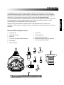
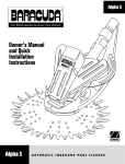
H0343700 Rev -
Owner’s Manual
Guide du propriétaire
Manual de Usuario
Important Information
English
WARNING
RISK OF SUCTION ENTRAPMENT HAZARD, WHICH, IF NOT AVOIDED CAN RESULT IN
SERIOUS INJURY OR DEATH. Ensure that your vacuum suction fittings installed in your pool for
connection of your suction-side pool cleaner are certified as being compliant with applicable safety
standards such as IAPMO SPS 4. Do not block the suction fittings with any part or your body. Do not
expose your hair, loose clothing, jewelry, etc. to any suction outlet fittings in the pool/spa.
Notice for Vinyl Liner Pools: Before installing your pool cleaner, examine the interior of your pool
carefully. If the vinyl liner is brittle or has stones, wrinkles, roots or metal corrosion in contact with the
underside of the liner, or has damage to the base material or supporting walls, do not install the cleaner
before having a qualified professional perform the necessary repairs or liner replacement. Zodiac Pool
Systems, Inc. (Zodiac) will not be responsible for liner damage caused by a cleaner which is
in disrepair, pattern removal from a vinyl liner, or a cleaner used in a pool having an aged or
deteriorated liner. Please see Limited Warranty.
• To help prevent suction entrapment accidents, wall vacuum fittings should have a safety vac lock
installed. Contact your builder or retail pool professional for details.
• Clean the skimmer basket, pump basket and pool filter before installing the cleaner and on a
regular basis thereafter.
• Always disconnect the cleaner from the pool wall or skimmer before cleaning or backwashing the
pool filter. After cleaning or backwashing, let the filtration system run for at least five (5) minutes
before re-connecting the cleaner.
• Remove the cleaner from the pool before chemical or shock treatments. Wait a minimum
of four (4) hours after super chlorination before re-installing the cleaner.
To ensure prompt warranty service, should it be required, please:
• Complete and return the Zodiac® Warranty Card.
• Record your purchase information.
• Attach a copy of your purchase receipt to this document.
Date of Purchase: ___________ Purchased From: __________________________________
Serial Number (located under the hood) ___________________________________
If service is required, simply present your manual with the attached receipt at any Zodiac waranty center.
For customer service or support:
Zodiac Pool Systems, Inc.
2620 Commerce Way
Vista, CA 92081-8438
1-800-822-7933
2
Introduction
Congratulations on the purchase of your new Baracuda® MX™ 8 automatic pool cleaner. Built with
proven Baracuda technology, the Baracuda MX 8 is designed and manufactured for easy installation,
and years of carefree operation. Before installing the cleaner, please take a few moments to become
familiar with its components and to review the items listed under Important Information.
Always insist on genuine Zodiac® replacement parts. Non-Zodiac parts are not made to our
specifications. They may have an adverse effect on the operation of your Baracuda MX 8 or may even
damage it.
English
Like most mechanical devices, the Baracuda MX 8 requires periodic adjustments, routine maintenance,
and the replacement of certain hardworking parts. Be sure to have the Baracuda MX 8 checked
occasionally by your local Baracuda dealer or service center.
Baracuda MX 8 Complete Cleaner
1. Cleaner Body
7. Hose Float
2. Flowkeeper™ Valve
8. 45 Degree Elbow
3. Valve Cuff
9. Twist-Lock Hose Section
4. Twist-Lock 45 Degree Elbow Extended
10. Zodiac Leaf Catcher (W26705) (Optional
device for high debris areas)
5. Flow Gauge
6. Quick Connector
2
4
3
10
6
7
5
6 5 4 3 2 1 0
8
0 1 2 3 4 5 6
1
9
3
Installation
Prepare the Pool
1. Manually vacuum the pool, and make sure the pool filter and pump basket are clean.
2. Close the pool main drain line.
English
3. Aim the return line fittings down.
Assemble the Hose
The hose uses easy twist-lock connectors. Push and twist the connector on each hose section until they
lock into position with clicking sound. The hose cuffs have three (3) connection positions. Any of the
three (3) positions are sufficient for an air-tight seal.
1. Connect enough hose to reach the farthest point of the pool and then add one more section.
2. Position the hose float on the first hose section, about nine (9) inches from the cleaner head.
3. Twist lock the quick connector on the end of the hose where the head will be connected.
1 Hose
Section
Skimmer or
Dedicated Suction
Cleaner Line
Hose Float 9”
from Cleaner Head
Skimmer or
Dedicated Suction
Cleaner Line
Hose Float 9”
from Cleaner Head
1 Hose
Section
4
Connect the Hose
WARNING
Turn on the filtration system and fill the hose with water by placing
the end in front of a return inlet until it is flooded. Turn off the
pump.
To connect to a dedicated suction line:
English
RISK OF SUCTION ENTRAPMENT HAZARD, WHICH, IF NOT AVOIDED CAN RESULT IN SERIOUS
INJURY OR DEATH. Ensure that your vacuum suction fittings installed in your pool for connection of
your suction-side pool cleaner are certified as being compliant with applicable safety standards such
as IAPMO SPS 4. Do not block the suction fittings with any part or your body. Do not expose your hair,
loose clothing, jewelry, etc. to any suction outlet fittings or hose ends in the pool/spa.
Hose
1. Twist lock the male end of the hose into the large end of the
45° elbow.
Elbow with
Twist-lock
2. Connect the elbow to the safety vac wall fitting.
Dedicated Cleaner Line
with Safety Vac Lock
(not included with cleaner)
3. Angle the elbow upward towards the water surface.
To connect to a skimmer:
The FlowKeeper™ valve must always be used in single
skimmer installations. The valve regulates flow to ensure the
pool pump and cleaner run properly. It is pre-set at the factory
to optimize the performance of the cleaner, but offers three (3)
settings to adjust the flow.
FlowKeeper
Adjustment
The lower the setting number, the lower the flow. To adjust, pull
the handle and move setting up or down. The red tab can be used
to open the valve and stop the cleaner.
If the pool has more than one skimmer, connect the hose to
the one closest to the pump.
The parts used to connect the hose, and the sequence in which
they are installed depends on the type of skimmer.
1. Remove the skimmer basket.
2. Insert the valve cuff and connect the FlowKeeper with the
arrow pointing down towards the skimmer pipe.
3. Choose the fitting combination that best suits the skimmer to
complete the connection.
45 Elbow
FlowKeeper
Valve
Valve Cuff
5
Test and Adjust for Proper Flow
Disconnect the cleaner head and attach the Flow Gauge. Keep the Flow Gauge under water and have
someone turn on the pump.
English
Verify that the red indicator in the gauge (viewed from the side) is at the Number 3 setting.
6 5 4 3 2 1 0
0 1 2 3 4 5 6
If necessary, use the valves in the pool equipment area to adjust the flow.
•
For skimmer connections on pools with one skimmer, flow is automatically regulated by the
FlowKeeper™ Valve. The red indicator should be at the proper setting.
•
For skimmer connections on pools with more than one skimmer, leave the valve for the
skimmer connected to the hose open and slowly close the other until the proper setting is reached.
•
For dedicated suction line connections, leave the vacuum line open to the cleaner and slowly
close the skimmer line until the flow is at the proper setting.
If flow is in the low range (0-2):
• Check and clean the pool filter and baskets if necessary.
• Verify that valves controlling the suction lines are in the correct position.
If flow is in the high range (4-6):
• Verify that valves controlling the suction lines are in the correct position.
• Lower the flow setting on the FlowKeeper Valve.
6
Connect the Cleaner
WARNING
To avoid serious injury, make sure to turn off the suction pump that is responsible for the pool cleaner
operation. Do not expose your hair, loose clothing, jewelry, etc. to the open end of the hose.
1. Submerge the cleaner and flood it with
water.
English
Turn off the pump. Keeping the hose
underwater, remove the Flow Gauge.
2. When bubbles stop coming from the
cleaner, connect the hose by pushing the
Quick Connector onto the cleaner.
3. Allow the cleaner to sink to the bottom of
the pool.
4. Turn on the pool pump and begin
cleaning.
7
Operation and Routine Maintenance
English
The Baracuda® MX™ 8 cycles on/off with the pool filtration pump, vacuuming and cleaning all surfaces
randomly throughout the pool. The climbing ability of the cleaner is dependent on the pool’s shape and
available water flow. If Baracuda MX 8 is not climbing your walls, ensure the flow is correct by using the
Flow Gauge. Also, ensure the pools surface is not covered in algae as this slippery surface will affect
the cleaner’s traction.
During each coverage pattern cycle, the cleaner travels both forward and backwards, and pivots to the
right and left. The power scrubbers underneath the cleaner create down force for climbing and stability
as well as directing debris into the cleaner mouth.
Emptying the Pump Basket
For the Baracuda MX 8 to operate at optimum efficiency, empty the pump basket regularly. The more
debris in the pool, the more often the pump basket should be cleared. Zodiac® offers an in-line leaf
canister which will trap solid debris before it enters the pump basket. See your Zodiac dealer for details.
Backwashing the Pool Filter
Always disconnect the Baracuda MX 8 from the pool wall before cleaning or backwashing the pool filter.
After cleaning or backwashing, let the filtration system run for at least five (5) minutes to flush out the
suction lines before re-connecting the cleaner.
Adding Chemical to the Pool
Remove the cleaner from the pool for at least four (4) hours when adding chemicals.
Storage and Winterizing
Never store the Baracuda MX 8 in direct sunlight. When storing for the winter, drain out all the water
(freeze damage is not covered by the warranty). Remove all connectors and adapters from the
dedicated suction line or skimmer. When storing the cleaner, even for short times, do not coil the hose
as the hose may develop a memory which can affect cleaner performance. Disassemble the hoses and
layout flat.
8
Remove Debris from Engine
WARNING
To avoid serious injury, make sure that the cleaner is disconnected from the hose and the suction
pump used for the cleaner is turned off prior starting this operation.
English
1) Push the latch release button on the top of
the cleaner.
2) Rotate the top assembly back until it clicks
into an upward position.
3) Look into engine and remove debris that is
present.
Latch Release
Button
4) If needed, slowly push engine paddles
forward and/or backwards to move stuck
debris to an accessible position then remove
it. When moving the engine paddles, make
sure the cleaner tracks are allowed to move
freely as they will turn as the engine paddles
rotate.
5) Close engine top and ensure the latch clicks
in place.
9
Troubleshooting
English
If you experience a problem with your Baracuda® MX™ 8, please follow the troubleshooting steps below
to restore performance. If further assistance is required, contact Zodiac® Technical Support Department
at (800) 822-7933. Please have your serial number and date of purchase available when you call.
Problem
Solution
Cleaner does not move or moves slowly.
• Confirm that the main drain is closed.
• Use Flow Gauge to verify proper flow.
• Check for debris jammed in engine. Backwash filter and
empty pump basket.
• Check for air in system. If water level in pump basket
drops or you see excessive air bubbles in the pump
basket or coming from the return lines, there is air in the
system. Check hose connections, tighten all fittings at
pump and check o-ring at pump basket for wear.
Cleaner patterns, does not cover entire pool. • Use Flow Gauge to verify proper flow.
• Ensure return fittings are directed down. Add a return
diverter if necessary.
• Make sure hose is not kinked or coiled. Lay in sun to
straighten if necessary.
• Verify correct hose float positioning.
• Observe cleaner for more than five (5) minutes and
ensure that each drive track is periodically reversing
direction. If it is not, contact you dealer or service center
for help.
• Confirm proper hose length.
Cleaner gets stuck at steps.
• Observe cleaner for more than five (5) minutes and
ensure that each drive track is periodically reversing
direction. If it is not, contact you dealer or service center
for help.
• Ensure the swivel on top of the cleaner rotates freely.
• Use Flow Gauge to verify proper flow.
• Confirm proper hose length. Shorten if necessary.
Cleaner won’t climb walls.
• Using Flow Gauge as guide, increase flow to cleaner.
• Verify correct hose float positioning.
Cleaner climbs too much.
• Using Flow Gauge as guide, reduce flow to the second
setting.
• Verify correct hose float position.
10
Baracuda® MX™ 8 Parts Diagram
1
3
27
2
4
5
6
28
8
29
7
6
30
0 1 2 3 4 5 6
4
English
6 5 4 3 2 1 0
9
10
11
32
31
11
10
12
17
13
16
14
6
18
11
15
19
11
6
14
20
21
22
6
24
11
6
19
23
11
18
17
25
25
26
No.
Part #
1
2
3
4
5
6
7
8
9
10
11
12
13
14
R0526800
R0526900
R0525400
R0526500
R0526400
R0527100
R0525900
R0526300
R0526600
R0525100
R0527000
R0524900
R0525800
R0527200
15
16
R0525600
R0524800
Description
MX8 HOSE FLOAT
QUICK CONNECTOR (BLUE)
MX8 TOP COVER W/SWIVEL ASSEMBLY
MX8 ENGINE SEAL
MX8 ENGINE GUIDE
SCREW, M4x12mm, PHILLIPS #2 PAN HEAD
MX8 MIDDLE ENGINE HOUSING
MX8 COVER LATCH
MX8 BODY PANEL - RIGHT (B)
MX8 DRIVE SHAFT ASSEMBLY
BEARING, (WHEEL & ENGINE)
MX8 ENGINE ASSEMBLY
MX8 LOWER ENGINE HOUSING
SCREW, THREAD FORMING,
#6-18 7/8in TYPE A, PHILLIPS #2 PAN HEAD
MX8 BODY PANEL - REAR (D)
MX8 DIRECTION CONTROL DEVICE - SIDE B
Qty.
1
1
1
2
1
16
1
1
1
2
10
1
1
2
1
1
No.
17
18
19
20
21
22
23
24
25
26
27
28
29
30
31
32
Part #
R0526100
R0526200
R0526000
R0524700
R0526700
R0525200
R0525700
R0525500
R0525000
R0525300
R0527700
R0527400
R0527500
R0527600
R0532400
R0532500
Description
MX8 TRACK
MX8 WHEEL PIN
MX8 WHEEL
MX8 DIRECTION CONTROL DEVICE - SIDE A
MX8 BODY PANEL - LEFT (A)
MX8 CHASSIS ASSEMBLY
MX8 LOWER BODY HOUSING
MX8 BODY PANEL - FRONT (C)
MX8 SCRUBBER ASSEMBLY
MX8 INLET ASSEMBLY
TWIST LOCK HOSE - 1 METER, BLUE/GRAY
FLOWKEEPERTM VALVE
FLOW GAUGE
IN-GROUND VALVE CUFF
TWIST-LOCK 45 DEG ELBOW, EXTENDED
45 DEG ELBOW
Qty.
2
4
4
1
1
1
1
1
2
1
12
1
1
1
1
1
11