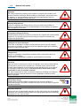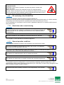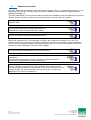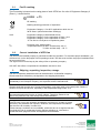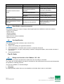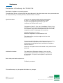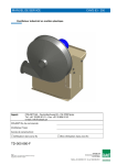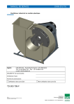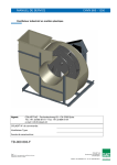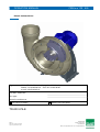
1
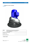
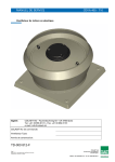
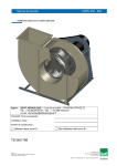
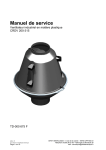
OPERATION MANUAL CMVeco 125 - 400 Plastic industrial fan Agent: COLASIT AG – Faulenbachweg 63 – CH-3700 Spiez Phone: +41 33 655 61 61 – Fax: +41 33 654 81 61 e-mail: [email protected] COLASIT Order No.: Fan type: Year of manufacture: For use in Ex zones Not for use in Ex zones TD-000 674-E COLASIT AG Page 1 Edition 2011 / Subject to alteration Copyright by COLASIT AG Spiez Plastic construction CH-3700 Spiez Phone +41 (0)33 655 61 61 Fax +41 (0)33 654 81 61 1.8 General risk matrix Operation The safety regulations prevailing at the operator’s location are mandatory and must be observed at all times. Before making an intervention, the process must be stopped, i.e. all mechanical movement must be stopped and it must be ensured that no automatic motion can occur. Missing safety devices If the fan is equipped with safety devices, they may neither be modified nor removed. Further safety devices of suitable design must be fitted by the operator and are subject to his control. Disregard of safety precautions Please implement all safety measures so that the fan, together with its associated equipment, can operate properly and any danger to persons, materials and products can be excluded. Putting the fan out of operation In the case of damage to or failure of safety devices, the fan must be stopped and put out of operation. It may only be put into operation again when the safety devices are fully functional again. Overpressure If the fan is operated in overpressure conditions with normal seals, there is a danger of gas escaping. For operation in overpressure conditions, special seals must be fitted. Electricity When any work is carried out on the fan, the electric motor must be deenergised and secured to prevent it from switching on. The main power switch must be secured against operation by third parties using a lockable device (e.g. padlock) by the persons working on the fan. Full disconnection of the motor is only permissible in case of complete removal! The safety regulations for work on electrical equipment prevailing at the place of operation must be observed at all times and be available for reference at the place of operation. Electrostatic charge Media flowing through the plastic components may cause the buildup of electrostatic charge. These are harmless to persons who do not react to electrical impulses in the body Unsuitable materials Through the use of inappropriate materials, the fan and/or parts may be damaged or become non-functional. Please always use original spare parts and contact the manufacturer in any case of doubt. COLASIT AG Page 6 Edition 2011 / Subject to alteration Copyright by COLASIT AG Spiez Plastic construction CH-3700 Spiez Phone +41 (0)33 655 61 61 Fax +41 (0)33 654 81 61 Dangerous media Depending on the mode of operation, fan parts may come in contact with dangerous media. Work on the fan or carrying out maintenance work is not allowed during operation. Before carrying out any work, any dangerous media must be removed from the system and, when required, must be neutralized and secured in such a way that an inflow of dangerous media is prevented. 1.9 EC conformity of the COLASIT fan The fan was designed, built and tested to Directive 2006/42 EC. In addition to this EC Directive and EN standards which have the equivalent status of a Swiss standard, Swiss safety and accident-prevention regulations have also been taken into account. An EC Declaration of Conformity in terms of the EC guidelines 2006/42 EC on machines will be issued along with the fan. 1.10 Restrictions when commissioning We stipulate that putting into operation is prohibited as long as the fan, including all parts belonging to it or equipment connected to it, has not been installed and checked out and until the operating manual has been read completely before commissioning. We stipulate that the fan may only be put into operation when the safety inspector has given his approval. He is obliged to record this approval in a protocol. The disregard of these stipulations constitutes negligence. 1.11 General operation conditions The permissible operating conditions are indicated on the manufacturer‘s plate. The fan is not suitable for the transport of solids in the air flow. This operating mode will lead to the destruction of the fan. The ducts on the intake and delivery sides must always be open. A closed duct will lead to a rise in temperature which could cause the destruction of the fan. The minimum air speed through the fan is 3 meters per second. The maximum air speed may not exceed 30 meters per second through the fan. The standard motors are designed for normal operating conditions (ambient temperature +40°C, altitude below 1000 m above sea level, air pressure up to 1050 hPa). In case of any divergence from these conditions, please contact COLASIT. Compliance with these operating conditions is the responsibility of the operator. COLASIT AG Page 7 Edition 2011 / Subject to alteration Copyright by COLASIT AG Spiez Plastic construction CH-3700 Spiez Phone +41 (0)33 655 61 61 Fax +41 (0)33 654 81 61 2 Explosion protection COLASIT plastic fans are suitable for the conveyance of gases in Zone 1 or 2 (Equipment Category 1 or 2) depending on the model. COLASIT plastic fans are not suitable for the conveyance of gases in Zone 0 (Equipment Category 1). The zone classification of the conveyed medium and the site of installation must be made known by the fan operator so that COLASIT can take the necessary measures to prevent the risk of ignition. The explosion-proof COLASIT fans are not suitable for the conveyance of explosive dusts No modifications may be made to ATEX-certified fans. All work on the fan may only be carried out by ATEX-trained skilled personnel. Otherwise the ATEX Certificate will lose its validity. On ATEX certified fans, the external grounding terminal of the motor and fan must be connected to a potential equalization system. Motors with protection type "e" are standard for using in the explosion-proof design of our fans. The standard version of the motors used complies with temperature class T3 (maximum surface temperature 200ºC). As special-purpose design, motors with protection type "d" or motors with temperature class T4 (maximum surface temperature 135°C) are also available. The user must define a suitable temperature class for his application that does not reach the ignition temperature of his conveyed medium. Please also observe the specifications in the operating instructions of the motor manufacturer. The thermal motor protection must be connected in compliance with the manufacturer's specifications (operating instructions). If a frequency converter is fitted, we recommend using pressure-proof enclosed motors. In addition, a certified PTC resistor releasing device must be fitted. The following specifications must be included on the motor rating plate: min and max frequencies, min and max speeds, min and max torque or output, limit temperature PTC and PTC release time. COLASIT AG Page 8 Edition 2011 / Subject to alteration Copyright by COLASIT AG Spiez Plastic construction CH-3700 Spiez Phone +41 (0)33 655 61 61 Fax +41 (0)33 654 81 61 2.1 Fan Ex marking The Ex marking is located on the rating plate of each ATEX fan. On a fan of Equipment Category 2 (Zone 1), it looks like this II 2/3G c T3 CE-marking Marking denoting prevention of explosions II Equipment Category II, for all Ex applications which do not fall in Class I (mines and surface workings). 2/3G Equipment Category inside/outside the fan Equipment Category 2 is the equivalent of Zone 1 and Equipment Category 3 is the equivalent of Zone 2 “G“ fan fort he conveyance of expolosive gases c T3 Protection type „design safety“ Temperature class T3: Max. surface temp. 200 °C T4: Max. surface temp.. 135 °C 2.2 Correct installation of ATEX fan The fan must be installed properly to guarantee trouble-free operation. To document proper installation, you will find a form on the last pages of this operating manual. The fitter must confirm the proper installation item for item on this form. The signed form must be kept by the safety officer or operating company. COLASIT also offers a comprehensive installation service for fans. 3 Shipping, unpacking, inspection, storage The fan is completely assembled and can be delivered in a closed film wrapping. Please make sure the delivery corresponds to the shipping documents. Please examine the packaging for external damage and report any damage immediately to the transport company, the supervisor and the manufacturer. Please handle the fan with care. During transportation, only apply strain on the steel parts. Plastic is sensitive to impact and knocks, especially in the temperature range under +5°C. When the film is removed, the intake and pressure nozzles are open and unprotected against the intrusion of foreign objects. Therefore, please do not remove the protective film until shortly before final installation. Storage If the fans are not put into operation immediately, store them in a clean dry place where they are protected from impacts, vibrations, and temperature fluctuations and where the air humidity is under 90%. If these storage conditions are not available, switch the fans on at regular intervals to exclude the risk of condensate forming. Before switching on, unscrew the condensate drain plugs each time and replace them afterwards. COLASIT AG Page 9 Edition 2011 / Subject to alteration Copyright by COLASIT AG Spiez Plastic construction CH-3700 Spiez Phone +41 (0)33 655 61 61 Fax +41 (0)33 654 81 61 Store the fan in a dry, weather-protected place and cover with a tarpaulin to protect it from dust and soiling. If stored for over one year, test whether the fan bearings rotate freely before putting into operation. 4 Installation, configuration Before installation, check whether all the locking screws (including the motor screws) are tightened properly. Check the electrical connections if wired at the factory. Before installation, check that there are no foreign bodies in the coil or in the intake and pressure connections. The fan must be installed at a location provided and prepared by the customer and must be secured and connected in such a way that any possible vibration occurring can be absorbed by the vibration dampers supplied by COLASIT. If no ducting is foreseen on the intake side, the intake connection should be protected by a sturdy protective grating (10mm mesh) to be provided by the customer. Connection ducting on the pressure side must be routed to prevent the backflow of foreign bodies, rainwater or condensate into the fan. To ensure this, please use the COLASIT condensate drain nozzles. Due to the possibility of noise nuisance, we recommend that the fan should not be installed in the immediate vicinity of workplaces. 5 Commissioning, initial startup, test run The fan should only be put into operation after inspection and approval by the safety officer. 5.1 Inspection of the installation and settings Check list: Prior to commissioning and initial start-up, it must be guaranteed that the fan is installed vibration-free and mechanically secured, all components are cleaned both on the inside and the outside and are free from foreign bodies, all intake and pressure ducts connections are leak-proofed all rotating parts are protected against unintentional contact, the electrical connections are installed and their function tested, a lockable main control switch is available to which the fan is connected the EMERGENCY-STOP equipment is functionally tested, the safety inspector has made sure that safety equipment exists, the operating personnel is familiar with the operating manual, the safety inspector has given his approval fort he operation of the installation and that no external persons are present in the plant area If envisaged by procedural regulations provided by the operator, minutes have to be taken on the commissioning work, including the observance of the check list. COLASIT AG Page 10 Edition 2011 / Subject to alteration Copyright by COLASIT AG Spiez Plastic construction CH-3700 Spiez Phone +41 (0)33 655 61 61 Fax +41 (0)33 654 81 61 5.2 Drive The fan is driven by an electric motor which is connected to the impeller shaft either directly or via a V-belt. The motor electrical specifications are indicated on the motor’s rating plate or in the motor manufacturer’s data sheet. When speed is controlled by means of a frequency converter, the maximum speed is limited by COLASIT to the value indicated on the manufacturer’s rating plate. If the frequency converter is not supplied by COLASIT, the operator is responsible for compliance with the maximum speed limitation. In this case, COLASIT will not assume any liability for damage that may be attributed to exceeding the maximum speed. In the case of motor outputs over 3kW, we recommend the use of a soft starter or a star-delta connection. 5.3 Electrical installations, EMERCENCY STOP The electrical installations may only be carried out by an authorised electrician in accordance with the regulations prevailing at the site at which the fan is installed. To interrupt the power supply, an EMERGENCY STOP switch must be provided. It is advisable to mount this switch in the vicinity of the emergency exit. Please request confirmation from an in-house electrician that the electrical installations were carried out and tested in accordance with regulations, that all functions were tested (or simulated) and that the rotational direction is correct. Warning Do not turn power on or off without prior warning to persons in the area where the fan is operating. Switching operations must be co-ordinated with other functions in the working area of the fan. 6 Operation 6.1 Safety instructions The fan must be operated according to this manual. This will avoid the occurrence of any damage. Supervision The fan must not be operated unattended as long as it conveys substances whose reactions are unknown or if unexpected reactions are anticipated. If supervision must be withdrawn for operational reasons, this must be reported to the safety officer and the system must be secured in such a way that no unauthorized intervention can be carried out. The safety officer must decide on issues regarding supervision. 6.2 Putting out of operation An internal process instruction must regulate the work to be carried out as well as the preparatory work for putting back into operation (e.g. cleaning). COLASIT AG Page 11 Edition 2011 / Subject to alteration Copyright by COLASIT AG Spiez Plastic construction CH-3700 Spiez Phone +41 (0)33 655 61 61 Fax +41 (0)33 654 81 61 7 Maintenance, repair, cleaning 7.1 Preparation Before any work is carried out on the fan, the fan must be set to its "safety position". The „safety position“ is defined as follows: - The drive must be currentless and the main switch secured against switching on, The fan impeller can be manually rotated, Fan must be flushed with fresh air and be condensate-free, Fan must be at room temperature, Personal protective equipment must be available and it must be worn. (Use of protective gloves because of sharp edges, ear protectors if necessary). A sign, e.g. „Under-repair“, must be attached to the system, The safety devices may be removed, The work to be carried out must not be done under time pressure, The general and specific regulations on accident prevention as well as the EKAS guidelines (Switzerland) must be observed, The safety officer must be informed about the nature and course of the work, If the intake and delivery ducts of the fan are dismounted for a longer period of time, the openings must be closed off. 7.2 Performance The fan must be maintained in accordance with the Maintenance Plan below. The maintenance work carried out must be noted down in the logbook (see the section on Logbook). Every week Make a visual inspection of fan for damage, leaks, corrosion and attachment. Check the smooth running of the fan and electric motor. Check state and tension of the V-belt and replace if necessary. Every month Check the impeller and casing for deposits and clean if necessary. Check the shaft bearing for smooth running and vibrations. Bearing maintenance -> see chart below for regreasing intervals. Remove any dust deposits on the fan and motor. Check the flexible transitions from fan to duct system for leaks and state. Check the function of the condensate nozzle. Check the state of the vibration dampers. Check the state of the hub gasket (if fitted). Every year Carry out a thorough cleaning of the entire fan (including impeller). Check the parts in contact with the conveyed medium for corrosion. Check the minimum clearance between the impeller and casing (minimum 1% of intake diameter, maximum 20mm). Measure the vibrations at bearings (KA) or motor (DA). Permitted value acc. to ISO 14694 Class BV-3, 5.1mm/s. Check the safety devices (e.g. splinter protection or intake grating) for condition and function. Check the stands for damage and stability. Check all screw unions for firm seating. Normally the bearings are designed for a service life of 40,000 hrs. After this period the bearings must be replaced. The service life of the bearings is reduced when subjected to increased requirements (e.g. high temperature, aggressive ambient air or operation with frequency converter). On drives with V-belts, check the tension regularly and monitor the belts closely particularly during the first weeks of operation. This also applies after long periods of downtime. Excessive tension leads to bearing damage, insufficient tension leads to slip, wear and frictional heat. COLASIT AG Page 12 Edition 2011 / Subject to alteration Copyright by COLASIT AG Spiez Plastic construction CH-3700 Spiez Phone +41 (0)33 655 61 61 Fax +41 (0)33 654 81 61 After replacing a V-belt, check the tension after 1 to 4 hours of operation and retension as necessary. The fan bearings are maintenance-free. The bearing temperature of 70ºC may not be exceeded. In cases of high stress (environment) the grease quantity loses its lubricity over time due to mechanical stresses, ageing and increasing contamination. This issue can reduce the service life of the bearings. Components which are not intended for repair by the operator must be sent to the manufacturer or agent for repair or replacement (e.g. damaged impeller). Your agent or COLASIT also offers customer services Manufacturer Agent COLASIT AG P.O. 85 CH 3700 Spiez / Switzerland Tel.: 0041 (0)33 655 61 61 Fax.: 0041 (0)33 654 81 61 e-mail [email protected] see front page Deposits on the impeller and soiling lead to imbalance and as a result to vibrations with undesirable side effects. If vibration occurs, switch the fan off immediately Contamination and encrustations should be removed with a soft tool without damaging the surface (e.g. with a wooden spatula or scraper).If possible, use water and a household cleaning agent Solvents can corrode the material. These may only be used with the written consent of COLASIT. To carry out cleaning work, we recommend the production of a process instruction 8 Spare parts Please identify components by means of the position and drawing numbers as well as the order number and type designation. Use only original spare parts. Our warranty becomes null and void if other or unapproved components are used. Please address your spare parts order to our customer service department. 9 Operating instructions To operate the fan, we recommend the production of process instructions. These documents are intended to simplify repetitive workflows, reduce the risk of incorrect operation and are a valuable aid for training and when personnel changes occur. If the fan must be qualified, process instructions are an absolute prerequisite. You will find important instructions on how to produce process instructions in various chapters of this operating manual. To help ensure the safe operation of the fan, COLASIT offers the service of reviewing process instructions prepared by the operator COLASIT AG Page 13 Edition 2011 / Subject to alteration Copyright by COLASIT AG Spiez Plastic construction CH-3700 Spiez Phone +41 (0)33 655 61 61 Fax +41 (0)33 654 81 61 10 Logbook For your own safety and as an aid to personal responsibility, we recommend the keeping of a logbook for the entire period during which the fan is in service. All events should be recorded in the logbook. In case of damage and also in case of an accident, this document is the first source of information. For example, enter the date and your signature: Start and end of a work cycle Special events, even if they do not concern the fan itself (e.g. power failure, alarm) Change of supervision staff (e.g. in case of shift operation), Repairs carried out and spare parts installed, Putting out of operation, Special instructions, etc. 11 Disposal Before disposing of plastics and other components (complete or as broken parts), please clean them as necessary to avoid any danger to the environment. Dispose of the components properly. Instruct a waste disposal company to do this or return them to us for disposal. 12 Troubleshooting If faults occur, we recommend you identify and clear them using the following table. If the fault cannot be cleared, please contact our customer service department. Fault Possible causes Impeller imbalance Impeller caked up Fan not running smoothly V-belts slip due to Leak at shaft bushing Leak on sleeves Fan output too low Rebalance by specialist company Clean carefully rebalance if necessary Material corrosion on impeller due to aggressive conveyed medium. Consult the manufacturer Impeller deformed due to high temperature. Consult the manufacturer. Install new impeller. Check bearings V-belt drive not correctly aligned. Normal wear and tear V-belt torn or damaged Remedy Adjust belt drive Replace V-belts in sets Tension replacement belt to V-belt pretensioned too strongly manufacturer’s specifications Check belt tension and retighten Incorrect pretension if necessary Foreign bodies or soiling in Clean pulleys and check belt grooves or pulleys profile Seal not suitable for application Consult the manufacturer Sleeves defective Replace sleeves Tensioning straps not tight Retighten tensioning straps enough Incorrect rotation direction of Change rotation direction impeller Pressure losses in ducts too Change duct arrangement high Restrictors not or only partly Check opening on site open COLASIT AG Page 14 Edition 2011 / Subject to alteration Copyright by COLASIT AG Spiez Plastic construction CH-3700 Spiez Phone +41 (0)33 655 61 61 Fax +41 (0)33 654 81 61 Fault Fan fails to reach its rated speed Possible causes Intake or pressure duct blocked Remedy Remove blockage Electrical switching mechanisms incorrectly adjusted Check motor protection setting and reset if necessary Motor winding defective Drive motor drive not correctly designed Please consult the manufacturer Please consult manufacturer to verify starting torque Grinding noises when fan is running or starting Intake duct fitted under tension Remove intake duct an realign Rise in temperature of roller bearings Change bearing and grease at regular intervals as stipulated in the maintenance instructions 13 Bearing was not greased Retrofittable original accessories If not already a part of our scope of supply, these original parts are available ex stock when ordered. - Frequency converters - Elastic sleeves - Vibration dampers - Condensats drains - Motor cover for outdoor installation - Splinter protection 14 Fan identification The following rating plate is affixed to each COLASIT fan: 1 Manufacturer 2 Field for CE marking and applicable standards 3 ATEX-identification, for details see the section on Explosion Protection 4 Fan specifications: fan type, casing design, material of casing and impeller, order number and date of manufacture. 5 Technical specifications Part 2: Units 15 Design and function of the CMVeco 125 - 400 All impellers in this series are balanced to better than Q6.3 according to VDI 2060. The casing with its thermoplastic rear panel is screwed onto the support base and can be easily dismantled for inspection or cleaning purposes. The fans are available in 2 standard designs Direct drive V-belt drive As a basic principle, plastic fans are to be installed on the intake side in order to avoid leaks. COLASIT AG Page 15 Edition 2011 / Subject to alteration Copyright by COLASIT AG Spiez Plastic construction CH-3700 Spiez Phone +41 (0)33 655 61 61 Fax +41 (0)33 654 81 61 17 Assembly instructions 17.1 Assembly instructions CMVeco 125 – 400 with direct drive 1. Attach motor to the support 2. Attach casing to the support 3. Fasten impeller with the clamp adapter set on motor shaft (do not tight yet the clamp adapter) 4. Fasten inlet section on the casing 5. Adjust impeller, tighten clamp adapter set. Mount hub cap Dismantling in the same way but in reverse order COLASIT AG Page 18 Edition 2011 / Subject to alteration Copyright by COLASIT AG Spiez Plastic construction CH-3700 Spiez Phone +41 (0)33 655 61 61 Fax +41 (0)33 654 81 61 17.2 Assembly instructions for CMVeco 125 – 400 with V-belt drive 1. Install flanged bearings and support plates 2. Bolt motor bracket together and attach motor 3. Install V-belt drive. Tension drive belt 4. Attach casing to the support COLASIT AG Page 19 Edition 2011 / Subject to alteration Copyright by COLASIT AG Spiez Plastic construction CH-3700 Spiez Phone +41 (0)33 655 61 61 Fax +41 (0)33 654 81 61 5. Fasten impeller with clamp adapter set on motor shaft (Do not tight yet the clamp adapter) 6. Fasten inlet section on the casing 7. Adjust impeller, tighten clamp adapter set Mount hub cap. Mount V-belt protection Dismantling in the same way but in reverse order COLASIT AG Page 20 Edition 2011 / Subject to alteration Copyright by COLASIT AG Spiez Plastic construction CH-3700 Spiez Phone +41 (0)33 655 61 61 Fax +41 (0)33 654 81 61 1 2 3 4 5 6 7 18 Spare parts lists 18.1 Spare parts list for CMVeco 125 – 400 with direct drive Support Casing Inlet section Impeller Clamp adapter set Hub cap Flange motor COLASIT AG Page 21 Edition 2011 / Subject to alteration Copyright by COLASIT AG Spiez Plastic construction CH-3700 Spiez Phone +41 (0)33 655 61 61 Fax +41 (0)33 654 81 61 18.2 1 2 3 4 5 6 Spare parts list for CMVeco 125 – 400 with V-belt drive Support Casing Inlet section Impeller Clamp adapter set Hub cap 8 9 10 11 12 13 Feet motor Motor plate with bracket Flange bearing unit V-belt V-belt protection Setting screw COLASIT AG Page 22 Edition 2011 / Subject to alteration Copyright by COLASIT AG Spiez Plastic construction CH-3700 Spiez Phone +41 (0)33 655 61 61 Fax +41 (0)33 654 81 61 Part 3: Certification 19 Certifications 19.1 CE Manufacturer’s declaration COLASIT AG Page 23 Edition 2011 / Subject to alteration Copyright by COLASIT AG Spiez Plastic construction CH-3700 Spiez Phone +41 (0)33 655 61 61 Fax +41 (0)33 654 81 61 19.2 ATEX-Declaration of Conformity ATEX-Declaration of Conformity Equipment, components and protection systems for use for their intended purpose in explosion protected zones – Directive RL 94/9/EC (ATEX) Document number TD-000 744 : Product designation: Medium pressure radial fan CMVeco 125-400 ATEX Hersteller: COLASIT AG Postfach 85 3700 Spiez Product description Plastic industrial fan fort he conveyance of chemically aggressive gases, vapour or correspondingly contaminated air. The conformity assessment process was conducted in compliance with Directive 94/9/EC (ATEX). The results are recorded in the confidential Test Report TD-T586-21-3. All related documents are kept at the centres named below: QS Zürich AG, named centre CE 1254 Wehntalerstrasse 3 CH-8057 Zürich COLASIT hereby certifies compliance with the basic health and safety requirements for the design and manufacture of equipment and protection systems for use for their intended purpose in explosive atmospheres in compliance with Annex II of the Directive. The following harmonised standards were applied: EN 1127-1: Explosive atmospheres – Explosion protection, Part 1, 2008 EN 13463-1: Non-electrical equipment for potentially explosive atmospheres, Part 1, 2009 EN 13463-5: Non-electrical equipment for potentially explosive atmospheres, Part 5, 2005 EN 14986: Design of fans working in potentially explosive atmospheres, 2007 The marking on the appliance must comprise the following information: II 3/- G c T4 (conveyed medium Zone 2, site of installation no zone) II 3/3 G c T4 (conveyed medium Zone 2, site of installation no Zone 2) II 2/3 G c T4 (conveyed medium Zone 1, site of installation no Zone 2) II 2/2 G c T4 (conveyed medium Zone 1, site of installation no Zone 1) The associated operating instructions contain important safety instructions and regulations for putting the named equipment into operation in compliance with Directive 94/9/EC (ATEX). Changes to the named equipment are prohibited except with the manufacturer's express approval in writing. If the named equipment is built into a higher level machine, the new risks ensuing from the integration must be assessed by the manufacturer of the new machine. Spiez, 21st. September 2009 Der ATEX-Officer On behalf of the executive management COLASIT AG Page 24 Edition 2011 / Subject to alteration Copyright by COLASIT AG Spiez Plastic construction CH-3700 Spiez Phone +41 (0)33 655 61 61 Fax +41 (0)33 654 81 61 Enclosure Declaration of Conformity No. TD-000 744 Description of appliance or protective system The radial fans CMVeco 125-400 ATEX with direct drive and V-belt drive extract room air or process exhaust air. They are directly or indirectly driven by electric motors via V-belts. Special conditions : If the fans are operated within explosive atmospheres in Zone 1 or 2, they may only be driven by motors for which an appropriate approval (EC type test certificate) has already been issued. Temperature Class T4: If the site of installation is Zone 1/2, an explosion proof motor with temperature class T4 must be fitted. If an explosion proof motor with temperature class T3 is used, temperature class T3 shall apply to the entire fan Ambient temperature: T 0-40°C Maximum temperature of intake medium: 60°C The minimum flow velocity through the fan has to be minimum 3m/s. On versions with V-belt drive, only V-belts may be used if they conform with the requirements of EN 13463-5 Chap. 7.2 and possess an appropriate factory certificate in compliance with EN 10204-2.1. All service and repair work must be carried out by trained service personnel. Additional information: The radial fans of Equipment Category 3 may only be used to extract gases where the frequency of occurrence of combustible or explosive atmospheres is equivalent to Ex-Zone 2. Basic safety and health requirements: Fulfilled by standards. This certificate may only be copied in full without any changes. COLASIT AG Page 25 Edition 2011 / Subject to alteration Copyright by COLASIT AG Spiez Plastic construction CH-3700 Spiez Phone +41 (0)33 655 61 61 Fax +41 (0)33 654 81 61