1
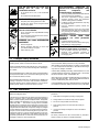
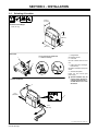
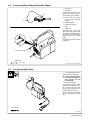
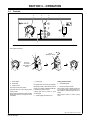
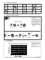
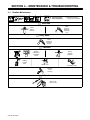
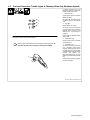
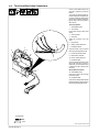
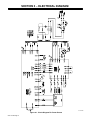
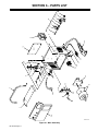
May 1997
Form: OM-182 702
Effective With Serial No. KG198345
OWNER’S
MANUAL
Spectrum® 300 (50/60 Hz)
For Plasma Arc Cutting (PAC)
Rated Cutting
Output
25 A @ 89 Volts DC
At 35% Duty Cycle
Amperes Input at
Rated Output,
50 Hz,
Single-Phase
230 V
KVA
KW
Plasma Gas
17 (0.2*)
4.0 (0.05*)
3.1 (0.04*)
Air Or Nitrogen
Only
Plasma Gas
Flow/
Pressure
4.5 CFM (129
L/min) At 60 PSI
(414 kPa)
Max
OCV
265 Volts DC
*While idling
cover_om 4/95 − ST-801 645
© 1997 MILLER Electric Mfg. Co.
PRINTED IN USA
SECTION 1 − SAFETY FOR PLASMA ARC CUTTING
OM-182 702 −
5/97
safety_pom1 4/95
1-1. Symbol Usage
Means Warning! Watch Out! There are possible hazards with this
procedure! The possible hazards are shown in the adjoining symbols.
Y Marks a special safety message.
. Means NOTE; not safety related.
This group of symbols means Warning! Watch Out! possible ELECTRIC SHOCK, MOVING PARTS,
and HOT PARTS hazards. Consult symbols and related instructions below for necessary actions to
avoid the hazards.
1-2. Plasma Arc Cutting Hazards
WARNING
The symbols shown below are used throughout this manual to call attention to and identify possible
hazards. When you see the symbol, watch out, and follow the related instructions to avoid the hazard. The
safety information given below is only a summary of the more complete safety information found in the
Safety Standards listed in Section 1-4. Read and follow all Safety Standards.
Only qualified persons should install, operate, maintain, and repair this unit.
During operation, keep everybody, especially children, away.
CUTTING can cause fire or explosion.
Hot metal and sparks blow out from the cutting arc.
The flying sparks and hot metal, hot workpiece, and
hot equipment can cause fires and burns. Check
and be sure the area is safe before doing any cutting.
1. Protect yourself and others from flying sparks and hot metal.
2. Do not cut where flying sparks can strike flammable material.
3. Remove all flammables within 35 ft (10.7 m) of the cutting arc. If
this is not possible, tightly cover them with approved covers.
4. Be alert that sparks and hot materials from cutting can easily go
through small cracks and openings to adjacent areas.
5. Watch for fire, and keep a fire extinguisher nearby.
6. Be aware that cutting on a ceiling, floor, bulkhead, or partition can
cause fire on the hidden side.
ELECTRIC SHOCK can kill.
Touching live electrical parts can cause fatal shocks
or severe burns. The torch and work circuit is
electrically live whenever the output is on. The input
power circuit and machine internal circuits are also
live when power is on. Plasma arc cutting requires
higher voltages than welding to start and maintain
the arc (200 to 400 volts dc are common), but also uses torches
designed with safety interlock systems which turn off the machine
when the shield cup is loosened or if tip touches electrode inside the
nozzle. Incorrectly installed or improperly grounded equipment is a
hazard.
1. Do not touch live electrical parts.
2. Wear dry, hole-free insulating gloves and body protection.
3. Insulate yourself from work and ground using dry insulating mats
or covers big enough to prevent any physical contact with the
work or ground.
4. Do not touch torch parts if in contact with the work or ground.
5. Turn off power before checking, cleaning, or changing torch
parts.
6. Disconnect input power before installing or servicing this
equipment. Lockout/tagout input power according to OSHA CFR
1910.147 (see Safety Standards).
7. Properly install and ground this equipment according to its
Owner’s Manual and national, state, and local codes.
FLYING SPARKS AND HOT METAL
can cause injury.
Sparks and hot metal blow out from the cutting arc.
Chipping and grinding cause flying metal.
7. Do not cut on closed containers such as tanks or drums.
8. Connect work cable to the work as close to the cutting area as
practical to prevent cutting current from traveling long, possibly
unknown paths and causing electric shock and fire hazards.
9. Never cut containers with potentially flammable materials inside
− they must be emptied and properly cleaned first.
10. Do not cut in atmospheres containing explosive dust or vapors.
11. Do not cut pressurized cylinders, pipes, or vessels.
12. Do not cut containers that have held combustibles.
13. Wear oil-free protective garments such as leather gloves, heavy
shirt, cuffless trousers, high shoes, and a cap.
14. Do not locate unit on or over combustible surfaces.
15. Remove any combustibles, such as a butane lighter or matches,
from your person before doing any cutting.
8. Check and be sure that input power cord ground wire is properly
connected to ground terminal in disconnect box or that cord plug
is connected to a properly grounded receptacle outlet − always
verify the supply ground.
9. When making input connections, attach proper grounding
conductor first.
10. Frequently inspect input power cord for damage or bare wiring −
replace cord immediately if damaged − bare wiring can kill.
11. Turn off all equipment when not in use.
12. Inspect and replace any worn or damaged torch cable leads.
13. Do not wrap torch cable around your body.
14. Ground the workpiece to a good electrical (earth) ground if
required by codes.
15. Use only well-maintained equipment. Repair or replace damaged
parts at once.
16. Wear a safety harness if working above floor level.
17. Keep all panels and covers securely in place.
18. Do not bypass or try to defeat the safety interlock systems.
19. Use only torch(es) specified in Owner’s Manual.
20. Keep away from torch tip and pilot arc when trigger is pressed.
21. Clamp work cable with good metal-to-metal contact to workpiece
(not piece that will fall away) or worktable as near the cut as
practical.
1. Wear approved face shield or safety goggles with side shields.
2. Wear proper body protection to protect skin.
3. Wear flame-resistant ear plugs or ear muffs to prevent sparks
from entering ears.
OM-182 702 Page 1
ARC RAYS can burn eyes and skin.
Arc rays from the cutting process produce intense
visible and invisible (ultraviolet and infrared) rays
that can burn eyes and skin.
1. Wear face protection (helmet or shield) with correct shade of filter
to protect your face and eyes when cutting or watching. ANSI
Z49.1 (see Safety Standards) suggests a No. 9 shade (with No. 8
as minimum) for all cutting currents less than 300 amperes. Z49.1
adds that lighter filter shades may be used when the arc is hidden
by the workpiece. As this is normally the case with low current
cutting, the shades suggested in Table 1 are provided for the
operator’s convenience.
2. Wear approved safety glasses with side shields.
3. Use protective screens or barriers to protect others from flash
and glare; warn others not to watch the arc.
4. Wear protective clothing made from durable, flame-resistant
material (wool and leather) and foot protection.
FUMES AND GASES can
hazardous to your health.
be
Cutting produces fumes and gases. Breathing these
fumes and gases can be hazardous to your health.
1. Keep your head out of the fumes. Do not breathe the fumes.
2. If inside, ventilate the area and/or use exhaust at the arc to
remove cutting fumes and gases.
3. If ventilation is poor, use an approved air-supplied respirator.
4. Read the Material Safety Data Sheets (MSDSs) and the
manufacturer’s instruction for metals to be cut, coatings, and
cleaners.
PLASMA ARC can cause injury.
The heat from the plasma arc can cause serious
burns. The force of the arc adds greatly to the burn
hazard. The intensely hot and powerful arc can
quickly cut through gloves and tissue.
1. Keep away from the torch tip.
2. Do not grip material near the cutting path.
CYLINDERS can explode if damaged.
Gas cylinders contain gas under high pressure. If
damaged, a cylinder can explode. Since gas
cylinders are normally part of metalworking
processes, be sure to treat them carefully.
1. Protect compressed gas cylinders from excessive heat,
mechanical shocks, slag, open flame, sparks, and arcs.
2. Install and secure cylinders in an upright position by chaining
them to a stationary support or equipment cylinder rack to
prevent falling or tipping.
3. Keep cylinders away from any cutting or other electrical circuits.
NOISE can damage hearing.
Prolonged noise from some cutting applications can
damage hearing if levels exceed limits specified by
OSHA (see Safety Standards).
5. Use approved ear plugs or ear muffs if noise level is high.
6. Warn others nearby about noise hazard.
Table 1. Eye Protection For Plasma Arc Cutting
Current Level In Amperes
Below 20
20 − 40
40 − 60
60 − 80
Minimum Shade Number
#4
#5
#6
#8
5. Work in a confined space only if it is well ventilated, or while
wearing an air-supplied respirator. Fumes from cutting and
oxygen depletion can alter air quality causing injury or death. Be
sure the breathing air is safe.
6. Do not cut in locations near degreasing, cleaning, or spraying
operations. The heat and rays of the arc can react with vapors to
form highly toxic and irritating gases.
7. Do not cut on coated metals, such as galvanized, lead, or
cadmium plated steel, unless the coating is removed from the
cutting area, the area is well ventilated, and if necessary, while
wearing an air-supplied respirator. The coatings and any metals
containing these elements can give off toxic fumes when cut.
8. Do not cut containers with toxic or reactive materials inside or
containers that have held toxic or reactive materials − they must
be emptied and properly cleaned first.
3. The pilot arc can cause burns − keep away from torch tip when
trigger is pressed.
4. Wear proper flame-retardant clothing covering all exposed body
areas.
5. Point torch away from your body and toward work when pressing
the torch trigger − pilot arc comes on immediately.
6. Turn off power source and disconnect input power before
disassembling torch or changing torch parts.
7. Use only torch(es) specified in the Owner’s Manual.
4. Never allow electrical contact between a plasma arc torch and a
cylinder.
5. Never cut on a pressurized cylinder − explosion will result.
6. Use only correct gas cylinders, regulators, hoses, and fittings
designed for the specific application; maintain them and
associated parts in good condition.
7. Turn face away from valve outlet when opening cylinder valve.
8. Keep protective cap in place over valve except when cylinder is in
use or connected for use.
9. Read and follow instructions on compressed gas cylinders,
associated equipment, and CGA publication P-1 listed in Safety
Standards.
1-3. Additional Installation, Operation, And Maintenance Hazards
HOT PARTS can cause severe burns.
1. Do not touch hot parts bare handed.
2. Allow cooling period before working on torch.
FLYING PIECES OF METAL or DIRT can
injure eyes.
1. Wear safety glasses with side shields or face
shield.
OM-182 702 Page 2
FALLING EQUIPMENT can cause
serious personal injury and equipment
damage.
1. Use lifting eye to lift unit only, NOT running gear,
gas cylinders, or any other accessories.
2. Use equipment of adequate capacity to lift unit.
3. If using lift forks to move unit, be sure forks are long
enough to extend beyond opposite side of unit.
FIRE OR EXPLOSION can result from
placing unit on, over, or near
combustible surfaces.
1. Do not locate unit on, over, or near combustible
surfaces.
2. Do not install unit near flammables.
MOVING PARTS can cause injury.
1. Keep away from moving parts such as fans.
2. Keep all doors, panels, covers, and guards closed
and securely in place.
STATIC ELECTRICITY can
parts on circuit boards.
damage
1. Put on grounded wrist strap BEFORE handling
boards or parts.
2. Use proper static-proof bags and boxes to store,
move, or ship PC boards.
OVERUSE can cause OVERHEATED
EQUIPMENT.
1. Allow cooling period.
2. Reduce amperage (thickness) or reduce duty
cycle before starting to cut again.
3. Follow rated duty cycle.
HIGH-FREQUENCY RADIATION can
interfere with radio navigation, safety
services,
computers,
and
communications equipment.
1. Have only qualified persons familiar with electronic
equipment perform this installation.
2. The user is responsible for having a qualified
electrician promptly correct any interference
problem resulting from the installation.
3. If notified by the FCC about interference, stop using
the equipment at once.
4. Have the installation regularly checked and
maintained.
5. Keep high-frequency source doors and panels
tightly shut, keep spark gaps at correct setting, and
use grounding and shielding to minimize the
possibility of interference.
MAGNETIC
CURRENTS
operation.
FIELDS FROM HIGH
can affect pacemaker
1. Pacemaker wearers keep away.
2. Wearers should consult their doctor before going
near plasma arc cutting operations.
SIGNIFICANT DC VOLTAGE exists after
removal of input power on inverters.
1. Turn Off inverter, disconnect input power, and
discharge input capacitors according to
instructions in Maintenance Section before
touching any parts.
1-4. Principal Safety Standards
Safety in Welding and Cutting, ANSI Standard Z49.1, from American
Welding Society, 550 N.W. LeJeune Rd, Miami FL 33126
Safety and Health Standards, OSHA 29 CFR 1910, from Superintendent of Documents, U.S. Government Printing Office, Washington,
D.C. 20402.
Recommended Practices for Plasma Arc Cutting, American Welding
Society Standard AWS C5.2, from American Welding Society, 550
N.W. LeJeune Rd, Miami, FL 33126
Recommended Safe Practices for the Preparation for Welding and
Cutting of Containers That Have Held Hazardous Substances,
American Welding Society Standard AWS F4.1, from American
Welding Society, 550 N.W. LeJeune Rd, Miami, FL 33126
National Electrical Code, NFPA Standard 70, from National Fire Protection Association, Batterymarch Park, Quincy, MA 02269.
Safe Handling of Compressed Gases in Cylinders, CGA Pamphlet
P-1, from Compressed Gas Association, 1235 Jefferson Davis Highway, Suite 501, Arlington, VA 22202.
Code for Safety in Welding and Cutting, CSA Standard W117.2, from
Canadian Standards Association, Standards Sales, 178 Rexdale
Boulevard, Rexdale, Ontario, Canada M9W 1R3.
Safe Practices For Occupation And Educational Eye And Face Protection, ANSI Standard Z87.1, from American National Standards
Institute, 1430 Broadway, New York, NY 10018.
Cutting And Welding Processes, NFPA Standard 51B, from National
Fire Protection Association, Batterymarch Park, Quincy, MA 02269.
1-5. EMF Information
Considerations About Welding And The Effects Of Low Frequency
Electric And Magnetic Fields
The following is a quotation from the General Conclusions Section of
the U.S. Congress, Office of Technology Assessment, Biological
Effects of Power Frequency Electric & Magnetic Fields − Background
Paper, OTA-BP-E-53 (Washington, DC: U.S. Government Printing
Office, May 1989): “. . . there is now a very large volume of scientific
findings based on experiments at the cellular level and from studies
with animals and people which clearly establish that low frequency
magnetic fields can interact with, and produce changes in, biological
systems. While most of this work is of very high quality, the results are
complex. Current scientific understanding does not yet allow us to
interpret the evidence in a single coherent framework. Even more
frustrating, it does not yet allow us to draw definite conclusions about
questions of possible risk or to offer clear science-based advice on
strategies to minimize or avoid potential risks.”
To reduce magnetic fields in the workplace, use the following
procedures:
1. Keep cables close together by twisting or taping them.
2. Arrange cables to one side and away from the operator.
3. Do not coil or drape cables around the body.
4. Keep welding power source and cables as far away as
practical.
5. Connect work clamp to workpiece as close to the weld as
possible.
About Pacemakers:
The above procedures are also recommended for pacemaker
wearers. Consult your doctor for complete information.
OM-182 702 Page 3
SECTION 2 − INSTALLATION
2-1. Selecting A Location
6-3/4 in
(171 mm)
Dimensions And Weight
42 lb (19.1 kg)
17 in
(432 mm)
18 in
(457 mm)
Movement
1
Y Do not move or operate unit
where it could tip.
1
Lifting Handle
Use handle to lift unit.
2
Hand Cart
Use cart or similar device to move
unit.
2
3
Rating Label (On Lower Right
Rear Of Unit)
Use label to determine input power
needs.
4
230 VAC Receptacle
Locate unit near correct input
power supply.
Y Special installation may be
required where gasoline or
volatile liquids are present −
see NEC Article 511 or CEC
Section 20.
Location And Airflow
4
10 in
(254 mm)
3
10 in
(254 mm)
loc_2 3/96 - ST-801 646 / ST-801 647
OM-182 702 Page 4
2-2. Connecting Work Clamp And Gas/Air Supply
1
2
1
Work Clamp
Workpiece
Connect work clamp to a clean,
paint-free location on workpiece, as
close to cutting area as possible.
. Use only clean, dry air with 70
to 150 psi (483 to 1034 kPa)
pressure.
2
3
3
6
4
Gas/Air Inlet Opening
5
Hose
6
Teflon Tape
Obtain hose with 1/4 NPT righthand thread fitting. Wrap threads
with teflon tape (optional) or apply
pipe sealant, and install fitting in
opening. Route hose to gas/air
supply.
Adjust gas/air pressure according
to Section 3-1.
4
From Gas/Air Supply
Air Filter/Regulator
5
Tools Needed:
5/8, 1-1/8 in
Ref. ST-091 547-C / Ref. ST-801 648
2-3. Connecting Input Power
1
2
1
User-Installed 230 VAC Plug
Install proper input power plug.
Y Be sure input power connection meets all applicable national, regional, and local
electrical codes.
2
230 VAC Receptacle
To use maximum output, an individual branch circuit capable of carrying 17 amperes, 230 VAC at 35%
duty cycle, and protected by fuses
or circuit breakers is required.
Connect plug to proper receptacle.
Be sure receptacle can handle
load.
Tools Needed:
ST-801 646
OM-182 702 Page 5
SECTION 3 − OPERATION
3-1. Controls
4
3
2
1
5
Setting Gas/Air Pressure
7
Set To
60 PSI (414 kPa)
6
3
Requires
70-150 PSI
(483-1034 kPa)
Supply
1
Power Switch
4
2
Power Light
Use light to tell if unit is ready for operation.
3
Output Control
Use control to set cutting output.
The yellow zone is for use on 20 A or greater
primary circuits.
Place control in Gas/Air Set position to safely
adjust gas/air pressure. Only gas/air circuit
is activated.
Ready Light
Ready light comes on when Power switch is
placed in On position, indicating that all safety shutdown systems are okay.
If Ready light does not come on, check
Trouble Lights.
5
Trouble Lights (See Section 4-2)
Setting Gas/Air Pressure
6
Air Filter/Regulator
7
Pressure Adjustment Knob
Place Output control in Gas/Air position and
turn on gas/air supply. Lift knob and turn to
adjust pressure. Push knob down to lock in
setting.
Place Output control in desired cutting
output.
Ref. ST-801 306-B / Ref. SC-181 264-A
OM-182 702 Page 6
3-2. Symbols And Definitions
A
V
Amperes
Plasma Arc Cutting
(PAC)
Adjust Air/Gas
Pressure
Air Pressure
Volts
Increase
No − Do Not Do
This
Temperature
Protective Earth
(Ground)
Loose Shield Cup
Input
Voltage Input
On
Off
Loose Shield Cup
3-3. Duty Cycle And Overheating
Duty Cycle is percentage of 10 minutes that unit can cut at rated load
without overheating.
If unit overheats, thermostat(s)
opens, output stops, Temperature
trouble light goes On, and cooling
fan runs. Wait fifteen minutes for
unit to cool or Temperature light to
go Off. Reduce amperage or duty
cycle before cutting or gouging.
35% Duty Cycle At 25 Amperes
Y Exceeding duty cycle can
damage unit and void
warranty.
3-1/2 Minutes Cutting
Overheating
6-1/2 Minutes Resting
A or V
0
15
Minutes
OR
Reduce Duty Cycle
sduty1* 5/95
3-4. Cutting Speed
Recommended production cutting speed vs. material thickness is
approximately 10 imp at 5/16 in mild steel thickness at max setting.
The cutting speed curves show the
recommended maximum cutting
speed capabilities of the power
source and torch for mild steel of
various thickness.
Cut at speeds below the lines
shown to avoid poor cuts and torch
wear.
ST-179 507
OM-182 702 Page 7
SECTION 4 − MAINTENANCE & TROUBLESHOOTING
4-1. Routine Maintenance
Y Disconnect power
before maintaining.
. Maintain more often
during severe conditions.
Each Use
Check
Torch Tip,
Electrode,
And Shield
Cup
Check
Gas/Air
Pressure
Every Week
Check
Shield Cup
Shutdown
System
3 Months
Replace
Damaged Or
Unreadable
Labels
Replace
Cracked
Parts
Service
Air Filter/
Regulator
Gas/Air Hose
Torch Body, Cable
Tape Torn
Outer
Covering
6 Months
Blow Out Or
Vacuum Inside
OM-182 702 Page 8
4-2. Overload Protection: Trouble Lights & Checking Shield Cup Shutdown System
If certain problems occur, the
Ready light goes off, a trouble light
comes on, and output stops.
1
1
2
3
Pressure Light
Lights if gas/air pressure is below
40 PSI (276 kPa).
Turn power Off, and check for proper gas/air pressure (see Section
3-1).
2
Cup Light
Lights if shield cup is loose.
Turn power Off, and check shield
cup connection (see torch Owner’s
Manual). Power must be reset
whenever the cup shutdown is
activated.
Checking Torch Shield Cup Shutdown System
Check shield cup shutdown system
once a week.
3
Temperature Light
Lights if power source overheats
(see Section 3-3).
Power must be reset whenever the cup shutdown system is activated. Always turn Off power when changing or checking consumables.
4
4
Torch Shield Cup
Turn Power On and loosen shield
cup. If shutdown system works
properly, Ready light goes off and
Cup light comes on. If not, turn power Off and check for proper gas/air
pressure (see Section 3-1),
blocked or leaking hose, or loose
shield cup (see torch Owner’s Manual).
If system works properly, retighten
cup and reset power.
Ref. ST-181 264-A / Ref. ST-801 300-A
OM-182 702 Page 9
4-3. Torch And Work Cable Connections
If torch or work cable needs to be
removed or replaced, proceed as
follows:
Turn power Off, and disconnect input power plug from receptacle. Remove top and screws holding front
panel in place. Without disconnecting any plugs, move front panel to
allow access.
Torch Connections
1
Strain Relief Clamp
2
Torch Cable
Insert cable through strain relief
clamp.
8
9
3
Gas Connector
4
Gas Valve
Install gas connector onto gas
valve.
2
5
11
6
Plug PLG18
6
Safety Control Board PC2
7
Receptacle RC18
Connect PLG18 to RC18. Route
leads along existing lead bundle.
13
10
7
5
3
8
Female Friction Terminals
9
Male Friction Terminal
10 Power Control Board PC1
11 Receptacle RC4
Connect female terminals to leads
23 and 24 from RC4 (connect to
either lead). Connect male terminal
to lead 25 from RC4. Route leads
as shown.
1
Work Cable Connections
12 Strain Relief Clamp
Insert work clamp lead through
strain relief clamp.
4
12
13 Receptacle RC6
Connect work clamp lead to lead 20
from RC6 (leads not shown). Route
leads along existing lead bundle.
Tools Needed:
5/8 in
ST-801 649 / Ref. ST-801 300-B
OM-182 702 Page 10
4-4. Troubleshooting
Trouble
Remedy
No pilot arc; difficulty in establishing an Clean or replace worn consumables as necessary (see torch Owner’s Manual).
arc.
Check for damaged torch or torch cable (see torch Owner’s Manual).
Have Factory Authorized Service Agent check control relay CR6, power control board PC1, safety control board PC2, gas valve GS1, rectifier SR1, and check gas/air system for leaks.
No cutting output; Power light off; Place Power switch in On position.
Trouble lights off; Ready light off; fan motor FM does not run.
Place line disconnect device in On position (see Section 2-3).
Check line fuse(s) and replace if needed or reset circuit breakers (see Section 2-3).
Have Factory Authorized Service Agent check power switch S1, input resistor R2, control relay CR6,
safety control board PC2, and transformer T1.
No cutting output; Power light on; Ready Be sure work clamp is connected.
light on; Trouble lights off; fan motor FM
running.
Clean or replace worn consumables as necessary (see torch Owner’s Manual).
Have Factory Authorized Service Agent check contactor W, control relay CR3, and safety control board
PC2.
No cutting output; Power light on; Ready Reset Power switch.
light off; Trouble lights off; fan motor FM
running.
Have Factory Authorized Service Agent check contactor CR7, control relay CR6, safety control board
PC2, input resistor R2, power control board PC1. Check for proper torch lead connections. Check operation of gas valve GS1, and check gas/air system for leaks.
No control of output.
Have Factory Authorized Service Agent check power control board PC1, and safety control board PC2.
No gas/air flow; Power light on; Ready Have Factory Authorized Service Agent check for proper torch connections, and check power control
light on; Trouble lights off; fan motor FM board PC1. Check operation of gas valve GS1, and check gas/air system for leaks.
running.
Pressure Trouble light On; Ready light Check for correct gas/air pressure adjustment (see Section 3-1).
off.
Check for sufficient gas/air supply pressure (see Section 2-2).
Check for dirty air filter/regulator and clean, if needed (see manufacturer’s instructions).
Cup Trouble light On; Ready light off.
Check torch shield cup (see Section 4-2).
Have Factory Authorized Service Agent check for proper torch connections, and check safety control
board PC2
Temperature Trouble light On; Ready Thermostat TP1 open (overheating). Allow fan to run; the thermostat closes when the unit has cooled (see
light off.
Section 4-2).
Have Factory Authorized Service Agent check safety control board PC2 and transformer T1.
Fan motor FM does not run; Power light Have Factory Authorized Service Agent check fan motor connections.
and Ready light both On.
Trouble lights not working.
Have Factory Authorized Service Agent check safety control board PC2.
OM-182 702 Page 11
SECTION 5 − ELECTRICAL DIAGRAM
SC-182 866
Figure 6-1. Circuit Diagram For Power Source
OM-177 545 Page 12
NOTES
OM-182 702 Page 13
38
1
34
35
37
33
2
9
31
32
8
7
36
30
6
10
3
5
11
4
5
29
28
12
27
26
PC1
13
25
14
15
17
18
19
20
16
21
22
23
24
SECTION 6 − PARTS LIST
ST-801 644
Figure 6-1. Main Assembly
OM-182 702 Page 14
Item
No.
Dia.
Mkgs.
Part
No.
Description
Quantity
Figure 6-1. Main Assembly
. . . 1 . . . . . . . . . . . . . 175 055 . . COVER, top . . . . . . . . . . . . . . . . . . . . . . . . . . . . . . . . . . . . . . . . . . . . . . . . . . . . 1
. . . 2 . . . . . . . . . . . . . 175 145 . . HANDLE, lifting . . . . . . . . . . . . . . . . . . . . . . . . . . . . . . . . . . . . . . . . . . . . . . . . . 1
. . . 3 . . . . . . . . . . . . . 175 366 . . REGULATOR ASSEMBLY, (consisting of) . . . . . . . . . . . . . . . . . . . . . . . . . . 1
. . . 4 . . . . . . . . . . . . . 177 347 . . . . HOSE, SAE .187 ID x .410 OD x 6.500 . . . . . . . . . . . . . . . . . . . . . . . . . . . 1
. . . 5 . . . . . . . . . . . . . 175 999 . . . . FITTING, brs barbed fem 3/16tbg x 1/8NPT . . . . . . . . . . . . . . . . . . . . . . . 1
. . . 6 . . . . . . . . . . . . . 174 668 . . . . REGULATOR/FILTER, 250 PSIG in 100 PSIG max out . . . . . . . . . . . . . 1
. . . 7 . . . . . . . . . . . . . 176 518 . . . . FITTING, pipe brs elbow st 1/4NPT . . . . . . . . . . . . . . . . . . . . . . . . . . . . . . 1
. . . 8 . . . . . . . . . . . . . 176 517 . . . . FITTING, pipe brs nipple L 1/4NPT x 2.500 . . . . . . . . . . . . . . . . . . . . . . . 1
. . . 9 . . . . . . . . . . . . . 602 963 . . . . FITTING, pipe brs coupling 1/4NPT . . . . . . . . . . . . . . . . . . . . . . . . . . . . . . 1
. . . . . . . . . . . . . . . . . . . . 118 134 . . . . FITTING, pipe brs plug shhd 1/4NPT . . . . . . . . . . . . . . . . . . . . . . . . . . . . . 1
. . . 10 . . . . . . . . . . . . . 174 783 . . . . GAUGE, pressure air 0-160 PSI 1/8NPT . . . . . . . . . . . . . . . . . . . . . . . . . . 1
. . . 11 . . . . . . . . . . . . . 174 562 . . . . BRACKET, mtg air filter/regulator . . . . . . . . . . . . . . . . . . . . . . . . . . . . . . . . 1
. . . 12 . . . . . . . . . . . . . 176 123 . . . . FITTING, plstc Qdisc elbow 1/4NPT x 1/4 OD tubing . . . . . . . . . . . . . . . 1
. . . . . . . . . . . . . . . . . . . 181 693 . . . . GASKET, NPRN control knob cover . . . . . . . . . . . . . . . . . . . . . . . . . . . . . . 1
. . . 13 . . . . PC1 . . . 184 973 . . CIRCUIT CARD ASSEMBLY, power control . . . . . . . . . . . . . . . . . . . . . . . . . 1
. . . . . . . . . . PLG1 . . . 158 720 . . CONNECTOR & SOCKETS . . . . . . . . . . . . . . . . . . . . . . . . . . . . . . . . . . . . . . 1
. . . . . . . . . . PLG4 . . . 168 071 . . CONNECTOR & SOCKETS . . . . . . . . . . . . . . . . . . . . . . . . . . . . . . . . . . . . . . 1
. . . . . . . . . . PLG6 . . . 176 121 . . CONNECTOR, rect 1 row plug . . . . . . . . . . . . . . . . . . . . . . . . . . . . . . . . . . . . 1
. . . . . . . . . . . . . . . . . . . 134 201 . . STAND-OFF SUPPORT, PC card . . . . . . . . . . . . . . . . . . . . . . . . . . . . . . . . . 3
. . . . . . . . . . . . . . . . . . . 070 026 . . STAND-OFF, 6-32 x .437 lg . . . . . . . . . . . . . . . . . . . . . . . . . . . . . . . . . . . . . . . 4
. . . 14 . . . . . FM . . . . 088 566 . . MOTOR FAN, 115V 50/60 Hz 3100RPM . . . . . . . . . . . . . . . . . . . . . . . . . . . . 1
. . . 15 . . . . . . . . . . . . . 175 053 . . CASE, base/back/sides . . . . . . . . . . . . . . . . . . . . . . . . . . . . . . . . . . . . . . . . . . 1
. . . 16 . . . . . . . . . . . . . 175 365 . . AIR VALVE ASSEMBLY, (consisting of) . . . . . . . . . . . . . . . . . . . . . . . . . . . . 1
. . . 17 . . . . . . . . . . . . . 177 346 . . . . TUBING, pneumatic .250 OD x .170 ID x 13.500 . . . . . . . . . . . . . . . . . . . 1
. . . 18 . . . . . . . . . . . . . 176 122 . . . . FITTING, plstc Qdisc straight 1/8NPT x 1/4 OD . . . . . . . . . . . . . . . . . . . . 1
. . . 19 . . . . . S3 . . . . 174 670 . . . . SWITCH, pressure air 40PSI fixed . . . . . . . . . . . . . . . . . . . . . . . . . . . . . . . 1
. . . 20 . . . . . . . . . . . . . 602 965 . . . . FITTING, pipe brs tee 1/8NPT . . . . . . . . . . . . . . . . . . . . . . . . . . . . . . . . . . . 1
. . . 21 . . . . . . . . . . . . . 073 655 . . . . FITTING, pipe brs nipple hex 1/8NPT . . . . . . . . . . . . . . . . . . . . . . . . . . . . 1
. . . 22 . . . . GS1 . . . 175 827 . . . . VALVE, 24VAC 3 way 1/8NPT 5/32 orf 100PSI . . . . . . . . . . . . . . . . . . . . 1
. . . 23 . . . . . . . . . . . . . 157 057 . . . . BRACKET, valve . . . . . . . . . . . . . . . . . . . . . . . . . . . . . . . . . . . . . . . . . . . . . . 1
. . . 24 . . . . . . . . . . . . . 175 998 . . . . FITTING, pipe brs adaptor 1/8NPT/.375-24 LH . . . . . . . . . . . . . . . . . . . . 1
. . . 25 . . . . . . . . . . . . . 176 499 . . ICE-25C PLASMA ARC CUTTING TORCH, 15ft (see OM-1593) . . . . . . 1
. . . 25 . . . . . . . . . . . . ♦176 822 . . ICE-25C PLASMA ARC CUTTING TORCH, 25ft (see OM-1593) . . . . . . 1
. . . 26 . . . . Work . . . 186 574 . . CABLE WORK 15ft, (consisting of) . . . . . . . . . . . . . . . . . . . . . . . . . . . . . . . . 1
. . . . . . . . . . . . . . . . . . . 601 222 . . . . CLAMP, univ 50A . . . . . . . . . . . . . . . . . . . . . . . . . . . . . . . . . . . . . . . . . . . . . . 1
. . . . . . . . . . . . . . . . . . . 600 848 . . . . WIRE, strd 12ga 600V (order by ft) . . . . . . . . . . . . . . . . . . . . . . . . . . . . . . 15ft
. . . . . . . . . . . . . . . . . . . 176 089 . . . . TUBING, plstc PVC blk .250 ID x .375 OD x 9.000 . . . . . . . . . . . . . . . . . 1
. . . 27 . . . . . . . . . . . . . 020 577 . . BUSHING, strain relief .120/.150 ID x .500mtg . . . . . . . . . . . . . . . . . . . . . . 1
. . . 28 . . . . . . . . . . . . . 019 663 . . MOUNT, nprn . . . . . . . . . . . . . . . . . . . . . . . . . . . . . . . . . . . . . . . . . . . . . . . . . . . 6
. . . 29 . . . . CR2 . . . 175 828 . . CONTACTOR, def prp 25A 1P 24VAC . . . . . . . . . . . . . . . . . . . . . . . . . . . . . 1
. . . . . . . . . . . . . . . . . . . 072 253 . . STUD, connection . . . . . . . . . . . . . . . . . . . . . . . . . . . . . . . . . . . . . . . . . . . . . . . 1
. . . 30 . . . . . . . . . . . . . 175 144 . . BRACKET, transformer . . . . . . . . . . . . . . . . . . . . . . . . . . . . . . . . . . . . . . . . . . 1
. . . 31 . . . . . T1 . . . . 178 062 . . TRANSFORMER, main power 115/230 50/60Hz . . . . . . . . . . . . . . . . . . . . . 1
. . . 32 . . . . . R1 . . . . 176 505 . . RESISTOR, WW fxd 338W 1.5 ohm . . . . . . . . . . . . . . . . . . . . . . . . . . . . . . . 1
. . . . . . . . . . . . . . . . . . . 059 726 . . INSULATOR, end . . . . . . . . . . . . . . . . . . . . . . . . . . . . . . . . . . . . . . . . . . . . . . . 2
. . . 33 . . . . . . . . . . . . . 175 058 . . BRACKET, resistor . . . . . . . . . . . . . . . . . . . . . . . . . . . . . . . . . . . . . . . . . . . . . . 1
. . . 34 . . . . VR1 . . . 178 393 . . VARISTOR . . . . . . . . . . . . . . . . . . . . . . . . . . . . . . . . . . . . . . . . . . . . . . . . . . . . . 1
. . . 35 . . . . SR1 . . . 179 682 . . RECTIFIER, integ 40A 800V . . . . . . . . . . . . . . . . . . . . . . . . . . . . . . . . . . . . . . 1
. . . . . . . . . . . . . . . . . . . 141 690 . . GROMMET . . . . . . . . . . . . . . . . . . . . . . . . . . . . . . . . . . . . . . . . . . . . . . . . . . . . . 2
. . . 36 . . . . . . . . . . . . . 139 041 . . BUSHING, strain relief .455/.629 ID x 1.115mtg . . . . . . . . . . . . . . . . . . . . . 2
. . . 37 . . . . . . . . . . . . . 182 521 . . CABLE, power 10ft 14ga 3/C . . . . . . . . . . . . . . . . . . . . . . . . . . . . . . . . . . . . . 1
. . . . . . . . . . . FL1 . . . 181 262 . . FILTER, common mode 25A . . . . . . . . . . . . . . . . . . . . . . . . . . . . . . . . . . . . . . 1
. . . 38 . . . . . . . . . . . . . . . . . . . . . . . . FRONT PANEL, (consisting of) . . . . . . . . . . . . . . . . . . . . . . . . . . . . . . . . . . . . 1
. . . . . . . . . . . . . . . . . . +181 717 . . . . PANEL, front . . . . . . . . . . . . . . . . . . . . . . . . . . . . . . . . . . . . . . . . . . . . . . . . . . 1
. . . . . . . . . . . . . . . . . . . 174 991 . . . . KNOB, pointer . . . . . . . . . . . . . . . . . . . . . . . . . . . . . . . . . . . . . . . . . . . . . . . . 1
. . . . . . . . . . . . . . . . . . . . . . . . . . . . . . . . NAMEPLATE, (order by model and serial number) . . . . . . . . . . . . . . . . . 1
. . . . . . . . . . . . . . . . . . . 159 036 . . . . LENS, LED clear . . . . . . . . . . . . . . . . . . . . . . . . . . . . . . . . . . . . . . . . . . . . . . 5
. . . . . . . . . . . . . . . . . . . 159 035 . . . . CLIP, lens retainer LED . . . . . . . . . . . . . . . . . . . . . . . . . . . . . . . . . . . . . . . . . 5
. . . . . . . . . . . S1 . . . . . 124 511 . . . . SWITCH, toggle DPST 40A 600VAC . . . . . . . . . . . . . . . . . . . . . . . . . . . . . 1
OM-182 702 Page 15
. . . . . . . . . . . . . . . . . . . 181 708 . . . . GASKET, switch . . . . . . . . . . . . . . . . . . . . . . . . . . . . . . . . . . . . . . . . . . . . . . . 1
Item
Dia.
Part
Description
No.
Mkgs.
No.
Quantity
Figure 6-1. Main Assembly (Continued)
. . . 38 . . . . . . . . . . . . . . . . . . . . . . . . FRONT PANEL, (consisting of) (Continued)
. . . . . . . . . . CR7 . . . 149 823 . . . . RELAY, encl 12VDC SPST . . . . . . . . . . . . . . . . . . . . . . . . . . . . . . . . . . . . . .
. . . . . . . . . . . R2 . . . . 182 486 . . . . THERMISTOR, PTC 8A 250V . . . . . . . . . . . . . . . . . . . . . . . . . . . . . . . . . . .
. . . . . . . . . . C1,2 . . . 178 981 . . . . CAPACITOR, . . . . . . . . . . . . . . . . . . . . . . . . . . . . . . . . . . . . . . . . . . . . . . . . .
. . . . . . . . . . . . . . . . . . . 178 956 . . . . MAGNET, adhesive mounted . . . . . . . . . . . . . . . . . . . . . . . . . . . . . . . . . . . .
. . . . . . . . . . . . . . . . . . . 183 805 . . . . LABEL, warning precautionary . . . . . . . . . . . . . . . . . . . . . . . . . . . . . . . . . .
. . . . . . . . . . . . . . . . . . . 179 190 . . . . LABEL, warning shock . . . . . . . . . . . . . . . . . . . . . . . . . . . . . . . . . . . . . . . . .
. . . . . . . . PLG20,22 . 167 640 . . . . CONNECTOR & SOCKETS . . . . . . . . . . . . . . . . . . . . . . . . . . . . . . . . . . . .
. . . . . . . . . . PC2 . . . 183 712 . . . . CIRCUIT CARD ASSEMBLY, safety control . . . . . . . . . . . . . . . . . . . . . . .
. . . . . . . . . PLG11 . . 169 240 . . . . CONNECTOR & SOCKETS . . . . . . . . . . . . . . . . . . . . . . . . . . . . . . . . . . . .
. . . . . . . . . . . . . . . . . . . 176 478 . . STAND-OFF SUPPORT, PC card . . . . . . . . . . . . . . . . . . . . . . . . . . . . . . . . .
. . . . . . . . . . . . . . . . . . . 178 595 . . CONSUMABLE STORAGE BOX, (consisting of) . . . . . . . . . . . . . . . . . . . .
. . . . . . . . . . . . . . . . . . . 178 593 . . . . PARTITION . . . . . . . . . . . . . . . . . . . . . . . . . . . . . . . . . . . . . . . . . . . . . . . . . . .
. . . . . . . . . . . . . . . . . . . 178 792 . . . . DOOR, storage box . . . . . . . . . . . . . . . . . . . . . . . . . . . . . . . . . . . . . . . . . . . .
. . . . . . . . . . . . . . . . . . . 176 655 . . ELECTRODE, 25A . . . . . . . . . . . . . . . . . . . . . . . . . . . . . . . . . . . . . . . . . . . . . .
. . . . . . . . . . . . . . . . . . . 176 656 . . TIP, 25A . . . . . . . . . . . . . . . . . . . . . . . . . . . . . . . . . . . . . . . . . . . . . . . . . . . . . . .
+When ordering a component originally displaying a precautionary label, the label should also be ordered.
♦Optional
BE SURE TO PROVIDE MODEL AND SERIAL NUMBER WHEN ORDERING REPLACEMENT PARTS.
OM-182 702 Page 16
1
1
1
1
1
1
1
1
1
4
1
1
1
3
3
Effective January 1, 1997
(Equipment with a serial number preface of “KH” or newer)
This limited warranty supersedes all previous Miller warranties and is exclusive with no other
guarantees or warranties expressed or implied.
LIMITED WARRANTY − Subject to the terms and conditions
below, Miller Electric Mfg. Co., Appleton, Wisconsin,
warrants to its original retail purchaser that new Miller
equipment sold after the effective date of this limited warranty
is free of defects in material and workmanship at the time it is
shipped by Miller. THIS WARRANTY IS EXPRESSLY IN
LIEU OF ALL OTHER WARRANTIES, EXPRESS OR
IMPLIED, INCLUDING
THE
WARRANTIES OF
MERCHANTABILITY AND FITNESS.
Within the warranty periods listed below, Miller will repair or
replace any warranted parts or components that fail due to
such defects in material or workmanship. Miller must be
notified in writing within thirty (30) days of such defect or
failure, at which time Miller will provide instructions on the
warranty claim procedures to be followed.
Miller shall honor warranty claims on warranted equipment
listed below in the event of such a failure within the warranty
time periods. All warranty time periods start on the date that
the equipment was delivered to the original retail purchaser,
or one year after the equipment is sent to a North American
distributor or eighteen months after the equipment is sent to
an International distributor.
1.
2.
Warranty Questions?
Call
1-800-4-A-MILLER
for your local
Miller distributor.
3.
5 Years Parts − 3 Years Labor
*
Original main power rectifiers
*
Inverters (input and output rectifiers only)
3 Years — Parts and Labor
*
Transformer/Rectifier Power Sources
*
Plasma Arc Cutting Power Sources
*
Semi-Automatic and Automatic Wire Feeders
*
Inverter Power Supplies
*
Intellitig
*
Robots
*
Engine Driven Welding Generators
(NOTE: Engines are warranted separately by the
engine manufacturer.)
1 Year — Parts and Labor
*
Motor Driven Guns (w/exception of Spoolmate 185)
*
Process Controllers
*
Positioners and Controllers
*
Automatic Motion Devices
*
Orbital Weld Heads
*
IHPS Power Sources
*
Water Coolant Systems
*
HF Units
*
Grids
*
Spot Welders
*
Load Banks
*
SDX Transformers
*
Miller Cyclomatic Equipment
*
Running Gear/Trailers
*
Plasma Cutting Torches (except APT, ZIPCUT &
PLAZCUT Models)
*
Deutz Engines (outside North America)
*
Field Options
(NOTE: Field options are covered under True Blue®
for the remaining warranty period of the product they
are installed in, or for a minimum of one year —
whichever is greater.)
4.
6 Months — Batteries
5.
90 Days — Parts and Labor
*
MIG Guns/TIG Torches
*
APT, ZIPCUT & PLAZCUT Model Plasma Cutting
Torches
*
Remote Controls
*
Accessory Kits
*
Replacement Parts (No labor)
*
Spoolmate 185
Miller’s True Blue® Limited Warranty shall not apply to:
1.
Items furnished by Miller, but manufactured by others,
such as engines or trade accessories. These items are
covered by the manufacturer’s warranty, if any.
2.
Consumable components; such as contact tips, cutting
nozzles, contactors, brushes, slip rings, relays or parts
that fail due to normal wear.
3.
Equipment that has been modified by any party other
than Miller, or equipment that has been improperly
installed, improperly operated or misused based upon
industry standards, or equipment which has not had
reasonable and necessary maintenance, or equipment
which has been used for operation outside of the
specifications for the equipment.
MILLER PRODUCTS ARE INTENDED FOR PURCHASE
AND USE BY COMMERCIAL/INDUSTRIAL USERS AND
PERSONS TRAINED AND EXPERIENCED IN THE USE
AND MAINTENANCE OF WELDING EQUIPMENT.
In the event of a warranty claim covered by this warranty, the
exclusive remedies shall be, at Miller’s option: (1) repair; or
(2) replacement; or, where authorized in writing by Miller in
appropriate cases, (3) the reasonable cost of repair or
replacement at an authorized Miller service station; or (4)
payment of or credit for the purchase price (less reasonable
depreciation based upon actual use) upon return of the
goods at customer’s risk and expense. Miller’s option of
repair or replacement will be F.O.B., Factory at Appleton,
Wisconsin, or F.O.B. at a Miller authorized service facility as
determined by Miller. Therefore no compensation or
reimbursement for transportation costs of any kind will be
allowed.
TO THE EXTENT PERMITTED BY LAW, THE REMEDIES
PROVIDED HEREIN ARE THE SOLE AND EXCLUSIVE
REMEDIES. IN NO EVENT SHALL MILLER BE LIABLE
FOR DIRECT, INDIRECT, SPECIAL, INCIDENTAL OR
CONSEQUENTIAL DAMAGES (INCLUDING LOSS OF
PROFIT), WHETHER BASED ON CONTRACT, TORT OR
ANY OTHER LEGAL THEORY.
ANY EXPRESS WARRANTY NOT PROVIDED HEREIN
AND ANY IMPLIED WARRANTY, GUARANTY OR
REPRESENTATION AS TO PERFORMANCE, AND ANY
REMEDY FOR BREACH OF CONTRACT TORT OR ANY
OTHER LEGAL THEORY WHICH, BUT FOR THIS
PROVISION, MIGHT ARISE BY IMPLICATION,
OPERATION OF LAW, CUSTOM OF TRADE OR COURSE
OF DEALING, INCLUDING ANY IMPLIED WARRANTY OF
MERCHANTABILITY OR FITNESS FOR PARTICULAR
PURPOSE, WITH RESPECT TO ANY AND ALL
EQUIPMENT FURNISHED BY MILLER IS EXCLUDED
AND DISCLAIMED BY MILLER.
Some states in the U.S.A. do not allow limitations of how long
an implied warranty lasts, or the exclusion of incidental,
indirect, special or consequential damages, so the above
limitation or exclusion may not apply to you. This warranty
provides specific legal rights, and other rights may be
available, but may vary from state to state.
In Canada, legislation in some provinces provides for certain
additional warranties or remedies other than as stated
herein, and to the extent that they may not be waived, the
limitations and exclusions set out above may not apply. This
Limited Warranty provides specific legal rights, and other
rights may be available, but may vary from province to
province.
Owner’s Record
Please complete and retain with your personal records.
Model Name
Serial/Style Number
Purchase Date
(Date which equipment was delivered to original customer.)
Distributor
Address
City
State
Zip
Resources Available
Always provide Model Name and Serial/Style Number.
Contact your Distributor for:
Welding Supplies and Consumables
To locate distributor nearest you call
1-800-4-A-Miller.
Options and Accessories
Personal Safety Equipment
Miller Electric Mfg. Co.
Service and Repair
Replacement Parts
Training (Schools, Videos, Books)
Owner’s Manuals
Technical Manuals (Servicing Information
and Parts)
Circuit Diagrams
Welding Process Handbooks
Contact the Delivering Carrier for:
For assistance in filing or settling claims,
contact your distributor and/or equipment
manufacturer’s Transportation Department.
PRINTED IN USA
File a claim for loss or damage during
shipment.
© 1997 Miller Electric Mfg. Co.
An Illinois Tool Works Company
1635 West Spencer Street
Appleton, WI 54914 USA
International Headquarters−USA
Phone: 920-734-9821
USA & Canada FAX: 920-735-4134
International FAX: 920-735-4125
European Headquarters −
United Kingdom
Phone: 44 (0) 1625-525556
FAX: 44 (0) 1625-537553


![General design guidance [PDF 950KB]](http://vs1.manualzilla.com/store/data/005804077_1-5fec14441b6361d04901f77e13b8a9c0-150x150.png)