1
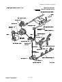
Dell 5130cn Finisher
Service Manual
10 Jun 2009
Information in this document is subject to change without notice.
2010 Dell Inc. All rights reserved.
Reproduction in any manner whatsoever without the written permission of Dell Inc.is strictly forbidden.
Trademarks used in this text: Dell and the DELL logo are trademarks of Dell Inc.
Other trademarks and trade names may be used in this document to refer to the entities claiming the marks and
names of their products. Dell Inc. disclaims any proprietary interest in trademarks and trade names other than
its own.
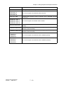
Version record
Refer to the portion indicated by change bar in each section.
Also refer to the reasons in table below.
Version
Issue date
1st
March 31, 2009
2nd
June 10, 2009
Note
1st issued
2nd issued
Introduction
- The illustration was reviewed by the externals
change.
- The illustration was changed or added.
Chapter 3:RRP
- The procedure of the RRP was reviewed
according to the specification change.
Chapter 4:Plug/Jack Connector Locations
- The illustration was changed.
Chapter 6:Principles of Operation
- The illustration was reviewed by the externals
change.
- "3.3.2.3 Sheet/Envelope Select Lever" was
added.
Chapter 8:Printer Specifications
- The printer specification was reviewed
according to the specification change.
Introduction CONTENTS
Cautions................................................................................................................................ i
1. About this manual............................................................................................................. ii
2. Marks giving caution......................................................................................................... ii
3. Related documents........................................................................................................... ii
4. Safety ...............................................................................................................................iii
4.1 Power source ......................................................................................................................................... iii
4.2 Driving units ...........................................................................................................................................iv
4.3 Warning/caution labels............................................................................................................................v
Unpacking the Finisher........................................................................................................ vi
Finisher Service Manual
Version 3 2009.07.03
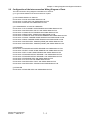
Cautions
Operation contents of this document may be subject to modification without notice.
Dell Inc. will not assume responsibility for accidental or incidental damages resulting from technical
or editorial errors or omissions in this manual, the issue of this manual, the execution of descriptions
in this manual, or the use of this manual.
This document is protected by copyright. Do not photocopy or duplicate any part of this document in
any form without written permission from Dell Inc.
Finisher Service Manual
Version 1 2009.03.31
i
1. About this manual
This manual is a standard service manual of Dell Inc. containing information required for maintenance
of this finisher.
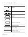
2. Marks giving caution
Maintenance operations requiring special cautions or additional information regarding descriptions in
this manual are presented as "Warning," "Caution," or "Note," depending on their nature.
If instructions are not observed, death or serious injury may result.
If instructions are not observed, injuries to workers or physical damage to assets
(including this finisher) may result.
Essentials for procedures, steps, rules, and others.
Reference Incidental information to descriptions.
3. Related documents
- Instruction manuals (standard manuals)
Describe the operation and handling of this finisher.
- Performance specifications
Describe in detail various specifications of this finisher.
(In the event of a discrepancy between this manual and the performance specifications, the
performance specifications take precedence.)
- Spare parts list
Information on maintenance parts (spare parts) for this finisher.
Finisher Service Manual
Version 1 2009.03.31
ii
4. Safety
To prevent possible accidents during maintenance operation, you should observe strictly the "Warning"
and "Caution" information in this manual.
Avoid dangerous operations and operations out of the scope of this manual.
Various processes not covered by this manual may be required in actual operations, and should be
performed carefully, always giving attention to safety.
4.1 Power source
Keep the power plug disconnected during the maintenance operation to prevent electric shock, burns
and other damages.
If the power supply should be kept connected to measure voltage or for other similar reasons, take
sufficient care to prevent electric shock, by following the procedures in this manual.
While the printer is on, never touch live parts if not required.
Power is supplied to the power switch / inlet even while the printer is off. Never
touch its live components.
Do not touch live parts unless otherwise specified.
Tbt00502KB
Finisher Service Manual
Version 2 2009.06.10
iii
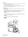
4.2 Driving units
When servicing gears or other driving units, be sure to turn off the power switch and unplug the power
cord. Drive them manually when required.
Do not do the print work removing the cover of the finisher to confirm the operation
of driving part.
Finisher Service Manual
Version 1 2009.03.31
iv
4.3 Warning/caution labels
Warning labels and caution labels are attached to this finisher to prevent accidents Check those labels
for their peeling or stains when servicing the finisher.
Tbt00503KC
Finisher Service Manual
Version 3 2009.07.03
v
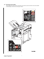
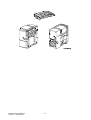
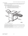
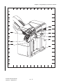
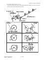
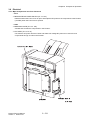
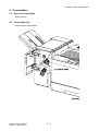
Unpacking the Finisher
The finisher must be carried horizontally with three or more persons.
Take extreme care to avoid personal injuries.
Check visually the finisher for evidence of any damages.
Peel all tapes off the finisher.
Tbt00504KA
Finisher Service Manual
Version 2 2009.06.10
vi
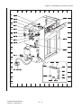
Tbt00505KA
Finisher Service Manual
Version 2 2009.06.10
vii
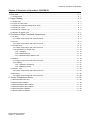
TABLE OF CONTENTS
Chapter 1 Troubleshooting ......................................................... 1 - 1 (Dell 5130cn Service Manual)
Chapter 2 Operation of Diagnostic ............................................. 2 - 1 (Dell 5130cn Service Manual)
Chapter 3 Removal and Replacement Procedures ........................................................3 - 1
Chapter 4 Plug/Jack(P/J) Connector Locations..............................................................4 - 1
Chapter 5 Parts List.................................................................... 5 - 1 (Dell 5130cn Service Manual)
Chapter 6 Principles of Operation ..................................................................................6 - 1
Chapter 7 Wiring Diagrams and Signal Information .......................................................7 - 1
Chapter 8 Printer Specifications .....................................................................................8 - 1
Finisher Service Manual
Version 3 2009.07.03
viii
Chapter 3 Removal and Replacement Procedures (RRPs)
Chapter 3 Removal and Replacement Procedures (RRPs) CONTENTS
1. Removal and Replacement Procedures (RRPs) .........................................................3 - 1
1.1 Before Starting Service Procedure ................................................................................................... 3 - 1
1.2 General Notes................................................................................................................................... 3 - 2
Removal Flows ................................................................................................................3 - 3
Replacement Flows .........................................................................................................3 - 4
2. Removal Steps ............................................................................................................3 - 6
Removal 1 KIT TRAY STACKER (PL14.1.98)........................................................................................ 3 - 6
Removal 2 KIT FINISHER ASSY (PL14.1.99) ........................................................................................ 3 - 8
Removal 3 TRANSPORT ASSY A4 (PL14.2.1).................................................................................... 3 - 12
Removal 4 KIT CHUTE ASSY LOWER H-TRA (PL14.2.98),
KIT COVER ASSY TOP H-TRA (PL14.2.99) ..................................................................... 3 - 14
Removal 5 COVER ASSY FRONT (PL14.3.5) ..................................................................................... 3 - 16
Removal 6 COVER FRONT (PL14.3.7) ................................................................................................ 3 - 19
Removal 7 HOLDER ASSY STAPLER A4 (PL14.8.19)........................................................................ 3 - 20
Removal 8 BRACKET ASSY INTERLOCK (PL14.10.1)....................................................................... 3 - 21
Removal 9 LVPS ASSY (PL14.10.10) .................................................................................................. 3 - 22
Removal 10 COVER REAR (PL14.3.3) ................................................................................................ 3 - 24
Removal 11 PWBA MAIN A4FIN (PL14.4.12) ...................................................................................... 3 - 25
Removal 12 HOLDER CARTRIDGE (PL14.8.21)................................................................................. 3 - 26
Removal 13 COVER ASSY FRONT DOOR (PL14.3.6) ....................................................................... 3 - 27
4. Replacement Steps ...................................................................................................3 - 28
Replacement 1 PWBA MAIN A4FIN (PL14.4.12) ................................................................................. 3 - 28
Replacement 2 COVER REAR (PL14.3.3) ........................................................................................... 3 - 29
Replacement 3 LVPS ASSY (PL14.10.10) ........................................................................................... 3 - 30
Replacement 4 BRACKET ASSY INTERLOCK (PL14.10.1)................................................................ 3 - 32
Replacement 5 HOLDER ASSY STAPLER A4 (PL14.8.19)................................................................. 3 - 33
Replacement 6 COVER FRONT (PL14.3.7)......................................................................................... 3 - 34
Replacement 7 COVER ASSY FRONT (PL14.3.5) .............................................................................. 3 - 36
Replacement 8 KIT CHUTE ASSY LOWER H-TRA (PL14.2.98),
KIT COVER ASSY TOP H-TRA (PL14.2.99) .............................................................. 3 - 39
Replacement 9 TRANSPORT ASSY A4 (PL14.2.1)............................................................................. 3 - 40
Replacement 10 KIT FINISHER ASSY (PL14.1.99) ............................................................................. 3 - 42
Replacement 11 KIT TRAY STACKER (PL14.1.98)............................................................................. 3 - 46
Replacement 12 HOLDER CARTRIDGE (PL14.8.21).......................................................................... 3 - 47
Replacement 13 COVER ASSY FRONT DOOR (PL14.3.6) ................................................................ 3 - 48
Finisher Service Manual
Version 3 2009.07.03
Chapter 3 Removal and Replacement Procedures (RRPs)
Chapter 3 Removal and Replacement Procedures (RRPs) CONTENTS
Finisher Service Manual
Version 3 2009.07.03
Chapter 3 Removal and Replacement Procedures (RRPs)
1. Removal and Replacement Procedures (RRPs)
1.1 Before Starting Service Procedure
- Start the procedure after turning off the power, and removing the power cord from the outlet.
- Do not apply excessive force to parts to avoid functional damage.
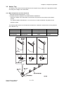
- Since various types of screws are used, ensure that the right screws are used in their right positions.
Use special caution not to confuse the screws for plastic and the ones for sheet metal, because
using the wrong type of screw may result in damage to the screw threads or other troubles.
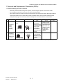
No.
1
2
Type
• Screw for
plastic
• Silver,
flanged,
tapping
• Screw for
metal sheet
• Silver, with
a flange
Application
Shape
Plastic
Coarse
Parts etc Plastic
Sheet metal
How to DistinPoints to Be
guish
Noted
• Silver-colored.
• Oblique screw• With flange.
ing damages the
• Screw thread is
thread because
coarser than that
this screw cuts
of the sheet
female threads
metal type.
in the base
• The thread is
material as it
tapered toward
rotates.
the tip.
Major
Location
• Silver-colored
• It has a flange.
• Diameter of the
thread section is
uniform.
- Wear a wristband or the like wherever possible to remove electrostatic buildup from your body.
Finisher Service Manual
Version 1 2009.03.31
3-1
Chapter 3 Removal and Replacement Procedures (RRPs)
1.2 General Notes
- The string "(PL X.Y.Z)" appended to the part name in the procedure denotes that the part correto the
plate (PL) "X.Y", item "Z" of the Engineering Parts list, and its shape and fitting position can be
checked in the Engineering Parts list.
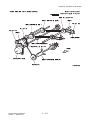
- Directional descriptions used in the procedures are defined as follows:
-Front
: Direction toward you when facing the front of the printer.
-Rear
: Direction opposite to the front when facing the front of the printer.
-Left
: Left-hand direction when facing the front of the printer.
-Right
: Right-hand direction when facing the front of the printer.
Tbt03500KB
Fig.: Directions Regarding the Printer
- The string "(RRP X.Y)" that appears in or at the end of the procedure denotes that the related service procedure is described in [RRP X.Y].
- Unless otherwise specified, use a Phillips-head screwdriver to remove the screws shown in the illus.
- Black arrows shown in the illustrations denote moving directions. The numbers assigned to these
arrows refer to the order in the procedure.
- Refer to [Chapter 4 Plug/Jack (P/J) Connector Locations] for the positions of connectors (P/J).
Finisher Service Manual
Version 2 2009.06.10
3-2
Chapter 3 Removal and Replacement Procedures (RRPs)
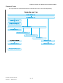
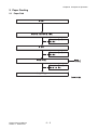
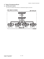
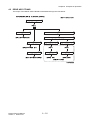
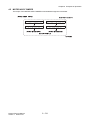
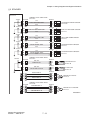
Removal Flows
The components not connected with arrows in the flow below can be removed independently.
"!"123 4
'
,%
-
./
-
0
)
%$
%
(
% *
%
+
!"!# $
%$
$& $
'
Finisher Service Manual
Version 3 2009.07.03
3-3
Chapter 3 Removal and Replacement Procedures (RRPs)
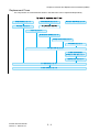
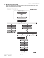
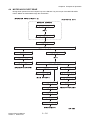
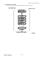
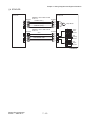
Replacement Flows
The components not connected with arrows in the flow below can be replaced independently.
$$#34 "5
! '&
&( "#$% &
&
)
'
)
' !
'&
'
! *
+
2
-'
.
/0
.
1
! ,
Finisher Service Manual
Version 3 2009.07.03
3-4
Chapter 3 Removal and Replacement Procedures (RRPs)
Blank Page
Finisher Service Manual
Version 1 2009.03.31
3-5
Chapter 3 Removal and Replacement Procedures (RRPs)
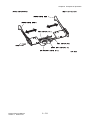
2. Removal Steps
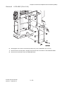
Removal 1
KIT TRAY STACKER (PL14.1.98)
When performing the following step, use caution not to damage the GUIDE TAMPERs.
1)
Remove the TRAY STACKER (PL14.1.2) from the FINISHER ASSY by releasing the two hooks of
the TRAY STACKER.
Go to the next removal step:
Removal 2 KIT FINISHER ASSY (PL14.1.99)
Finisher Service Manual
Version 3 2009.07.03
3-6
Chapter 3 Removal and Replacement Procedures (RRPs)
Blank Page
Finisher Service Manual
Version 1 2009.03.31
3-7
Chapter 3 Removal and Replacement Procedures (RRPs)
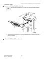
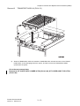
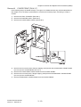
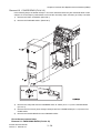
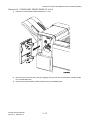
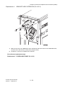
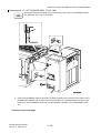
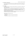
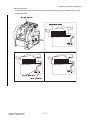
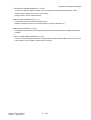
Removal 2
KIT FINISHER ASSY (PL14.1.99)
In the following steps, the details of Step 1 are omitted because they are described earlier in this chapter.
Go to the step in parentheses to execute the necessary steps, and then go to Step 2 onward.
1)
Remove the TRAY STACKER. (Removal 1)
2)-2
2)-1
2)-2
Tbt03537KA
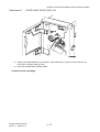
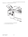
2)
Disengage the AC OUTLET of the CABLE ASSY POWER A4FIN (PL14.11.8) from the printer, and
then release the CABLE ASSY POWER A4FIN from the harness guide on the printer.
Continues to the next page.
Finisher Service Manual
Version 3 2009.07.03
3-8
Chapter 3 Removal and Replacement Procedures (RRPs)
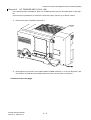
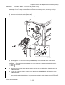
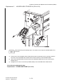
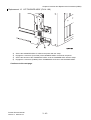
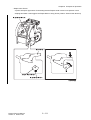
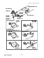
Removal 2
KIT FINISHER ASSY (PL14.1.99)
3)-2
3)-1
4)-2
4)-1
Tbt03502KB
3)
Remove the COVER CONNECTOR (PL14.1.5) from the FINISHER ASSY by releasing the hook of
the COVER CONNECTOR.
4)
Remove the COVER CONNECTOR2 (PL14.1.4) from the FINISHER ASSY by releasing the hook
of the COVER CONNECTOR2.
Continues to the next page.
Finisher Service Manual
Version 3 2009.07.03
3-9
Chapter 3 Removal and Replacement Procedures (RRPs)
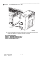
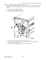
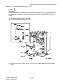
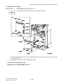
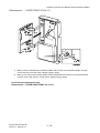
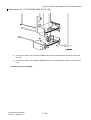
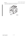
Removal 2
KIT FINISHER ASSY (PL14.1.99)
6)-1
6)-1
6)-2
5)
8)-1
8)-2
7)
8)-1
5)
Tbt03503KB
Disengage the connectors (P/J8987) of the TRANSPORT ASSY A4 (PL14.2.1) from the FINISHER ASSY.
6)
Remove the clamp that fixes the harness of the TRANSPORT ASSY A4 to the FINISHER ASSY.
7)
Disengage the connectors (P121/CN4) of the HARNESS ASSY IF A4FIN (PL14.11.7) from the
8)
Remove the clamp that fixes the HARNESS ASSY IF A4FIN to the printer.
printer.
Continues to the next page.
Finisher Service Manual
Version 3 2009.07.03
3 - 10
Chapter 3 Removal and Replacement Procedures (RRPs)
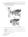
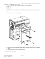
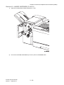
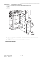
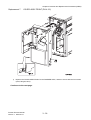
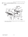
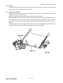
Removal 2
KIT FINISHER ASSY (PL14.1.99)
9)
Tbt03504KB
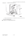
9)
Remove the FINISHER from the printer by lifting it slightly with one hand on the bottom of the
COVER ASSY FRONT (PL 14.3.5) and the other hand on the handle.
Go to the next removal step:
Removal 3 TRANSPORT ASSY A4 (PL14.2.1),
Removal 5 COVER ASSY FRONT (PL14.3.5),
Removal 10 COVER REAR (PL14.3.3)
Finisher Service Manual
Version 3 2009.07.03
3 - 11
Chapter 3 Removal and Replacement Procedures (RRPs)
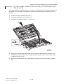
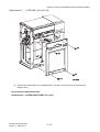
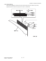
Removal 3
TRANSPORT ASSY A4 (PL14.2.1)
In the following steps, the details of Steps 1 and 2 are omitted because they are described earlier in this
chapter. Go to the steps in parentheses to execute the necessary steps, and then go to Step 3 onward.
1)
Remove the TRAY STACKER. (Removal 1)
2)
Remove the FINISHER ASSY. (Removal 2)
3)-1
3)-1
3)-2
4)
4)
5)
Tbt03505KB
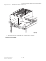
3)
Remove the one clamp that fixes the harness of the TRANSPORT ASSY A4 (PL14.2.1) to the
printer.
When performing the following step, use caution not to drop the BRACKET ASSY GUIDE
ADD.
4)
Remove the two SCREW M4 STEELs (PL14.1.8) while holding the BRACKET ASSY GUIDE ADD
5)
Remove the BRACKET ASSY GUIDE ADD.
(PL14.1.9).
Continues to the next page.
Finisher Service Manual
Version 2 2009.06.10
3 - 12
Chapter 3 Removal and Replacement Procedures (RRPs)
Removal 3
TRANSPORT ASSY A4 (PL14.2.1)
6)
Tbt03506KB
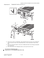
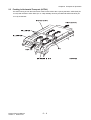
6)
Slide the TRANSPORT ASSY A4 toward the FINISHER ASSY until the two tabs on the TRANSPORT ASSY A4 are disengaged from the printer, and then remove the TRANSPORT ASSY
upward from the printer.
Go to the next removal step:
Removal 4 KIT CHUTE ASSY LOWER H-TRA (PL14.2.98), KIT COVER ASSY TOP H-TRA
(PL14.2.99)
Finisher Service Manual
Version 3 2009.07.03
3 - 13
Chapter 3 Removal and Replacement Procedures (RRPs)
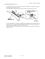
Removal 4
KIT CHUTE ASSY LOWER H-TRA (PL14.2.98), KIT COVER ASSY TOP HTRA (PL14.2.99)
In the following steps, the details of Steps 1 through 3 are omitted because they are described earlier in
this chapter. Go to the steps in parentheses to execute the necessary steps, and then go to Step 4
onward.
1)
Remove the TRAY STACKER. (Removal 1)
2)
Remove the FINISHER ASSY. (Removal 2)
3)
Remove the TRANSPORT ASSY A4. (Removal 3)
5)
4)-1
4)-2
Tbt03507KB
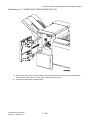
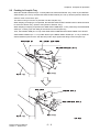
4)
Swing up the COVER ASSY TOP H-TRA (PL14.2.3) until the flat surfaces on the pivots of the
COVER ASSY TOP H-TRA becomes parallel with the U-shaped notches on the CHUTE ASSY
LOWER H-TRA (PL14.2.10).
5)
Remove the COVER ASSY TOP H-TRA diagonally upward from the CHUTE ASSY LOWER HTRA.
Finisher Service Manual
Version 3 2009.07.03
3 - 14
Chapter 3 Removal and Replacement Procedures (RRPs)
Blank Page
Finisher Service Manual
Version 1 2009.03.31
3 - 15
Chapter 3 Removal and Replacement Procedures (RRPs)
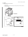
Removal 5
COVER ASSY FRONT (PL14.3.5)
In the following steps, the details of Steps 1 and 2 are omitted because they are described earlier in this
chapter. Go to the steps in parentheses to execute the necessary steps, and then go to Step 3 onward.
1)
Remove the TRAY STACKER. (Removal 1)
2)
Remove the FINISHER ASSY. (Removal 2)
3)-1
3)-1
3)-2
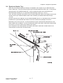
3)
Tbt03508KB
Remove the COVER GUIDE TRAY (PL14.1.3) from FINISHER ASSY by releasing the two hooks
on the COVER GUIDE TRAY.
Continues to the next page.
Finisher Service Manual
Version 2 2009.06.10
3 - 16
Chapter 3 Removal and Replacement Procedures (RRPs)
Removal 5
COVER ASSY FRONT (PL14.3.5)
5)-1
5)-2
Tbt03509KA
4)
Open the COVER ASSY FRONT DOOR (PL14.3.6).
5)
Remove the KNOB ASSY EXIT from the ROLL ASSY DRIVE EXIT (PL14.7.12) by removing the
one screw (sliver, flanged, tapping, 6mm).
Continues to the next page.
Finisher Service Manual
Version 1 2009.03.31
3 - 17
Chapter 3 Removal and Replacement Procedures (RRPs)
Removal 5
COVER ASSY FRONT (PL14.3.5)
6)-2
6)-1
6)-1
6)-1
6)-1
6)
Tbt03510KA
Remove the COVER ASSY FRONT from the FINISHER ASSY by removing the four screws (silver,
flanged, 8mm).
Go to the next removal step:
Removal 6 COVER FRONT (PL14.3.7),
Removal 7 HOLDER ASSY STAPLER A4 (PL14.8.19),
Removal 8 BRACKET ASSY INTERLOCK (PL14.10.1),
Removal 9 LVPS ASSY (PL14.10.10)
Finisher Service Manual
Version 1 2009.03.31
3 - 18
Chapter 3 Removal and Replacement Procedures (RRPs)
Removal 6
COVER FRONT (PL14.3.7)
In the following steps, the details of Steps 1 through 3 are omitted because they are described earlier in
this chapter. Go to the steps in parentheses to execute the necessary steps, and then go to Step 4
onward.
1)
Remove the TRAY STACKER. (Removal 1)
2)
Remove the FINISHER ASSY. (Removal 2)
3)
Remove the COVER ASSY FRONT. (Removal 5)
4)
4)
5)
4)
4)
7)
6)
Tbt03511KA
4)
Remove the four screws (silver, flanged, tapping, 8mm) that fix the COVER ASSY FRONT DOOR
5)
Remove the COVER ASSY FRONT DOOR from the COVER FRONT.
6)
Remove the one screw (silver, flanged, tapping, 8mm) that fixes the BRACKET COVER FRONT
(PL14.3.6) to the COVER FRONT (PL14.3.7).
(PL14.3.8) to the COVER FRONT.
7)
Remove the BRACKET COVER FRONT from the COVER FRONT.
Finisher Service Manual
Version 2 2009.06.10
3 - 19
Chapter 3 Removal and Replacement Procedures (RRPs)
Removal 7
HOLDER ASSY STAPLER A4 (PL14.8.19)
In the following steps, the details of Steps 1 through 3 are omitted because they are described earlier in
this chapter. Go to the steps in parentheses to execute the necessary steps, and then go to Step 4
onward.
1)
Remove the TRAY STACKER. (Removal 1)
2)
Remove the FINISHER ASSY. (Removal 2)
3)
Remove the COVER ASSY FRONT. (Removal 5)
5)
6)
4)
7)
Tbt03512KB
4)
Disengage the two sets of connectors (P/J8886, 8887) of the HOLDER ASSY STAPLER A4
(PL14.8.19).
When performing the following step, use caution not to drop the HOLDER ASSY STAPLER A4.
5)
Remove the one screw (silver, flanged, 6mm) that fixes the HOLDER ASSY STAPLER A4 to the
FINISHER ASSY.
6)
Loosen the one screw (silver, flanged, 6mm) that fixes the HOLDER ASSY STAPLER A4 to the
FINISHER ASSY.
7)
Release the notch of the HOLDER ASSY STAPLER A4 from the loosened screws by slightly lifting
the HOLDER ASSY STAPLER A4. Then, remove the HOLDER ASSY STAPLER A4 from the FINISHER ASSY.
Finisher Service Manual
Version 3 2009.07.03
3 - 20
Chapter 3 Removal and Replacement Procedures (RRPs)
Removal 8
BRACKET ASSY INTERLOCK (PL14.10.1)
In the following steps, the details of Steps 1 through 3 are omitted because they are described earlier in
this chapter. Go to the steps in parentheses to execute the necessary steps, and then go to Step 4
onward.
1)
Remove the TRAY STACKER. (Removal 1)
2)
Remove the FINISHER ASSY. (Removal 2)
3)
Remove the COVER ASSY FRONT. (Removal 5)
6)
5)
5)
4)
Tbt03513KA
4)
Disengage the connectors (P/J8889) of the SWITCH (PL14.10.13).
5)
Remove the two screws (silver, flanged, 6mm) that fix the BRACKET ASSY INTERLOCK
(PL14.10.1) to the FINISHER ASSY.
6)
Remove the BRACKET ASSY INTERLOCK from the FINISHER ASSY.
Finisher Service Manual
Version 1 2009.03.31
3 - 21
Chapter 3 Removal and Replacement Procedures (RRPs)
Removal 9
LVPS ASSY (PL14.10.10)
Use a wrist strap to protect the PWB from electrostatic damage.
In the following steps, the details of Steps 1 through 3 are omitted because they are described earlier in
this chapter. Go to the steps in parentheses to execute the necessary steps, and then go to Step 4
onward.
1)
Remove the TRAY STACKER. (Removal 1)
2)
Remove the FINISHER ASSY. (Removal 2)
3)
Remove the COVER ASSY FRONT. (Removal 5)
4)
4)
5)
4)
4)
Tbt03514KA
4)
Remove the four screws (silver, flanged, 8mm) that fix the COVER RH (PL14.3.4) to the FINISHER
5)
Remove the COVER RH from the FINISHER ASSY.
ASSY.
Continues to the next page.
Finisher Service Manual
Version 1 2009.03.31
3 - 22
Chapter 3 Removal and Replacement Procedures (RRPs)
Removal 9
LVPS ASSY (PL14.10.10)
8)
6)
7)
7)
7)
6)
7)
7)
Tbt03515KB
6)
Disengage the two sets of connectors (P/J590, 591) of the LVPS ASSY (PL14.10.10).
7)
Remove the five screws (silver, flanged, 6mm) that fix the LVPS ASSY to the FINISHER ASSY.
8)
Remove the LVPS ASSY from the FINISHER ASSY.
Finisher Service Manual
Version 2 2009.06.10
3 - 23
Chapter 3 Removal and Replacement Procedures (RRPs)
Removal 10 COVER REAR (PL14.3.3)
In the following steps, the details of Steps 1 and 2 are omitted because they are described earlier in this
chapter. Go to the steps in parentheses to execute the necessary steps, and then go to Step 3 onward.
1)
Remove the TRAY STACKER. (Removal 1)
2)
Remove the FINISHER ASSY. (Removal 2)
4)
4)
5)
4)
4)
3)-1
3)-1
3)-2
Tbt03516KB
3)
Remove the clamp that fixes the HARNESS ASSY IF A4FIN (PL14.11.7) to the COVER REAR
(PL14.3.3).
4)
Remove the four screws (silver, flanged, 8mm) that fix the COVER REAR (PL14.3.3) to the FINISHER ASSY.
5)
Remove the COVER REAR from the FINISHER ASSY.
Go to the next removal step:
Removal 11 PWBA MAIN A4FIN (PL14.4.12)
Finisher Service Manual
Version 2 2009.06.10
3 - 24
Chapter 3 Removal and Replacement Procedures (RRPs)
Removal 11 PWBA MAIN A4FIN (PL14.4.12)
Use a wrist strap to protect the PWB from electrostatic damage.
In the following steps, the details of Steps 1 through 3 are omitted because they are described earlier in
this chapter. Go to the steps in parentheses to execute the necessary steps, and then go to Step 4
onward.
1)
Remove the TRAY STACKER. (Removal 1)
2)
Remove the FINISHER ASSY. (Removal 2)
3)
Remove the COVER REAR. (Removal 10)
4)
(P8987)
(P8988)
(P8989)
(P8986)
(P8983)
(P8984)
(P8980)
(P8990)
(P8982)
(P8373)
5)
5)
6)
5)
5)
5)
Tbt03517KA
4)
Disengage all the connectors of the PWBA MAIN A4FIN (PL14.4.12).
5)
Remove the five screws (silver, flanged, 6mm) that fix the PWBA MAIN A4FIN to the FINISHER
6)
Remove the PWBA MAIN A4FIN from the FINISHER ASSY.
ASSY.
Finisher Service Manual
Version 1 2009.03.31
3 - 25
Chapter 3 Removal and Replacement Procedures (RRPs)
Removal 12 HOLDER CARTRIDGE (PL14.8.21)
1)
Open the COVER ASSY FRONT DOOR (PL14.3.6).
2)
Tbt03518KA
2)
Pull out the HOLDER CARTRIDGE (PL14.8.21) from the FINISHER ASSY.
Finisher Service Manual
Version 1 2009.03.31
3 - 26
Chapter 3 Removal and Replacement Procedures (RRPs)
Removal 13 COVER ASSY FRONT DOOR (PL14.3.6)
1)
Open the COVER ASSY FRONT DOOR (PL14.3.6).
2)
2)
2)
3)
2)
Tbt03538KA
2)
Remove the four screws (silver, flanged, tapping, 8mm) that fix the COVER ASSY FRONT DOOR
to the FINISHER ASSY.
3)
Remove the COVER ASSY FRONT DOOR from the FINISHER ASSY.
Finisher Service Manual
Version 2 2009.06.10
3 - 27
Chapter 3 Removal and Replacement Procedures (RRPs)
4. Replacement Steps
Replacement 1
PWBA MAIN A4FIN (PL14.4.12)
Use a wrist strap to protect the PWB from electrostatic damage.
2)
(P8987)
(P8988)
(P8989)
(P8986)
(P8983)
(P8984)
(P8980)
(P8990)
(P8982)
(P8373)
1)-1
1)-2
1)-2
1)-2
1)-2
1)-2
1)
Tbt03519KA
Replace the PWBA MAIN A4FIN to the FINISHER ASSY, and then secure with the five screws (silver, flanged, 6mm).
2)
Engage all the connectors of the PWBA MAIN A4FIN.
Go to the next replacement step:
Replacement 2 COVER REAR (PL14.3.3)
Finisher Service Manual
Version 1 2009.03.31
3 - 28
Chapter 3 Removal and Replacement Procedures (RRPs)
Replacement 2
COVER REAR (PL14.3.3)
1)-1
1)-2
1)-2
1)-2
1)-2
2)
Tbt03520KB
1)
Replace the COVER REAR to the FINISHER ASSY, and then secure with the four screws (silver,
flanged, 8mm).
2)
Secure the HARNESS ASSY IF A4FIN to the COVER REAR with the clamp.
Go to the next replacement step:
Replacement 10 KIT FINISHER ASSY (PL14.1.99)
Finisher Service Manual
Version 3 2009.07.03
3 - 29
Chapter 3 Removal and Replacement Procedures (RRPs)
Replacement 3
LVPS ASSY (PL14.10.10)
Use a wrist strap to protect the PWB from electrostatic damage.
2)
1)
1)
1)
2)
1)
1)
1)
Replace the LVPS ASSY to the FINISHER ASSY, and then secure with the five screws (silver,
flanged, 6mm).
2)
Tbt03521KB
Engage the two sets of connectors (P/J590, 591) of the LVPS ASSY.
Continues to the next page.
Finisher Service Manual
Version 2 2009.06.10
3 - 30
Chapter 3 Removal and Replacement Procedures (RRPs)
Replacement 3
LVPS ASSY (PL14.10.10)
3)-1
3)-2
3)-2
3)-2
3)-2
3)
Tbt03522KA
Replace the COVER RH to the FINISHER ASSY, and then secure with the four screws (silver,
flanged, 8mm).
Go to the next replacement step:
Replacement 7 COVER ASSY FRONT (PL14.3.5)
Finisher Service Manual
Version 1 2009.03.31
3 - 31
Chapter 3 Removal and Replacement Procedures (RRPs)
Replacement 4
BRACKET ASSY INTERLOCK (PL14.10.1)
1)-1
1)-2
1)-2
2)
Tbt03523KA
1)
Mate the two holes of the BRACKET ASSY INTERLOCK with the bosses of the FINISHER ASSY,
2)
Engage the connectors (P/J8889) of the SWITCH.
and then secure with the two screws (silver, flanged, 6mm).
Go to the next replacement step:
Replacement 7 COVER ASSY FRONT (PL14.3.5)
Finisher Service Manual
Version 1 2009.03.31
3 - 32
Chapter 3 Removal and Replacement Procedures (RRPs)
Replacement 5
HOLDER ASSY STAPLER A4 (PL14.8.19)
2)
1)
3)
2)
Tbt03524KB
When performing the following steps, use caution not to drop the HOLDER ASSY STAPLER A4.
1)
Fit the notch of the HOLDER ASSY STAPLER A4 with the loosened screws, and then mate the
two holes of the HOLDER ASSY STAPLER A4 with the bosses of the FINISHER ASSY.
2)
Secure the HOLDER ASSY STAPLER A4 to the FINISHER ASSY with the two screws (silver,
flanged, 6mm).
3)
Engage the two sets of connectors (P/J8886, 8887) of the HOLDER ASSY STAPLER A4.
Go to the next replacement step:
Replacement 7 COVER ASSY FRONT (PL14.3.5)
Finisher Service Manual
Version 3 2009.07.03
3 - 33
Chapter 3 Removal and Replacement Procedures (RRPs)
Replacement 6
COVER FRONT (PL14.3.7)
2)-2
2)-2
2)-1
2)-2
2)-2
1)-1
1)-2
Tbt03525KA
1)
Mate the hole of the BRACKET COVER FRONT with the boss of the COVER FRONT, and then
secure with the one screw (silver, flanged, tapping, 8mm).
2)
Mate the four holes of the COVER ASSY FRONT DOOR with the bosses of the COVER FRONT,
and then secure with the four screws (silver, flanged, tapping, 8mm).
Go to the next replacement step:
Replacement 7 COVER ASSY FRONT (PL14.3.5)
Finisher Service Manual
Version 2 2009.06.10
3 - 34
Chapter 3 Removal and Replacement Procedures (RRPs)
Blank Page
Finisher Service Manual
Version 1 2009.03.31
3 - 35
Chapter 3 Removal and Replacement Procedures (RRPs)
Replacement 7
COVER ASSY FRONT (PL14.3.5)
1)-1
1)-2
1)-2
1)-2
1)-2
1)
Tbt03526KA
Replace the COVER ASSY FRONT to the FINISHER ASSY, and then secure with the four screws
(silver, flanged, 8mm).
Continues to the next page.
Finisher Service Manual
Version 1 2009.03.31
3 - 36
Chapter 3 Removal and Replacement Procedures (RRPs)
Replacement 7
COVER ASSY FRONT (PL14.3.5)
2)-2
2)-1
Tbt03527KA
2)
Replace the KNOB ASSY EXIT to the ROLL ASSY DRIVE EXIT, and then secure with the one
3)
Close the COVER ASSY FRONT DOOR.
screw (sliver, flanged, tapping, 6mm).
Continues to the next page.
Finisher Service Manual
Version 1 2009.03.31
3 - 37
Chapter 3 Removal and Replacement Procedures (RRPs)
Replacement 7
COVER ASSY FRONT (PL14.3.5)
4)-2
4)-1
Tbt03528KB
4)
Replace the COVER GUIDE TRAY to the FINISHER ASSY, and then secure with the two hooks.
Go to the next replacement step:
Replacement 10 KIT FINISHER ASSY (PL14.1.99)
Finisher Service Manual
Version 3 2009.07.03
3 - 38
Chapter 3 Removal and Replacement Procedures (RRPs)
Replacement 8
KIT CHUTE ASSY LOWER H-TRA (PL14.2.98), KIT COVER ASSY
TOP H-TRA (PL14.2.99)
2)
1)
Tbt03529KB
1)
Mate the pivots of the COVER ASSY TOP H-TRA into the U-shaped notches on the CHUTE ASSY
2)
Swing down the COVER ASSY TOP H-TRA.
LOWER H-TRA so that the flat surfaces of the pivots become parallel with the notches.
Go to the next replacement step:
Replacement 9 TRANSPORT ASSY A4 (PL14.2.1)
Finisher Service Manual
Version 3 2009.07.03
3 - 39
Chapter 3 Removal and Replacement Procedures (RRPs)
Replacement 9
TRANSPORT ASSY A4 (PL14.2.1)
1)
Tbt03530KB
1)
Mate the two tabs on the TRANSPORT ASSY A4 with the holes on the printer.
Continues to the next page.
Finisher Service Manual
Version 2 2009.06.10
3 - 40
Chapter 3 Removal and Replacement Procedures (RRPs)
Replacement 9
TRANSPORT ASSY A4 (PL14.2.1)
2)
4)
3)
3)
Tbt03531KB
2)
Align the two notches on the BRACKET ASSY GUIDE ADD with the bosses on the TRANSPORT
ASSY A4 and let the hooks of the TRANSPORT ASSY A4 catch the BRACKET ASSY GUIDE
ADD.
3)
Secure the TRANSPORT ASSY A4 with the two SCREW M4 STEELs while holding the BRACKET
ASSY GUIDE ADD.
4)
Secure the harness of the TRANSPORT ASSY A4 to the printer with the clamp.
Go to the next replacement step:
Replacement 10 KIT FINISHER ASSY (PL14.1.99)
Finisher Service Manual
Version 3 2009.07.03
3 - 41
Chapter 3 Removal and Replacement Procedures (RRPs)
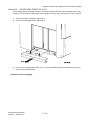
Replacement 10 KIT FINISHER ASSY (PL14.1.99)
When performing the following step, ensure that the two studs on the FINISHER ASSY
are mated with the holes on the printer.
1)
Tbt03532KB
1)
Replace the FINISHER ASSY to the printer by lifting it slightly with one hand on the bottom of the
COVER ASSY FRONT and the other hand on the handle on the COVER REAR so that the righthand notch on the FINISHER ASSY fits onto the BRACKET GUIDE on the TRANSPORT ASSY
A4.
Continues to the next page.
Finisher Service Manual
Version 3 2009.07.03
3 - 42
Chapter 3 Removal and Replacement Procedures (RRPs)
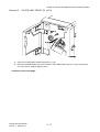
Replacement 10 KIT FINISHER ASSY (PL14.1.99)
4)
5)
3)
2)
Tbt03533KB
2)
Secure the HARNESS ASSY IF A4FIN to the printer with the clamp.
3)
Engage the connectors (P121/CN4) of the HARNESS ASSY IF A4FIN to the printer.
4)
Secure the harness of the TRANSPORT ASSY A4 to the FINISHER ASSY with the clamp.
5)
Engage the connectors (P/J8987) of the TRANSPORT ASSY A4 to the FINISHER ASSY.
Continues to the next page.
Finisher Service Manual
Version 3 2009.07.03
3 - 43
Chapter 3 Removal and Replacement Procedures (RRPs)
Replacement 10 KIT FINISHER ASSY (PL14.1.99)
7)-1
7)-2
6)-1
6)-2
Tbt03534KB
6)
Insert the two tabs on the COVER CONNECTOR2 into the COVER REAR, and then secure with
the hook.
7)
Insert the two tabs on the COVER CONNECTOR into the COVER REAR, and then secure with the
hook.
Continues to the next page.
Finisher Service Manual
Version 3 2009.07.03
3 - 44
Chapter 3 Removal and Replacement Procedures (RRPs)
Replacement 10 KIT FINISHER ASSY (PL14.1.99)
8)-2
8)-1
8)-2
Tbt03539KA
8)
Engage the AC OUTLET of the CABLE ASSY POWER A4FIN to the printer, and then route the
CABLE ASSY POWER A4FIN along the harness guide of the printer.
Go to the next replacement step:
Replacement 11 KIT TRAY STACKER (PL14.1.98)
Finisher Service Manual
Version 3 2009.07.03
3 - 45
Chapter 3 Removal and Replacement Procedures (RRPs)
Replacement 11 KIT TRAY STACKER (PL14.1.98)
When performing the following step, use caution not to damage the GUIDE TAMPERs.
1)
Replace the TRAY STACKER to the CARRIAGE ASSY (PL14.9.16) on the FINISHER ASSY, and
then secure with the two hooks.
Finisher Service Manual
Version 3 2009.07.03
3 - 46
Chapter 3 Removal and Replacement Procedures (RRPs)
Replacement 12 HOLDER CARTRIDGE (PL14.8.21)
1)
Tbt03536KA
1)
Insert the HOLDER CARTRIDGE into the FINISHER ASSY.
2)
Close the COVER ASSY FRONT DOOR.
Finisher Service Manual
Version 1 2009.03.31
3 - 47
Chapter 3 Removal and Replacement Procedures (RRPs)
Replacement 13 COVER ASSY FRONT DOOR (PL14.3.6)
1)-2
1)-2
1)-1
1)-2
1)-2
Tbt03540KA
1)
Mate the four holes of the COVER ASSY FRONT DOOR with the bosses of the COVER FRONT,
and then secure with the four screws (silver, flanged, tapping, 8mm).
2)
Close the COVER ASSY FRONT DOOR.
Finisher Service Manual
Version 2 2009.06.10
3 - 48
Chapter 4 Plug/Jack(P/J) Connector Locations
Chapter 4 Plug/Jack(P/J) Connector Locations CONTENTS
1. Connector [P (plug) / J (jack)].....................................................................................4 - 1
1.1 List of P/J ......................................................................................................................................... 4 - 1
1.2 FINISHER P/J layout diagram ......................................................................................................... 4 - 2
Finisher Service Manual
Version 1 2009.03.31
Chapter 4 Plug/Jack(P/J) Connector Locations
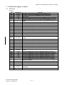
1. Connector [P (plug) / J (jack)]
1.1
List of P/J
Finisher
P/J
590
591
8373
8863
Coordinates
G-126
G-123
I-144
I-108
8864
B-108
8869
8870
8871
8872
8873
8874
8876
8877
8878
8879
E-133
D-135
D-135
E-136
E-135
E-135
D-133
C-134
D-136
C-135
8880
E-122
8881
8882
8883
8884
8885
8886
8887
D-122
G-121
F-122
G-122
E-137
E-124
D-124
8889
G-132
8980
8982
8983
8984
8986
H-143
J-144
J-143
J-143
I-142
8987
H-142
8988
8989
8990
AC
OUTLET
CN4
I-142
I-142
H-144
A-141
A-139
Finisher Service Manual
Version 2 2009.06.10
Remarks
Connects LVPS ASSY and CABLE ASSY POWER A4FIN
Connects LVPS ASSY and HARNESS ASSY LVPS A4FIN
Not Connect
Connects MOTOR ASSY PM HTU and HARNESS ASSY HTU A4FIN
Connects H-TRA Top Cover Open Sensor and HARNESS ASSY HTU
A4FIN
Connects Compile Exit Sensor and HARNESS ASSY SNR2 A4FIN
Connects Eject Clamp Home Sensor and HARNESS ASSY SNR2 A4FIN
Connects Set Clamp Home Sensor and HARNESS ASSY SNR2 A4FIN
Connects Stacker No Paper Sensor and HARNESS ASSY SNR2 A4FIN
Connects Stack Height Sensor1 and HARNESS ASSY SNR2 A4FIN
Connects Stack Height Sensor2 and HARNESS ASSY SNR2 A4FIN
Connects Sub Paddle Solenoid and HARNESS ASSY MOT2 A4FIN
Connects Set Clamp Clutch and HARNESS ASSY MOT2 A4FIN
Connects Eject Motor and HARNESS ASSY MOT2 A4FIN
Connects Transport Motor and HARNESS ASSY MOT2 A4FIN
Connects Compile Tray No Paper Sensor and HARNESS ASSY SNR1
A4FIN
Connects Front Tamper Home Sensor and HARNESS ASSY SNR1 A4FIN
Connects Rear Tamper Home Sensor and HARNESS ASSY SNR1 A4FIN
Connects Rear Tamper Motor and HARNESS ASSY MOT1 A4FIN
Connects Front Tamper Motor and HARNESS ASSY MOT1 A4FIN
Connects Stacker Motor and HARNESS ASSY MOT3 A4FIN
Connects STAPLER ASSY and HARNESS ASSY SNR1 A4FIN
Connects STAPLER ASSY and HARNESS ASSY MOT1 A4FIN
Connects Finisher Front Door Switch and HARNESS ASSY INTL SW
A4FIN
Connects PWBA MAIN A4FIN and HARNESS ASSY LVPS A4FIN
Connects PWBA MAIN A4FIN and HARNESS ASSY INTL SW A4FIN
Connects PWBA MAIN A4FIN and HARNESS ASSY MOT1 A4FIN
Connects PWBA MAIN A4FIN and HARNESS ASSY MOT2 A4FIN
Connects PWBA MAIN A4FIN and HARNESS ASSY MOT3 A4FIN
Connects PWBA MAIN A4FIN and Horizontal Transport (HARNESS
ASSY HTU A4FIN)
Connects PWBA MAIN A4FIN and HARNESS ASSY SNR1 A4FIN
Connects PWBA MAIN A4FIN and HARNESS ASSY SNR2 A4FIN
Connects PWBA MAIN A4FIN and HARNESS ASSY IF A4FIN
Connects CABLE ASSY POWER A4FIN and Printer (HARNESS ASSY
FIN PWR)
Connects HARNESS ASSY IF A4FIN and Printer (HARNESS ASSY FIN)
4–1
Chapter 4 Plug/Jack(P/J) Connector Locations
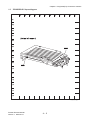
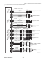
1.2
FINISHER P/J layout diagram
! #$%
Finisher Service Manual
Version 1 2009.03.31
4–2
Chapter 4 Plug/Jack(P/J) Connector Locations
A
B
C
D
E
F
G
H
I
J
K
L
116
117
118
119
120
8882
121
8883
8881
8884
122
8880
123
124
125
591
8887
8886
590
126
127
128
129
130
Tbt04101KB
Finisher Service Manual
Version 2 2009.06.10
4–3
Chapter 4 Plug/Jack(P/J) Connector Locations
Finisher Service Manual
Version 2 2009.06.10
4–4
Chapter 6 Principles of Operation
Chapter 6 Principles of Operation CONTENTS
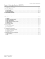
1. Overview......................................................................................................................6 - 1
1.1 Configuration..................................................................................................................................... 6 - 1
2. Paper Feeding .............................................................................................................6 - 2
2.1 Paper Path ........................................................................................................................................ 6 - 2
2.2 Layout of Paper Path ........................................................................................................................ 6 - 3
2.3 Feeding in Horizontal Transport (H-TRA) ......................................................................................... 6 - 4
2.4 Feeding in X' port .............................................................................................................................. 6 - 5
2.5 Feeding in Compile Tray................................................................................................................... 6 - 6
2.6 Ejection to Stacker Tray.................................................................................................................... 6 - 7
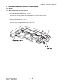
3. Functions of Major Functional Components ................................................................6 - 8
3.1 H-TRA ............................................................................................................................................... 6 - 8
3.1.1 Major Components and Their Functions................................................................................... 6 - 8
3.2 X' port................................................................................................................................................ 6 - 9
3.2.1 Major Components and Their Functions................................................................................... 6 - 9
3.3 Compile Tray................................................................................................................................... 6 - 10
3.3.1 Major Components and Their Functions................................................................................. 6 - 10
3.3.2 Operations in Compile Tray .................................................................................................... 6 - 12
3.3.2.1 Tamping.......................................................................................................................... 6 - 12
3.3.2.2 Offset Stacking ............................................................................................................... 6 - 13
3.3.2.3 Sheet/Envelope Select Lever ......................................................................................... 6 - 14
3.4 Stapler............................................................................................................................................. 6 - 16
3.4.1 Major Components and Their Functions................................................................................. 6 - 16
3.4.2 Stapling ................................................................................................................................... 6 - 21
3.4.2.1 Operation of Stapling ...................................................................................................... 6 - 21
3.4.2.2 Stapling Position ............................................................................................................. 6 - 22
3.5 Stacker Tray.................................................................................................................................... 6 - 23
3.5.1 Major Components and Their Functions................................................................................. 6 - 23
3.6 Electrical ......................................................................................................................................... 6 - 28
3.6.1 Major Components and Their Functions................................................................................. 6 - 28
4. Torque Transmission Route ......................................................................................6 - 30
4.1 MOTOR ASSY PM HTU ................................................................................................................. 6 - 30
4.2 DRIVE ASSY TRANS ..................................................................................................................... 6 - 32
4.3 MOTOR ASSY EJECT DRIVE........................................................................................................ 6 - 34
4.4 MOTOR ASSY EJECT DRIVE........................................................................................................ 6 - 36
4.5 MOTOR ASSY TAMPER ................................................................................................................ 6 - 38
4.6 DRIVE ASSY STACKER ................................................................................................................ 6 - 40
Finisher Service Manual
Version 3 2009.07.03
Chapter 6 Principles of Operation
Chapter 6 Principles of Operation CONTENTS
Finisher Service Manual
Version 3 2009.07.03
Chapter 6 Principles of Operation
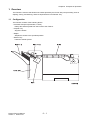
1. Overview
The Finisher is a device that finishes the sheets ejected by the Printer with post-processing such as
stapling, sorting, and stacking, and then deposits them in its Stacker Tray.
1.1 Configuration
The Finisher consists of the following blocks:
- Horizontal Transport (hereinafter, H-TRA)
Relays the sheets ejected from the Printer to the Finisher.
- Compile Tray
Aligns the sheets.
- Stapler
Staples the sheets in the specified position.
- Stacker Tray
Holds the sheets ejected.
Finisher Service Manual
Version 1 2009.03.31
6–1
Chapter 6 Principles of Operation
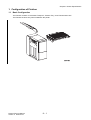
2. Paper Feeding
2.1 Paper Path
!
$" $" !"% "#
&'()')*
Finisher Service Manual
Version 1 2009.03.31
6–2
Chapter 6 Principles of Operation
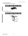
2.2 Layout of Paper Path
' # !(
' # !!!
" " #$ ! %
& # ! Finisher Service Manual
Version 1 2009.03.31
6–3
Chapter 6 Principles of Operation
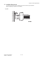
2.3 Feeding in Horizontal Transport (H-TRA)
The sheet coming in from the Exit section of the Printer is fed to the X' port by the ROLL ASSY ENT (PL
14.2.24) and the ROLL ASSY EXIT (PL 14.2.26) rotatably driven by the MOTOR ASSY PM HTU (PL
14.2.16) via the Belt.
'(" (
## $&
## $%
!"
Finisher Service Manual
Version 1 2009.03.31
6–4
Chapter 6 Principles of Operation
2.4 Feeding in X' port
The sheet coming in from the H-TRA is fed to the Compile Tray by the ROLL ASSY DRIVE ENT (PL
14.7.11) and the ROLL ASSY DRIVE EXIT (PL 14.7.12) rotatably driven by the DRIVE ASSY TRANS
(PL 14.7.16) via the Belt.
The passage of the sheet is detected by the COMPILE EXIT SENSOR (PL 14.7.9). (No paper: Sensor
beam blocked. Refer to 3.2.1 Major Components and Their Functions.)
!"# %"
&
!"# $
Finisher Service Manual
Version 2 2009.06.10
!"# $
6–5
Chapter 6 Principles of Operation
2.5 Feeding in Compile Tray
While the GUIDE PAPER 240 (PL 14.5.38) slides out toward the Stacker Tray, driven by the MOTOR
ASSY EJECT (PL 14.5.6), the ROLLER ASSY EJECT PINCH (PL 14.6.3) retracts upward to allow the
sheet to come in from the X' port.
The sheet coming in from the X' port falls onto the Compile Tray.
When stapling or tamping is not specified, the ROLLER ASSY EJECT PINCH lowers to allow the sheet
to exit to the Stacker Tray. (Refer to 2.6 Ejection to Stacker Tray.)
When stapling or tamping is specified, the ARM ASSY PADDLE (PL 14.6.4) lowered by the SOLENOID
ASSY (PL 14.6.20), upon the falling of the sheet onto the Compile Tray.
Then, the PADDLE SUB (PL 14.6.8) of the ARM ASSY PADDLE and the Main Paddle of the SHAFT
ASSY MAIN PADDLE (PL 14.7.13) rotate driven by the DRIVE ASSY TRANS (PL 14.7.6), to slide the
sheet backward (reverse to the exit direction) until it stops against the flange of the Compile Tray.
% & '&(")
#!"
! "#$
#-.!" "#$
,
* #!"
#-.!" "#$
Finisher Service Manual
Version 1 2009.03.31
+ * ! "#$
6–6
Chapter 6 Principles of Operation
2.6 Ejection to Stacker Tray
When the processing as stapling or tamping is completed in the Compile Tray, the ROLLER ASSY
EJECT PINCH (PL 14.6.13) is lowered by the torque of the MOTOR ASSY EJECT (PL 14.5.6) and the
spring pressure of the SPRING PINCH (PL 14.6.2) to guide the sheet to the point between the
ROLLER EJECT PINCH (PL 14.6.16) and the ROLLER ASSY EJECT (PL 14.6.31).
Then, the sheet is ejected to the Stacker Tray by the ROLLER ASSY EJECT that rotates in the normal
direction driven by the MOTOR ASSY EJECT and controlled by the GEAR ASSY SECTOR (PL
14.5.18).
During the ejection to the Stacker Tray, the GUIDE PAPER 240 (PL 14.5.38) slides back to its original
position driven by the MOTOR ASSY EJECT so as not to obstruct the passage of the sheet.
Meanwhile, the CLUTCH Z34 (PL 14.5.25) transmits the torque of the MOTOR ASSY EJECT to the
SHAFT ASSY SET CLAMP (PL 14.6.32), retracting the Holder of the SHAFT ASSY SET CLAMP inside
the Finisher so as not to obstruct the passage of the sheet.
Upon completion of the sheet ejection, the Holder of the SHAFT ASSY SET CLAMP returns to its
original position to hold down the sheet ejected.
!" "#
$!"
Finisher Service Manual
Version 1 2009.03.31
6–7
Chapter 6 Principles of Operation
3. Functions of Major Functional Components
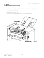
3.1 H-TRA
3.1.1 Major Components and Their Functions
- HTU H-XPORT OPEN SENSOR (PL 14.2.36)
A sensor for detecting whether the COVER ASSY TOP of the H-TRA is open.
(COVER open: Sensor beam received)
- MOTOR ASSY PM HTU (PL 14.2.14)
A motor that drives the belt for paper feeding in the H-TRA. It is provided with the FAN A3
(PL14.2.15) for cooling down the motor in the H-Tra.
Finisher Service Manual
Version 2 2009.06.10
6–8
Chapter 6 Principles of Operation
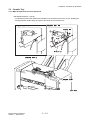
3.2 X' port
3.2.1 Major Components and Their Functions
- COMPILE EXIT SENSOR (PL 14.7.9)
A sensor for detecting the presence of the paper in the X' port based on the change of its actuator
position.
(No paper: Sensor beam blocked)
- DRIVE ASSY TRANS (PL 14.7.16)
A motor that drives all feeding-related rollers in the X' port and Compile Tray.
Finisher Service Manual
Version 2 2009.06.10
6–9
Chapter 6 Principles of Operation
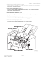
3.3 Compile Tray
3.3.1 Major Components and Their Functions
- SOLENOID ASSY (PL 14.6.20)
A solenoid that lowers the ARM ASSY PADDLE onto the sheet fed from the X' port, allowing the
rotating PADDLE SUB to align the sheet to the flange of the Compile Tray.
!" #
Finisher Service Manual
Version 1 2009.03.31
6 – 10
Chapter 6 Principles of Operation
- COMPILE TRAY NO PAPER SENSOR (PL 14.8.13)
Detects the presence of the paper in the Compile Tray based on the change of its actuator position.
(Paper present: Sensor beam received)
- FRONT TAMPER HOME SENSOR (PL 14.8.9)
A sensor for detecting that the GUIDE TAMPER FRONT A4 (PL 14.8.4) is at its home position.
(Home position: Sensor beam blocked).
- REAR TAMPER HOME SENSOR (PL 14.8.9)
A sensor for detecting that the GUIDE TAMPER REAR A4 (PL 14.8.5) is at its home position.
(Home position: Sensor beam blocked)
- MOTOR ASSY TAMPER (FRONT) (PL 14.8.18)
A motor that moves the GUIDE TAMPER FRONT A4 for tamping operation.
- MOTOR ASSY TAMPER (REAR) (PL 14.8.18)
A motor that moves the GUIDE TAMPER REAR A4 for tamping operation.
!
!
Finisher Service Manual
Version 2 2009.06.10
6 – 11
Chapter 6 Principles of Operation
3.3.2 Operations in Compile Tray
In the Compile Tray, the sheets fed from the X' port undergo the tamping operation for alignment with
respect to width direction, and the offset stacking operation for placing the sets of sheets staggered in
the Stacker Tray.
3.3.2.1 Tamping
The sheets fed from the X' port undergo the tamping operation in the Compile Tray for alignment with
respect to width direction.
Tamping refers to the operation of aligning the sheet to the specified position by sliding the GUIDE
TAMPER FRONT A4 (PL 14.8.4) and the GUIDE TAMPER REAR A4 (PL 14.8.5) until they contact the
sheet edges by the torque from the respective motors (MOTOR ASSY TAMPER: PL 14.8.18).
This operation is executed when the specified time has elapsed after the trail edge of the sheet passed
through the Compile Exit Sensor (PL14.7.9).
A tamping is executed for each incoming sheet. When stapling is specified, an additional tamping is
executed after the tamping for the last sheet is completed.
Tamping includes the following two modes:
- Front Tamping
Activates the Rear Tamper only, with the Front Tamper locked.
- Rear Tamping
Activates the Front Tamper only, with the Rear Tamper locked.
Finisher Service Manual
Version 2 2009.06.10
6 – 12
Chapter 6 Principles of Operation
3.3.2.2 Offset Stacking
Offset stacking staggers the position where the ejected sheets land on the Stacker Tray to help
separate the stack of sheets into groups such as jobs or collated sets.
Finisher Service Manual
Version 1 2009.03.31
6 – 13
Chapter 6 Principles of Operation
3.3.2.3 Sheet/Envelope Select Lever
The Sheet/Envelope Select Lever can be switched to the "Sheet Mode" or "Envelope Mode" position
depending on the print media to be used.
In the "Sheet Mode", the sheet exits to the Stacker Tray without contacting the Select Lever.
!
"##
In the "Envelope Mode", the envelope is corrugated along the feeding direction by the projection from
the Select Lever. This corrugation increases the rigidity of the envelope, thereby preventing the lead
edge from slipping underneath the flap of the previous envelope.
Meanwhile, the Stacker Tray lowers slightly from the normal position to ensure that the envelopes are
stacked up neatly.
Finisher Service Manual
Version 2 2009.06.10
6 – 14
Chapter 6 Principles of Operation
!""
!""
Finisher Service Manual
Version 2 2009.06.10
6 – 15
Chapter 6 Principles of Operation
3.4 Stapler
3.4.1 Major Components and Their Functions
- Low Staple Sensor
A photo-interrupter type sensor for detecting the remaining quantity of the staples. (Staples low:
Sensor beam blocked)
Finisher Service Manual
Version 3 2009.07.03
6 – 16
Chapter 6 Principles of Operation
- Self Priming Sensor
A photo-interrupter type sensor for detecting that the staple has reached the Stapler Head or that
stapling has failed.
! "
!!#$
Finisher Service Manual
Version 3 2009.07.03
6 – 17
Chapter 6 Principles of Operation
- Staple Home Sensor
A photo-interrupter type sensor for detecting that the Stapler Head is at its home position or that
stapling has failed. It also triggers the Staple Motor to stop. (Home position: Sensor beam blocked)
Finisher Service Manual
Version 3 2009.07.03
6 – 18
Chapter 6 Principles of Operation
- Staple Motor
A motor that drives the Stapler Head to execute stapling. Rotates clockwise to activate the Stapler
Head, and counterclockwise to return it to its original position.
Finisher Service Manual
Version 3 2009.07.03
6 – 19
Chapter 6 Principles of Operation
Blank Page
Finisher Service Manual
Version 3 2009.07.03
6 – 20
Chapter 6 Principles of Operation
3.4.2 Stapling
The sheets coming in from the X' port undergo tamping in the Compile Tray, and then are stapled in the
position specified by the Printer. (Up to 50 sheets)
3.4.2.1 Operation of Stapling
Stapling starts when the number of sheets deposited in the Compile Tray has reached the number of
sheets for one set. (Up to 50 sheets)
Stapling is executed by the Stapler Head that comes down to the sheets.
When the Staple Motor rotates in the normal direction (clockwise), the Stapler Head applies a staple
onto the sheets and then returns to its home position. If stapling is not completed correctly, the Staple
Motor rotates in the reverse direction (counterclockwise) to drive the Stapler Head back to its home
position.
When staples are low, the Low Staple Sensor raises a warning message and suspends stapling. This
warning message is also displayed when the Staple Cartridge is not installed.
Finisher Service Manual
Version 1 2009.03.31
6 – 21
Chapter 6 Principles of Operation
3.4.2.2 Stapling Position
The staple is applied in the front corner at an angle of 25 degrees after the sheets are aligned to the
front edge by the GUIDE TAMPER REAR A4 (PL 14.8.5).
Finisher Service Manual
Version 1 2009.03.31
6 – 22
Chapter 6 Principles of Operation
3.5 Stacker Tray
The Stacker Tray holds the sheets ejected from the Compile Tray by shifting to an appropriate position
according to the height of the sheet stack.
3.5.1 Major Components and Their Functions
- STACKER HEIGHT SENSOR (PL 14.4.3)
* STACKER HEIGHT SENSOR 1/STACKER HEIGHT SENSOR 2
Detects the height of the sheet stack on the Stacker Tray based on the change of its actuator
position.
The MOTOR ASSY STACKER (PL 14.9.7) moves up or down the Stacker Tray based on the
detection results.
The following table shows the correspondence between the detection results and the moving direction
of the Stacker Tray.
Sensor 1 Detection
Beam Blocked
Sensor 2 Detection
Stacker Tray Movement
Beam Received
Up
Evaluation
Too Low
Beam Blocked
Beam Blocked
As Is
Normal
Beam Received
Beam Blocked
Down
Too High
,
)+
& '
( )*
%
!" #$
%
& ' ( )*
!" #$
Finisher Service Manual
Version 2 2009.06.10
6 – 23
Chapter 6 Principles of Operation
- STACKER NO PAPER SENSOR (PL 14.9.10)
A sensor for detecting that the Stacker Tray is at the topmost position (home position). It also
detects that the Stacker Tray has run out of paper.
(Home position: Sensor beam blocked)
- MOTOR ASSY STACKER (PL 14.4.7)
A motor that moves up or down the Stacker Tray.
Rotates clockwise to raise and counterclockwise to lower the Stacker Tray.
- MOTOR ASSY EJECT (PL 14.5.6)
A stepping motor that drives sheet-ejecting components such as the EJECT CLAMP and the SET
CLAMP.
- EJECT CLAMP HOME SENSOR (PL 14.4.3)
A sensor for detecting that the EJECT CLAMP (ROLLER ASSY EJECT PINCH: PL 14.6.13) is at its
home position. (Home position: Sensor beam received)
Finisher Service Manual
Version 1 2009.03.31
6 – 24
Chapter 6 Principles of Operation
! "#$
' ! '"
()* ,
!
,
(+* (++ )*
! "#$
! "#$ "%%&
' ! '"
()* "
(+* (++ )*
!
Finisher Service Manual
Version 1 2009.03.31
6 – 25
Chapter 6 Principles of Operation
- SET CLAMP HOME SENSOR (PL 14.4.3)
A sensor for detecting that the SET CLAMP (SHAFT ASSY SET CLAMP: PL 14.6.32) is at its home
position. (Home position: Sensor beam received)
#
% & "
! # $
% & ''(
! % &
"
Finisher Service Manual
Version 1 2009.03.31
6 – 26
Chapter 6 Principles of Operation
- CLUTCH Z34 (PL 14.5.25)
A clutch that transmits the torque from the MOTOR ASSY EJECT to the SET CLAMP (SHAFT
ASSY SET CLAMP: PL 14.6.32).
- GEAR ASSY SECTOR A4 (PL 14.5.18)
Controls the movement of the GUIDE PAPER 240 by changing the transmission route from the
MOTOR ASSY EJECT. (Refer to 4. Torque Transmission Route.)
, *+&'
+ *+&'
+ ( '
)
! "#
$ %&'
( '
Finisher Service Manual
Version 1 2009.03.31
6 – 27
Chapter 6 Principles of Operation
3.6 Electrical
3.6.1 Major Components and Their Functions
- Switch
* FINISHER FRONT DOOR SWITCH (PL 14.10.3)
Detects whether the Front Cover is open. Interrupts the DC power to the components in the Finisher
(+24VDC) when the Front Door is opened.
- PWBA
* PWBA MAIN A4FIN (PL 14.4.12Åj
A board that controls the components in the Finisher.
* LVPS ASSY (PL 14.10.10)
Converts the AC power from the Printer into stable low voltage DC power to be used for such
components as logic circuits in the Finisher.
Finisher Service Manual
Version 1 2009.03.31
6 – 28
Chapter 6 Principles of Operation
Blank Page
Finisher Service Manual
Version 1 2009.03.31
6 – 29
Chapter 6 Principles of Operation
4. Torque Transmission Route
4.1 MOTOR ASSY PM HTU
The torque of the MOTOR ASSY PM HTU is transmitted through the route below.
[ Name of moving parts ]
[ BELT MOTOR ]
[ BELT TRANSPORT ]
[ ROLL ASSY ENT ]
[ ROLL ASSY EXIT ]
[ ROLL ASSY EXIT ]
[ ROLL ASSY EXIT ]
Finisher Service Manual
Version 1 2009.03.31
6 – 30
Chapter 6 Principles of Operation
!
[ Name of moving parts ]
[ BELT TRANSPORT ]
[ BELT MOTOR ]
[ ROLL ASSY EXIT ]
[ ROLL ASSY EXIT ]
[ ROLL ASSY EXIT ]
[ ROLL ASSY ENT ]
Finisher Service Manual
Version 1 2009.03.31
6 – 31
Chapter 6 Principles of Operation
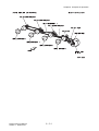
4.2 DRIVE ASSY TRANS
The torque of the DRIVE ASSY TRANS is transmitted through the route below.
! "#$%&' ( )
[ Name of moving parts ]
[ BELT ]
[ ROLL ASSY DRIVE ENT ]
[ BELT ]
[ BELT ]
[ SHAFT ASSY MAIN PADDLE ]
[ PADDLE SUB ]
[ PADDLE SUB ]
[ ROLL ASSY DRIVE EXIT ]
Finisher Service Manual
Version 1 2009.03.31
6 – 32
Chapter 6 Principles of Operation
!
[ Name of moving parts ]
" #$%&'() *( (#+'+(,(# - +(').
/0 1 3
330 45
[ BELT ]
/0 [ ROLL ASSY DRIVE ENT ]
/0 2
/0 [ BELT ]
[ PADDLE SUB ]
[ ROLL ASSY DRIVE EXIT ]
/0 16 330 3
[ SHAFT ASSY MAIN PADDLE ]
12 Finisher Service Manual
Version 1 2009.03.31
6 – 33
Chapter 6 Principles of Operation
4.3 MOTOR ASSY EJECT DRIVE
During sheet transfer from the X' port to the Compile Tray, the torque of the MOTOR ASSY EJECT
DRIVE is transmitted through the route below.
$ % &'() *+,('"-
[ Name of moving parts ]
[ BELT ]
[ BELT ]
[ ROLLER ASSY EJECT PINCH ]
[ GUIDE PAPER 240 ]
Finisher Service Manual
Version 1 2009.03.31
6 – 34
!"
#
Chapter 6 Principles of Operation
[ Name of moving parts ]
! "#$%&'( )' '"*&*''" + *'&(,
[ ROLLER ASSY EJECT PINCH ]
8 38
- ./0 1
- ./ 8 114 38
- 23345
. 67
- 114 . 5
:4
- . 1
[ GUIDE PAPER 240 ]
[ GUIDE PAPER 240 ]
[ BELT ]
[ BELT ]
- ./3
- . - 1145
1 6
- .0 . /0
8 114 19 1145
-2 - 23345
./3 - ./
329 36
- . 3
329 ./6
Finisher Service Manual
Version 1 2009.03.31
6 – 35
Chapter 6 Principles of Operation
4.4 MOTOR ASSY EJECT DRIVE
During sheet ejection from the Compile Tray to the Stacker Tray, the torque of the MOTOR ASSY
EJECT DRIVE is transmitted through the route below.
% ! & '( #)*+,- -)./
[ Name of moving parts ]
! [ BELT ]
[ BELT ]
[ ROLLER ASSY EJECT PINCH ]
[ ROLLER ASSY EJECT ]
[ SHAFT ASSY SET CLAMP ]
! [ GUIDE PAPER 240 ]
Finisher Service Manual
Version 1 2009.03.31
6 – 36
"#
$
Chapter 6 Principles of Operation
!"
[ Name of moving parts ]
# $%&' ( $))*$ + ) ',
[ ROLLER ASSY EJECT PINCH ]
8 28
- .0/ - .0 8 3 28
- 12234
. 56
[ ROLLER ASSY EJECT ]
- 3 .7 4
:3
[ GUIDE PAPER 240 ]
[ GUIDE PAPER 240 ]
[ BELT ]
[ BELT ]
- .02
- . - 34
5
- ./ . 0/
8 3 - 12234
.02 7
- .0
9 3 -1 219 25
- .7 2
8 4
28 8
[ SHAFT ASSY SET CLAMP ]
219 .05
- .
/
- . Finisher Service Manual
Version 1 2009.03.31
6 – 37
Chapter 6 Principles of Operation
4.5 MOTOR ASSY TAMPER
The torque of the MOTOR ASSY TAMPER is transmitted through the route below.
[ Name of moving parts ]
[ GUIDE TAMPER FRONT ]
[ GUIDE TAMPER REAR ]
#
!"
Finisher Service Manual
Version 1 2009.03.31
6 – 38
Chapter 6 Principles of Operation
[ Name of moving parts ]
[ GUIDE TAMPER REAR ]
[ GUIDE TAMPER FRONT ]
"#
Finisher Service Manual
Version 1 2009.03.31
6 – 39
! "#
! Chapter 6 Principles of Operation
4.6 DRIVE ASSY STACKER
The torque of the DRIVE ASSY STACKER is transmitted through the route below.
[ Name of moving parts ]
[ BELT ]
[ BELT STACKER ]
[ CARRIAGE ASSY & TRAY STACKER ]
Finisher Service Manual
Version 1 2009.03.31
6 – 40
Chapter 6 Principles of Operation
[ Name of moving parts ]
[ CARRIAGE ASSY & TRAY STACKER ]
! "
[ BELT ]
[ BELT STACKER ]
Finisher Service Manual
Version 1 2009.03.31
6 – 41
Chapter 7 Wiring Diagrams and Signal Information
Chapter 7 Wiring Diagrams and Signal Information CONTENTS
1. Connection Wiring Diagram.........................................................................................7 - 1
1.1 Symbols in the General Connection Wiring Diagram........................................................................ 7 - 1
1.2 General Wiring Diagram ................................................................................................................... 7 - 2
2. Interconnection Wiring Diagram of Parts.....................................................................7 - 3
2.1 Notes on Using the Wiring Diagram between Parts.......................................................................... 7 - 3
2.2 Configuration of the Interconnection Wiring Diagram of Parts.......................................................... 7 - 5
§ 1 DC POWER SUPPLY & SWITCH ................................................................................................... 7 - 7
§ 2 H-TRANSPORT, X' PORT & COMPILER TRAY ............................................................................. 7 - 9
§ 3 STACKER ...................................................................................................................................... 7 - 11
§ 4 STAPLER....................................................................................................................................... 7 - 13
Finisher Service Manual
Version 1 2009.03.31
Chapter 7 Wiring Diagrams and Signal Information
1. Connection Wiring Diagram
1.1 Symbols in the General Connection Wiring Diagram
The symbols in the general connection wiring diagram are described below.
Symbol
Description
Represents an interconnection between parts using wiring harness or wire.
Represents an interconnection which differs according to the specifications.
Represents an interconnection between parts using a conductive member
such as a plate spring.
Represents a connection between parts by tightening of a screw.
Indicates a frame ground.
Represents a connector. The connector No. is indicated inside the box.
Represents a connection terminal with a plate spring on the printed circuit
board. The connector (terminal) No. is indicated inside the box.
Represents a connector directly connected to the printed circuit board. The
connector No. is indicated inside the box.
The box containing a part name represents a part.
"PL X.Y.Z" indicates the item "Z" of the plate (PL) "X.Y" described in
Chapter 5 "Parts List."
Represents a functional part within a part, and indicates the name of the
functional part.
Represents a section in "2. Interconnection Wiring Diagram of Parts," and
indicates its section No.
Represents a screw for fixing wiring harness and a conductive member such
as a plate spring.
Represents a conductive member such as a plate spring.
Finisher Service Manual
Version 1 2009.03.31
7-1
Chapter 7 Wiring Diagrams and Signal Information
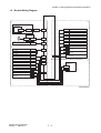
1.2 General Wiring Diagram
PWBA MAIN A4 FIN
PL14.4.12
1
3
Printer
PWBA MCU
PL10.2.18
P/J22
P/J121
CN 4
P/J 8990
LVPS ASSY
PL14.10.10
P/J 590
P/J 591
SWITCH (FRONT DOOR SWITCH)
P/J 8889
PL14.10.3
P/J 8872
STACKER NO PAPER SENSOR
PL14.9.10
P/J 8870
EJECT CLAMP HOME SENSOR
PL14.4.3
P/J 8871
SET CLAMP HOME SENSOR
PL14.4.3
P/J 8873
STACKER HEIGHT SENSOR 1
PL14.4.3
P/J 8874
STACKER HEIGHT SENSOR 2
PL14.4.3
P/J 8876
SOLENOID ASSY
PL14.6.20
P/J 8877
CLUTCH Z34
PL14.5.25
P/J 8878
MOTOR ASSY EJECT
PL14.5.6
P/J 8980
P/J 8982
2
HTU-HXPORT OPEN SENSER
PL14.2.36
P/J 8864
MOTOR ASSY PM HTU
PL14.2.16
P/J 8863
COMPILEVEXIT SENSOR
PL14.7.9
P/J 8869
P/J 8989
DRIVE ASSY TRANS
PL14.7.16
P/J 8879
P/J 8984
COMPILE TRAY NO PAPER
PL14.8.13
P/J 8880
P/J 8988
P/J 8987
MOTOR ASSY STACKER
PL14.9.7
P/J 8986
4
STAPLER ASSY
PL14.8.20
FRONT TAMPER HOME SENSOR
P/J 8881
PL14.8.9
P/J 8886
REAR TAMPER HOME SENSOR
PL14.8.9
P/J 8882
P/J 8887
MOTOR ASSY TAMPER (REAR)
PL14.8.18
P/J 8883
P/J 8983
MOTOR ASSY TAMPER (FRONT)
P/J 8884
PL14.8.18
FIN07001KA
Finisher Service Manual
Version 1 2009.03.31
7-2
Chapter 7 Wiring Diagrams and Signal Information
2. Interconnection Wiring Diagram of Parts
2.1 Notes on Using the Wiring Diagram between Parts
The following describes the legend of the wiring diagrams between parts shown on the following pages.
Symbols
Description
Denotes a plug.
Denotes a jack.
P/JXX
YY
PWBA HNB DRV
(PL X.Y.Z)
Heater
Control
DEVE_A
REGI CLUTCH ON(L)+24VDC
EXIT PAPER SENSED(L)+3.3VDC
Finisher Service Manual
Version 1 2009.03.31
Denotes Pin yy and Jack yy of the connector Pxx and Jxx.
Denotes the parts.
PL X.Y.Z implies the item "Z" of plate (PL) "X.Y" in Chapter 5.
Parts List.
Denotes functional parts attached with functional parts name.
Denotes the control and its outline in PWB.
Denotes a connection between parts with harnesses or wires,
attached with signal name/contents.
Denotes the function, and logic value of the signal to operate the
function (Low: L, High: H).
The given voltage is for signal in high status.
The arrow indicates the direction of signal.
Denotes the function, and logic value of the signal when the function operated (Low: L, High: H).
The given voltage is for signal in high status.
The arrow indicates the direction of signal.
7-3
Chapter 7 Wiring Diagrams and Signal Information
Symbols
Description
Denotes a connection between wires.
I/L +24VDC
+5VDC
+3.3VDC
Denotes DC voltage when the interlock switch in HNB MCU WITH
CPU turns on.
Denotes DC voltage.
SG
Denotes signal ground.
AG
Denotes analog ground.
RTN
Finisher Service Manual
Version 1 2009.03.31
Denotes the return.
7-4
Chapter 7 Wiring Diagrams and Signal Information
2.2 Configuration of the Interconnection Wiring Diagram of Parts
The interconnection wiring diagram is divided into 4 sections.
§ 1 to § 4 indicate details of the interconnections of parts.
§ 1 DC POWER SUPPLY & SWITCH
Connections of Printer with PWBA MAIN A4 FIN.
Connections of LVPS ASSY with PWBA MAIN A4 FIN.
Connections of SWITCH with PWBA MAIN A4 FIN.
§ 2 H-TRANSPORT, X' PORT & COMPILER
Connections of HTU-HXPORT OPEN SENSOR with PWBA MAIN A4 FIN.
Connections of MOTOR ASSY PM HTU with PWBA MAIN A4 FIN.
Connections of COMPILE EXIT SENSOR with PWBA MAIN A4 FIN.
Connections of DRIVE ASSY TRANS with PWBA MAIN A4 FIN.
Connections of COMPILE TRAY NO PAPER SENSOR with PWBA MAIN A4 FIN.
Connections of FRONT TAMPER HOME SENSOR with PWBA MAIN A4 FIN.
Connections of REAR TAMPER HOME SENSOR with PWBA MAIN A4 FIN.
Connections of MOTOR ASSY TAMPER (REAR) with PWBA MAIN A4 FIN.
Connections of MOTOR ASSY TAMPER (FRONT) with PWBA MAIN A4 FIN.
§ 3 STACKER
Connections of STACKER NO PAPER SENSOR with PWBA MAIN A4 FIN.
Connections of EJECT CLAMP HOME SENSOR with PWBA MAIN A4 FIN.
Connections of SET CLAMP HOME SENSOR with PWBA MAIN A4 FIN.
Connections of STACKER HEIGHT SENSOR 1 with PWBA MAIN A4 FIN.
Connections of STACKER HEIGHT SENSOR 2 with PWBA MAIN A4 FIN.
Connections of SOLENOID ASSY with PWBA MAIN A4 FIN.
Connections of CLUTCH Z34 with PWBA MAIN A4 FIN.
Connections of MOTOR ASSY EJECT with PWBA MAIN A4 FIN.
Connections of MOTOR ASSY STACKER with PWBA MAIN A4 FIN.
§ 4 STAPLER
Connections of STAPLER ASSY with PWBA MAIN A4 FIN.
Finisher Service Manual
Version 1 2009.03.31
7-5
Chapter 7 Wiring Diagrams and Signal Information
BLANK PAGE
Finisher Service Manual
Version 1 2009.03.31
7-6
Chapter 7 Wiring Diagrams and Signal Information
§ 1 DC POWER SUPPLY & SWITCH
Printer
PWBA MAIN A4 FIN
PL14.4.12
PWBA MCU
PL10.2.18
HARNESS ASSY FIN
PL11.1.8
PJ22
xDETECT_FIN
1
xEXIT_SNR_FIN
2
LVSQ_FIN
3
4
PJ121
xDETECT COMMANDER
5
6
7
8
TxD_FIN
RxD_FIN
SG
CN4
1
1
2
2
3
3
6
6
9
9
10 10
11 11
RLY 24V
12 12
HARNESS ASSY IF A4FIN
PL14.11.7
P/J8990
IOT DETECT
1
IOT EXIT
2
PS ENB
3
NC
4
CMD
5
STA
6
SG
6
NC
HARNESS ASSY FIN PWR
LVPS ASSY
PL10.1.14
PL10.2.2
P/J311
OUT_LINE
1
NC
2
OUT_NUTRAL
3
T171
CABLE ASSY POWER A4FIN
PL14.11.8
J590
L
1
NC
2
N
3
LVPS ASSY
PL14.10.10
P/J591
1
2
3
4
SWITCH
(FRONT DOOR SWITCH)
PL14.10.13
HARNESS ASSY LVPS A4FIN
PL14.11.1
P/J8980
+24V PS
1
SG
2
PS_ENB
3
SG
4
HARNESS ASSY INTL SW A4FIN
PL14.11.2
P/J8889
+24V PS
1
2
FIN FRONT DOOR SW
P/J8982
1
2
FIN07002KA
Finisher Service Manual
Version 1 2009.03.31
7-7
Chapter 7 Wiring Diagrams and Signal Information
Signal line name
Description
xDETECT_FIN
xEXIT_SNR_FIN
LVSQ_FIN
Communication signal of PWB A MCU (Engine) and PWB MAIN A4
xDETECT COMMANDER FIN(Finisher)
TxD FIN
RxD FIN
PS_ENB
Control signal of the LVPS
FIN FRONT DOOR SW
Control signal of the Switch(Front Door)
Finisher Service Manual
Version 1 2009.03.31
7-8
Chapter 7 Wiring Diagrams and Signal Information
§ 2 H-TRANSPORT, X' PORT & COMPILER TRAY
PWBA MAIN A4 FIN
PL14.4.12
+5VDC
HARNESS ASSY HTU A4FIN
PL14.2.40
P/J8987
1
2
3
11
12
13
14
+5VDC
P/J8989
P/J8864
3
2
1
XPORT MOT A
XPORT MOT /A
XPORT MOT B
XPORT MOT /B
P/J8863
6
2
5
1
HARNESS ASSY SNR2 A4FIN
PL14.11.6
SG
COMP EXIT SNR
VCC
10B
11B
12B
P/J8984
9
10
11
12
+5VDC
SG
HTU OPEN SNR
VCC
HARNESS ASSY MOT2 A4FIN
PL14.11.4
TRANSPORT MOT B
TRANSPORT MOT /A
TRANSPORT MOT /B
TRANSPORT MOT A
HTU-HXPORT OPEN SENSOR
PL14.2.36
P/J8869
3
2
1
COMPILE EXIT SENSOR
PL14.7.9
P/J8879
4
5
1
2
DRIVE ASSY TRANS
PL14.7.16
M
HARNESS ASSY SNR1
HARNESS ASSY COMP1
A4FIN PL14.11.5
A4FIN PL14.8.23
P/J8890
P/J8880
P/J8988
SG
3
1
9 1
COM NO PAPER SNR
2
2
8 2
VCC
1
3
7 3
+5VDC
MOTOR ASSY PM HTU
PL14.2.16
M
COMPILE TRAY NO PAPER
SENSOR
PL14.8.13
4
5
6
SG
F TAMPER HOME SNR
VCC
6 4
5 5
4 6
P/J8881
3
2
1
FRONT TAMPER HOME
SENSOR
PL14.8.9
7
8
9
SG
R TAMPER HOME SNR
VCC
3 7
2 8
1 9
P/J8882
3
2
1
REAR TAMPER HOME
SENSOR
PL14.8.9
+5VDC
P/J8983
5
6
7
8
9
HARNESS ASSY MOT1
HARNESS ASSY COMP2
A4FIN PL14.11.4
A4FIN PL14.8.24
P/J8891
P/J8883
R TAMPER A
10 1
6 1
SOL 24V
9 2
5 2
R TAMPER /A
8 3
4 3
R TAMPER B
7 4
3 4
R TAMPER /B
6 5
1 6
M
MOTOR ASSY TAMPER
(REAR)
PL14.8.18
M
MOTOR ASSY TAMPER
(FRONT)
PL14.8.18
P/J8884
10
11
12
13
14
F TAMPER A
SOL 24V
F TAMPER /A
F TAMPER B
F TAMPER /B
5
4
3
2
1
6
7
8
9
10
6
5
4
3
1
1
2
3
4
6
FIN07003KA
Finisher Service Manual
Version 1 2009.03.31
7-9
Chapter 7 Wiring Diagrams and Signal Information
Signal line name
Description
HTU OPEN SNR
Opening/closing detection signal of "COVER TOP H-TRA"
XPORT MOT A
XPORT MOT /A
XPORT MOT B
XPORT MOT /B
Drive control signal of the MOTOR ASSY PM HTU.
COMP EXIT SNR
Transport paper detection signal to Compile Tray by SENSOR (Compile
Exit Sensor)
TRANSPORT MOT A
TRANSPORT MOT /A
TRANSPORT MOT B
TRANSPORT MOT /B
Drive control signal of the DRIVE ASSY TRANS.
COM NO PAPER SNR
Paper detection signal in Compiler Tray by SENSOR(COMPILE TRAY NO
PAPER)
F TAMPER HOME SNR
Front Tamper home position detection signal by SENSOR (FRONT
TAMPER HOME SENSOR)
R TAMPER HOME SNR
Rear Tamper home position detection signal by SENSOR (REAR
TAMPER HOME SENSOR)
R TAMPER A
R TAMPER /A
R TAMPER B
R TAMPER /B
Drive control signal of the MOTOR ASSY TAMPER (REAR).
F TAMPER A
F TAMPER /A
F TAMPER B
F TAMPER /B
Drive control signal of the MOTOR ASSY TAMPER (FRONT).
Finisher Service Manual
Version 1 2009.03.31
7 - 10
Chapter 7 Wiring Diagrams and Signal Information
§ 3 STACKER
PWBA MAIN A4 FIN
PL13.4.12
+5VDC
HARNESS ASSY SNR2 A4FIN
PL14.11.6
P/J8989
SG
4A
STACK NO PAPER SNR
5A
VCC
6A
+5VDC
10A
11A
12A
SG
EJECT CLAMP HOME SNR
VCC
P/J8870
3
2
1
1B
2B
3B
SG
SET CLAMP HOME SNR
VCC
P/J8871
3
2
1
4B
5B
6B
SG
STACK HEIGHT SNR1
VCC
P/J8873
3
2
1
7B
8B
9B
SG
STACK HEIGHT SNR2
VCC
P/J8874
3
2
1
+5VDC
+5VDC
+5VDC
+24VDC
P/J8872
3
2
1
P/J8984
1
2
3
4
HARNESS ASSY MOT2 A4FIN
PL14.11.4
STACKER NO PAPER SENSOR
PL14.9.10
EJECT CLAMP HOME SENSOR
PL14.4.3
SET CLAMP HOME SENSOR
PL14.4.3
STACKER HEIGHT SENSOR1
PL14.4.3
STACKER HEIGHT SENSOR2
PL14.4.3
SOL 24V
SUB PAD SOL
P/J8876
1
2
SOLENOID ASSY
PL14.6.20
SOL 24V
SET CLAMP CLUTCH
P/J8877
2 1
1 2
CLUTCH Z34
PL14.5.25
P/J8878
5
6
7
8
EJECT MOT B
EJECT MOT /B
EJECT MOT A
EJECT MOT /A
1
3
4
6
HARNESS ASSY MOT3 A4FIN
PL14.9.25
P/J8986
1
2
3
4
STACKER MOT A
STACKER MOT / A
STACKER MOT B
STACKER MOT / B
M
MOTOR ASSY EJECT
PL14.5.6
M
MOTOR ASSY STACKER
PL14.9.7
P/J8878
1
2
5
6
FIN07004KA
Finisher Service Manual
Version 1 2009.03.31
7 - 11
Chapter 7 Wiring Diagrams and Signal Information
Signal line name
Description
STACK NO PAPER SNR
Paper detection signal in Stack Tray by SENSOR (STACKER NO PAPER
SENSOR)
EJECT CLAMP HOME Eject Clamp home position detection signal by SENSOR (EJECT CLAMP
SNR
HOME SENSOR)
SET CLAMP HOME SNR
Set Clamp home position detection signal by SENSOR (SET CLAMP
HOME SENSOR)
STACK HEIGHT SNR1
Height detection signal of Stack Tray by SENSOR (STACKER HEIGHT
SENSOR1)
STACK HEIGHT SNR2
Height detection signal of Stack Tray by SENSOR (STACKER HEIGHT
SENSOR2)
SUB PAD SOL
SOLENOID ASSY(Sub Paddle Solenoid) ON/OFF control signal
SET CLAMP CLUTCH
CLUTCH Z34(Set Clamp Clutch) ON/OFF control signal
EJECT MOT A
EJECT MOT /A
EJECT MOT B
EJECT MOT /B
Drive control signal of the MOTOR ASSY EJECT.
STACKER MOT A
STACKER MOT /A
STACKER MOT B
STACKER MOT /B
Drive control signal of the D MOTOR ASSY STACKER.
Finisher Service Manual
Version 1 2009.03.31
7 - 12
Chapter 7 Wiring Diagrams and Signal Information
§ 4 STAPLER
STAPLER ASSY
PL14.8.20
PWBA MAIN A4 FIN
PL14.4.12
P/J8983
1
2
3
4
P/J8988
10
11
12
13
14
HARNESS ASSY MOT1 A4FIN
PL14.11.3
STAPLE CW(+)
STAPLE CW(+)
STAPLE CCW(-)
STAPLE CCW(-)
HARNESS ASSY SNR1 A4FIN
PL14.11.5
VCC
STAPLE HOME SNR
SELF PRIMING SNR
LOW STAPLE SNR
SG
P/J8887
1
2
3
4
P/J8886
5
4
3
2
1
M
Staple Motor
Staple
Home
Sensor
Self
Priming
Sensor
Low
Staple
Sensor
FIN07005KA
Finisher Service Manual
Version 1 2009.03.31
7 - 13
Chapter 7 Wiring Diagrams and Signal Information
Signal line name
Description
STAPLE CW(+)
STAPLE CCW(-)
Drive control signal of the Staple Motor.
STAPLE HOME SNR
Stapler Head home position detection signal by Staple Home Sensor in
STAPLER ASSY
LOW STAPLE SNR
Detection signal of the needle of Stapler by Low Staple Sensor in
STAPLER ASSY.
Finisher Service Manual
Version 1 2009.03.31
7 - 14
Chapter 8 Printer Specifications
Chapter 8 Printer Specifications CONTENTS
1. Configuration of Finisher ............................................................................................8 - 1
1.1 Basic Configuration.......................................................................................................................... 8 - 1
2. Electrical Properties....................................................................................................8 - 2
2.1 Power Supply................................................................................................................................... 8 - 2
2.2 Power Consumption......................................................................................................................... 8 - 2
3. Mechanical Properties ................................................................................................8 - 3
3.1 Dimensions/Mass of Horizontal-Transport....................................................................................... 8 - 3
3.2 Dimensions/Mass of Finisher........................................................................................................... 8 - 3
3.3 Installation Requirements ................................................................................................................ 8 - 4
4. Functions ....................................................................................................................8 - 5
4.1 Stapling ............................................................................................................................................ 8 - 5
4.2 Stacker Tray Ejection Mode............................................................................................................. 8 - 5
4.3 Paper Stack Capacity ...................................................................................................................... 8 - 5
4.4 Paper Size and Available Functions ................................................................................................ 8 - 5
4.5 Stapling Position .............................................................................................................................. 8 - 6
4.6 Processing Speed............................................................................................................................ 8 - 6
5. Consumables..............................................................................................................8 - 7
5.1 Items of Consumables ..................................................................................................................... 8 - 7
5.2 Consumable Life .............................................................................................................................. 8 - 7
6. Operating Environment...............................................................................................8 - 8
6.1 Ambient Temperature/Humidity ....................................................................................................... 8 - 8
6.2 Installation Levelness....................................................................................................................... 8 - 8
6.3 Ambient Lighting .............................................................................................................................. 8 - 8
7. Safety/Environment Conditions ..................................................................................8 - 9
7.1 Safety Standard ............................................................................................................................... 8 - 9
7.2 EMI................................................................................................................................................... 8 - 9
Finisher Service Manual
Version 1 2009.03.31
Chapter 8 Printer Specifications
Chapter 8 Printer Specifications CONTENTS
Finisher Service Manual
Version 1 2009.03.31
Chapter 8 Printer Specifications
1. Configuration of Finisher
1.1 Basic Configuration
The Finisher consists of "Horizontal-Transport", "Stacker Tray", and "Finisher Main Unit".
The Finisher functions only when installed to the printer.
Tbt08100KB
Finisher Service Manual
Version 2 2009.06.10
8–1
Chapter 8 Printer Specifications
2. Electrical Properties
2.1 Power Supply
The Finisher receives AC power from the printer it is connected to (100 to 240 VAC).
2.2 Power Consumption
65 VA or less
Finisher Service Manual
Version 1 2009.03.31
8–2
Chapter 8 Printer Specifications
3. Mechanical Properties
3.1 Dimensions/Mass of Horizontal-Transport
Width (mm)
Depth (mm)
Height (mm)
Mass (kg)
429.8
256.3
115.8
1.7 or less
Tbt08101KB
3.2 Dimensions/Mass of Finisher
Width (mm)
Depth (mm)
Height (mm)
Mass (kg)
490.2
516
524.7
14.0 or less
Tbt08102KB
Finisher Service Manual
Version 2 2009.06.10
8–3
Chapter 8 Printer Specifications
3.3 Installation Requirements
The finisher requires the minimum installation space shown below for typical operation.
(Space occupied by the operator is not included.)
Top view
60mm
Tbt08103KA
Finisher Service Manual
Version 1 2009.03.31
8–4
Chapter 8 Printer Specifications
4. Functions
4.1 Stapling
- Stapling Position: Front Corner
- Maximum Stapling Capacity: 50 sheets (90 g/m2 or less)
- Staple Capacity: 5,000 or more
4.2 Stacker Tray Ejection Mode
The ejection mode is automatically selected from Set Mode and Sheet Mode depending on the paper
size.
- Set Mode: The sheets are deposited in the Compile Tray, and then ejected to the Stacker Tray.
- Sheet Mode: The sheets are directly ejected to the Stacker Tray. Offset stacking and stapling cannot
be used in this mode.
4.3 Paper Stack Capacity
Tray
Paper Size
Stacker Tray
(Set Mode)
Stacker Tray
(Sheet Mode)
Non-staple
Staple
A4
B5
A5
Letter
Executive
C5
1,000 sheets
50 sets or 750 sheets
Legal
750 sheets
50 sets or 500 sheets
Other than those above 300 sheets
-
4.4 Paper Size and Available Functions
Stacker
Offset
Staple
Yes
Yes
Yes
No
Yes
No
No
B5 (182 x 257 mm)
Yes
Yes
Yes
Yes
Letter (8.5 x 11 in.)
Yes
Yes
Yes
Yes
Folio (8.5 x 13 in.)
Yes
No
Yes
Yes
Legal (8.5 x 14 in.)
Yes
Yes
Yes
Yes
Paper Size
Set Mode
Sheet Mode
A4 (210 x 297 mm)
Yes
A5 (148 x 210 mm)
Executive (7.25 x 10.5 in.)
Yes
Yes
Yes
Yes
Envelope #10 (4.125 x 9.5 in.)
No
Yes
No
No
Monarch (3.875 x 7.5 in.)
No
Yes
No
No
Yes: Supported
Finisher Service Manual
Version 1 2009.03.31
No: Not Supported
8–5
Chapter 8 Printer Specifications
4.5 Stapling Position
4.6 Processing Speed
The processing speed of the Finisher depends on that of the Printer.
Finisher Service Manual
Version 1 2009.03.31
8–6
Chapter 8 Printer Specifications
5. Consumables
5.1 Items of Consumables
- Staple cartridge
5.2 Consumable Life
- Staple cartridge: 5,000 staples
Finisher Service Manual
Version 1 2009.03.31
8–7
Chapter 8 Printer Specifications
6. Operating Environment
6.1 Ambient Temperature/Humidity
The ambient temperature and humidity of the installation site shall be as follows:
At operation: 10-32 °C, 15-85%RH (Non-condensing)
6.2 Installation Levelness
When secured to the Printer, the Finisher shall not malfunction at a tilt of 1° to the front, back, right, or
left.
6.3 Ambient Lighting
3000 lux or less (without direct sunlight)
Finisher Service Manual
Version 1 2009.03.31
8–8
Chapter 8 Printer Specifications
7. Safety/Environment Conditions
7.1 Safety Standard
- 100V system
UL60950-1
CSA C22.2 No.60950
- 220V system
IEC60950
7.2 EMI
- 100/110V system (US)
FCC Part 15, Subpart B, Class B
- 220V system (EC)
EN55022, Class B
Finisher Service Manual
Version 1 2009.03.31
8–9