1
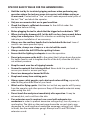
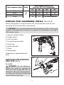
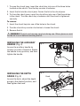
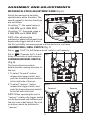
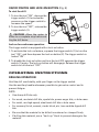
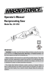
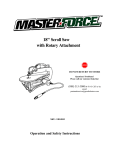
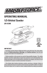
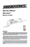
Owner’s Manual
Hammer Drill
241-0738
IMPORTANT:
Read through this Owner’s Manual carefully before using this tool. Pay
close attention to all Safety Instructions, Warnings, and Cautions. Use this
tool properly, and only for its intended use.
Safety symbols in this Manual are used to flag possible dangers. The safety symbols and their explanations require your full understanding. The safety
warnings do not eliminate any danger by themselves, and they are not a substitute for proper accident prevention measures.
This Safety Alert Symbol indicates caution, warning, or danger. Failure to
obey a safety warning can result in serious injury to yourself or others. To reduce
the risk of injury, fire, or electric shock, always follow the safety precautions.
TABLE OF CONTENTS
Specifications…………..…………………………………………...Page 2
Rules for Safe Operation……………..……………………………...Page 3
Know the Hammer Drill…………………………………………….. Page 7
Assembly and Adjustments……………………………………….....Page 9
Operating Instructions…..……………………………………….......Page 10
Maintenance……………………………………………………........Page 12
Trouble Shooting…..……………………………………………........Page 13
Warranty……………..…………………………………………........Page 14
SPECIFICATIONS
Model:
Motor:
Keyed chuck:
Variable speed ranges:
Hammer:
Maximum drilling capacity:
Weight:
241-0738
120 V, 60 Hz, 7.5 A
1/2” (13 mm)
0–1080 & 0–3000 RPM
0–18,000 & 0–48,000 BPM
1/2” in steel
1/2” in Concrete (3/16”-3/8” Optimum)
1 1/4” in Wood
7 lb 8 oz (3.4 kg)
SAFETY SYMBOLS FOR YOUR TOOL
The label on your tool may include the following symbols
V ..............................................................Volts
A ..............................................................Amps
Hz ............................................................Hertz
W .............................................................Watts
min ..........................................................minutes
..........................................................Alternating current
.........................................................Direct current
..............................................................
n
No load speed
...........................................................Class II construction,Double insulated
.../min .....................................................Revolutions or Strokes per minute
...........................................................Indicates danger,warning or caution.
It means attention!Your safety is involved
.......................................................... Wet Conditions Alert! Do not expose to
rain or use in damp locations
2
o
RULES FOR SAFE OPERATION
KNOW THE TOOL
To operate this tool, carefully read this Owner’s Manual and all labels affixed
to the hammer drill before using it. Keep this Manual for future reference.
IMPORTANT
This tool should only be serviced by a qualified service technician. For more
information, call the toll-free helpline, at 1-866-917-4374.
READ ALL INSTRUCTIONS THOROUGHLY
GENERAL SAFETY PRECAUTIONS
WARNING: Read and understand all instructions. Failure to follow all instructions listed below may result in electric shock, fire and/or serious personal injury.
SAVE THESE INSTRUCTIONS.
WORK AREA
• K
eep your work area clean and well lit. Cluttered benches and dark areas
invite accidents.
• Do
not operate power tools in explosive atmospheres, such as in the
presence of flammable liquids, gases, or dust. Power tools create sparks
which may ignite the dust or fumes.
• K
eep bystanders, children, and visitors away while operating a power
tool. Distractions can cause you to lose control.
Electrical Safety
• D
ouble insulated tools are equipped with a
polarized plug (one blade is wider than the other).
This plug will fit in a polarized outlet only one
way. If the plug does not fit fully in the outlet,
reverse the plug. If it still does not fit, contact a
qualified electrician to install a polarized outlet.
Do not change the plug in any way. Double
insulation eliminates the need for the three
wire grounded power cord and grounded power
supply system.
3
Fig. 1
120
V~
60H
z
• A
void body contact with grounded surfaces such as pipes, radiators,
ranges and refrigerators. There is an increased risk of electric shock if
your body is grounded.
• Don’t
expose power tools to rain or wet conditions. Water entering a
power tool will increase the risk of electric shock.
• Do
not abuse the cord. Never use the cord to carry the tool or to pull
the plug from an outlet. Keep the cord away from heat, oil, sharp edges
or moving parts. Replace damaged cords immediately. Damaged cords
increase the risk of electric shock.
• When
operating a power tool outside, use an outdoor extension cord
marked “W-A” or “W”. These cords are rated for outdoor use and reduce
the risk of electric shock.
Personal Safety
• S
tay alert, watch what you are doing and use common sense when
operating a power tool. Do not use the tool while tired or under the
influence of drugs, alcohol, or medication. A moment of inattention while
operating power tools may result in serious personal injury.
• Dress
properly. Do not wear loose clothing or jewelry. Contain long hair.
Keep your hair, clothing, and gloves away from moving parts. Loose
clothes, jewelry, or long hair can be caught in moving parts.
• Avoid
accidental starting. Be sure that the switch is off before plugging in
the tool. Carrying tools with your finger on the switch or plugging in tools
that have the switch on invites accidents.
• R
emove adjusting keys or wrenches before turning the tool on. A wrench
or a key that is left attached to a rotating part of the tool may result in
personal injury.
• D
o not overreach. Keep proper footing and balance at all times. Proper
footing and balance enable better control of the tool in unexpected
situations.
• U
se safety equipment. Always wear eye protection. Dust mask, non-skid
safety shoes, hard hat, or hearing protection must be used for appropriate
conditions.
• B
efore connecting the tool to a power source (receptacle, outlet, etc.),
be sure that the voltage supplied is the same as that specified on the
nameplate of the tool. A power source with voltage greater than that
specified for the tool can result in serious injury to the user – as well as
damage to the tool.
4
Tool Use and Care
• U
se clamps or another practical way to support and secure the workpiece
to a stable platform. Holding the work by hand or against your body is
unstable and may lead to loss of control.
• D
o not force the tool. Use the correct tool for your application. The
correct tool will do the job better and more safely at the rate for which is
designed.
• Do
not use the tool if the switch does not turn it on or off. Any tool that
cannot be controlled with the switch is dangerous and must be repaired.
• D
isconnect the plug from the power source before making any adjustments,
changing accessories, or storing the tool. Such preventive safety measures
reduce the risk of starting the tool accidentally.
• S
tore idle tools out of reach of children and other untrained persons. Tools
are dangerous in the hands of untrained users.
• M
aintain tools with care. Keep cutting tools sharp and clean. Properly
maintained tools with sharp cutting edges are less likely to bind and are
easier to control.
• C
heck for misalignment or binding of moving parts, breakage of parts,
and any other condition that may affect the tool’s operation. If damaged,
have the tool serviced before using. Many accidents are caused by poorly
maintained tools.
• U
se only accessories that are recommended by the manufacturer for
your model. Accessories that may be suitable for one tool may become
hazardous when used on another tool.
• D
o not alter or misuse tool. This tool is precision built. Any alteration
or modification not specified is misuse and may result in a dangerous
condition.
Service
• Tool
service must be performed only by qualified repair personnel. Service
or maintenance performed by unqualified personnel could result in a risk
of injury.
• W
hen servicing a tool, use only identical replacement parts. Follow
instructions in the Maintenance section of this manual. Use of unauthorized
parts or failure to follow Maintenance instructions may create a risk of
electric shock or injury.
5
SPECIFIC SAFETY RULES FOR THE HAMMER DRILL
• H
old the tool by its insulated gripping surfaces when performing any
operation where the tool may come into contact with hidden wiring or
its own cord. Contact with a “live” wire will make exposed metal parts of
the tool “live” and shock the operator.
• O
nly use accessories that are in good condition.
• C
heck that there is sufficient clearance for the drill bit under the
workpiece before drilling,
• B
efore plugging the tool in, check that the trigger lock-on button is “OFF”.
• W
hen starting the hammer drill, let the drill run for a few seconds before
using it on a workpiece. Watch for vibration or wobbling that could
indicate poor installation of an accessory.
• A
lways use the auxiliary handle that is included with the tool. Loss of
control can cause personal injury.
• I f possible, always use clamps or a vise to hold the work.
• A
lways switch the drill OFF before putting it down.
• E nsure that the lighting is adequate to see the operation.
• D
o not put pressure on the drill to the extent that it slows down the motor.
For better results, and to lengthen the life of the drill, allow the drill bit to
cut without pressure.
• K
eep the work area free of tripping hazards.
• S
ecure the material that is being drilled. Never hold it in your hand or
across your hand or across your legs.
• D
o not use damaged or bowed drill bits.
• K
eep hands away from rotating parts.
• A
lways wear safety goggles and a dust mask when drilling, especially
when drilling above the level of your head.
• W
atch out for flying sparks. Hold the tool so that any sparks will fly away
from the operator and other persons. Keep all flammable materials away
when using this drill.
• D
o not touch the workpiece immediately after operation. It may be
extremely hot, and could burn the skin.
• I f an extension cord is required, use a cord with adequate size
conductors in order to prevent excessive voltage drop, loss of power, or
overheating. The table on the next page shows the correct size to use,
depending on cord length and nameplate amperage rating of tool. When
in doubt, use the next heavier gauge. Always use UL and CSA listed
extension cords.
6
Tool’s Ampere rating
Volts
0-6
6-10
10-12
12-16
120
V~
Total length of cord in feet
Cord size in A. W. G.(minimum)
25’
50’
100’
150’
18
16
16
14
18
16
14
12
16
16
14
12
14
12
Not Recommended
KNOW THE HAMMER DRILL (See Fig. 2)
Before attempting to use this hammer drill, become familiar with all of its
operating features and safety requirements.
WARNING: Do not allow familiarity with the hammer drill to cause carelessness. Remember that a fraction of a second of carelessness is enough to
inflict severe injury.
1. Hammer drill/drill switch
2. Trigger switch
Fig. 2
8
1
3. Lock-on button
4. Forward/reverse switch
7
3
5. Chuck key
9
6. Auxiliary handle
6
7. Chuck
4
2
8. Depth gauge
9. Mechanical speed-adjustment
knob
INSTALLING AND REMOVING
DRILL BITS (Fig. 3)
5
Fig. 3
To install:
WARNING! Do not attempt to
tighten the chuck by gripping the
front part and turning the drill on.
Damage to the tool and personal injury may result. Be sure to tighten the
chuck with the chuck key.
7
1. T o open the chuck jaws, insert the chuck key into one of the three holes
located on the chuck. Turn the key counter-clockwise.
2. I nsert the bit into the chuck jaws. Center the bit in the chuck jaws.
3. T o close the chuck jaws, insert the chuck key into one of the three holes
in the chuck. Turn the chuck key clockwise until the chuck is tightened
securely.
To remove:
1. I nsert the chuck key into one of the holes in the chuck.
2. T urn the chuck key counter-clockwise to loosen the chuck.
3. R
emove the bit.
WARNING! The bit can become very hot during use. Wear gloves or wait
for the bit to cool before removing the bit.
INSTALLING THE AUXILIARY
HANDLE (Fig. 4)
Fig. 4
Loosen the auxiliary handle by
turning it counter-clockwise. Rotate
the handle to any position, and then
tighten the handle.
INSTALLING THE DEPTH
GAUGE (Fig. 5)
Fig. 5
Knob
Loosen the knob, adjust the depth
gauge to the desired position, and
then tighten the knob.
8
ASSEMBLY AND ADJUSTMENTS
MECHANICAL SPEED-ADJUSTMENT KNOB (Fig. 6)
Adjust the mechanical variablespeed knob in either direction. The
speed ranges for the two directions
are as follows:
Fig. 6
On setting “I”, the speed range is
0-1080 RPM and 0-18000 BPM.
On setting “II”, the speed range is
0-3000 RPM and 0-48000 BPM.
NOTE: After adjusting the
mechanical speed-adjustment knob,
depress the trigger switch to start
the drill, gradually increasing speed to allow the tool to run freely.
HAMMER DRILL/ DRILL SWITCH (Fig .7)
Set to
(“drill”) to drill holes in wood, metal, or soft masonry.
Set to
(“hammer drill”) to drill
holes in concrete or hard masonry.
Fig. 7
FORWARD/REVERSE SWITCH.
(Fig. 8)
The forward/reverse switch
determines the running direction of
the tool.
1. T o select “forward” motion,
release the trigger switch, and
push the forward/reverse switch
to the right side of the tool.
2. T o select “reverse” motion,
release the trigger switch, and
push the forward/reverse switch
to the left side of the tool.
Fig. 8
Forward
NOTE: When operating the tool in
“reverse” rotation, the trigger switch
can be depressed only halfway and
the tool runs at half speed. The lockon button cannot be activated in
“reverse.”
9
Reverse
ON/OFF SWITCH AND LOCK-ON BUTTON (Fig. 9)
To start the drill:
1. T o turn the tool “ON”, depress the
trigger switch (1). Increase the
pressure on the trigger switch to
increase the speed.
Fig. 9
2
2. T o turn the tool “OFF”, release the
trigger switch (1).
1
CAUTION! Allow the motor to
come to a complete stop before setting the drill down.
Lock on for continuous operation:
The trigger switch is equipped with a lock-on button.
1. T o activate the lock-on feature, squeeze the trigger switch (1) to turn the
tool “ON”, and then depress the lock-on button (2). The trigger switch is
locked “ON”.
2. T o disable the lock-on button and turn the tool OFF, squeeze the trigger
switch (1) again. The lock-on button will disengage. Release the trigger
switch to turn the tool “OFF”.
OPERATING INSTRUCTIONS
DRILLING OPERATION
Hold the drill comfortably, with your finger on the trigger switch.
Use the auxiliary handle whenever possible to gain extra control and to
prevent fatigue.
NOTE:
• U
se sharp drill bits only.
• F or wood, use twist-drill bits, spade bits, power-auger bits, or hole saws.
• F or metal, use high-speed, steel-twist drill bits or hole saws.
• F or masonry (brick, cement, cinder block, etc.) use carbide-tipped drill
bits.
• B
e sure that the material to be drilled is anchored or clamped firmly.
• I f drilling thin material, use a “back-up” block to prevent damage to the
material.
10
To begin drilling
1. W
hen starting a hole, make a mark on the surface of the workpiece, and
then drill a small hole.
2. H
old the drill firmly with both hands.
3. D
epress the trigger switch to start the drill, gradually increasing speed.
For continuous or extended operation, hold the Lock-On button while
depressing the trigger switch.
4. A
pply pressure in line with the bit. Use enough pressure to keep the drill
biting, but do not push hard enough to stall the motor.
NOTE: If the drill begins to stall, reduce the pressure slightly to allow the bit
to regain speed. If the bit binds, reverse the motor to free the bit from the
workpiece.
5. A
fter completing the drilling operation, release the trigger switch, and
allow the bit to come to a complete stop before setting the drill down.
6. W
hen work has been completed, clean the drill to allow for smooth
operation of the drill over time.
WARNING! To reduce the risk of injury, never touch the bit to clean the
debris until the drill has stopped rotating and the bit has cooled down.
Drilling in various materials
1. C
hoose the hammer-drilling function when drilling in hard masonry
(concrete, hard brick, stone, cement, or marble).
2. C
hoose the drilling function when drilling in soft masonry (tile, flooring, soft
brick, lime cement, or cinder block), wood or plastic.
3. W
hen drilling in a smooth surface, attach adhesive paper at the drilling
location to prevent the bit from gliding.
Drilling in wood and plastic
1. S
tart the drill slowly, and increase speed gradually.
2. W
hen using twist drill bits, pull the bit out of the hole frequently to clear
chips from the bit flutes.
3. U
se low speeds for plastic that has a low melting point.
Drilling in metal
1. L ubricate drill bits with cutting oil when drilling in iron or steel.
2. D
o not use a lubricant when drilling in nonferrous metals, such as copper,
brass or aluminium.
11
MAINTENANCE
WARNING: When servicing, use only identical replacement parts. Use of
any other parts may create a hazard or cause product damage. For more information, call the toll-free helpline, at 1-866-917-4374.
WARNING: To ensure safety and reliability, all repairs should be performed
by a qualified service technician.
WARNING: Before cleaning or performing any maintenance, the tool
should be unplugged from the power supply.
WARNING: Using compressed air may be the most effective cleaning
method. Always wear safety goggles when cleaning tools with compressed
air.
GENERAL MAINTENANCE
Avoid using solvents when cleaning plastic parts. Most plastics are
susceptible to damage from various types of commercial solvents and may
be damaged by their use. Use clean cloths to remove dirt, dust, oil, grease,
etc.
Electric tools used on fiberglass material, wallboard, spack-ling compounds,
or plaster are subject to accelerated wear and possible premature failure
because the fiberglass chips and grindings are highly abrasive to bearings,
brushes, commutators, etc. Consequently, we do not recommended using
this product for extended work on these types of materials. However, if you
do work with any of these materials, it is extremely important to clean the
product using compressed air.
LUBRICATION
All of the bearings in this product are lubricated with a sufficient amount of
high grade lubricant for the life of the unit under normal operating conditions.
Therefore, no further lubrication is required.
12
TROUBLESHOOTING
PROBLEM
Motor does not
start.
Drilling is
difficult.
CAUSE OF THE
PROBLEM
SUGGESTED CORRECTIVE ACTION
Tool is not
plugged in
Check that all cords are plugged in.
Fuse
Check the time-delayed fuse or
circuit breaker.
Bit is damaged
Replace the bit.
Wrong bit
Use the proper bit (see OPERATION)
If the problem remains unsolved after performing the checks described
above, call the toll-free helpline, at 1-866-917-4374.
13
WARRANTY
3-MONTH MONEY BACK GUARANTEE:
This MASTERFORCE™ brand power tool carries our 3-Month Money Back
Guarantee. If you are not completely satisfied with your MASTERFORCE™
brand power tool for any reason within three (3) months from the date of
purchase, return the tool with your original receipt to any
retail store, and we will provide you a refund – no questions asked.
3-YEAR LIMITED WARRANTY:
This MASTERFORCE™ brand power tool carries our famous No
Hassle 3-Year Limited Warranty to the original purchaser. If the tool
fails within three (3) years from the date of purchase, simply bring
this tool and its sale receipt back to your nearest
retail store for a free equivalent replacement within those three
years. Notwithstanding the foregoing, this limited warranty does
not cover any damage that has resulted from abuse or misuse of
the Merchandise. This warranty: (1) excludes expendable parts
including but not limited to blades, belts, bits, light bulbs, and/or
batteries; (2) shall be void if this tool is used for commercial and/
or rental purposes; and (3) does not cover any losses, injuries to
persons/property or costs. This warranty does give you specific
legal rights and you may have other rights, which vary from state
to state. Be careful, tools are dangerous if improperly used or
maintained. Seller’s employees are not qualified to advise you on
the use of this Merchandise. Any oral representation(s) made will
not be binding on seller or its employees. The rights under this
limited warranty are to the original purchaser of the Merchandise
and may not be transferred to any subsequent owner. This
limited warranty is in lieu of all warranties, expressed or implied
including warranties or merchantability and fitness for a particular
purpose. Seller shall not be liable for any special, incidental, or
consequential damages. The sole exclusive remedy against the
seller will be for the replacement of any defects as provided herein,
as long as the seller is willing or able to replace this product or
is willing to refund the purchase price as provided above. For
insurance purposes, seller is not allowed to demonstrate any of
these power tools for you.
For questions / comments, technical assistance or repair parts –
Please Call Toll Free at: 1-866-917-4374 (M-F 8am – 6pm)
SAVE YOUR RECEIPTS. THIS WARRANTY IS VOID WITHOUT THEM.
14
15
16