1
Installation and service
instructions
VIESMANN
for contractors
Vitocal 300-G
Type BW/BWS, WW/WWS, 21 to 45 kW
Compact heat pump with electric drive
Single and two-stage
For applicability, see the last page
VITOCAL 300-G
5442 829 GB
11/2009
Please keep safe.
Safety instructions
Safety instructions
Please follow these safety instructions closely to prevent accidents and material losses.
Danger
This symbol warns against the
risk of injury.
!
Please note
This symbol warns against the
risk of material losses and environmental pollution.
Note
Details identified by the word "Note" contain additional information.
Working on the system
■ Isolate the system from the power supply and check that it is no longer 'live',
e.g. by removing a separate fuse or by
means of a main isolator.
■ Safeguard the system against unauthorised reconnection.
!
Target group
These instructions are exclusively
designed for qualified personnel.
■ Work on electrical equipment must
only be carried out by a qualified electrician.
■ The system must be commissioned by
the system installer or a qualified person authorised by the installer.
Regulations
Observe the following when working on
this system
■ all legal instructions regarding the prevention of accidents,
■ all legal instructions regarding environmental protection,
■ the Code of Practice of relevant trade
associations.
■ all current safety regulations as
defined by DIN, EN, DVGW, VDE and
all locally applicable standards
2
Please note
Electronic modules can be damaged by electrostatic discharges.
Touch earthed objects, such as
heating or water pipes, to discharge static loads.
Repair work
!
Please note
Repairing components that fulfil a
safety function can compromise
the safe operation of your heating
system.
Replace faulty components only
with original Viessmann spare
parts.
5442 829 GB
Safety instructions explained
Safety instructions
Safety instructions (cont.)
Ancillary components, spare and
wearing parts
Please note
Spare and wearing parts that
have not been tested together
with the heating system can compromise its function. Installing
non-authorised components and
non-approved modifications or
conversions can compromise
safety and may invalidate our
warranty.
For replacements, use only original spare parts supplied or
approved by Viessmann.
5442 829 GB
!
3
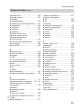
Index
Index
Installation instructions
Preparing for installation
Product information..............................................................................................
General information - electrical connection..........................................................
Installation............................................................................................................
Overview of possible system schemes................................................................
Function description for the system examples.....................................................
Primary circuit, type BW (brine/water)..................................................................
Primary circuit, type WW (water/water)................................................................
Primary circuit, type BW + BWS (two-stage version)...........................................
Primary circuit, type WW + WWS (two-stage version).........................................
Integration of the two-stage version in the system examples...............................
System example 1................................................................................................
System example 2................................................................................................
DHW heating........................................................................................................
9
10
10
15
17
22
24
27
31
39
44
52
65
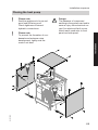
Installation sequence
Installing the heat pump....................................................................................... 67
Hydraulic connections.......................................................................................... 70
Electrical connections........................................................................................... 72
Power supply........................................................................................................ 103
Connecting to terminals X3.8/X3.9....................................................................... 114
Closing the heat pump......................................................................................... 115
Checking grommets............................................................................................. 116
Service instructions
Commissioning, inspection, maintenance
Steps - commissioning, inspection and maintenance.......................................... 118
Further details regarding the individual steps....................................................... 119
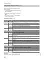
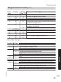
Troubleshooting
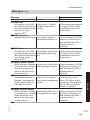
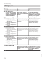
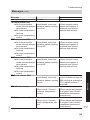
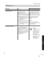
Messages............................................................................................................. 126
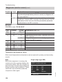
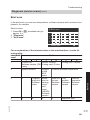
Diagnosis (service scans).................................................................................... 150
Testing outputs (actuator test).............................................................................. 162
Function check..................................................................................................... 163
Steps if the room temperature is too low.............................................................. 164
No display indication on the programming unit.................................................... 164
Repairs................................................................................................................. 165
5442 829 GB
Control unit settings by the contractor............................................................ 171
4
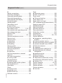
Index
Index
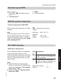
Parameter group system definition
Parameter group system definition....................................................................... 173
7000 System scheme........................................................................................... 173
7001 Language.................................................................................................... 173
7003 Temperature differential for the heating limit............................................... 174
7004 Temperature differential for the cooling limit............................................... 174
7010 External extension....................................................................................... 175
7008 Swimming pool............................................................................................ 176
700A Cascade...................................................................................................... 176
5735 Number of lag heat pumps.......................................................................... 176
700B Output of lag heat pumps............................................................................ 177
7011 External operating status changeover......................................................... 177
7012 Operating status for external changeover................................................... 179
701A Pumps and compressor, external blocking................................................. 180
7013 Duration of external operating status changeover...................................... 181
7014 External demand mixer "OPEN".................................................................. 182
7015 External blocking mixer "CLOSED"............................................................. 183
7017 Vitocom 100................................................................................................ 184
701B Common system temperature sensor......................................................... 184
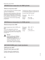
Parameter group compressor
Parameter group compressor............................................................................... 185
5000 Enable compressor..................................................................................... 185
5030 Heat pump output........................................................................................ 185
Parameter group compressor 2
Parameter group compressor 2............................................................................ 186
5100 Enabling heat pump stage 2........................................................................ 186
5130 Heat pump output........................................................................................ 186
5442 829 GB
Parameter group external heat source
Parameter group external heat source................................................................. 187
7B00 Enabling an external heat source............................................................... 187
7B01 Priority of external heat sources................................................................. 187
7B02 Dual-mode temperature of external heat sources....................................... 188
7B0D External heat source for DHW.................................................................... 188
Parameter group DHW
Parameter group DHW......................................................................................... 189
6000 Set cylinder temperature............................................................................. 189
6015 DHW reheating............................................................................................ 189
6005 Minimum temperature for DHW cylinder..................................................... 190
6006 Maximum temperature for DHW cylinder.................................................... 190
5
Index
Index
6007/6008 DHW/booster heater hysteresis......................................................... 190
6009 DHW start optimisation................................................................................ 191
600A DHW stop optimisation............................................................................... 192
600C Set DHW temperature 2............................................................................. 192
600E Temperature sensor 2................................................................................. 192
6016 DHW heating priority................................................................................... 192
6017 DHW at control high pressure..................................................................... 193
6020 Cylinder primary pump operating mode...................................................... 193
Parameter group solar
Parameter group solar.......................................................................................... 195
7A00 Solar control unit......................................................................................... 195
Parameter group electric heater
Parameter group electric heater........................................................................... 196
7900 Instantaneous heating water heater (on site).............................................. 196
7902 Heating mode with booster heater.............................................................. 197
7907 Max. stage instantaneous heating water heater......................................... 197
790A Stage at power-OFF................................................................................... 197
790B Dual-mode temperature instantaneous heating water heater..................... 198
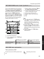
Parameter group internal hydraulics
Parameter group internal hydraulics.................................................................... 199
7300 Heat pump for drying a building.................................................................. 199
7303 Screed program .......................................................................................... 199
730D 3-way diverter valve mode.......................................................................... 201
730C Set flow temperature, external demand...................................................... 202
7320 Primary pump operating mode.................................................................... 202
7340 Secondary pump operating mode............................................................... 203
Parameter group heating circuits/cooling circuit
Parameter group heating circuits......................................................................... 207
2000/2001/2022 Room temperatures and switching times.................................. 207
2003 Enabling the remote control........................................................................ 207
2006/2007 Heating curve slope/level................................................................... 208
6
5442 829 GB
Parameter group buffer cylinder
Parameter group heating water buffer cylinder.................................................... 204
7200 Heating water buffer cylinder....................................................................... 204
7202 Set temperature for "Fixed val.".................................................................. 204
7203 Hysteresis.................................................................................................... 204
7204 Maximum temperature................................................................................ 205
7208 Dual-mode temperature, heating water buffer cylinder............................... 206
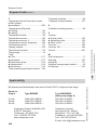
Index
Index
200A Influence of room temperature hook-up...................................................... 208
200B Room temperature hook-up (heating circuits)............................................. 209
200E Maximum set flow temperature................................................................... 209
Parameter group cooling
Parameter group cooling...................................................................................... 211
7100 Cooling mode.............................................................................................. 211
7101 Cooling circuit.............................................................................................. 212
7102 Room temperature separate cooling circuit................................................. 212
7103 Minimum flow temperature for separate cooling circuit............................... 212
7104 Room hook-up cooling circuit...................................................................... 213
7110/7111 Cooling curve (cooling circuit/separate cooling circuit)...................... 213
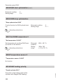
Parameter group time
Parameter group time........................................................................................... 214
7C00 - 7C06 Summertime/wintertime.................................................................. 214
Parameter group communication
Parameter group communication......................................................................... 215
7710 LON communication module....................................................................... 215
7798/7777 LON system number/subscriber number............................................ 215
7779 Fault manager............................................................................................. 216
779C Receive interval for data............................................................................. 216
7797 Outside temperature via LON...................................................................... 217
77FF Time via LON.............................................................................................. 217
5707 Heat pump numbers in a cascade............................................................... 218
Parameter group operation
Parameter group operation.................................................................................. 219
8800 Lock out controls......................................................................................... 219
Connection and wiring diagrams
Overview of the PCBs and connection options.................................................... 220
Parts lists
Parts list................................................................................................................ 231
5442 829 GB
Commissioning/service reports
Hydraulic parameters report................................................................................. 236
Control parameters report.................................................................................... 236
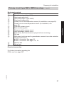
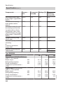
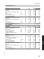
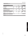
Specification....................................................................................................... 241
7
Index
Index (cont.)
Appendix
Heat pump commissioning order.......................................................................... 246
Certificates
Declaration of conformity...................................................................................... 247
5442 829 GB
Keyword index.................................................................................................... 248
8
Preparing for installation
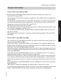
Product information
Brine/water or water/water heat pump with electronic heat pump control unit
Vitotronic 200, type WO1A
The refrigerant circuit has an electronic expansion valve (EEV) with an independent
control circuit.
For type WW, a separate well circuit provides the primary circuit with heating energy
via a separating heat exchanger (accessory). The well circuit is also controlled by
heat pump control unit Vitotronic 200, type WO1A.
All sensors are fitted inside sensor wells.
The heat pump control unit can activate and control a heating circuit provided on site
for cooling or a separate cooling circuit.
For central and DHW heating, an instantaneous heating water heater (on site) can
also be controlled.
The output can be extended in conjunction with heat pump stage 2 (Vitocal 300-G,
type BWS).
Vitocal 300-G, type BWS and WWS
5442 829 GB
The Vitocal 300-G, type BWS and WWS, are used to extend the output (stage 2) of
heat pumps type BW and WW.
Heat pump stage 2 (type BWS/WWS) can be used both for heating operation and
DHW heating. Accordingly, a second secondary pump or circulation pump for cylinder
heating (on the heating water side) is required.
Heat pump stage 2 (type BWS/WWS) does not have its own heat pump control unit
and is controlled by the heat pump control unit Vitotronic 200, type WO1A of the heat
pump (type BW/WW).
Heat pump stage 2 (type BWS/WWS) has its own refrigerant circuit. This means a
separate power supply is required for every compressor.
With the two-stage version, either a primary pump can be used for every heat pump,
or a common external primary pump can be used. Independently, a collective flow
and return temperature sensor is used on the primary side at the common flow and
return.
Heat pump stage 2 (type BWS/WWS) must be installed to the left of the heat pump
(type BW/WW).
The hydraulic connection between two heat pumps is carried out on site.
An instantaneous heating water heater (on site) can only be controlled by heat pump
stage 1 (type BW/WW) (for heat pump cascades only by the lead appliance).
9
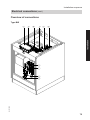
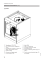
Installation
Vitocal 300-G, Type BW and WW
Preparing for installation
General information - electrical connection
■ The total output of all components connected directly to the heat pump control unit (e.g. pumps, valves, message
facilities, contactors) must not exceed
1000 W.
If the total load ≤ 1000 W, the individual rating of a component (e.g. pump,
valve, message facility, contactor) can
be greater than specified (observe
max. contact load; see also
page 241).
■ If the compressor and/or instantaneous heating water heater (on site) are
operated at a lower tariff (power-OFF),
provide an additional cable for the
power-OFF signal (e.g.
NYM 3 x 1.5 mm2) from the distribution
board (meter box) to the heat pump
control unit (see page 104).
■ The number of power cables from the
distribution board (meter box) to the
heat pump control unit depends on the
system version and tariffs used (see
from page 103).
■ The cores of the KM BUS cable are
interchangeable.
For further information, see heat pump
control unit and power supply
(page 103).
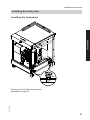
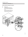
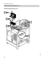
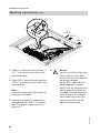
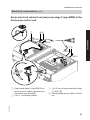
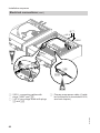
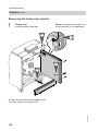
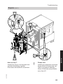
Installation
For handling purposes, the heat pump
module can be removed (see
page 168).
!
!
Please note
Avoid damaging the appliance
during handling.
Never put weight on top of the
appliance.
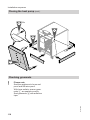
Please note
If the compressor is at a steep
angle in the heat pump, lubricant
will enter the refrigerant circuit
and damage the appliance.
Max. tilting angle 45°.
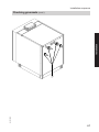
Installation room requirements
10
Please note
The installation room must be dry
and free from the risk of frost.
Ensure ambient temperatures of
0 to 35 ºC.
!
Please note
Avoid risk of explosion due to
dust, gases and vapours
in the installation room.
5442 829 GB
!
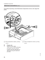
Preparing for installation
Installation (cont.)
Please note
Observe the permissible floor
load.
■ Total weight
BW 121
282 kg
BWS 121
277 kg
BW 129
305 kg
BWS 129
300 kg
BW 145
345 kg
BWS 145
340 kg
■ To prevent structure-borne noise,
never set up the appliance on ceilings
with wooden joists (e.g. in the attic).
■ Level the appliance.
If the adjustable feet are used to compensate for an uneven floor (max.
10 mm), the pressure load on the feet
must be distributed evenly.
■ Observe the required floor area and
minimum room volume (as per
DIN EN 378):
Type
Floor
area
BW/BWS
121
BW/BWS
129
BW/BWS
145
5 m2
Min. space
requirement
14 m3
7 m2
17 m3
9 m2
123 m3
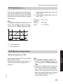
■ Observe required minimum clearances:
Single stage (type BW)
A
≥ 400
≥ 1500
≥ 400
5442 829 GB
A Clearance depends on on-site
installation and location
11
Installation
!
Preparing for installation
Installation (cont.)
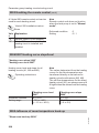
Two stage (type BW/BWS)
A
≥ 400
= 300
≥ 1500
≥ 400
5442 829 GB
A Clearance depends on on-site
installation and location
12
Preparing for installation
Installation (cont.)
Requirements - on-site connections
Single stage (type BW)
Installation
5442 829 GB
1315
400 V
< 42 V
301
230 V
100
86
171
88
230
720
540
270
13
Preparing for installation
Installation (cont.)
Two stage (type BW/BWS)
230 V
400 V
< 42 V
1315
400 V
< 42 V
100
301
230 V
230
100
720
540
270
86
88
171
230
720
540
270
= 300
5442 829 GB
■ Install hydraulic connections on site
stress-free.
■ Establish hydraulic connections
between the two heat pumps (type
BW/BWS) on site.
■ All required components (with a suitably designed plate heat exchanger) for
the cooling circuit must be provided on
site.
14
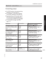
Preparing for installation
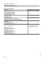
Installation (cont.)
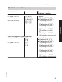
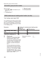
Recommended power cables:
Type
Heat pump control unit (230 V~)
BW 121
3 x 1.5 mm2
BWS 121
—
BW 129
3 x 1.5 mm2
BWS 129
—
BW 145
3 x 1.5 mm2
BWS 145
—
BWS
A connecting cable is used
for the power supply
1.0 m
Connecting cable
Compressor (400 V~)
Max. cable length
50 m
4 x 2.5 mm2
50 m
4 x 2.5 mm2
50 m
4 x 4.0 mm2
50 m
4 x 4.0 mm2
40 m
4 x 6.0 mm2
40 m
4 x 6.0 mm2
Note
An instantaneous heating water heater
(on site) can only be installed outside
the heat pump (on site). The flow temperature sensor system must be installed in the direction of flow downstream of
the instantaneous heating water heater.
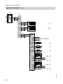
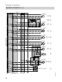
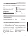
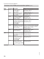
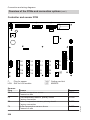
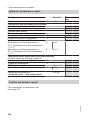
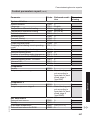
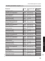
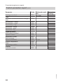
Overview of possible system schemes
5442 829 GB
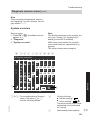
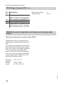
The following table provides an overview
of all possible system schemes.
15
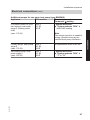
Installation
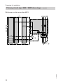
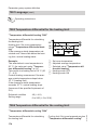
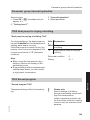
Line lengths in the heat pump plus wall clearance:
Type
BW
Heat pump control unit
1.0 m
power supply (230 V~)
Compressor power supply 1.0 m
(400 V~)
Additional power cables
1.5 m
Preparing for installation
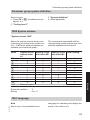
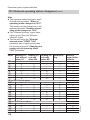
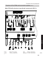
Overview of possible system schemes (cont.)
Heating circuit
A1
M2
M3
DHW cylinder
Heating
water buffer
cylinder
External
heat source
Cooling
mode (only
one "cooling circuit"
possible)
Heating circuit
A1
M2
M3
Separate
cooling circuit
Swimming
pool
Solar thermal system
(only with
Vitosolic
100/200)
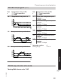
System diagram (ID 7000)
0
1
2
3
4
5
6
7
8
9
10
11
–
–
–
X
X
–
–
–
X
–
–
X
–
X
–
–
–
X
–
X
X
X
–
–
X
X
–
X
–
X
X
–
–
X
X
X
X
X
X
—
X
X
X
X
–
–
–
–
–
0
0
X
X
X
X
X
X
X
X
–
–
0*1
0*1
0
0
0
0
0
0
0
0
–
–
–
–
0
0
–
–
0
0
–
–
0
–
0
–
0
–
0
–
0
0
0
–
0
0
0
–
0
–
0
0
0
–
0
0
0
0
0
0
0
0
0
0
0
–
–
–
–
0
0
0
0
0
0
0
0
0
0
0
–
0
–
0
–
0
–
0
–
0
–
0
–
*1
Only in conjunction with a heating water buffer cylinder.
16
5442 829 GB
X Requirement
0 Option
Preparing for installation
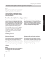
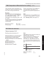
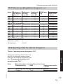
Function description for the system examples
Note
The system examples are recommendations only, which must be checked on
site for completeness and function.
Please observe the applicable regulations and directives for design, installation and operation.
For reasons of modularity, compressor
stage 2 refers to a separate heat pump
stage 2 (type BWS). Heat pump stage 2
is not equipped with its own heat pump
control unit, but with its own EEV controller to regulate the cooling circuit.
If the heating output required is greater
than that of the heat pump (type BW,
compressor stage 1), the heat pump
control unit starts heat pump stage 2
(type BWS).
For optimised starting and stopping of
heat pump stage 2, the heating outputs
of the two compressor stages must be
known. This is specified with parameter
"Output compressor stage 5030".
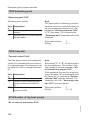
Heating circuit
Minimum flow rate
Systems with small water volumes
Heat pumps require a minimum heating
water flow rate (see specification on
page 242), which must be maintained.
To ensure the minimum flow rate, install
an overflow valve (or low loss header) in
systems without a heating water buffer
cylinder.
For systems with small water volumes
(for example, heating systems with radiators), use a heating water buffer cylinder to prevent excessive heat pump
cycling (starting/stopping).
5442 829 GB
Note
A minimum flow rate is also required on
the primary side (see specification,
page 242).
17
Installation
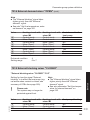
Function description two-stage version
Preparing for installation
Function description for the system examples (cont.)
Systems with large water volumes
Systems with large water volumes (for
example, underfloor heating systems)
can operate without a heating water buffer cylinder. In these heating systems,
install an overflow valve at the heating
circuit distributor of the underfloor heating system that is furthest away from the
heat pump. This safeguards the minimum flow rate, even in sealed heating
circuits.
In conjunction with an underfloor heating
system, install a temperature limiter
(accessory, order no. 7151 728 or
7151 729) (for connection, see
page 88).
Heating water buffer cylinder operated in parallel
Note
The flow rate of the secondary pump
should be greater than that of the heating
circuit pumps.
Protect the heat pump in accordance
with EN 12828 [or local regulations].
Systems without heating water buffer
cylinder
To safeguard the minimum heating
water flow rate (see specification from
page 242), do not install a mixer in the
heating circuit.
Low loss header
When using a low loss header, ensure
that the flow rate on the heating circuit
side is greater than the flow rate on the
secondary side of the heat pump.
The heat pump control unit treats a low
loss header like a small heating water
buffer cylinder. The low loss header must
therefore be configured as a heating
water buffer cylinder in the control unit
settings (see from page 204).
5442 829 GB
Applications for a heating water buffer
cylinder:
■ Bridging power-OFF periods:
At peak times, heat pumps may be
switched off by your local power supply utility, subject to your electricity tariff. A heating water buffer cylinder supplies the heating circuits even during
this power-OFF period.
■ Constant flow rate through the heat
pump:
Heating water buffer cylinders provide
hydraulic separation of the flow in the
secondary and heating circuits. For
example, the flow rate in the secondary circuit remains constant even if
the heating circuit flow rate is reduced
via thermostatic valves.
■ Longer heat pump operating times
Because of the increased water volume
of the heat source and the fact that it may
have a separate shut-off facility, an additional (or larger) expansion vessel
should be provided.
18
Preparing for installation
Function description for the system examples (cont.)
Cooling operation
Types and configuration
Subject to system version, natural cooling, optionally with or without a mixer, or
active cooling are possible. For natural
cooling, the compressor is shut down
and heat exchange occurs directly with
the primary circuit. Active cooling uses
the heat pump as a refrigeration unit,
meaning a higher cooling capacity is
possible than with natural cooling.
Parameter "Cooling 7100" specifies the
type of cooling mode. Active cooling is
only possible outside a power-OFF
period, and must be enabled separately
by the system operator.
Enabling cooling mode
Operating instructions
5442 829 GB
Even if active cooling is selected and
enabled, the control unit will initially start
the natural cooling function. If the set
room temperature cannot be achieved
with this function, the compressor
starts.
A mixer can only be used with natural
cooling, and particularly in cooling mode
on underfloor heating circuits, it keeps
the flow temperature above the dew
point. To ensure the transfer of the high
cooling output in active cooling at all
times, no mixer is provided.
Operating status
Cooling mode in the heating circuits is
carried out in "Normal" and "Fixed val."
operating statuses. The separate cooling circuit is additionally cooled in
"Reduced" and "Only DHW" operating
statuses. The latter enables continuous
cooling of a room, e.g. a warehouse during the summer months.
The cooling output is subject to either
weather-compensated control according
to the heating or cooling curve, or room
temperature-dependent control.
Note
For cooling operation in the following
cases, a room temperature sensor must
be installed and enabled (parameter
"Remote control 2003" set to "1"):
■ Weather-compensated cooling mode
with room influence
■ Room temperature-dependent cooling
mode
■ "Active cooling"
A room temperature sensor must always
be installed for a separate cooling circuit.
Weather-compensated control
In weather-compensated cooling mode,
the set flow temperature is calculated
from the relevant set room temperature
and the current outside temperature
(long-term average) according to the
cooling curve. Its level ("Cooling curve
level 7110") and slope ("Cooling curve
slope 7111") are adjustable.
Room influence
19
Installation
Cooling mode is possible either with one
of the available heating circuits, or with a
separate cooling circuit (e.g. chilled ceilings or fan convectors).
Preparing for installation
Function description for the system examples (cont.)
Parameter "Slope room hook-up
7104" specifies the strength of the room
influence for cooling mode.
Operating status "Normal"
Operating status "Fixed val."
In operating status "Fixed val.", cooling
occurs at the min. flow temperature
"Minimum flow temperature 7103".
The cooling output for the heating circuits is subject to either weather-compensated control according to the cooling curve, or room temperature-dependent control.
DHW heating
In the delivered condition, DHW heating
by the heat pump takes priority over the
heating circuits.
The heat pump control unit switches the
DHW circulation pump ("DHW circ time
prog") off during cylinder heating to prevent cylinder heating from being
impaired.
Available booster heaters to reheat the
DHW:
■ External heat source
■ Instantaneous heating water heater
(on site)
The integral load manager in the heat
pump control unit decides which heat
sources to use for DHW heating. Generally the external heat source has priority
over the instantaneous heating water
heater (on site).
If one of the following criteria is met, the
booster heaters begin cylinder heating:
■ Cylinder temperature is below 3 °C
(frost protection).
■ Heat pump does not provide any heating output and actual temperature has
fallen below set temperature at the top
cylinder temperature sensor by more
than "Booster heater hysteresis
6008".
Note
The external heat source switches off as
soon as the set value is reached at the
top temperature sensor minus a hysteresis of 1 K.
Instantaneous heating water heater (on site)
20
Installation instructions, instantaneous heating water heater
5442 829 GB
An electric instantaneous heating water
heater can be integrated in the heating
water flow as an auxiliary heat source.
Preparing for installation
The heat pump control unit regulates this
function ("Inst. heating water heater
7900"). The instantaneous heating
water heater can be enabled separately
for central heating ("Heating with electro 7902") and DHW heating ("DHW
with e heating 6015").
If enabled via parameter "Maximum
stage, electric heating 7907", the heat
pump control unit starts stages 1, 2 or 3
of the instantaneous heating water
heater, subject to heat demand. As soon
as the maximum flow temperature in the
secondary circuit "Maximum flow temperature 200E" is reached, the heat
pump control unit switches the instantaneous heating water heater off.
Parameter "Stage at power-OFF
790A" restricts the output stage of the
instantaneous heating water heater for
the duration of the power-OFF period.
To limit the total power consumption, the
heat pump control unit stops the instantaneous heating water heater for a few
seconds directly before the compressor
starts. Each stage is subsequently started individually one after the other in
intervals of 10 s.
If the instantaneous heating water heater
is on and the differential between flow
and return temperatures in the secondary circuit does not rise by at least 1 K
within 24 h, the heat pump control unit
displays a fault message.
External heat source
5442 829 GB
The heat pump control unit enables the
heat pump to operate in dual mode with
an external heat source, e.g. oil boiler
("External heat source 7B00").
The external heat source is hydraulically
connected to let the heat pump also be
used as a return temperature raising
facility for the boiler. System separation
is provided either with a low loss header
or heating water buffer cylinder.
For optimum heat pump operation, the
external heat source must be integrated
via a mixer into the heating water flow. A
quick reaction is achieved by directly
controlling this mixer via the heat pump
control unit.
If the outside temperature (long-term
average) is below the "Dual-mode temperature 7B02", the heat pump control
unit starts the external heat source. In
case of direct heat demand from the consumers (e.g. for frost protection or if the
heat pump is faulty), the external heat
source is also started above the dual
mode temperature.
In addition, the external heat source can
be enabled for DHW heating ("External
heat source for DHW 7B0D").
Note
The heat pump control unit does not
contain any safety function for the external heat source. To prevent excessive
temperatures in the heat pump flow and
return in case of a fault, high limit safety
cut-outs must be provided to shut down
the external heat source and the secondary pump(s) (switching threshold in
each case 70 °C).
21
Installation
Function description for the system examples (cont.)
Preparing for installation
Function description for the system examples (cont.)
Power-OFF
It is possible for the power supply utility
to shut down the compressor and instantaneous heating water heater (see from
page 108). The ability to carry out such
a shutdown may be a power supply utility
requirement for providing a lower tariff.
This must not shut down the power supply to the heat pump control unit.
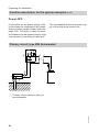
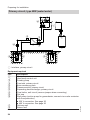
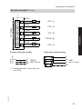
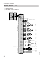
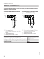
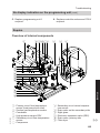
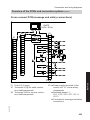
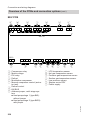
Primary circuit, type BW (brine/water)
wQ
wP
P
P
P
qT
2
wW
1
wU
5442 829 GB
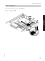
P Primary circuit interface (see system examples)
22
Preparing for installation
Primary circuit, type BW (brine/water) (cont.)
Required Equipment
Pos.
Description
Heat pump
1
Heat pump control unit
2
Primary pump
qT
Brine accessory pack
wP
Pressure switch, primary circuit
wQ
Brine distributor for geothermal probes/collectors
wW
Geothermal probes/collectors
wU
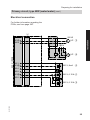
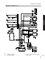
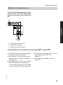
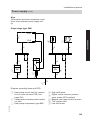
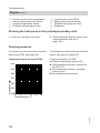
Installation
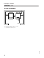
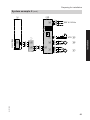
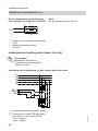
Electrical connection
For further information regarding the
PCBs, see from page 220.
2
200 W
230 V / 50 Hz
.
sYYA
M
1~ UP qT
X1.?
X2.N
X3.9
X1.?
P
230 V; 0.15 A wQ
5442 829 GB
X3.8
23
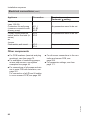
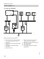
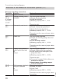
Preparing for installation
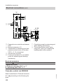
Primary circuit, type WW (water/water)
wQ
wP
P
P
P
wE
wR
qT
wW
2
qO
1
wZ
wU
wI
Equipment required
Pos.
Description
Heat pump
1
Heat pump control unit
2
Primary pump
qT
Frost stat, primary circuit
qO
Brine accessory pack
wP
Pressure switch, primary circuit
wQ
Separating heat exchanger, primary circuit
wW
Flow limiter, well circuit (remove jumper when connecting)
wE
Dirt trap
wR
Well pump (suction pump for groundwater; connect via on-site contactor
wZ
with fuse protection)
■ 230 V connection: See page 25
■ 400 V connection: See page 26
Delivery well
wU
Return well
wI
24
5442 829 GB
P Interface, primary circuit
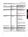
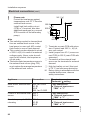
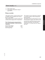
Preparing for installation
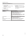
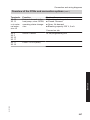
Primary circuit, type WW (water/water) (cont.)
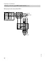
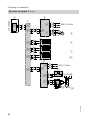
Electrical connection
For further information regarding the
PCBs, see from page 220.
2
200 W
.
sYYA
Installation
M
1~ UP qT
X1.?
X2.N
L1 ? N
230 V / 50 Hz
K1
X3.3
X1.?
M
1~ UP wZ
´
230 V; 2mA wE
P
230 V; 0.15 A wQ
X3.4
X3.9
X1.?
X3.8
5442 829 GB
230 V; 0.15 A qO
25
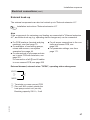
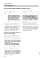
Preparing for installation
Primary circuit, type WW (water/water) (cont.)
Well pump on-site connection 400 V~
2
200 W
.
sYYA
M
1~ UP qT
X1.?
X2.N
L1 L2 L3 ?
K1
I>I>I>
5442 829 GB
M
3~ UP wZ
26
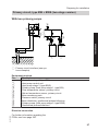
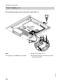
Preparing for installation
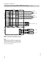
Primary circuit, type BW + BWS (two-stage version)
With two primary pumps
wQ
wP
P
qZ
P
P
wT
qT
Installation
qU
2
wW
9
1
wU
P Primary circuit interface (see system examples)
Equipment required
Pos.
Description
Heat pump stage 1 (type BW)
1
Heat pump control unit
2
Heat pump stage 2 (type BWS)
9
Primary pump (heat pump stage 1, type BW)
qT
Flow temperature sensor, primary circuit
qZ
Return temperature sensor, primary circuit
qU
Brine accessory pack
wP
Pressure switch, primary circuit
wQ
Brine distributor, geothermal probes/collectors
wW
Primary pump (heat pump stage 2, type BWS)
wT
Geothermal probes/collectors
wU
5442 829 GB
Electrical connection
For further information regarding the
PCBs, see from page 220.
27
Preparing for installation
Primary circuit, type BW + BWS (two-stage… (cont.)
2
200 W
230 V / 50 Hz
.
sYYA
M
1~ UP qT
X1.?
X2.N
200 W
.
sXVS
M
1~ UP wT
X1.?
X2.N
X3.9
X1.?
P
230 V; 0.15 A wQ
Low voltage
X3.8
X
[G
12
X
[G
13
Pt 500
qZ
Pt 500
qU
With a common primary pump
5442 829 GB
Note
If types BW and BWS are installed with
different rated outputs, the different flow
rates mean that two primary pumps must
be used (see page 27).
28
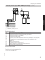
Preparing for installation
Primary circuit, type BW + BWS (two-stage… (cont.)
wQ
wP
P
qZ
P
P
qU
qT
Installation
2
wW
9
1
wU
P Interface, primary circuit
Equipment required
Pos.
Description
Heat pump stage 1 (type BW)
1
Heat pump control unit Vitotronic 200, type WO1A
2
Heat pump stage 2 (type BWS)
9
Common primary pump
qT
Primary circuit flow temperature sensor (for installation, see page 84)
qZ
Primary circuit return temperature sensor (for installation, see
qU
page 84)
Brine accessory pack
wP
Pressure switch, primary circuit
wQ
Brine distributor, geothermal probes/collectors
wW
Geothermal probes/collectors
wU
Electrical connection
5442 829 GB
For further information regarding the
PCBs, see from page 220.
29
Preparing for installation
Primary circuit, type BW + BWS (two-stage… (cont.)
2
.
sYYA
230 V / 50 Hz
.
sXVS
M
1~
X1.?
X2.N
200 W
UP qT
X3.9
X1.?
P
230 V; 0.15 AwQ
X
[G
12
X
[G
13
Pt 500
qZ
Pt 500
qU
5442 829 GB
Low voltage
X3.8
30
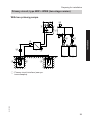
Preparing for installation
Primary circuit, type WW + WWS (two-stage version)
With two primary pumps
wQ
wP
P
qZ
P
P
qU
wT
qT
Installation
wE
2
wR
wW
qO
9
wZ
wU
1
wI
5442 829 GB
P Primary circuit interface (see system examples)
31
Preparing for installation
Primary circuit, type WW + WWS (two-stage… (cont.)
Equipment required
Pos.
Description
Heat pump stage 1 (type WW)
1
Heat pump control unit
2
Heat pump stage 2 (type WWS)
9
Primary pump (heat pump stage 1, type WW)
qT
Primary circuit flow temperature sensor (for installation, see page 84)
qZ
Primary circuit return temperature sensor (for installation, see
qU
page 84)
Frost stat, primary circuit
qO
Brine accessory pack
wP
Pressure switch, primary circuit
wQ
Heat exchanger, primary circuit
wW
Flow limiter, well circuit (remove jumper before connecting)
wE
Dirt trap
wR
Primary pump (heat pump stage 2, type WWS)
wT
Well pump (suction pump for groundwater; connect via on-site contactor
wZ
with fuse protection)
■ 230 V connection: See page 33
■ 400 V connection: See pages 38, 34.
Delivery well
wU
Return well
wI
Electrical connection
5442 829 GB
For further information regarding the
PCBs, see from page 220.
32
Preparing for installation
Primary circuit, type WW + WWS (two-stage… (cont.)
Well pump on-site connection 230 V~
2
200 W
M
1~ UP qT
200 W
.
sXVS
M
1~ UP wT
X1.?
X2.N
Installation
230 V / 50 Hz
.
sYYA
X1.?
X2.N
L1 ? N
X3.1
X2.N
K1
K2
K3
UP wZ
5442 829 GB
M
1~
33
Preparing for installation
Primary circuit, type WW + WWS (two-stage… (cont.)
Well pump on-site connection 400 V
2
200 W
230 V / 50 Hz
.
sYYA
M
1~ UP qT
X1.?
X2.N
200 W
.
sXVS
M
1~ UP wT
X1.?
X2.N
L1 L2 L3 ?
X3.1
X2.N
K1
K2
K3
I>I>I>
5442 829 GB
M
3~ UP wZ
34
Preparing for installation
Primary circuit, type WW + WWS (two-stage… (cont.)
Connecting the sensors and limiters
2
X1.?
X3.4
´
230 V; 2 mA wE
P
230 V; 0.15 A wQ
X3.8
X1.?
X3.9
Installation
230 V/50 Hz
X3.3
Low voltage
230 V; 0.15 A qO
X
[G
X
[G
12
13
Pt 500
qZ
Pt 500
qU
With a common primary pump
5442 829 GB
Note
If types WW and WWS are installed with
different rated outputs, the different flow
rates mean that two primary pumps must
be used (see page 31).
35
Preparing for installation
Primary circuit, type WW + WWS (two-stage… (cont.)
wQ
wP
qZ
P
P
P
qU
wE
wR
wZ
qT
wW
wU
2
qO
9
1
wI
5442 829 GB
P Interface, primary circuit
36
Preparing for installation
Equipment required
Pos.
Description
Heat pump stage 1 (type WW)
1
Heat pump control unit
2
Heat pump stage 2 (type WWS)
9
Common primary pump
qT
Primary circuit flow temperature sensor (for installation, see page 84)
qZ
Primary circuit return temperature sensor (for installation, see
qU
page 84)
Frost stat, primary circuit
qO
Brine accessory pack
wP
Pressure switch, primary circuit
wQ
Heat exchanger, primary circuit
wW
Flow limiter, well circuit (remove jumper before connecting)
wE
Dirt trap
wR
Well pump (suction pump for groundwater; connect via on-site contactor
wZ
with fuse protection)
■ 230 V connection: See page 33
■ 400 V connection: See pages 38, 34.
Delivery well
wU
Return well
wI
Electrical connection
5442 829 GB
For further information regarding the
PCBs, see from page 220.
37
Installation
Primary circuit, type WW + WWS (two-stage… (cont.)
Preparing for installation
Primary circuit, type WW + WWS (two-stage… (cont.)
Well pump on-site connection 400 V
2
L1L2L3 ?
230 V/50 Hz
.
sYYA
.
sXVS
X1.?
X2.N
M
1~
200 W
UPqT
I>I>I>
X2.N
5442 829 GB
M
3~ UP wZ
38
Preparing for installation
Primary circuit, type WW + WWS (two-stage… (cont.)
Connecting the sensors and limiters
2
´
230 V; 2 mA wE
P
230 V; 0.15 A wQ
X3.4
X3.8
X1.?
X3.9
Installation
230 V/50 Hz
X3.3
X1.?
Low voltage
230 V; 0.15 A qO
X
[G
X
[G
12
13
Pt 500
qZ
Pt 500
qU
5442 829 GB
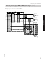
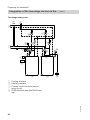
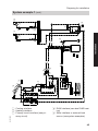
Integration of the two-stage version in the system examples
Note
■ Every partial scheme can be integrated into the system examples via the
interfaces indicated.
■ Connect return DHW cylinder only to
heat pump, type BW.
■ Two-stage heat pump cascade:
For the two-stage heat pump cascade,
the lead appliance and lag heat pumps
each comprise a heat pump (type BW)
and heat pump stage 2 (type BWS).
The electrical connection is made at
the heat pump (type BW) (via the KM
BUS at external extension H1) as per
page 100.
39
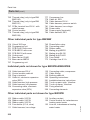
Preparing for installation
Integration of the two-stage version in the… (cont.)
Two-stage heat pump
C
H
W
6
qP
qZ
qQ
5
wT
qT
P
qU
3
2
qW
P
8
9
1
qE
5442 829 GB
C Cooling interface
H Heating interface
P Primary circuit interface (see primary circuit)
W DHW interface (see also DHW heating)
40
Preparing for installation
Integration of the two-stage version in the… (cont.)
1
2
9
II
1
9
5442 829 GB
C
H
P
Cooling interface
Heating interface
Primary circuit interface
9
3
P
H
W
C
qU
qZ
qP
wT
qQ
IV
1
3
2
6
qT
5
qU
qZ
qP
wT
III
1
3
2
qU
qT
5
9
wT
qQ
qZ
qP
6
qQ
Installation
3
2
6
qT
5
qU
qZ
qP
wT
I
qQ
6
qT
5
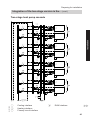
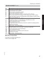
Two-stage heat pump cascade
W
DHW interface
41
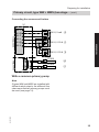
Preparing for installation
Integration of the two-stage version in the… (cont.)
I
Lead appliance (two-stage) of
the heat pump cascade
II to IV Lag heat pump (two-stage) 1 to
3
Equipment required
Pos.
Description
Heat source
Heat pump stage 1
1
Note
For recommended compressor power cable, see page 15, on-site fuse protection (see from page 104 and 242)
3
2
5
6
9
Outside temperature sensor
Heat pump control unit (for the power supply, use a 3 x 1.5 mm2 cable; onsite fuse protection ≤ 16 A)
Circulation pump for cylinder heating (heating water side), heat pump stage
1
Secondary pump, heat pump stage 1
Heat pump stage 2
Note
For recommended compressor power cable, see page 15, on-site fuse protection (see from page 104 and 242)
qP
qQ
qT
qZ
qU
wT
Secondary pump, heat pump stage 2
Circulation pump for cylinder heating (heating water side), heat pump stage
2
Primary pump, heat pump stage 1
Primary circuit flow temperature sensor (for installation, see page 84)
Primary circuit return temperature sensor (for installation, see page 84)
Primary pump, heat pump stage 2
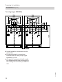
Electrical connection
5442 829 GB
For further information regarding the
PCBs, see from page 220.
42
Preparing for installation
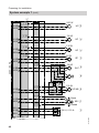
Integration of the two-stage version in the… (cont.)
2
130 W
.
sXVG
M
1~
X1.?
X2.N
130 W
.
sYYF
M
1~
X1.?
X2.N
UP 6
Installation
M
1~
X1.?
X2.N
200 W
.
sYYA
230 V / 50 Hz
UP 5
130 W
.
sYYS
M
1~
X1.?
X2.N
M
1~
X1.?
X2.N
12
X
[G
13
Ni 500
UP wT
130 W
M
1~
X1.?
X2.N
X
[G
UP qT
200 W
.
sXVS
.
sXVD
Low voltage
UP qQ
Pt 500
Pt 500
UP qP
qZ
qU
F0
F
[Ö
ATS 3
5442 829 GB
Required parameters
The additional parameters for the heat
pump cascade are set during commissioning by the certified heat pump contractor.
43
Preparing for installation
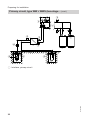
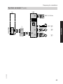
System example 1
■ Solar thermal system
■ Heating water buffer cylinder
Note
This scheme is a basic example without
shut-off valves or safety equipment. This
does not replace the local technical engineering task.
5442 829 GB
Select system scheme 8 (see
page 173)
■ Single stage heat pump, type BW
■ 1 underfloor heating circuit with mixer
(M2)
■ 1 radiator circuit with mixer (M3)
■ DHW heating with a cylinder primary
store
44
Preparing for installation
zT
zP
zU zQ
q-Z
q-U M
Installation
1
3
5442 829 GB
P
wU
wW
wP
eP
KW
P
wQ
eE
eQ X
rQ
rW
DHW
rE
rO
P
zZ
rR
rI
rT
eW
eU
rU
eZ M eT
eR
P
W
8
qT
5
2
6
P
qE
qW
H
zW
uE
uR
uZ
uU M
uP
uQ
q-T
q-E
q-P
q-Q
System example 1 (cont.)
C Cooling interface
H Heating interface
P Primary circuit interface (see primary circuit)
W DHW interface (see also DHW heating)
X Solar interface or external heat
source (see system examples)
45
Preparing for installation
System example 1 (cont.)
Pos.
1
2
3
5
6
8
qW
qE
qT
qZ
qU
wP
wQ
wW
wU
eP
eQ
eW
eE
eR
eT
eZ
eU
rQ
5442 829 GB
rW
rE
rR
rT
rU
rI
rO
Description
Heat source
Heat pump
Heat pump control unit
Outside temperature sensor
Circulation pump for cylinder heating (heating water side)
Secondary pump
KM BUS distributor
Safety equipment block with safety assembly
Expansion vessel
Primary circuit
Primary pump
Primary circuit flow temperature sensor (integrated into heat pump)
Primary circuit return temperature sensor (integrated into heat pump)
Brine accessory pack
Pressure switch, primary circuit
Brine distributor for geothermal probes/geothermal collectors
Geothermal probe/geothermal collector
DHW heating with a primary store system
DHW cylinder
Solar cylinder temperature sensor (connection S2 to Vitosolic)
Cylinder temperature sensor (connection to heat pump control unit)
Cylinder primary pump (DHW side)
Plate heat exchanger
Flow limiter
Motorised two-way valve, normally closed
DHW circulation pump
DHW heating with a solar thermal system
High limit safety cut-out for DHW cylinder to switch off the solar circuit pump
R1 rE
Solar-Divicon
Solar circuit pump R1
Collector temperature sensor (Vitosolic standard delivery, connection S1)
Solar collectors
Vitosolic 200 (observe separate installation instructions)
Safety equipment block with safety assembly
Expansion vessel
46
Preparing for installation
Pos.
zP
zQ
zW
zT
zZ
zU
uP
uQ
uE
uR
uZ
uU
q¢P
q¢Q
q¢E
q¢T
q¢Z
q¢U
Description
Heating water buffer cylinder
Heating water buffer cylinder
Buffer cylinder temperature sensor
System flow temperature sensor
Solar buffer temperature sensor (connection S4 to Vitosolic)
Solar circuit pump R4 for heating up the heating water buffer cylinder
High limit safety cut-out for heating water buffer cylinder to switch off the
solar circuit pump R4 zZ
Heating circuit with mixer (M2)
Underfloor heating circuit with directly controlled mixer motor
Vitotrol 200 remote control (accessory)
Flow temperature sensor
Temperature limiter as maximum limiter for underfloor heating systems
Heating circuit pump
Mixer motor - three-way mixer
Heating circuit with mixer (M3)
Radiator heating circuit with mixer, controlled via KM BUS
Vitotrol 200 remote control (accessory)
Flow temperature sensor
Extension kit for one heating circuit with mixer
Heating circuit pump
Mixer motor - three-way mixer
Electrical connection
5442 829 GB
For further information regarding the
PCBs, see from page 220.
47
Installation
System example 1 (cont.)
Preparing for installation
System example 1 (cont.)
2
200 W
.
sYYA
M
1~
X1.?
X2.N
130 W
.
sYYS
M
1~
X1.?
X2.N
M
1~
UP 5
50 W
.
sYXD
230 V / 50 Hz
UP 6
130 W
.
sYYF
X1.?
X2.N
M
1~
X1.?
X2.N
ZP eU
130 W
.
sXVH
X1.?
X2.N
sÖ
.
sXBA
M
1~
SLP eE
M
eZ
uR
100 W
M UP M2 uZ
1~
X1.?
X2.N
.
sXBD
Open
X1.?
X2.N
M
1~
.
sXBS
M2 uU
Closed
X3.9
X1.?
UP qT
P
230 V; 0.15 A
wQ
5442 829 GB
X3.8
48
Preparing for installation
System example 1 (cont.)
q-T
fÖ
1234
23
1
2
1
2
3
aVG
aVG
1
2
3
1
2
3
aVG
?
1
2
sÖ
L
?
N
gS
?
N
VTS q-E
M
1~
q-Z
M
1~
q-U
5442 829 GB
Low voltage
78
8
aVG
230 V / 50 Hz
456
S1
9 01
on
off
L
?
N
Installation
2
49
Preparing for installation
System example 1 (cont.)
2
Low voltage
8
aVG
1
2
1
2
3
aVG
1
2
3
on
off
aVG
1
2
3
on
off
aVG
1
2
3
aVG
uQ
1234
q-Q
1234
rU
145
L
?
N
L
? 230 V/50 Hz
N
S1
GND
S1
rR
S2
GND
S2
eQ
S4
GND
S4
zT
STB rQ
R1
?
N
M
1~
R4
?
N
M
1~
UP rE
STB zU
5442 829 GB
UP zZ
50
Preparing for installation
System example 1 (cont.)
2
Ni 500
ATS 3
F
[Ö
Pt 500
PTS zQ
Pt 500
STS eW
F
[H
Ni 500
Installation
Low voltage
F
[F
VTS M2 uE
F
[YS
Pt 500
VTS zW
F
[YD
Control unit power supply
A
X3.18
X2.1
X1.1
L1
1/N/PE
N
230 V/ 50 Hz
?
Compressor power supply
L1
L2 3/PE
L3 400 V, 50 Hz
PE
5442 829 GB
A Mains terminals on the cross connect PCB
51
Preparing for installation
System example 1 (cont.)
Required parameters
Parameter
"System definition"
■ "System scheme 7000"
"Solar"
■ "Solar control unit type 7A00"
Setting
"8"
"2"
Note
Vitosolic parameters must be set (see Vitosolic installation and service instructions)
For accessories (if installed):
DHW circulation pump
"Heating circuit 2"
■ "Remote control 3003"
"Heating circuit 3"
■ "Remote control 4003"
Set switching times (see
operating instructions)
"1"
"1"
System example 2
■ Heating water buffer cylinder
■ Cooling function "natural cooling" (on
site) at heating circuit M2
■ Swimming pool
Note
This scheme is a basic example without
shut-off valves or safety equipment. This
does not replace the local technical engineering task.
5442 829 GB
Select system scheme 10 (see
page 173)
■ Two stage heat pump type BW/BWS
■ 2 primary pumps
■ 1 heating circuit without mixer (A1)
■ 2 heating circuits with mixer (M2, M3)
■ External heat source for heating and
DHW
■ DHW heating with a cylinder primary
store
■ Solar thermal system
52
5442 829 GB
C Cooling interface
H Heating interface
wU
wW
wP
eP
DHW
KW
P
X
eW
eU
P
wQ
eE
eZ M eT
eR
C
qU
8
3
P
qZ
W
wT
9
qQ
iU
qP
qT
1
2
5
iO
M
iT M iR
iI
6
zW
iZ
qE
P
qW
H
uU M
uZ
uE
uR
iE φ
iW
M
M
1~
tR
oZ
oP
M
1~
Installation
tP
tE
tW tQ
iQ
uP
uQ
zP
qYT
q-Z
q-U M
q-T
q-E
oQ
tT
qR
zQ
q-P
qYQ
q-Q
qYW
qYE
qYP
qYR
Preparing for installation
System example 2 (cont.)
P Primary circuit interface (see primary circuit)
53
Preparing for installation
System example 2 (cont.)
W DHW interface (see also DHW heating)
X Solar interface or external heat
source (see system examples)
Pos.
1
2
3
5
6
8
9
qP
qQ
qW
qE
qT
qZ
qU
5442 829 GB
wT
wP
wQ
wW
wU
Description
Heat source
Heat pump stage 1 (type BW)
Heat pump control unit
Outside temperature sensor
Circulation pump for cylinder heating (heating water side) for heat pump
stage 1 (type BW)
Secondary pump for heat pump stage 1 (type BW)
KM BUS distributor
Heat pump stage 2 (BWS)
Secondary pump for heat pump stage 2 (type BWS)
Circulation pump for cylinder heating (heating water side) for heat pump
stage 2 (type BWS)
Safety equipment block with safety assembly
Expansion vessel
Primary circuit
Primary pump for heat pump stage 1 (type BW)
Primary circuit flow temperature sensor (installation only required for two
stage heat pump, see page 84)
Primary circuit return temperature sensor (installation only required for two
stage heat pump, see page 84)
Primary pump for heat pump stage 2 (type BWS)
Brine accessory pack
Pressure switch, primary circuit
Brine distributor for geothermal probes/geothermal collectors
Geothermal probe/geothermal collector
54
Preparing for installation
Pos.
eP
eW
eE
eR
eT
eZ
eU
qR
tP
tQ
tW
tE
tR
tT
5442 829 GB
zP
zQ
zW
Description
DHW heating with a primary store system
DHW cylinder
Cylinder temperature sensor
Cylinder primary pump (DHW side)
Plate heat exchanger
Flow limiter
Motorised two-way valve, normally closed
DHW circulation pump
External heat source
High limit safety cut-out (STB) to switch off the secondary pumps 6 and
qP
External heat source, e.g. oil boiler
External heat source demand (connection to external heat source)
Circulation pump for cylinder reheating
Boiler water temperature sensor (connection to heat pump control unit)
Directly controlled mixer motor
High limit safety cut-out 70 °C for shutting down the external heat source
(on site)
Heating water buffer cylinder
Heating water buffer cylinder
Buffer cylinder temperature sensor
System flow temperature sensor
55
Installation
System example 2 (cont.)
Preparing for installation
System example 2 (cont.)
Pos.
Description
Natural cooling function (NC)
Note
All required components (with a suitably designed plate heat exchanger)
for the cooling circuit must be provided on site.
iQ
Three-way diverter valve
Note
When using a three-way diverter valve without spring-loaded return, at
contact gS2 (from pos. iU) "L1" must be connected (see for example
terminal strip X3, page 225).
iW
iE
iR
iT
iZ
iU
iI
iO
Secondary cooling circuit pump
Contact humidistat
Primary cooling circuit pump
Mixer motor - three-way mixer
Frost stat
Extension kit for NC
Extension kit for heating circuit (cooling circuit) with mixer
Motorised two-way valve, normally closed
Note
When using a two-way diverter valve without spring-loaded return, at contact gS1 (from pos. iU) "L1" must be connected (see for example terminal
strip X3, page 225).
oP
oQ
oZ
5442 829 GB
uP
uQ
uE
uR
uZ
uU
Heating circuit without mixer (A1)
Radiator heating circuit
Vitotrol 200 remote control
Heating circuit pump
Heating circuit with mixer (M2)
Underfloor heating circuit with directly controlled mixer motor
Vitotrol 200 remote control (accessory)
Flow temperature sensor
Temperature limiter as maximum limiter for underfloor heating systems
Heating circuit pump
Mixer motor - three-way mixer
56
Preparing for installation
Pos.
q¢P
q¢Q
q¢E
q¢T
q¢Z
q¢U
qYP
qYQ
qYW
qYE
qYR
qYT
Description
Heating circuit with mixer (M3)
Radiator heating circuit with mixer, controlled via KM BUS
Vitotrol 200 remote control (accessory)
Flow temperature sensor
Extension kit for one heating circuit with mixer
Heating circuit pump
Mixer motor - three-way mixer
Swimming pool
Swimming pool
Thermostat for controlling the swimming pool temperature
Circulation pump for swimming pool heating
Plate heat exchanger
External extension H1 (only 1 external extension H1 can be connected to
the heat pump)
Three-way diverter valve (zero volt: Heating the heating water buffer cylinder)
Note
The additional parameters for two-stage
operation are set during commissioning
by the certified heat pump contractor.
Electrical connection
5442 829 GB
For further information regarding the
PCBs, see from page 220.
57
Installation
System example 2 (cont.)
Preparing for installation
System example 2 (cont.)
2
200 W
.
sYYA
M
1~
X1.?
X2.N
UP qT
STB qR
70 °C
.
sYYS
130 W
M
1~
X1.?
X2.N
130 W
.
sYYF
M
1~
X1.?
X2.N
UP 5
100 W
.
sYXS
230 V / 50 Hz
UP 6
M
1~
X1.?
X2.N
UP A1 oZ
50 W
.
sYXD
M
1~
X1.?
X2.N
ZP eU
130 W
.
sXVH
X1.?
X2.N
sÖ
.
sXBA
M
1~
SLP eE
M
eZ
uR
100 W
M UP M2 uZ
1~
X1.?
X2.N
X3.9
X1.?
P
230 V; 0.15 A
wQ
5442 829 GB
X3.8
58
Preparing for installation
System example 2 (cont.)
2
.
sXXS
X1.?
X2.N
Open
M
1~
.
sXXA
X3.1
B
tR
Closed
.
sXXD
70°C
STB tT
A
X2.N
tQ
200 W
230 V / 50 Hz
.
sXVS
M
1~
X1.?
X2.N
.
sXVD
70°C
M
1~
M
1~
X1.?
X2.N
UP qP
UP qQ
L1
.
sXVJ
A
?
N
X2.N
M
1~
UP tW
Open
M
1~
M2 uU
Closed
5442 829 GB
.
sXBS
STB qR
130 W
.
sXVG
X1.?
X2.N
UP wT
130 W
X1.?
X2.N
.
sXBD
Installation
.
sXXF
59
Preparing for installation
System example 2 (cont.)
A On-site contactor
B Use jumper from X3.1 to 222.3
2
iU
230 V / 50 Hz
gS 1.
gS 2.
L1
?
N
230 V / 50 Hz
?
N
?
N
M
1~
iQ
L
?
N
M
1~
iR
sÖ 2.
L
?
N
M
1~
iW
φ
X4.1
X4.2
X4.3
X4.4
230 V/1 A
iE
230 V / 1 A
iZ
X3.3
X3.4
Low voltage
iO
sÖ 1.
X3.1
X3.2
60
M
1~
φ
24 V / 10 mA
iE
24 V / 10 mA
iZ
5442 829 GB
X2.4
X5.
X2.3
X2.2
X5.
X2.1
.
sYYG
X1.?
X2.N
Preparing for installation
System example 2 (cont.)
q-T
fÖ
1234
23
1
2
1
2
3
aVG
aVG
1
2
3
1
2
3
aVG
?
1
2
sÖ
L
?
N
gS
?
N
VTS q-E
M
1~
q-Z
M
1~
q-U
5442 829 GB
Low voltage
78
8
aVG
230 V / 50 Hz
456
S1
9 01
on
off
L
?
N
Installation
2
61
Preparing for installation
System example 2 (cont.)
iI
Low voltage
2
8
aVG
1
2
1
2
3
aVG
1
2
3
aVG
1
2
3
aVG
1
2
3
aVG
L
?
N
fÖ
aVG
1
2
3
aVG
on
off
on
off
on
off
1
2
3
gS
230 V / 50 Hz
M
1~
?
N
iT
1234
oQ
1234
uQ
1234
q-Q
qYR
aVG
1
2
3
1
2
3
fÖ
aVG
L
?
N
aVD
1
2
3
gÖ
L
?
N
230 V / 50 Hz
qYQ
L1 L2 L3?
M
3~
UP qYW
5442 829 GB
qYT
62
Preparing for installation
System example 2 (cont.)
2
Pt 500
KTS tE
F
[XÖ
Pt 500
VTS zW
F
[YD
Ni 500
VTS M2 uE
Pt 500
Installation
Low voltage
F
[YS
STS eW
F
[H
Ni 500
ATS 3
F
[Ö
Pt 500
PTS zQ
F
[F
X
[G
aS
X
[G
aD
Pt 500
qZ
Pt 500
Control unit power supply
A
X3.18
X2.1
X1.1
L1
1/N/PE
N
230 V/ 50 Hz
?
qU
Compressor power supply
L1
L2 3/PE
L3 400 V, 50 Hz
PE
5442 829 GB
A Mains terminals on the cross connect PCB
63
Preparing for installation
System example 2 (cont.)
Required parameters
Parameter
"System definition"
■ "System scheme 7000"
■ "Ext. extension 7010"
■ "Swimming pool 7008"
"Compressor 2"
■ "Enable 5100"
"Ext. heat source"
■ "External heat source 7B00"
■ "External heat source for DHW 7B0D"
"Cooling"
■ "Cooling 7100"
■ "Cooling circuit 7101"
For accessories (if installed):
DHW circulation pump
"10"
"1"
"1"
"1"
"1"
"1"
"1"
"2"
Set switching times (see
operating instructions)
"1"
"1"
"1"
5442 829 GB
"Heating circuit 1"
■ "Remote control 2003"
"Heating circuit 2"
■ "Remote control 3003"
"Heating circuit 3"
■ "Remote control 4003"
Setting
64
Preparing for installation
DHW heating
DHW
eU
eT
eZ M
eW
W
eP
w
X
eE
eR
Installation
X
KW
DHW interface (see system
examples)
Solar interface or external heat
source (see system examples)
KW Cold water
DHW DHW
Required Equipment
Pos.
Description
DHW cylinder
eP
Cylinder temperature sensor
eW
Cylinder primary pump (DHW side)
eE
Plate heat exchanger
eR
Flow limiter
eT
Motorised two-way valve, normally closed
eZ
DHW circulation pump
eU
Electrical connection
5442 829 GB
For further information regarding the
PCBs, see from page 220.
65
Preparing for installation
DHW heating (cont.)
50 W
.
sYXD
M
1~
X1.?
X2.N
F6
M
1~
UP eE
M
eZ
Pt 500
F
[H
Required parameters
Parameter
"System definition"
■ "System scheme"
■ DHW circulation pump
STS eW
Setting
"0", "2", "4," "6", "8",
"10"
Set switching times (see
operating instructions)
Set switching times (see
operating instructions)
5442 829 GB
"DHW"
■ "DHW time prog."
ZP eU
130 W
.
sXVH
Low voltage
230 V/50 Hz
X1.?
X2.N
66
Installation sequence
Installing the heat pump
Installation
Levelling the heat pump
4x
5442 829 GB
Position and level the heat pump as
described on page 10.
67
Installation sequence
Installing the heat pump (cont.)
Removing the transport brackets
!
Please note
If transport brackets are not
removed, they cause vibrations
and excessive development of
noise.
Remove transport brackets and
secure with lower screws on to
the base carrier (see step 4.).
4x
1.
3.
2.
4x
4.
5442 829 GB
4x
68
Installation sequence
Installing the heat pump (cont.)
Installation
Remove top panel
5442 829 GB
1.
69
Installation sequence
Hydraulic connections
Overview of connections
2V
0V
23
<4
0V
40
Connecting the primary circuit
Please note
The components used must be
resistant to the heat transfer
medium.
Never use zinc-plated/galvanised pipes.
1. Equip the primary circuit with an
expansion vessel and safety valve (in
accordance with DIN 4757).
5442 829 GB
!
70
Installation sequence
Hydraulic connections (cont.)
4. Insulate lines inside the building to
provide protection from heat and
vapour diffusion.
5. Fill the primary circuit with
Viessmann heat transfer medium
and vent.
Installation
Note
■ Expansion vessel must be
approved to DIN 4807. Diaphragms of expansion vessel and
safety valve must be suitable for
the heat transfer medium.
■ Blow-off and drain lines must converge in one container that can
hold the maximum possible expansion volume of the heat transfer
medium.
2. Ensure adequate thermal and sound
insulation of all pipes routed through
walls.
3. Connect primary lines to heat pump.
!
!
Please note
To prevent equipment damage, connect on-site primary
lines to the heat pump so that
they are free of load and torque stresses.
Please note
Make tight hydraulic connections on the primary side.
In the case of hose outlets,
ensure grommets are seated
correctly (if necessary, seal
with sealing tape, see
page 116).
5442 829 GB
Connecting the secondary circuit
1. Equip the secondary circuit on site
with an expansion vessel and safety
assembly (in accordance with
DIN 4757).
Fit the safety assembly to the on-site
line in the heating water return.
2. Connect secondary lines to heat
pump (7 ≥ 42 mm).
71
Installation sequence
Hydraulic connections (cont.)
!
!
Please note
3. Fill and vent secondary circuit.
To prevent equipment damage, connect on-site secondary lines to the heat pump so
that they are free of load and
torque stresses.
4. Thermally insulate pipes inside the
building.
Please note
Make tight hydraulic connections on the secondary side.
In the case of hose outlets,
ensure grommets are seated
correctly (if necessary, seal
with sealing tape, see
page 116).
Note
■ In underfloor heating circuits, integrate
a temperature limiter on site for limiting
the maximum temperature of underfloor heating systems.
■ Safeguard minimum flow rate, e.g.
with overflow valve (see Specification
on page 243).
Electrical connections
For further information, an overview of
the electrical connections and more
details regarding the PCBs, see
page 220 onwards.
Make all external electrical connections
as per the instructions from page 79
onwards.
5442 829 GB
Danger
Damaged cable insulation can
cause injury and damage to the
appliance.
Route cables so that they cannot
touch very hot, vibrating or sharpedged components.
Danger
Incorrectly routed wiring can lead
to serious injury from electrical
current and result in equipment
damage.
■ Route 230 V cables and LV
cables separately.
■ Strip the insulation from the
cables as close to the terminals
as possible, and bundle tightly
to the associated terminals.
■ Secure cables with cable ties.
This ensures that, in case of failure, for example when detaching
a wire, the wires cannot drift into
the adjacent voltage area.
72
Installation sequence
Electrical connections (cont.)
If the total output ≤ 1000 W, the individual rating of a component (e.g.
pump, valve, message facility, contactor) can be greater than specified.
However, never exceed the breaking
capacity of the corresponding relay
(see page 241).
■ If two components are connected to
the same terminal, press both cores
together into a single wire ferrule.
5442 829 GB
Installation
Note
■ The total output of all components connected directly to the heat pump control unit (e.g. pumps, valves, message
facilities, contactors) must not exceed
1000 W.
73
Installation sequence
Electrical connections (cont.)
Install programming unit
4.
Vor
lau
He ftem
izu
per
Wa ng/Küh atu
rmw
r
lun
Sol
g
are ass
Info ner er
rma gie
tion
Wä
hle
n mit
40°
C
i
(
5.
6x
3.
1.
X
[XÖ
5442 829 GB
2.
74
Installation sequence
Electrical connections (cont.)
Overview of connections
Type BW
K
H
G F
E
Installation
L
D
C
5442 829 GB
B
A
75
Installation sequence
Electrical connections (cont.)
Type BWS
N
E
M
D
C
B
A
76
G
H
K
L
M
Main PCB
Main PCB extension
Controller and sensor PCB
Programming unit
Plug for connecting cable stage 1/2
230 V~
N Plug for connecting cable stage 1/2,
low voltage
5442 829 GB
A Transformer, EEV PCB
B EEV PCB (electronic expansion
valve)
C Compressor contactors, control unit
starter, three phase monitor
D Cable trunking
E Compressor power supply
F Cross connect PCB
Installation sequence
Electrical connections (cont.)
Terminal area, heat pump control unit
fÖ sYD sYS
aVG
F3/F4
sYA
F8/F9
F18/F20
F21/F23
F11/F12
F16/F17
sXG
sXF
LON
X1
Installation
F13/F14
F0/F2
F6/F7
sXD sXS sXA sYÖ
X2
E
A
X
[CA
D
5442 829 GB
sYF
sYG
sYH
X3
sXÖ
B
C
A Cross connect PCB
B Fuse F1 for heat pump control unit
C Extension of main PCB
D Main PCB
E Control and sensor PCB
Terminal strips on cross connect PCB
A:
X1 Terminals for earth conductor "?"
X2 Terminals for neutral conductor "N"
X3 Terminals for power supply to the
heat pump control unit and auxiliary
components
Connections to plugs on main PCB with
extension C/D:
■ DHW circulation pump
■ Heating circuit pump for heating circuit
without mixer A1
■ Circulation pump for cylinder heating
(heating water side)
■ Instantaneous heating water heater
control, stage 2 (on site)
■ External heat source control
77
Installation sequence
Electrical connections (cont.)
■ Mixer motor control, external heat
source
■ Central fault message
■ Circulation pump of separate cooling
circuit and "AC" signal for cooling
■ "NC" signal for cooling
■ Primary pump stages 1 and 2, well
pump
■ Secondary pump stages 1 and 2
■ Circulation pump for DHW reheating
■ Cylinder primary pump (DHW side) /
two-way shut-off valve
■ Heating circuit pump for heating circuit
with mixer M2
■ Mixer motor control, heating circuit M2
■ Secondary pump
■ Instantaneous heating water heater
control, stage 1 (on site)
5442 829 GB
Connections on controller and sensor
PCB E:
aVG KM BUS
LON Slot for LON module
X31 Coding card slot
F..
Sensor connections:
■ Outside temperature sensor
■ Buffer cylinder temperature sensor above
■ Boiler temperature sensor,
external heat source
■ Flow temperature sensor, heating circuit with mixer M2
■ System flow temperature sensor
■ Flow temperature sensor, secondary circuit
■ Cylinder temperature sensor,
top
■ Remote control connection for
heating circuits with/without
mixer A1, M2, M3
■ Temperature sensor, separate
cooling circuit
■ Flow temperature sensor, primary circuit
■ Return temperature sensor, primary circuit
■ Flow temperature sensor, secondary circuit
■ Return temperature sensor,
secondary circuit, stages 1 and
2
■ Room temperature sensor, separate cooling circuit
78
Installation sequence
Electrical connections (cont.)
Inserting the LON communication module (accessory)
Installation
X24
Inserting cables for the heat pump control unit terminal area
5442 829 GB
When routing the on-site power cables,
observe the location of the cable entries
into the appliance on its back panel (see
page 13).
79
Installation sequence
Electrical connections (cont.)
<42 V
230 V
400 V
1. Route LV cables through opening "<
42 V" to the heat pump control unit
connection area.
2. Route 230 V cables through opening
"230 V" to the heat pump control unit
terminal area.
Note
Route LV cables and 230 V cables as
far apart as possible.
Danger
Incorrectly routed wiring can
lead to serious injury from
electrical current and result in
equipment damage.
Route 230 V cables and LV
leads separately, bundle
tightly near the terminals and
secure using the cable ties
provided. This ensures that, in
case of failure, for example
when detaching a wire, the
wires cannot drift into the
adjacent voltage area.
5442 829 GB
3. Route power cable for compressor
through opening "400 V" to terminal
area. For power supply, see from
page 103.
4.
80
Installation sequence
Electrical connections (cont.)
Route electrical cables from heat pump stage 2 (type BWS) to the
heat pump control unit
BC
< 42 V
2.
230 V
Installation
A
BC
< 42 V
230 V
aVG
aJB
1.
C < 42 V low voltage leads with plugs
aJ and aVG
D Primary pump power cable, if installed
5442 829 GB
A Heat pump stage 2 (type BWS) terminal area for cables connecting to
the heat pump (type BW)
B 230 V~ connecting cables
81
Installation sequence
Electrical connections (cont.)
BC
< 42 V
230 V
4.
X
[H
aVG
aVG
aBH
X
[G
X
[C-Ö
3.
5.
D Primary pump power cable, if installed (connection to terminals 4X41.4;
see next chapter)
5442 829 GB
B 230 V~ connecting cables with
plugs "X300" and aBH
C < 42 V low voltage leads with plugs
aJ and aVG
82
Installation sequence
Electrical connections (cont.)
Danger
Incorrectly routed wiring can lead
to serious injury from electrical
current and result in equipment
damage.
Route 230 V cables and LV leads
separately, bundle tightly near
the terminals and secure using
the cable ties provided. This
ensures that, in case of failure, for
example when detaching a wire,
the wires cannot drift into the
adjacent voltage area.
Installation
Connecting sensors
■ For PCB locations (terminal and plug
markings), see from page 75.
■ For examples of connecting sensors,
see system examples from page 44.
■ For all sensor connections to the controller and sensor PCB, see
page 228.
Sensor / KM BUS
F13
F14
F16
F20
5442 829 GB
KM BUS distributor
Buffer cylinder temperature sensor
Outside temperature sensor
Cylinder temperature sensor, top
Flow temperature sensor, heating circuit with
mixer (M2)
System flow temperature sensor (with sensor well,
downstream of the heating water buffer cylinder or
external heat source)
Flow temperature sensor, cooling circuit (direct heating circuit A1 or separate cooling circuit)
Room temperature sensor, separate cooling circuit
Boiler temperature sensor, external heat source
Connection to controller
and sensor PCB
aVG
F4
F0
F6
F12
83
Installation sequence
Electrical connections (cont.)
Connection of primary circuit flow/return temperature sensor, two stage heat
pump
3.
aS
2.
aS
aD
aD
X
[G
< 42 V
4.
1.
X
[G
aS Flow temperature sensor, primary
circuit
Please note
Identify sensor leads.
Fasten sensor leads and dismantled leads (with plug aS/aD)
together with the other low voltage leads using the cable ties
provided.
5442 829 GB
!
aD Return temperature sensor, primary
circuit
84
Installation sequence
Electrical connections (cont.)
■ For PCB locations (terminal and plug
markings), see from page 75.
■ For examples of connecting pumps,
see system examples from page 44.
■ For connections of all pumps to main
PCB with extension, see page 221.
For connection of all ? and N cables
to cross connect PCB, see page 225.
■ For parameter settings, see from
page 171.
Appliance
Connection
Circulation pump for cylinder heating (heating water
side)
(max. 130 W)
Cylinder primary pump
(only with primary store system, DHW side)
(max. 130 W)
Heating circuit pump for
heating circuit without mixer
A1
(max. 100 W)
Secondary pump
(max. 130 W)
211.4
X1.?
X2.N
Required parameters:
Parameter Ó setting
"System definition"
■ "System scheme 7000" Ó
with DHW heating
224.6
X1.?
X2.N
"System definition"
■ "System scheme 7000" Ó
with DHW heating
212.2
X1.?
X2.N
"System definition"
■ "System scheme 7000" Ó
with heating circuit A1
211.2
X1.?
X2.N
225.1
X1.?
X2.N
"System definition"
■ "System scheme 7000" Ó
"1" to "11"
"System definition"
■ "System scheme 7000" Ó
with heating circuit M2
Plug sÖ
in extension kit
"System definition"
■ "System scheme 7000" Ó
with heating circuit M3
5442 829 GB
Heating circuit pump, heating circuit with directly controlled mixer M2
(max. 100 W)
Heating circuit pump, heating circuit with mixer M3
(max. 100 W)
85
Installation
Connecting pumps
Installation sequence
Electrical connections (cont.)
Appliance
Connection
Circulation pump, separate 212.1
cooling circuit with AC cool- X1.?
ing
X2.N
(max. 10 W)
Solar circuit pump R1 (collector pump, DHW)
See Vitosolic installation
instructions
DHW circulation pump
(max. 50 W)
Primary pump
(max. 200 W)
Well pump control
(max. 200 W)
at "R1" of the
Vitosolic
Required parameters:
Parameter Ó setting
"System definition"
■ "System scheme 7000" Ó
"0" to "10"
"Cooling"
■ "Cooling 7100" Ó "3"
■ "Cooling circuit 7101" Ó "4"
No parameters need to be set
212.3
X1.?
X2.N
211.1
X1.?
X2.N
211.1
X1.?
X2.N
Extended menu:
"DHW circ time prog" Ó Setting switching times
No parameters need to be set
224.7
X2.N
"Ext. heat source"
■ "External heat source
7B00" Ó 1
■ "External heat source for
DHW 7B0D" Ó 1
No parameters need to be set
No parameters need to be set
Note
Parallel connection with primary pump
Circulation pump for DHW
reheating
(max. 100 W)
5442 829 GB
Solar circuit pump for heat- at "R4" of the
ing up the heating water buf- Vitosolic
fer cylinder R4
86
Installation sequence
Additional pumps for two stage heat pump (type BW/BWS)
Appliance
Connection
Required parameters:
Parameter Ó setting
Circulation pump for cylin- 224.5
"System definition"
der heating, heat pump
X1.?
■ "System scheme 7000" Ó
stage 2 (heating water
X2.N
with DHW heating
side)
(max. 130 W)
Note
Two-stage operation is enabled
during commissioning by the
certified heat pump contractor.
224.2
X1.?
X2.N
224.3
X1.?
X2.N
No parameters need to be set
"System definition"
■ "System scheme 7000" Ó
"1" to "11"
5442 829 GB
Primary pump, heat pump
stage 2
(max. 130 W)
Secondary pump, heat
pump stage 2
(max. 200 W)
87
Installation
Electrical connections (cont.)
Installation sequence
Electrical connections (cont.)
Connecting the temperature limiter for limiting the maximum temperature of
underfloor heating systems
Connection with temperature limiter,
general
Connection with temperature limiter
(part no. 7151 728, 7151 729)
X2.N
X1.?
A
X2.N
X1.?
A
B
B
sÖ
C M
1~
A For connection to
main PCB with extension, see table
below
B Temperature limiter
C Heating circuit pump A1, M2
C M
1~
A For connection to main PCB with
extension, see table below
B Temperature limiter
C Heating circuit pump A1, M2
Connection to main PCB
with extension
Heating circuit A1 without heating water buffer cylinder 211.2
Heating circuit A1 with heating water buffer cylinder
212.2
Heating circuit M2
225.1
5442 829 GB
Temperature limiter for heating circuit
88
Installation sequence
Electrical connections (cont.)
Connection with temperature limiter
(part no. 7151 728, 7151 729) to extension kit for heating circuit with mixer
M3
A
B
Installation
sÖ
sÖ
C M
1~
A Plug sÖ for extension kit
B Temperature limiter
C Heating circuit pump M3
Connections for conversion from type BW to type WW
■ For all sensor connections to the controller and sensor PCB, see
page 228.
■ For parameter settings, see from
page 171.
5442 829 GB
■ For PCB locations (terminal and plug
markings), see from page 75.
■ For examples of connecting pumps
and sensors, see system examples
from page 44.
■ For connections of all pumps to main
PCB with extension, see page 221.
For connection of all ? and N cables
to cross connect PCB, see page 225
89
Installation sequence
Electrical connections (cont.)
Appliance
Well pump
(max. 200 W)
Contactors for well pump
(common connection with
primary pump)
Primary circuit pressure
switch and/or frost stat (in
series)
or
Jumper
Flow switch, well circuit
Connection
Required parameters:
Parameter Ó setting
211.1
X1.?
X2.N
X3.8
X3.9
No parameters need to be set
X3.3
X3.4
No parameters need to be set
No parameters need to be set
Other components
■ For all sensor connections to the controller and sensor PCB, see
page 228.
■ For parameter settings, see from
page 171.
5442 829 GB
■ For PCB locations (terminal and plug
markings), see from page 75.
■ For examples of connecting pumps,
mixers and sensors, see system
examples from page 44.
■ For connections of all pumps and mixers to main PCB with extension, see
page 221.
For connection of all ? and N cables
to cross connect PCB, see page 225
90
Installation sequence
Electrical connections (cont.)
Connection
Directly controlled mixer
motor, heating circuit M2
225.3V OPEN
1X1.?
1X2.N
225.2v CLOSE
aVGÓ aVG
aVGÓ aVG
Extension kit with mixer for
heating circuit M3 via KM
BUS.
Required parameters:
Parameter Ó setting
"System definition"
■ "System scheme 7000" Ó
with heating circuit M2
"System definition"
■ "System scheme 7000" Ó
with heating circuit M3
Note
Set the DIP switch, extension kit
(see extension kit installation
instructions).
Remote control (e.g.
Vitotrol 200)
aVGÓ aVG
aVGÓ aVG
"Heating circuit 1"
or
"Heating circuit 2"
or
"Heating circuit 3"
■ "Remote control
2003/3003/4003" Ó "1"
Note
Set the DIP switch, remote control for heating circuit allocation
(see remote control installation
instructions)
aVGÓ aVG
aVGÓ aVG
Vitocom 100
(KM BUS subscriber)
Vitosolic 100
aVGÓ aVG
aVGÓ aVG
1 aVGÓ 7
2 aVGÓ 8
"System definition"
■ "External extension 7010"
Ó "1"
"System definition"
■ "Vitocom 100 7017" Ó "1"
"Solar"
■ "Solar control unit type
7A00" Ó "1"
5442 829 GB
External extension H1
(KM BUS subscriber)
91
Installation
Appliance
Installation sequence
Electrical connections (cont.)
Appliance
Connection
Vitosolic 200
aVGÓ aVG
aVGÓ aVG
Motorised two-way valve
and cylinder primary pump
(DHW side, DHW heating
with primary store system;
both components to 224.6)
224.6
X2.N
X1.?
(Pos. eZ/eE side)
Required parameters:
Parameter Ó setting
"Solar"
■ "Solar control unit type
7A00" Ó "2"
"System definition"
■ "System scheme 7000" Ó
with DHW heating
Cooling functions
■ For PCB locations (terminal and plug
markings), see from page 75.
■ For examples of connecting the cooling function, see system examples
from page 44.
■ For connections of cooling function to
main PCB with extension, see
page 221.
For connection of all ? and N cables
to cross connect PCB, see page 225
Cooling function
Connection
■ For all sensor connections to the controller and sensor PCB, see
page 228.
■ For parameter settings, see from
page 171.
Required parameters:
Parameter Ó setting
5442 829 GB
Natural cooling with extension kit without mixer
NC signal (230 V~)
211.5ÓX2.4
"Cooling"
■ "Cooling 7100" Ó "1"
X2.NÓX2.3
■ "Cooling circuit 7101" Ó
X1.?ÓX5.?
"1" (heating circuit A1)
or
"Cooling circuit 7101" Ó
"2" (heating circuit M2)
or
"Cooling circuit 7101" Ó
"3" (heating circuit M3)
or
"Cooling circuit 7101" Ó
"4" (separate cooling circuit)
92
Installation sequence
Electrical connections (cont.)
Connection
Natural cooling with extension kit with mixer
NC signal (230 V~)
211.5ÓX2.4
X2.NÓX2.3
X1.?ÓX5.?
Mixer (via KM BUS)
aVGÓ aVG
aVGÓ aVG
"Cooling"
■ "Cooling 7100" Ó "2"
■ "Cooling circuit 7101" Ó
"1" (heating circuit A1)
or
"Cooling circuit 7101" Ó
"2" (heating circuit M2)
or
"Cooling circuit 7101" Ó
"3" (heating circuit M3)
or
"Cooling circuit 7101" Ó
"4" (separate cooling circuit)
"Cooling"
■ "Cooling 7100" Ó "3"
■ "Cooling circuit 7101" Ó
"1" (heating circuit A1)
or
"Cooling circuit 7101" Ó
"2" (heating circuit M2)
or
"Cooling circuit 7101" Ó
"3" (heating circuit M3)
or
"Cooling circuit 7101" Ó
"4" (separate cooling circuit)
5442 829 GB
Active cooling (both signals required)
AC signal (230 V~)
212.1
X2.N
X1.?
NC signal (230 V~)
211.5
X2.N
X1.?
Required parameters:
Parameter Ó setting
93
Installation
Cooling function
Installation sequence
Electrical connections (cont.)
Room temperature sensor for separate cooling circuit (part no. 7408 012)
Note
No parameters need to be set.
F16
9
13b
F16
A
B
A Connection to controller and sensor
PCB
B Room temperature sensor
(Ni 500)
Instantaneous heating water heater (on site)
Connection
Installation instructions
Instantaneous heating water
heater (on site).
Instantaneous heating water heater control and load circuit
L1
L2
L3
N
?
211.3
B 224.4
X2.N
!
?
A Instantaneous heating water heater
B Connection to main PCB with extension and to cross connect PCB
211.3 Stage 1
224.4 Stage 2
94
5442 829 GB
A
Installation sequence
Electrical connections (cont.)
Required parameters:
Parameter Ó setting
"Electric heater"
■ "Inst. heating water heater 7900" Ó "1"
■ If necessary "Heating with electro 7902" Ó "1"
Power-OFF
X3.7
A
B
X3.6
A Terminals on cross connect PCB
B Zero volt N/C contact
Breaking capacity 230 V~, 0.15 A;
remove jumper when making this
connection
Contact open:
Contact closed:
Note
■ No parameters need to be set.
■ The compressor is forced OFF as
soon as the contact opens.
■ For the instantaneous heating water
heater, the stages to be switched off
can be selected. See parameter
"Stage at power-OFF 790A" on
page 197.
For further information, see from
page 103.
Power-OFF enabled
Power-OFF disabled
External heat source
■ For all sensor connections to the controller and sensor PCB, see
page 228.
■ For parameter settings, see from
page 171.
5442 829 GB
■ For PCB locations (terminal and plug
markings), see from page 75.
■ For examples of connecting pumps
and mixers, see system examples
from page 44.
■ For connections of all pumps and mixers to main PCB with extension, see
page 221.
For connection of all ? and N cables
to cross connect PCB, see page 225
95
Installation
The supply voltage to the relevant components (subject to power supply utility) is
switched off by the power-OFF contact signal.
Installation sequence
Electrical connections (cont.)
!
Please note
Protect the heat pump against
temperatures over 70 °C from the
external heat source.
Install high limit safety cut-out
(STB) or, if required, also take
additional measures (e.g. second
STB to switch off the secondary
pump).
Note
■ The switching contact to demand heat
from an external heat source in the
heat pump is a zero volt N/O contact
that closes in case of heat demand.
■ This contact can be subjected to a load
of 230 V~/4(2) A in case of an external
voltage supply. Never route low voltage via this contact; that requires an
on-site relay.
■ The boiler water temperature sensor in
the external heat source (plug F20)
must capture the average temperature
of the external heat source.
X3.1 B
222.4
K1
X2.N
A Terminals on main PCB with extension: Contact load 230 V~, 4(2) A,
zero volt contact
B Install jumper from X3.1 (cross connect PCB) to 222.3 (main PCB with
extension)
C Connection at the external heat
source on the terminals for external
demand
D High limit safety cut-out (this is set
to 70 °C) as heat pump protection
K1 Relay; sizing in accordance with the
external heat source; observe
safety instructions
Connection
Mixer motor, external heat
source
222.2V OPEN
X1.?
X2.N
222.1v CLOSE
222.3
222.4
224.7
X1.?
X2.N
Required parameters:
Parameter Ó setting
"Ext. heat source"
■ "External heat source
7B00" Ó "1"
"Ext. heat source"
■ "External heat source
7B00" Ó "1"
"Ext. heat source"
■ "External heat source
7B00" Ó "1"
5442 829 GB
Circulation pump for DHW
reheating
A
D
Appliance
Control of an external heat
source
C
222.3
96
Installation sequence
Electrical connections (cont.)
External hook-up
The external components can also be hooked up via "External extension H1".
Installation instructions "External extension H1"
■ For PCB locations (terminal and plug
markings), see from page 75.
■ For examples of connecting pumps,
mixers and sensors, see system
examples from page 44.
■ For connections of all pumps and mixers to main PCB with extension, see
page 221.
For connection of all ? and N cables
to cross connect PCB, see page 225
■ For all sensor connections to the controller and sensor PCB, see
page 228.
■ For parameter settings, see from
page 171.
External demand, external mixer "OPEN", operating status changeover
X3.13
A
B
X3.12
5442 829 GB
A Terminals on cross connect PCB
B Zero volt N/O contact outside the
heat pump control unit (on site)
Breaking capacity 230 V~; 2 mA
97
Installation
Note
If the components for swimming pool heating are connected to "External extension
H1", no further hook-up (e.g. operating status changeover) can be connected.
Installation sequence
Electrical connections (cont.)
Required parameters
Function
External demand
Parameter Ó setting
No parameters need to be set; the set flow temperature for external demand can be specified
(parameter "Set flow temperature, external
demand 730C", see page 202).
External mixer "OPEN"
"System definition"
■ "External demand mixer "OPEN" 7014" Ó
"0" to "7" (see page 182). Observe parameter
"Set flow temperature, external demand
730C" (see page 202).
External changeover of the oper- "System definition"
■ "Changing the heating circuit operating
ating status
mode 7011" Ó "0" to "10" (see page 177)
■ "Effect of operating mode changeover 7012"
Ó "0" to "3" (see page 179)
■ "Duration of operating mode changeover
7013" Ó "0" to "12" (see page 181)
External blocking, external mixer
"CLOSED"
X3.2
A
B
X3.14
5442 829 GB
A Terminals on cross connect PCB
B Zero volt N/O contact
Breaking capacity 230 V~; 2 mA
98
Installation sequence
Electrical connections (cont.)
Required parameters
Function
External blocking
External mixer "CLOSED"
Central fault message
223.1
A
L1
230 V~, 0.5 A
223.2
Note
■ No parameters need to be set.
■ The contact issues a short pulse when
the power supply is switched on.
Observe the pulse when processing
the message via communication tools.
N
A Terminals on main PCB with extension
Zero volt contact in the heat pump,
open in fault-free operation (voltage
> 42 V)
Breaking capacity 230 V~; 4(2) A
Swimming pool water heating
5442 829 GB
Note
■ Swimming pool heating is controlled with KM BUS via "External extension H1".
■ Make connections to "External extension H1" only according to the following diagram.
■ Connect only the circulation pump for swimming pool heating E to plug gÖ
according to the following diagram. A filter circuit pump must be connected separately.
■ If the components for swimming pool heating are connected to "External extension
H1", no further hook-up (e.g. operating status changeover) can be connected.
99
Installation
Parameter Ó setting
"System definition"
■ "External blocking effect 701A" Ó "0" to
"31".
"System definition"
■ "External blocking mixer "CLOSED" 7015"
Ó "0" to "8" (see page 183)
Observe parameter "External blocking effect
701A".
Installation sequence
Electrical connections (cont.)
B
fÖ
L
?
N
A aVG
aVG
3
2
1
aVD
3
2
1
gÖ
N
?
L
L1
?
N
C
D
F
A Connection on controller and sensor
PCB
B External extension H1
C Thermostat for swimming pool temperature control (zero volt contact,
230 V~; 0.1 A; accessory)
D Junction box (on site)
E Fuses and contactor for circulation
pump for swimming pool heating
(accessory)
L2 ?
L1 L3
M
E 3~
F Circulation pump for swimming pool
water heating (accessory)
G Three-way diverter valve "swimming pool" (zero volt: Heating the
heating water buffer cylinder)
Required parameters
Parameter Ó setting
"System definition"
■ "External extension 7010" Ó "1"
■ "Swimming pool 7008" Ó "1"
Make connections to "External extension
H1" only according to the following diagram.
100
5442 829 GB
Cascade control via KM BUS
Installation sequence
Electrical connections (cont.)
aVG
2
B
1
X3.10
X3.11
L
230V
X3.12
X3.13
D
223.1
223.2
E
230V
X3.12
X3.13
F
N
?
L
sA
L
?
N
fÖ
L1
?
N
Installation
A
C
3
2
1
aVG
N
?
L
sK
223.1
223.2
G
X3.12
X3.13
H
230V
N
?
L
sÖ
223.1
223.2
N
5442 829 GB
A
B
C
D
K
L1
Heat pump 1 (lead appliance)
KM BUS
External extension H1
Zero volt contact "External
demand"
E Lag heat pump 1
Connection at the contact for "External demand"
F Zero volt contact "External
demand"
101
Installation sequence
Electrical connections (cont.)
G Lag heat pump 2
Connection at the contact for "External demand"
H Zero volt contact "External
demand"
K Lag heat pump 3
Required parameters
Appliance
Lead appliance
Lag heat pump
Parameter Ó setting
"System definition"
■ "System scheme 7000" Ó "0" to "10"
■ "External extension 7010" Ó "1"
■ "Cascade control 700A" Ó "1"
■ "Output lag heat pump 700B" Ó "0" to "255"
■ "No. of external heat pumps 5735" Ó "1" to
"3"
"System definition"
■ "System scheme 7000" Ó "11"
■ "Cascade control 700A" Ó 0
■ "Set flow temperature, external demand
730C" Ó "0" to "70" (see page 202)
5442 829 GB
Note
Set the parameters for all lag
heat pumps.
L Central fault message input, lag
heat pump
Open contact X3.10 / X3.11 triggers
a message (see central fault message, page 99).
102
Installation sequence
Power supply
Make the power supply connection and implement all earthing
measures (e.g. RCD circuit) in
accordance with the following
regulations:
■ IEC 60364-4-41
■ VDE requirements
■ Requirements specified by
your local power supply utility
■ Protect the power cable to the
control unit with no more than
16 A.
Isolators for non-earthed conductors
■ The main isolator (if installed) must
simultaneously isolate all non-earthed
conductors from the mains with a minimum contact separation of 3 mm.
■ If no main isolator is installed, all nonearthed cables must be isolated from
the mains by the upstream breaker
with at least 3 mm contact separation.
Danger
Incorrect core termination can
cause severe injuries and damage to the equipment.
Never interchange cores "L" and
"N".
5442 829 GB
Danger
The absence of component
earthing in the system can lead to
serious injury from electrical current if an electrical fault occurs.
The equipment and the pipework
must be connected to the earth
bonding of the house in question.
103
Installation
Danger
Incorrectly executed electrical
installations can lead to injury
from electrical current and result
in equipment damage.
Installation sequence
Power supply (cont.)
General information regarding the power supply
!
■ If compressor and/or instantaneous
heating water heater (on site) are
operated at a lower tariff (power-OFF),
provide an additional cable (e.g.
NYM 3 x 1.5 mm2) for the power-OFF
signal from the distribution board
(meter box) to the control unit.
Information regarding the heat pump
control unit power supply
■ Protect the power supply to the heat
pump control unit with 16 A max.
■ For accessories and external components which are not to be connected to
the control unit, we recommend making the power connection to the same
fuse, but with at least the same phase
as the control unit.
Connection to the same fuse/MCB
provides additional safety when the
power is switched off. Observe the
power consumption of the consumers
connected (see page 241).
■ The power supply to the heat pump
control unit (3 x 1.5 mm2) and the cable
for the power-OFF signal can be combined in a five-core cable. Observe the
technical connection requirements of
the power supply utility.
104
Information regarding the power supply utility
■ In negotiations with your power supply
utility, different supply tariffs for the
main power circuits may be offered.
■ The control unit/electronics feed
must be implemented without possible blocking from the power supply utility; tariffs that are subject to possible
shutdowns must not be applied to
these feeds.
■ The allocation of the power-OFF (for
compressor and/or instantaneous
heating water heater) is made via the
type of connection and by a setting in
the control unit (see pages 108 and
197). In Germany, the power supply
can be cut off for up to 3 x 2 hours
within any 24 h period.
5442 829 GB
Information regarding the compressor power supply
■
Please note
An incorrect phase sequence
can cause damage to the unit.
Make the compressor power
supply only in the phase
sequence specified (see terminal) with a clockwise rotating
field.
Installation sequence
Power supply (cont.)
The power supply is separated into two
areas with two power cables:
230 V~ 1/N/PE
A
400 V~ 3/PE
B
A Power supply to heat pump control
unit
B Power supply to compressor stages
1 and 2
Recommended power cables:
Type
Heat pump control unit (230 V~)
BW 121
3 x 1.5 mm2
BWS 121
—
BW 129
3 x 1.5 mm2
BWS 129
—
BW 145
3 x 1.5 mm2
BWS 145
—
Compressor (400 V~)
Max. cable length
50 m
4 x 2.5 mm2
2
50 m
4 x 2.5 mm
2
50 m
4 x 4.0 mm
2
50 m
4 x 4.0 mm
2
40 m
4 x 6.0 mm
2
40 m
4 x 6.0 mm
5442 829 GB
Danger
Damaged cable insulation can
cause injury and damage to the
appliance.
Route cables so that they cannot
touch very hot, vibrating or sharpedged components.
105
Installation
Connecting power cables
Installation sequence
Power supply (cont.)
Connect heat pump control unit power cable (230 V~)
1.
1/N/PE
230 V,
50 Hz
L1 N
?
2.
.YK
[XC
.A
[XX
.A
[XY
■ Max. fuse rating 16 A
■ Standard tariff (no optional low tariff
with power-OFF)
5442 829 GB
Note
This supply must never be blocked.
106
Installation sequence
Power supply (cont.)
Connect compressor power cable (400 V~)
Single stage (type BW)
1.
Installation
3/PE
400 V,
50 Hz
L2
? L3 L1
5442 829 GB
2.
107
Installation sequence
Power supply (cont.)
Two stage (type BW/BWS)
1.
3/PE
400 V,
50 Hz
L2
? L3 L1
2.
■ Fuse protection in accordance with the
compressor rating (see specification).
■ Low tariff and power-OFF can be
used.
■ No parameters need to be set when
using low tariff with power-OFF. During the power-OFF period, the compressor is shut down.
Power supply with power-OFF
The power-OFF signal is connected
directly to the heat pump control unit.
When power-OFF is enabled, both compressors (type BW/BWS) are forced
OFF.
108
Parameter "Stage at power-OFF" is
used to determine whether and at what
stage the instantaneous heating water
heater (on site) remains operational during the power-OFF (see page 197).
5442 829 GB
Power-OFF without on-site load disconnection
Installation sequence
Power supply (cont.)
Note
Observe the technical connection conditions of the relevant power supply utility.
Single stage (type BW)
X3.7
X3.6
B
3
≈
kWh
E
3/N
4
4
3
kWh
D
C
5
3
Installation
A
3/N
F
H
4
G
4
Diagram excluding fuses and RCD.
D High tariff meter
E Ripple control receiver (contact
open: power-OFF enabled)
F Backup fuse ripple control receiver
G TNC system feed
H Low tariff meter
5442 829 GB
A Heat pump control unit (for connection on cross connect PCB, see
page 225)
B Instantaneous heating water heater
(on site)
C Heat pump compressor (type BW)
109
Installation sequence
Power supply (cont.)
Two stage (type BW/BWS)
X3.7
A
X3.6
B
3
5
≈
3
4
4
kWh
D
4
K
3
kWh
3/N
C
E
3/N
F
H
4
G
4
Shown excluding fuses and RCD.
E Ripple control receiver (contact
open: power-OFF enabled)
F Backup fuse ripple control receiver
G TNC system feed
H Low tariff meter
K Heat pump compressor stage 2
(type BWS)
5442 829 GB
A Heat pump control unit (for connection on cross connect PCB, see
page 225)
B Instantaneous heating water heater
(on site)
C Heat pump compressor stage 1
(type BW)
D High tariff meter
110
Installation sequence
Power supply (cont.)
Power-OFF with on-site load disconnection
Note
Observe the technical connection conditions of the relevant power supply utility.
Installation
The power-OFF signal is connected to
the on-site contactor of the low tariff
power supply and in the heat pump control unit (heat pump type BW). When
power-OFF is enabled, both compressors (type BW+BWS) and the instantaneous heating water heater (on site) are
forced OFF.
Single stage (type BW)
X3.7
X3.6
A
C
B
D
3
4
5
E
≈
3
3
kWh
kWh
3/N
F
3/N
G
4
H
4
4
K
5442 829 GB
Diagram excluding fuses and RCD.
A Heat pump control unit (for connection on cross connect PCB, see
page 225)
B Instantaneous heating water heater
(on site)
C Heat pump compressor (type BW)
111
Installation sequence
Power supply (cont.)
D
E
F
G
H Low tariff meter
K TNC system feed
Control unit power supply
Main isolator
High tariff meter
Ripple control receiver (contact
open: power-OFF enabled) with
backup fuse
Two stage (type BW/BWS)
X3.7
X3.6
A
C
B
D
L
3
4
5
4
E
≈
3
3
kWh
kWh
3/N
4
3/N
F
G
H
4
4
K
Shown excluding fuses and RCD.
112
D
E
F
G
Control unit power supply
Main isolator
High tariff meter
Ripple control receiver (contact
open: power-OFF enabled) with
backup fuse
H Low tariff meter
5442 829 GB
A Heat pump control unit (for connection on cross connect PCB, see
page 225)
B Instantaneous heating water heater
(on site)
C Heat pump compressor stage 1
(type BW)
Installation sequence
Power supply (cont.)
K TNC system feed
L Heat pump compressor stage 2
(type BWS)
The phase monitor is factory-fitted in the
type BW and is available as an accessory for type BWS.
The phase monitor is used to monitor the
mains power supply to the compressor.
5442 829 GB
The following power supply deviations are permitted in the delivered
condition:
Over/undervoltage
15%
Phase asymmetry
15%
Switching delay
4s
The phase monitor switches off (switching contact opens) if these tolerances
are exceeded.
The phase monitor automatically re-enables the power supply if the values return
to within the specified tolerance range.
Remove the cause if the relay has
responded. The relay does not need to
be reset.
113
Installation
Phase monitor
Installation sequence
Power supply (cont.)
10
A
B
20
<>U
Ph
Asy
15
%
5
6
C
t
Asy
%
2
10
<>U
4
Rel
H
G
F
E
12
0.1
12
11
D
14
D
L3
L2
L1
A2
A1
A
B
C
D
E
F
Over/undervoltage in %
Phase asymmetry in %
Switching delay in s
Contact used in safety chain (N/O)
Operating display ("Rel")
Fault display phase failure/phase
sequence ("Ph")
G Fault display asymmetry ("Asy")
H Fault display over/undervoltage
("<>U")
LEDs explained
■ LED "Rel" illuminates green:
All voltages and the rotating field
(clockwise) are healthy.
■ LED "Ph" illuminates red:
The relay has responded; the rotating
field is anticlockwise.
■ All LED's off:
One or several phases have dropped
out.
■ LED "<>U" illuminates red:
Incorrect voltage on one/several
phase(s).
■ LED "Asy" illuminates red:
Asymmetry on one/several phase(s).
Connecting to terminals X3.8/X3.9
5442 829 GB
After connecting the power supply, one
of the following components must be
connected at terminals X3.8 and X3.9:
■ Primary circuit pressure switch and/or
frost stat
or
■ Jumper from the pack
114
Installation sequence
Closing the heat pump
!
Please note
Seal the appliance to be soundproof and diffusion-proof.
Check tightness of internal
hydraulic connections.
Danger
The absence of component
earthing in the system can lead to
serious injury from electrical current if an electrical fault occurs.
Attach earth conductor to front
panel and side panel.
Please note
To prevent the formation of condensate and extreme noise
development, tightly seal the
control unit door.
Installation
!
1.
2.
5442 829 GB
1.
115
Installation sequence
Closing the heat pump (cont.)
4. 10x
6.
6.
5.
Checking grommets
Please note
Seal the appliance to be soundproof and diffusion-proof.
With hose outlets, ensure grommets A are seated correctly.
Seal grommets A with adhesive
tape.
5442 829 GB
!
116
Installation sequence
Installation
Checking grommets (cont.)
5442 829 GB
A
117
Commissioning, inspection, maintenance
Steps - commissioning, inspection and maintenance
For further information regarding the individual steps, see the page indicated
Commissioning steps
Inspection steps
Maintenance steps
•
•
•
•
•
•
•
•
1. Opening the heat pump.................................................. 119
2. Writing reports................................................................ 119
•
•
3. Checking the refrigeration circuit for leaks................. 119
4. Filling and venting on the primary side........................ 120
5. Filling and venting on the secondary side................... 120
6. Filling and venting the solar circuit.............................. 121
•
•
7. Checking expansion vessels and the primary circuit/
heating circuit pressure................................................. 121
8. Commissioning assistant.............................................. 121
9. Integrating a heat pump control unit into a LON......... 124
•
•
10. Closing the heat pump
11. Instructing the system user........................................... 125
5442 829 GB
•
•
•
•
•
Page
118
Commissioning, inspection, maintenance
Further details regarding the individual steps
Opening the heat pump
Danger
Contact with 'live' components
can lead to severe injury from
electric current.
Never touch terminal areas
(heat pump control unit and
power connections; see
page 75).
1. Remove front panel in reverse
order.
2. When work is complete, close the
heat pump; see page 115.
Regarding commissioning this
appliance, see also the operating
instructions.
Danger
The absence of component
earthing can lead to serious injury
from electrical current and to
component damage if an electrical fault occurs.
Always reconnect the earth conductors.
!
Please note
Wait at least 30 min between the
installation and the commissioning of the appliance to prevent
equipment damage.
Work on the refrigerant circuit
must only be carried out by a
qualified refrigeration engineer.
Service
Writing reports
Enter measurements taken during commissioning (described in the following)
into the reports from page 236
onwards.
5442 829 GB
Checking the refrigeration circuit for leaks
If there are any leaks, have the heat
pump module checked by a refrigeration
engineer.
119
Commissioning, inspection, maintenance
Further details regarding the individual steps (cont.)
Filling and venting on the primary side
!
Please note
To prevent equipment damage,
fill the primary circuit before connecting the power supply.
3. Check the connections for possible
leaks. Replace faulty or displaced
gaskets.
1. Check the pre-charge pressure of the
expansion vessel (see page 121).
2. Fill the primary circuit with
Viessmann heat transfer medium
and vent.
Note
The system must be protected
against frost down to –15 °C.
Filling and venting on the secondary side
!
Please note
To prevent equipment damage,
protect electrical components on
the control unit door from escaping liquids.
Note
Before filling the system, observe
VDI 2035 sheet 1.
1. Open any on-site non-return valves
installed.
2. Check the pre-charge pressure of the
expansion vessel (see page 121).
4.
!
Please note
To prevent equipment damage, check the flow and return
connections of the secondary
heat pump circuit for leaks.
In case of leaks, immediately
shut off the equipment, drain
the water and check the seating of the seal rings. Replace
all seal rings that may have
become dislodged.
5. Check the system pressure and top
up with water if required.
Minimum system pressure: 0.8 bar
Permiss. operating pressure: 2.5 bar
5442 829 GB
3. Fill (flush) and vent secondary circuit:
120
Commissioning, inspection, maintenance
Further details regarding the individual steps (cont.)
Filling and venting the solar circuit
Danger
Overheated collector areas and
overheated heat transfer medium
can cause burns/scalding and
equipment damage.
When working on the collector
and the solar circuit with heat
transfer medium, protect the collector areas against solar irradiation.
2.
!
Please note
To prevent equipment damage, only fill the solar circuit
with Tyfocor LS.
3. Vent the solar circuit.
Minimum system pressure: 1.7 bar
Permiss. operating pressure: 6 bar
1. Check the pre-charge pressure of the
diaphragm expansion vessel.
Checking expansion vessels and the primary circuit/heating circuit pressure
Observe design information.
Vitocal technical guide
The commissioning assistant guides you
automatically through all the menus
where settings have to be made.
Please note
Incorrect operation at "Coding
level 1" can result in damage to
the appliance and heating system.
Always observe the installation
and service instructions; failure to
observe these will void your warranty rights.
5442 829 GB
!
Note
■ The scan "Start commissioning
assistant?" only appears during initial commissioning.
■ The configuration, parameter settings
and function check can also be carried
out without the commissioning assistant (see page 171, separate menu
structure and operating instructions).
■ When the unit is first commissioned,
the display is in German:
121
Service
Commissioning assistant
Commissioning, inspection, maintenance
Further details regarding the individual steps (cont.)
Sprache
Deutsch
Cesky
Dansk
English
Wählen mit
Ø
DE ç
CZ
DK
GB
5442 829 GB
■ Messages are displayed by manually
controlling some components during
commissioning. These do not indicate
appliance faults.
122
Commissioning, inspection, maintenance
Further details regarding the individual steps (cont.)
Language
set
OK
OK
Date / time
set
OK
Date
set
Time
set
OK
YES
Programming
level 1
OK
Temperature sensors
Signal inputs
Sensor values
display
OK
Signal inputs
display
OK
Actuator test
carry out
OK
Subscriber check LON
Function
select
Subscriber check
carry out
OK
Function check
start
OK
Control mode
5442 829 GB
Commissioning terminated
Parameter
set
OK
OK
Actuator test
Function
check
OK
Parameter group
select
Service
NO
Start commissioning?
123
Commissioning, inspection, maintenance
Further details regarding the individual steps (cont.)
Integrating a heat pump control unit into a LON
The LON communication module
(accessory) must be plugged into the
heat pump control unit (see page 79).
Note
The data transfer via the LON system
can take several minutes.
LON system number and LON subscriber number
Setting other LON subscribers:
See service instructions of further
LON subscribers (e.g. Vitocom)
and the following table.
Note
In the same LON system, one number
can only be allocated once.
Only one control unit per system may
be programmed as the fault manager.
Set the LON system number, LON subscriber number and other functions at the
"Coding level 1" setting level (see from
page 215).
Example: Heat pump and Vitocom
Heat pump control unit
Vitocom
LON
—
Subscriber no. 99
—
Device is fault manager
Device receives the time
5442 829 GB
LON communication module installed
Parameter setting: "LON module installed" set to
"1"
Subscriber no. 1
Parameter setting: "Subscriber number 7710" set to
"1"
Viessmann system number
Parameter setting: "System number 7798" set to
"1"
Control unit is fault manager
Parameter setting: "Fault manager 7779" set to "1"
Control unit transmits the time
Parameter setting: "Time 77FF" set to "2"
124
Commissioning, inspection, maintenance
Further details regarding the individual steps (cont.)
Heat pump control unit
Control unit transmits outside temperature
Parameter setting: "Outside temperature 7797" set
to "2"
LON subscriber fault monitoring
Parameter setting: "Receive heartbeat 779C" set to
"20"
Vitocom
—
—
Carrying out subscriber check
In conjunction with LON.
Communication with the system devices connected to the fault manager is tested
with a subscriber check.
Preconditions:
■ The heat pump control unit must be
programmed as the fault manager
("Fault manager")
■ The LON subscriber number must be
programmed in all control units (see
page 124)
■ The fault manager LON subscriber list
must be up to date
Service menu:
1. Press OK + å simultaneously for
approx. 4 s.
2. "Coding level 1"
3. "Communication"
4. "LON subscriber"
Displaying:
■ "Check": Subscriber check runs;
"LON – WINK" flashes for 30 s on the
display of the selected subscriber (if
installed).
■ "Check OK"
■ "Check NOK": No communication
between the two devices. Check the
LON connection and codes; restart
subscriber check.
5442 829 GB
The system installer must hand the operating instructions to the system user and
instruct him/her in the operation of the system.
125
Service
Instructing the system user
Troubleshooting
Messages
Scanning messages
D
C
i
(
BA
Note
When opening up the heat pump control unit, the top part of the control unit clicks
into a specific position. You can change this position by pushing C on the side.
A ON indicator (green)
B Fault indicator (red)
C Button to change the end-stop position
If messages are pending, the message
symbol flashes in the display ( , , ).
For faults ( ), fault indicator B also
flashes.
Show the message text and message
code by pressing OK (see "Message
overview").
D Top part of the control unit with integral programming unit
Note
Outside temp sensor
18
Power-OFF
C5
OK
5442 829 GB
Acknowledge with
126
Troubleshooting
Messages (cont.)
Explanation of messages
Fault " "
■ The central fault message terminal is
activated.
■ Message via communication facility
(e.g. Vitodata, Vitocom) possible.
■ The system is no longer in standard
mode; the fault must be removed as
quickly as possible.
Warning " "
■ The operation of the appliance is limited and the cause of the warning must
be removed.
Note " "
■ The appliance retains its functionality,
however the information needs to be
noted.
Acknowledging messages and recalling acknowledged messages
Operating instructions
Calling up messages from the message history
■ Messages cannot be acknowledged in
the message history.
■ The messages are listed in order of
occurrence with the most recent first.
■ Up to 30 entries are stored.
Service menu:
1. Press OK + å simultaneously for
approx. 4 s.
2. "Message history"
3. Press OK to scan information about
the required message.
Note
The service menu remains active until it
is deactivated with "Terminate service?", or if no operation takes place for
30 minutes.
Message overview
Measures
Reconfigure system.
5442 829 GB
Message
System characteristics Cause
02 Std after data error
Delivered condition set
after recognition of data
fault
Service
All messages are identified by a two-digit code.
127
Troubleshooting
Messages (cont.)
Measures
Check and match associated parameters, reset to
delivered condition if
required ("Reset", see
operating instructions),
and reconfigure system.
Contact your local heating
contractor if the cause of
the fault cannot be remedied.
Observe messages in
heat pump module diagnosis (see page 154).
Observe messages in
heat pump module diagnosis (see page 154).
Observe messages in
heat pump module diagnosis (see page 154).
Observe messages in
heat pump module diagnosis (see page 154).
Check resistance (Ni 500)
at plug-in connection F0;
replace sensor if
required.
5442 829 GB
Message
System characteristics Cause
03 Configuration fault
System configuration
fault:
■ Incorrect system
scheme (contains nonsupported heating circuit)
■ Max. flow temperature
for heating circuit <
min. flow temperature
for cooling the heating
circuit
■ Cooling for unavailable
heating circuit
05 Fault EEV 1
Fault message from EEV
controller (refrigerant circuit control)
06 Fault EEV 2
Fault message from EEV
controller (refrigerant circuit control), heat pump
stage 2 (type BWS)
07 Message EEV 1
Message from EEV controller (refrigerant circuit
control), heat pump
stage 1 (type BW)
08 Message EEV 2
Message from EEV controller (refrigerant circuit
control), heat pump
stage 2 (type BWS)
10 Outside temp sensor
Operation with outside
Short circuit, outside
temperature -40 °C
temperature sensor
128
Troubleshooting
5442 829 GB
Message
System characteristics Cause
Measures
18 Outside temp sensor
Operation with outside
Lead break, outside tem- Check resistance (Ni 500)
temperature -40 °C
perature sensor
at plug-in connection F0;
replace sensor if
required.
20 Flow sensor secondary
Operation with tempera- Short circuit, secondary Check resistance (Pt 500)
ture value of return tem- circuit flow temperature at plug-in connection F8
perature sensor in secsensor
and terminals X5.8/X5.9;
ondary circuit, plus 5 K. If
replace sensor if
both temperature senrequired.
sors (secondary flow and
return) are faulty, the
heat pump stops (message A9)
21 Return sensor sec.
Operation with tempera- Short circuit, return tem- Check resistance (Pt 500)
ture value of flow temper- perature sensor, secon- at plug-in connection F9
ature sensor in secondary circuit, heat pump
and terminals X5.10/
dary circuit, minus 5 K. If stage 1 (type BW)
X5.11; replace sensor if
both temperature senrequired.
sors (secondary flow and
return) are faulty, the
heat pump stops (message A9)
22 Return sensor sec. 2
Operation with tempera- Short circuit, return tem- Check resistance (Pt 500)
ture value of flow temper- perature sensor, secon- at plug-in connection F18
ature sensor in secondary circuit, heat pump
and terminals X6.6/X6.7;
dary circuit, minus 5 K. If stage 2 (type BWS)
replace sensor if
both temperature senrequired.
sors (secondary flow and
return) are faulty, the
heat pump stops (message A9)
129
Service
Messages (cont.)
Troubleshooting
Message
System characteristics
28 Flow sensor secondary
Operation with temperature value of return temperature sensor in secondary circuit, plus 5 K. If
both temperature sensors (secondary flow and
return) are faulty, the
heat pump stops (message A9)
29 Return sensor sec.
Operation with temperature value of flow temperature sensor in secondary circuit, minus 5 K. If
both temperature sensors (secondary flow and
return) are faulty, the
heat pump stops (message A9)
2A Return sensor sec. 2
Operation with temperature value of flow temperature sensor in secondary circuit, minus 5 K. If
both temperature sensors (secondary flow and
return) are faulty, the
heat pump stops (message A9)
30 Flow sensor primary
Operation with temperature value of return temperature sensor in primary circuit, plus 3 K. If
both temperature sensors (primary flow and
return) are faulty, the
heat pump stops (message A9)
130
Cause
Measures
Lead break, secondary
circuit flow temperature
sensor
Check resistance (Pt 500)
at plug-in connection F8
and terminals X5.8/X5.9;
replace sensor if
required.
Lead break, return temperature sensor, secondary circuit, heat pump
stage 1 (type BW)
Check resistance (Pt 500)
at plug-in connection F9
and terminals X5.10/
X5.11; replace sensor if
required.
Lead break, return temperature sensor, secondary circuit, heat pump
stage 2 (type BWS)
Check resistance (Pt 500)
at plug-in connection F18
and terminals X6.6/X6.7;
replace sensor if
required.
Short circuit, temperature sensor, primary circuit (heat pump brine
inlet)
Check resistance (Pt 500)
at plug-in connection F2
and terminals X5.2/X5.3;
replace sensor if
required.
5442 829 GB
Messages (cont.)
Troubleshooting
Messages (cont.)
5442 829 GB
41 Flow sensor HC3
Mixer heating circuit M3
is closed
Cause
Measures
Short circuit, primary cir- Check resistance (Pt 500)
cuit temperature sensor, at plug-in connection F3
brine outlet
and terminals X5.4/X5.5;
replace sensor if
required.
Lead break, flow temper- Check resistance (Pt 500)
ature sensor, primary
at plug-in connection F2
(heat pump brine inlet)
and terminals X5.2/X5.3;
replace sensor if
required.
Lead break, primary
return temperature sensor (brine outlet)
Check resistance (Pt 500)
at plug-in connection F3
and terminals X5.4/X5.5;
replace sensor if
required.
Short circuit, flow temperature sensor in heating circuit with mixer M2
Check resistance (Ni 500)
at plug-in connection F12;
replace sensor if
required.
Short circuit, flow temperature sensor in heating circuit with mixer M3
Check sensor and replace
if necessary (see installation instructions for extension kit for heating circuit
with mixer).
131
Service
Message
System characteristics
31 Return sensor primary
Operation with temperature value of flow temperature sensor in primary
circuit, minus 2 K. If both
temperature sensors
(primary flow and return)
are faulty, the heat pump
stops (message A9)
38 Flow sensor primary
Operation with temperature value of return temperature sensor in primary circuit, plus 3 K. If
both temperature sensors (primary flow and
return) are faulty, the
heat pump stops (message A9)
39 Return sensor primary
Operation with temperature value of flow temperature sensor in primary
circuit, minus 2 K. If both
temperature sensors
(primary flow and return)
are faulty, the heat pump
stops (message A9)
40 Flow sensor HC2
Mixer heating circuit M2
is closed
Troubleshooting
Messages (cont.)
Message
System characteristics Cause
43 Flow sensor system
Short circuit, system flow
temperature sensor
(downstream of heating
water buffer cylinder)
44 Flow sensor cooling
Short circuit, flow temperature sensor, cooling
circuit
48 Flow sensor HC2
Mixer heating circuit M2
is closed
49 Flow sensor HC3
Mixer heating circuit M3
is closed
Measures
Check resistance (Pt 500)
at plug-in connection F13;
replace sensor if
required.
Check resistance (Ni 500)
at plug-in connection F14;
replace sensor if
required.
Lead break, flow temper- Check resistance (Ni 500)
ature sensor in heating
at plug-in connection F12;
circuit with mixer M2
replace sensor if
required.
Lead break, flow temper- Check sensor and replace
ature sensor heating cir- if necessary (see installacuit M3
tion instructions for extension kit for heating circuit
with mixer).
4B Flow sensor system
Lead break, system flow
temperature sensor
(downstream of heating
water buffer cylinder)
Check resistance (Pt 500)
at plug-in connection F13;
replace sensor if
required.
4C Flow sensor cooling
Lead break, flow temper- Check resistance (Ni 500)
ature sensor, cooling cir- at plug-in connection F14;
cuit
replace sensor if
required.
Short circuit, top cylinder Check resistance (Pt 500)
temperature sensor
at plug-in connection F6
and terminals X6.2/X6.1;
replace sensor if
required.
5442 829 GB
50 DHW sensor top
DHW heating is blocked
132
Troubleshooting
Messages (cont.)
5C DHW solar
No heating of the DHW
cylinder/primary store by
the solar thermal system;
solar circuit pump
remains OFF
60 Buffer cylinder sensor
Buffer cylinder is heated
once every hour. Heating
stops according to set
value of the return temperature sensor
63 Ext. heat source
External heat source is
blocked. Instantaneous
heating water heater (if
installed) is enabled
Cause
Measures
Short circuit, Vitosolic
cylinder temperature
sensor
Check sensor and replace
if required (see Vitosolic
installation and service
instructions).
Lead break, cylinder
temperature sensor F6
Check resistance (Pt 500)
at plug-in connection F6
and terminals X6.2/X6.1;
replace sensor if
required.
Lead break, Vitosolic cyl- Check sensor and replace
inder temperature senif required (see Vitosolic
sor
installation and service
instructions).
Short circuit, buffer cylin- Check resistance (Pt 500)
der temperature sensor at plug-in connection F4
and terminals X5.6/X5.7;
replace sensor if
required.
Short circuit, external
Check pressure drop
heat source temperature value (Pt 500) at plug-in
sensor
connection F20 and terminals X6.8/X6.9; replace
sensor if required.
Check resistance (Pt 500)
at plug-in connection F4
and terminals X5.6/X5.7;
replace sensor if
required.
5442 829 GB
68 Buffer cylinder sensor
Buffer cylinder is heated Lead break, buffer cylinonce every hour. Heating der temperature sensor
stops according to set
value of the return temperature sensor
133
Service
Message
System characteristics
54 DHW solar
No heating of the DHW
cylinder/primary store by
the solar thermal system;
solar circuit pump
remains OFF
58 DHW sensor top
DHW heating is blocked
Troubleshooting
Messages (cont.)
Message
System characteristics
6B Ext. heat source
External heat source is
blocked. Instantaneous
heating water heater (if
installed) is enabled
Measures
Lead break, external
Check pressure drop
heat source temperature value (Pt 500) at plug-in
sensor
connection F20 and terminals X6.8/X6.9; replace
sensor if required.
Short circuit, room temperature sensor heating
circuit A1
Check remote control
sensor and replace if
required (see Vitotrol
service instructions).
Short circuit, room temperature sensor heating
circuit M2
Check remote control
sensor and replace if
required (see Vitotrol
service instructions).
Short circuit, room temperature sensor heating
circuit M3
Check remote control
sensor and replace if
required (see Vitotrol
service instructions).
Short circuit, room temperature sensor, cooling
circuit
Check resistance (type Ni
500) at plug-in connection
F16; replace sensor if
required.
5442 829 GB
70 Room sensor HC1
■ No frost protection
mode via room temperature sensor
■ No room temperature
hook-up
■ No room temperature
control
71 Room sensor HC2
■ No frost protection
mode via room temperature sensor
■ No room temperature
hook-up
■ No room temperature
control
72 Room sensor HC3
■ No frost protection
mode via room temperature sensor
■ No room temperature
hook-up
■ No room temperature
control
73 Room sensor SKK
Cause
134
Troubleshooting
Message
System characteristics
78 Room sensor HC1
■ No frost protection
mode via room temperature sensor
■ No room temperature
hook-up
■ No room temperature
control
79 Room sensor HC2
■ No frost protection
mode via room temperature sensor
■ No room temperature
hook-up
■ No room temperature
control
7A Room sensor HC3
■ No frost protection
mode via room temperature sensor
■ No room temperature
hook-up
■ No room temperature
control
7B Room sensor SKK
Cause
Measures
Lead break, room temperature sensor heating
circuit A1
Check remote control
sensor and replace if
required (see Vitotrol
service instructions).
Lead break, room temperature sensor heating
circuit M2
Check remote control
sensor and replace if
required (see Vitotrol
service instructions).
Lead break, room temperature sensor heating
circuit M3
Check remote control
sensor and replace if
required (see Vitotrol
service instructions).
Lead break, room temperature sensor, cooling
circuit
Check resistance (type Ni
500) at plug-in connection
F16; replace sensor if
required.
Short circuit, Vitosolic
collector temperature
sensor
Check sensor and replace
if required (see Vitosolic
installation and service
instructions).
Short circuit, Vitosolic
return temperature sensor
Check sensor and replace
if required (see Vitosolic
installation and service
instructions).
92 Collector sensor
5442 829 GB
93 Return sensor solar
135
Service
Messages (cont.)
Troubleshooting
Messages (cont.)
Message
System characteristics Cause
9A Collector sensor
Lead break, Vitosolic collector temperature sensor
Measures
Check sensor and replace
if required (see Vitosolic
installation and service
instructions).
9B Return sensor solar
Lead break, Vitosolic
return temperature sensor
Check sensor and replace
if required (see Vitosolic
installation and service
instructions).
A6 Secondary pump
No flow in secondary cir- Check voltage at conneccuit (secondary circuit
tion 211. 2 and check secpump stopped)
ondary pump mechanically; replace if required.
A7 Solar circuit
No flow in solar circuit
(solar circuit pump stopped)
Check voltage at connection between the solar circuit pump and Vitosolic
and check solar circuit
pump; replace if required
(see Vitosolic installation
and service instructions).
A8 Pump heating circuit 1
5442 829 GB
No flow in heating circuit Test voltage at connection
A1 (circuit pump stop212.2 and check pump
ped)
mechanically; replace if
required.
136
Troubleshooting
Messages (cont.)
Message
System characteristics Cause
A9 Heat pump
Heat pump fault
■ Heat pump faulty
■ Safety high pressure
switch has responded.
■ High pressure or low
pressure sensor has
responded 8 times
within 24 h
■ Fault EEV controller
■ Temperature sensors
in primary/secondary
circuit faulty
Measures
Scan further messages
("Message history" see
page 127); check volume
flow rates, motor currents/
motor protection, and
safety high pressure
switch
Note
After removing fault,
switch appliance OFF and
ON again once.
AB Electric heater
Danger
Contact with 'live'
components can
lead to severe
injury from electric current.
Isolate the power
supply prior to
starting work on
the appliance.
5442 829 GB
Service
Fault, instantaneous
heating water heater
(appliance faulty or high
limit safety cut-out has
responded; alternatively
no temperature rise
within 24 h)
137
Troubleshooting
Messages (cont.)
Message
System characteristics Cause
Measures
■ Check power supply,
connecting cable and
plug for the instantaneous heating water
heater.
■ Test instantaneous
heating water heater
control signal at connections 211.3 (stage 1)
and 224.4 (stage 2);
check high limit safety
cut-out and reset if
required; check instantaneous heating water
heater.
Installation
instructions,
instantaneous
heating water
heater
AF Cylinder prim pump
5442 829 GB
■ Circulation pump for
■ Circulation pump for
cylinder heating faulty
cylinder heating:
■ Circulation volume in
Test voltage at connecprimary store system
tion 211.4 and check
too low; cylinder pripump mechanically;
mary pump or two-way
replace if required.
valve on primary store ■ Cylinder primary pump/
system faulty.
two-way valve:
Test voltage at connection 224.6 and check
pump/valve mechanically; replace if
required.
138
Troubleshooting
Messages (cont.)
5442 829 GB
Service
Message
System characteristics Cause
Measures
B0 Device recognition
Error in recognising
■ Check sensor input F11
appliance version, incoron the controller and
rect coding card or PCBs
sensor PCB. No confaulty.
nection should be made
at terminal F11.
■ Check coding card and
replace if required.
■ Check PCBs and
replace if required.
B1 KM BUS EEV
Communication fault
Check KM BUS connecwith EEV controller
tion. At the connection
(refrigerant circuit conbetween KM BUS and
trol), heat pump stage 1 EEV, a fluctuating DC
(type BW)
voltage between approx.
20 V and 30 V can be
measured at the controller
and sensor PCB at terminals X5.14 and X5.15
(connections are parallel
to plug aVG).
Check leads/cables;
check power supply to
EEV controller PCB;
replace PCB if required.
139
Troubleshooting
Messages (cont.)
Message
System characteristics Cause
B2 KM BUS EEV
Communication fault
with EEV controller
(refrigerant circuit control), heat pump stage 2
(type BWS)
Measures
Check KM BUS connection. At the connection
between KM BUS and
EEV, a fluctuating DC
voltage between approx.
20 V and 30 V can be
measured at the controller
and sensor PCB at terminals X5.14 and X5.15
(connections are parallel
to plug aVG).
Check leads/cables;
check power supply to
EEV controller PCB;
replace PCB if required.
B4 A-D converter
Internal fault ADC (analogue digital converter,
reference), ribbon cable
between sensor PCB
and main PCB faulty, or
PCBs faulty
Check PCB; if required,
replace in the following
order: Controller and sensor PCB, main PCB, programming unit.
Internal fault, EEPROM
Replace coding card.
Communication error KM BUS solar control
unit, or sensor S3 of
Vitosolic faulty
■ Check parameter
"Solar control unit
type 7A00".
■ Check connection to
Vitosolic.
■ Check Vitosolic sensors
and replace if required
(see Vitosolic installation and service instructions).
B5 EEPROM
5442 829 GB
B9 KM BUS solar
140
Troubleshooting
Messages (cont.)
Measures
Check extension kit connections and code.
Check connections and
parameter settings.
Check remote control
connections and code;
switch ON remote control.
Check remote control
connections and code;
switch ON remote control.
Check connections and
type of communication
module LON. Replace in
the following order if
required:
■ Control and sensor
PCB
■ Ribbon cables between
controller and sensor
PCB and main PCB
■ Main PCB
141
Service
Check remote control
connections and code;
switch ON remote control.
5442 829 GB
Message
System characteristics Cause
BA KM BUS mixer HC
KM BUS communication
error or internal fault in
extension kit for one
heating circuit with mixer
M3
BB KM BUS mixer cooling
KM BUS communication
error or internal fault in
extension kit, NC-Box for
cooling circuit
BC KM BUS R/C HC1
Communication error KM BUS remote control;
heating circuit without
mixer A1
BD KM BUS R/C HC2
Communication error KM BUS remote control;
heating circuit with mixer
M2
BE KM BUS R/C HC3
Communication error KM BUS remote control;
heating circuit with mixer
M3
BF Communication module
LON communication
error; incorrect LON
communication module
Troubleshooting
Messages (cont.)
Message
System characteristics Cause
C2 Power supply monitor
Compressor power supply fault or phase monitor
faulty
Measures
Check connections,
phase connection and
power supply; check
phase monitor.
The switching signal can
be tested at connection
215.2.
C5 Power-OFF
Power-OFF enabled
No measures required.
(triggered by power sup- If message persists:
ply utility)
Check the cross connect
PCB connections first at
terminal X3.7 (feed) then
at terminal X3.6
(230 V~).
C9 Refrigerant circuit
Refrigerant circuit fault,
heat pump stage 1
(type BW):
■ Safety high pressure
switch has responded.
■ Compressor motor
protection (thermal
relay) has responded
■ Klixon start-up resistor
■ If supplied:
Separate compressor
motor protection has
responded
■ Check flow and return
temperature sensors in
primary and secondary
circuits.
■ Check primary and secondary circuits for pressure and throughput
(see also message A9).
■ Have heat pump tested
by a refrigeration engineer.
The switching signal can
be tested at connection
215.4.
5442 829 GB
Note
After removing fault,
switch appliance OFF and
ON again once.
142
Troubleshooting
5442 829 GB
Message
System characteristics Cause
Measures
CA Primary source
Primary circuit fault:
■ Check safety equip■ Primary circuit presment on cross connect
sure switch/frost proPCB, terminals X3.9
tection monitoring has
and X3.8; in systems
responded
without safety equip■ Primary pump thermal
ment, check jumper
circuit breaker (heat
between X3.9/X3.8.
pump stage 1,
■ Reset thermal relay,
type BW or common
check primary pump
primary pump)
and replace if required
The switching signal can
be tested at connection
215.3.
CB Primary temperature
Heat pump stops.
Min. primary flow temCheck primary circuit for
perature (brine inlet) not flow rate.
achieved
CC Coding card
The coding card cannot ■ Check coding card and
be read
replace if required.
■ Check controller and
sensor PCB and
replace, if required.
CD KM BUS Vitocom
Communication error Check Vitocom 100 conKM BUS Vitocom 100
nections and connecting
cables.
Check connections at the
controller and sensor
PCB, plug aVG KM BUS.
A fluctuating DC voltage
between approx. 20 V and
30 V can be measured at
the terminals.
143
Service
Messages (cont.)
Troubleshooting
Messages (cont.)
Message
System characteristics Cause
CE KM BUS ext. extension
Communication error KM BUS external extension H1
Measures
Check external extension H1 connections and
connecting cables.
Check connections at the
controller and sensor
PCB, plug aVG KM BUS.
A fluctuating DC voltage
between approx. 20 V and
30 V can be measured at
the terminals.
CF Communication module
Communication error LON module in control
unit
Check LON communication module and replace if
required.
5442 829 GB
If required, replace in the
following order:
■ Control and sensor
PCB
■ Ribbon cables between
controller and sensor
PCB and main PCB
■ Main PCB
144
Troubleshooting
Messages (cont.)
Message
System characteristics Cause
Measures
D1 Compressor
Compressor fault, heat
■ Reset compressor therpump stage 1 (type BW):
mal relay, check setting,
■ Compressor thermal
restore delivered condirelay has responded.
tion ("Standard set■ Separate compressor
tings", see menu strucmotor protection (if
ture).
installed) has respon- ■ Check compressor
ded
electrical connections,
test coil resistance of
compressor motor.
Check compressor
phase sequence.
■ The switching signal
(from thermal relay,
separate motor protection) can be tested at
connection 215.7.
5442 829 GB
■ If required, have compressor tested by a
refrigeration engineer.
145
Service
Note
If overheating occurs,
internal motor protection
prevents a re-enabling of
the compressor for 1-3
hours.
Troubleshooting
Messages (cont.)
Message
System characteristics Cause
D3 Low pressure
Low pressure fault, heat
pump stage 1
(type BW):
■ Heat pump faulty
■ Primary pump faulty
■ Low pressure sensor
has reported a fault or
is faulty
Measures
■ Have heat pump tested
by a refrigeration engineer.
■ Check pressure gauge,
primary pump and shutoff facilities.
■ Check low pressure
sensor, lead and EEV
PCB, and replace if
required.
The signal from plug aYH
can be tested at connection 215.5. (Delivered
condition: Jumper installed between terminals
116.3/116.4). If a pressure sensor is installed,
the signal must be continuously active.
D6 Flow switch
■ Check well pump.
■ Check primary circuit.
■ If no flow switch is
installed, insert a
jumper between X3.3/
X3.4.
The signal can be tested
at connection 216.3 or
across terminals X3.3/
X3.4.
5442 829 GB
Well circuit flow switch
cannot detect a flow
146
Troubleshooting
Messages (cont.)
Message
System characteristics Cause
DA Compressor 2
Compressor fault, heat
pump stage 2
(type BWS):
■ Compressor thermal
relay has responded.
■ Separate compressor
motor protection (if
installed) has responded
■ Klixon start-up resistor
■ If supplied:
three phase monitor
has detected a fault or
is faulty
Measures
■ Reset compressor thermal relay, check setting,
restore delivered condition ("Standard settings", see menu structure).
■ Check compressor
electrical connections,
test coil resistance of
compressor motor.
Check compressor
phase sequence.
■ The switching signal
(from thermal relay,
separate motor protection) can be tested at
connection 214.5.
5442 829 GB
■ If required, have compressor tested by a
refrigeration engineer.
147
Service
Note
If overheating occurs,
internal motor protection
prevents a re-enabling of
the compressor for 1-3
hours.
Troubleshooting
Messages (cont.)
Message
System characteristics Cause
DB Refrigerant circuit 2
Refrigerant circuit fault,
heat pump stage 2
(type BWS):
■ Safety high pressure
switch has responded.
■ Compressor motor
protection (thermal
relay) has responded
■ If supplied:
separate compressor
motor protection has
responded
Measures
■ Check flow and return
temperature sensors in
primary and secondary
circuits.
■ Check primary and secondary circuits for pressure and throughput
(see also message A9).
■ Have heat pump tested
by a refrigeration engineer.
The switching signal can
be tested at connection
214.2.
Note
After removing fault,
switch appliance OFF and
ON again once.
Low pressure fault, heat
pump stage 2
(type BWS):
■ Heat pump faulty
■ Primary pump faulty
■ Low pressure sensor
has reported a fault or
is faulty
148
■ Have heat pump tested
by a refrigeration engineer.
■ Check pressure gauge,
primary pump and shutoff facilities.
■ Check low pressure
sensor, lead and EEV
PCB, and replace if
required.
The signal from plug aYH
can be tested at connection 214.3. (Delivered
condition: Jumper installed between terminals
116.3/116.4). If a pressure sensor is installed,
the signal must be continuously active.
5442 829 GB
DC Low pressure 2
Troubleshooting
5442 829 GB
Message
System characteristics Cause
Measures
DE Primary source 2
Primary circuit fault:
■ Check safety equip■ Primary circuit presment (frost protection,
sure switch/frost probrine pressure, frost
tection monitoring has
protection AC-Box) on
responded
cross connect PCB, ter■ Primary pump thermal
minals X3.9 and X3.8; in
circuit breaker, heat
systems without safety
pump stage 2
equipment, check
(type BWS)
jumper between X3.9/
■ Three phase monitor
X3.8.
has detected a fault or ■ Reset thermal relay,
is faulty
check primary pump
and replace if required
The switching signal can
be tested at connection
214.1.
E0 LON subscriber
LON subscriber has
■ Call up fault memory at
failed or connection is
faulty subscriber.
faulty
■ Check address (system
and subscriber numbers); check connections and LON connecting cables.
E1 Ext. heat generation
Fault - external heat
Check external heat
source
source.
E2 Fault lag heat pump
Fault at a lag heat pump Check heat pump control
in the cascade
unit display at lag heat
pump.
F2 Param. output 1/2
Compressor output not
Set "Output compressor
selected
stage 5030/5130" parameter accordingly.
FF New start
Control unit restart
No measures required.
149
Service
Messages (cont.)
Troubleshooting
Messages (cont.)
Note
The system is out of use if "Simulation" is displayed. Connection F11 must
not be assigned.
Diagnosis (service scans)
Calling up diagnosis
Service menu:
1. Press OK + å simultaneously for
approx. 4 s.
2. "Diagnosis"
3. Select required area, e.g. "Heat
pump"
Scanning operating data
5442 829 GB
Operating data can be scanned in the following areas:
"System overview"
For further information, see page 151
"System"
For further details, see menu structure
"Heating circuit 1"
For further details, see menu structure
"Heating circuit 2"
If a heating circuit with mixer M2 is installed, see the
menu structure for further details
"Heating circuit 3"
If a heating circuit with mixer M3 is installed, see the
menu structure for further details
"Cooling circuit SKK"
If a separate cooling circuit is installed, see the menu
structure for further details
"DHW"
For further details, see menu structure
"Solar"
If a solar thermal system is installed, see the menu
structure for further details
"Heat pump"
For further information, see page 154
"Energy statement"
For further information, see page 160
"Temperature sensors"
For further details, see menu structure
"Signal inputs"
For further details, see menu structure
"Brief scan"
For further information, see page 161
150
Troubleshooting
Diagnosis (service scans) (cont.)
Note
Only connected temperature sensors
are displayed. In case of faults, the display shows "- - -".
System overview
Service menu:
1. Press OK + å simultaneously for
approx. 4 s.
2. "Diagnosis"
3. "System overview"
A
Note
The display depends on the system version (e.g. column H: display only if
heating circuit M2 is installed).
With some components the symbols
move when they are operational (e.g.
pumps).
The values shown are examples.
B C D E F G H K L
Ü System overview
1
0
3
7
2
è
3
Ç
50 50 45 21 22 23
33 21 22 23
1
44
45
32 33
41 42 29 45
38 38 38
20
18
15
10
è
1
è
2
51 52
N
Back with
ä
A to L For an explanation of the contents of columns A to L,
see the following tables.
5442 829 GB
Service
45
O
N
O
Cooling function:
■ "natural cooling":
■ "active cooling":
The arrow points at the heating/cooling circuit activated
for cooling.
Geothermal probe symbol
151
Troubleshooting
Diagnosis (service scans) (cont.)
A
0
3
7
B
1
1
or
2
or
3
45
41
C
2
42
52
Refrigerant circuit (compressor
stage 1)
DHW heating via heat pump
stage 1 (type BW)
Instantaneous heating water
heater at stage 1
or
Instantaneous heating water
heater at stage 2
or
Instantaneous heating water
heater at stage 3
Secondary circuit flow temperature
Secondary circuit return temperature
Secondary pump
Hot gas temperature
Compressor stage 1 (type BW)
Primary pump (primary source,
common primary pump or primary pump heat pump stage 1)
Refrigerant circuit (compressor
stage 2)
DHW heating via heat pump
stage 2 (type BWS)
Secondary circuit return temperature
Secondary pump
Hot gas temperature
Compressor stage 2 (type BWS)
Primary pump (primary source,
heat pump stage 2)
D
50
29
or
45
Solar circuit
Collector temperature (collector
temperature sensor)
Solar return temperature (cylinder temperature sensor)
or
DHW temperature sensor solar
cylinder (connected to the
Vitosolic)
Solar circuit pump
External heat source
or
If an external heat source is in
operation
External heat source mixer
Boiler temperature, external heat
source
Circulation pump for cylinder
reheating
5442 829 GB
51
Outside temperature sensor
Outside temp
Primary circuit flow temperature
(brine inlet temperature)
Primary circuit return temperature (brine outlet temperature)
152
Troubleshooting
Diagnosis (service scans) (cont.)
50
45
DHW
DHW temperature, top
Set DHW temperature
Circulation pump for cylinder
heating
DHW circ pump
K
3
23
23
33
38
F
45
33
44
G
1
21
21
38
Heating circuit A1 (without
mixer)
Room temperature
Set room temperature
Set heating circuit flow temperature
Heating circuit pump
L
20
18
15
10
Separate cooling circuit
Room temperature
Set room temperature
Flow temperature, separate cooling circuit
Flow temperature, separate cooling circuit, set value
"Cooling circuit pump": NC signal
Mixer
Heating circuit with mixer M2
Room temperature
Set room temperature
Heating circuit flow temperature
Set heating circuit flow temperature
Heating circuit pump
Mixer
5442 829 GB
H
2
22
22
32
38
Heating water buffer cylinder
Heating water buffer cylinder
temperature
Set temperature, heating water
buffer cylinder
System flow temperature
System flow
Swimming pool
Swimming pool circuit pump
Heating circuit with mixer M3
Room temperature
Set room temperature
Heating circuit flow temperature
Set heating circuit flow temperature
Heating circuit pump
Mixer
Service
E
153
Troubleshooting
Diagnosis (service scans) (cont.)
Heat pump module diagnosis
The refrigerant circuit is controlled by the EEV controller, which communicates permanently with the control unit via KM BUS.
You can scan the following information in the heat pump module diagnosis:
■ Status and fault information of the EEV controller
■ Current refrigerant circuit temperature and pressure values
■ Last temperatures, evaporation and condensation pressures captured via the EEV
controller
■ Compressor hours run for the various load classes. A load class specifies the compressor operation at a certain differential of evaporation and condensation temperature ΔTV/K
Diagnosis overview
Single stage (type BW)
Ü EEV module
Tsh, Tc
pmop
Ts, Tc
ps, pc
T1
x, P
Err
[[°C] :
[bara]:
[°C] :
[bara]:
[°C] :
[%
[-
] : 0100 4000 0101
3.0,
68.0
15
-1.8,
60.3
6.95,
21.8
31.4
]:
58 , - - ] : 00000001
Back with
ä
Service menu:
1. Press OK + å simultaneously for
approx. 4 s.
2. "Diagnosis"
3. "Heat pump"
4. "EEV module"
Note
The information displayed in "EEV module" is independent of the control unit
fault codes.
Two stage (type BW/BWS): stage 1
(type BW)
Ü EEV module 1
Tsh, Tc
pmop
Ts, Tc
ps, pc
T1
x, P
Err
[[°C] :
[bara]:
[°C] :
[bara]:
[°C] :
[%
[-
ä
5442 829 GB
Back with
] : 0100 4000 0101
3.0,
68.0
15
-1.8,
60.3
6.95,
21.8
31.4
]:
58 , - - ] : 00000001
154
Troubleshooting
Diagnosis (service scans) (cont.)
Displays
Display
I [–]
5442 829 GB
Explanation
Information index (commands, status, versions):
12 digits, 4 different codes possible at each position, hexadecimal display; observe the subsequent display system
Tsh, Tc [°C] Tsh: Set superheating temperature
Tc: Set hot gas temperature for start of the vapour injection (EVI)
Pmop
Max. suction gas pressure ("maximum operating pressure")
[bara]
Max. evaporator operating pressure
Ts, Tc [°C] Ts: Actual suction gas temperature
Tc: Actual condensation temperature
Ps [bara]
Actual suction gas pressure
Pc [bara]
Actual condensation pressure
TI [°C]
Actual LPG temperature
x, P [%]
x: Last EEV position
P: Most recent set value default for the compressor output, calculated
by the control unit from current heat demand in the secondary circuit
Err [–]
Fault index (components, messages):
10 digits, 4 different codes possible at each position, hexadecimal display; observe the subsequent display system
Active codes C
Display value
Four different messages are possible at
each position in the information index
and fault index. The control unit displays
these messages with the codes 1, 2, 4
and 8. If several messages are active
simultaneously, the relevant codes are
added hexadecimally. Hexadecimal
totals are unique, i.e. the individual
active codes can be determined according to the following table.
"0"
"1"
"2"
"3"
"4"
"5"
"6"
"7"
"8"
"9"
"A" (≙10)
"B" (≙11)
"C" (≙12)
"D" (≙13)
"E" (≙14)
"F" (≙15)
Active codes
1
2
4
8
X
X
X
X
X
X
X
X
X
X
X
X
X
X
X
X
X
X
X
X
X
X
X
X
X
X
X
X
X
X
X
X
155
Service
Display system of information and
fault index
Troubleshooting
Diagnosis (service scans) (cont.)
How to analyse the information index
and fault index
1. Check the display value for each position individually.
2. Determine active codes C from the
table.
3. See tables E and I for explanations of active codes.
Information index "I" I
Example:
Information index "01 00 49 00 01 02"
156
5442 829 GB
Position Code Explanation
Most recent commands transferred from the control unit to the EEV controller
1
4
Message received regarding EEV controller restart
2
1
Enable refrigerant circuit control (EEV controller switches compressor on automatically when required)
2
Enable vapour injection with EVI control circuit
4
Cooling mode enabled
3
0
N/A
4
0
N/A
Most recent status reported by the EEV controller to the control unit
5
1
Digital scroll relay enabled
2
EVI valve enabled
4
Refrigerant circuit control of heat pump control unit enabled via
digital input
8
Cooling mode enabled, start via digital input
6
1
Refrigerant circuit control of heat pump control unit enabled via
KM BUS
2
Vapour injection with EVI control circuit enabled via KM BUS
4
Cooling mode enabled, start via KM BUS
8
Compressor on
7
0
N/A
8
1
Compressor shutdown due to fault
Always specify the versions in case of questions
9
0 to F EEV controller hardware version, position 1
10
0 to F EEV controller hardware version, position 2
11
0 to F EEV controller software version, position 1
12
0 to F EEV controller software version, position 2
Troubleshooting
Diagnosis (service scans) (cont.)
Position
1
2
3
4
5
Display
"0"
"1"
"0"
"0"
"4"
Codes
(Tab. C)
0
1
0
0
4
6
"9"
1
7
8
9
10
11
12
"0"
"0"
"0"
"1"
"0"
"2"
8
0
0
0
1
0
2
Explanation (Tab. I)
—
Enable refrigerant circuit control
—
—
Refrigerant circuit control of heat pump control unit
enabled via digital input
Refrigerant circuit control of heat pump control unit
enabled via KM BUS
Compressor on
—
—
EEV controller hardware version 01
EEV controller software version 02
Fault index "Err" E
5442 829 GB
Service
Position Code Explanation
Parts, fault messages reported directly from EEV controller
1
1
LPG temperature sensor faulty
2
EEV stepper motor faulty
2
1
Low pressure sensor faulty
2
Suction gas temperature sensor faulty
4
High pressure sensor faulty
8
Hot gas temperature sensor faulty
3
0
N/A
4
0
N/A
Messages
5
1
Inadequate evaporation pressure (low pressure shutdown)
6
1
Condensation temperature too high
2
Condensation pressure too high
4
Suction gas superheating temperature too low
8
Suction gas superheating too high
7
0
N/A
157
Troubleshooting
Diagnosis (service scans) (cont.)
Position
8
Code
1
2
Explanation
Maximum operating pressure (MOP) was reached; control type
(superheating/evaporation pressure control) in refrigerant circuit was adjusted.
Fault due to impermissible combination of refrigerant circuit
conditions. A serious EEV controller fault has occurred, as the
heat pump control unit only transfers permissible parameter
combinations to the EEV controller.
Example:
Information index "0C 00 00 00"
Position
1
2
Display
"0"
"C"
Codes
(Tab. C)
0
4
8
3
4
5
6
7
8
"0"
"0"
"0"
"0"
"0"
"0"
0
0
0
0
0
0
Explanation (Tab. E)
—
High pressure sensor faulty, reported directly from
EEV controller
Hot gas temperature sensor faulty, reported
directly from EEV controller
—
—
—
—
—
—
Temperature and pressure values
Most recent temperature and pressure values captured in primary and secondary
circuits.
Single stage (type BW)
Ü EEV module (last run)
tpe
tpa
tse
tsa
p0
pc
Err/Msg
°C :
°C :
°C :
°C :
bara :
bara :
Back with
158
19.8
11.3
22.2
31.5
6.2
14.1
: 00000001
ä
5442 829 GB
Note
While the compressor is running, the
control unit in this overview displays the
current test values. After the compressor
has shut down, the last values measured
during operation can be called up. These
values are only overwritten when the
compressor starts again.
Troubleshooting
Diagnosis (service scans) (cont.)
Two stage (type BW/BWS):stages 1
and 2
Ü EEV 1+2 (last run)
Heat pump
tpe
°C :
tpa
°C :
tse
°C :
tsa
°C :
p0
bara :
pc
bara :
Err/Msg
1
19.8
11.3
22.2
31.5
6.2
14.1
: 00000001
2
19.8
11.3
22.2
31.5
6.2
14.1
00000001
Back with
Displays
Display
tpe °C
tpa °C
tse °C
tsa °C
p0 bara
pc bara
Err/Msg
Service menu:
1. Press OK + å simultaneously for
approx. 4 s.
2. "Diagnosis"
3. "Heat pump"
4. "EEV module (last run)"
ä
Explanation
Brine inlet temperature
Brine outlet temperature
Secondary circuit return temperature
Secondary circuit flow temperature
Evaporation pressure
Condensation pressure
Last fault information code before a compressor shutdown; display
system (see page 155) and explanation (see page 157) as before.
Compressor runtime (hours run
according to load classes)
Two stage (type BW/BWS): stage 1
(type BW)
Single stage (type BW)
Ü Runtime compressor 1
5442 829 GB
Runtime
Select with
1
?
3
4
5
230h
(
Load class
Runtime
Select with
1
?
3
4
5
230h
(
Load class
h
Service
h
Ü Runtime compressor
Service menu:
1. Press OK + å simultaneously for
approx. 4 s.
2. "Diagnosis"
159
Troubleshooting
Diagnosis (service scans) (cont.)
3. "Heat pump"
4. "Runtime compressor"
ΔTV/K Differential, evaporation and condensation temperature
The compressor hours run ("Hours
run") can be scanned with for every
"Load class".
Assigning the load classes:
Load class
Hours run for ΔTV/K
1
ΔTV/K < 25 K
2
25 K < ΔTV/K < 32 K
3
32 K < ΔTV/K < 41 K
4
41 K < ΔTV/K < 50 K
5
ΔTV/K > 50 K
Energy statement
160
kWh
è
q
23
Wk. 23/09
Select with
q 277 è 831
The energy values , , can be scanned with for each calendar week
"Wk." of the past year.
Note
In order to record realistic data, the
parameter "Output" must be set correctly.
5442 829 GB
Service menu:
1. Press OK + å simultaneously for
approx. 4 s.
2. "Diagnosis"
3. "Energy statement"
Ü Energy statement htg
(
The following information can be scanned in the "Energy statement" menu:
■ "Energy statement htg": electrical
energy used to operate the heat
pump and the amount of heating
energy
transferred into the heating
system.
■ "Energy statement DHW": electrical
energy used to operate the heat
pump and the amount of energy transferred into the heating system for DHW
heating.
■ "SPF heating": seasonal performance factor for heating
■ "SPF DHW": seasonal performance
factor for DHW heating
■ "SPF overall": seasonal performance
factor overall
Troubleshooting
Diagnosis (service scans) (cont.)
Brief scan
In the brief scan, you can scan temperatures, software versions and connected components, for example.
Ü Brief scan
1:
1
F
0
A
1
2
2:
0
0
0
0
0
0
3:
4:
0
0
0
0
0
0
0
0
0
0
0
0
Select with
(
5442 829 GB
For an explanation of the relevant values in the individual lines, see the following table:
Line (brief
Field
scan)
1
2
3
4
5
6
1
Control unit:
Device: Version
Coding card: Version
Software version (SW Coding card: ID Low
index)
2
System scheme
Number Common demand temperature
of KM
BUS
users
3
0
Program- ExtenSolar con- LON
External
ming unit: sion for
trol unit:
module:
extension:
Software heating
Software Software Software
index
circuit
version
version
version
with
mixer
(M2/M3):
Software
version
4
0
0
0
0
Appliance type
161
Service
Service menu:
1. Press OK + å simultaneously for
approx. 4 s.
2. "Diagnosis"
3. "Brief scan"
Troubleshooting
Diagnosis (service scans) (cont.)
Line (brief
scan)
5
6
7
8
9
10
Field
1
2
0: no
0: no
external
external
demand
blocking
1: exter1: external
nal blockdemand
ing
Number of LON subscribers
Remote control:
Heating circuit without mixer A1:
0 w/o
Software
1 Vitotrol version
200
EEV module 1:
Hardware index
3
Heating circuit with
mixer M2
0 w/o
Software
1 Vitotrol version
200
EEV module 1:
Software index
EEV module 2:
Hardware index
Control unit:
Software version
High
EEV module 2:
Software index
Control unit:
Software version
Low
0
Check
digit
4
5
6
External 0 to 10 V hook-up
Display in %
0: no external hook-up
0
0
0
Heating circuit with
mixer M3
0 w/o
Software
1 Vitotrol version
200
Extension for heating
circuit with mixer for
cooling circuit/separate cooling circuit:
Software version
0
Programming unit:
Software version
Testing outputs (actuator test)
■ The actuator test stops automatically
after approx. 30 min or with .
■ With "System overview" and the
diagnosis page "EEV module" can be
called up, without exiting the actuator
test. Back to the actuator test display
with OK.
5442 829 GB
■ Only actuators are shown that correspond to the actual system equipment
level.
■ Activating the actuator test switches all
actuators to zero volt.
■ One or several actuators can be started from this menu.
162
Troubleshooting
Testing outputs (actuator test) (cont.)
Service menu:
1. Press OK + å simultaneously for
approx. 4 s.
2. "Actuator test"
Note
■ If a cylinder primary pump is controlled
via the PWM signal, activate both outputs "Cylinder prim pump".
■ All actuators can be switched off simultaneously with "All actuators".
Function check
To test the function of connected components (see commissioning assistant,
page 121).
3. "Function check"
4. Select required group, e.g. "DHW".
"Function check" menu
Function
Heating circuit 1
Heating circuit 2
Heating circuit 3
Separate cooling circuit
DHW (DHW cylinder)
Swimming pool
Electric heater (instantaneous heating water heater,
accessory)
Heat pump
5442 829 GB
Ext. heat source
System characteristics
Secondary pump and heating circuit pump A1 are
started.
Heating circuit pump M2 or M3 is started. Open/close
mixer every 5 min.
Primary pump and circulation pump, separate cooling
circuit are started. Open/close mixer every 5 min.
Secondary pump, circulation pump for cylinder heating (heating water side) and cylinder primary pump
(DHW side) are started.
Secondary pump is started. Swimming pool output is
switched on/off every minute.
Secondary pump is started. Instantaneous heating
water heater regulates to a flow temperature of
30 °C.
Primary and secondary pumps are started. Heat
pump regulates to a return temperature of 30 °C.
The external heat source is regulated to a flow temperature of 35 °C. Open mixer, heating circuit pumps
are started.
163
Service
Service menu:
1. Press OK + å simultaneously for
approx. 4 s.
2. "Service functions"
Troubleshooting
Function check (cont.)
Function
Solar
Primary source
System characteristics
If the Vitosolic is connected, the display for the solar
circuit pump is activated in the system overview. Start
the solar circuit pump via the Vitosolic (see Vitosolic
service instructions).
The primary pump starts. The primary circuit flow
temperature is averaged every minute.
Note
The execution of this function Note
lasts 10 min.
This function determines the temperature of the
undisturbed ground.
If the function is terminated earlier, the average value
calculated at the time of the termination is saved.
Steps if the room temperature is too low
1. Vent the heating circuits.
2. Check throughput of affected heating
circuits. Recommended temperature
differential between heating flow and
return approx. 8 K.
3. Hydraulically balance the connected
heating circuits.
5. Increase the set room temperature
for standard mode and match the
heating curves.
Operating instructions
6. Enable heating operation via the integral instantaneous heating water
heater (if installed) (see page 196).
4. Check the outside temperature sensor (see page 166).
No display indication on the programming unit
2. Check heat pump control unit fuse;
replace if required (see page 167).
3. Check whether there is power at the
control unit; switch ON power supply
if required.
4. Check the plug-in and threaded connections.
164
5442 829 GB
1. Switch ON system ON/OFF switch.
Troubleshooting
No display indication on the programming unit (cont.)
5. Replace programming unit if
required.
6. Replace controller and sensor PCB if
required.
Repairs
Overview of internal components
U
A BCDE
F
F
G
T
S
R
Q
P
O
N
H
5442 829 GB
A Primary circuit flow temperature
sensor (heat pump brine inlet)
B Suction gas temperature sensor
C Condenser
D High pressure sensor EEV
E Secondary circuit flow temperature
sensor
F Compressor
Service
M
L
K
G Secondary circuit return temperature sensor
H Drain valve on the secondary side
K Sight glass
L Electronic expansion valve (EEV)
M Drain valve, primary side
N Filter dryer
165
Troubleshooting
Repairs (cont.)
O Primary circuit return temperature
sensor (heat pump brine outlet)
P Hot gas temperature sensor
Q Schrader high pressure valve
R
S
T
U
Low pressure sensor EEV
Safety high pressure switch
Schrader low pressure valve
Evaporator
Draining the heat pump on the primary/secondary side
1. Close on-site drain & fill valve.
2. Drain heat pump at drain valve on primary/secondary side (see
page 165).
Checking sensors
For sensor connections to the controller
and sensor PCB, see page 228.
For the position of the sensors in the heat
pump, see figure on page 165.
Temperature sensors type Ni 500
Capturing element: "Ni 500"
■ Outside temperature sensor (F0)
■ Flow temperature sensor, heating circuit M2 (F12)
■ Flow temperature sensor, separate
cooling circuit
■ Room temperature sensors
640
600
560
520
Resistance in
480
440
40
60
5442 829 GB
400
20
-40 -20
0
Temperature in °C
166
Troubleshooting
Repairs (cont.)
Temperature sensors type Pt 500
860
780
Resistance in
700
620
540
Capturing element "Pt 500"
■ Flow temperature sensor, system
(F13)
■ Buffer temperature sensor (F4)
■ Cylinder temperature sensor (F6)
■ Flow/return temperature sensor, secondary circuit (F8/F9)
■ All sensors inside the heat pump
■ Boiler temperature sensor, external
heat source
460
-20 20 60 100 140 180
Temperature in °C
Checking the fuse
Fuse F1 and F3:
■ 6.3 A (slow), 250 V~
■ Max. power loss ≤ 2.5 W
Danger
Contact with 'live' components
can lead to severe injury from
electric current.
Before working on the equipment, always ensure that the
power circuit is also at zero
volt.
Removing the fuse does not
switch the power circuit to zero
volt.
Appliance too noisy
■ Base sheets not fitted: See page 116
step 5.
■ Clearance between the base sheet
and floor is too great.
5442 829 GB
Possible causes:
■ Transport brackets not removed or not
secured to the base carrier: See
page 68.
■ Control unit door not tightly sealed:
See page 116.
167
Service
For fuse locations, see from page 220:
■ Fuse F1 is located on the cross connect PCB.
■ Fuse F3 is located on the main PCB.
Troubleshooting
Repairs (cont.)
Removing the heat pump module
!
Please note
Avoiding device damage.
Never put weight on the top, front
or side panels of the appliance.
3.
U/V/W
[{{]
1.
aYH
2.
4.
5442 829 GB
5. Drain the primary and secondary side
(for drain valves, see page 165).
168
Troubleshooting
Repairs (cont.)
7.
9.
A
8.
!
Please note
Installing a compressor at a steep
angle inside the heat pump can
result in equipment damage.
Never tilt the heat pump module
more than 45°.
5442 829 GB
Note on step 7.
Identify the plug-in and threaded connections that belong together.
Disconnect all electrical connections.
4x
169
Service
6.
Troubleshooting
Repairs (cont.)
Note on step 9.
To stabilise the heat pump module on
the carrier, the transport brackets can be
screwed on (see page 68).
Installing the heat pump module
Install in reverse order to removal.
!
Please note
Seal the appliance to be soundproof and diffusion-proof.
Check tightness of the internal
and external hydraulic connections (see page 116).
5442 829 GB
!
Please note
To prevent the formation of condensate and extreme noise
development,
tightly seal the control unit door.
170
Control unit settings by the contractor
Control unit settings by the contractor
The following pages only describe those
parameters that can only be adjusted by
specialists operating in the service menu
at "Coding level 1".
Customer level parameters that are
described in the operating instructions
are not explained here.
!
Note
The available parameters depend on the
individual system configuration (e.g.
parameters for heating circuit M2: display only if heating circuit M2 is configured).
Please note
Incorrect operation at "Coding
level 1" can result in damage to
the appliance and heating system.
Always observe the installation
instructions; failure to observe
these will void your warranty
rights.
Activating service menu
The service menu can be activated from
any menu.
Press OK + å simultaneously for
approx. 4 s.
Disabling the service menu
Setting parameters, using the example "System scheme"
5442 829 GB
To set a parameter, first select the
parameter group and then the parameters.
All parameters are displayed as plain
text. A parameter code is also assigned
to each parameter.
Service menu:
1. Press OK + å simultaneously for
approx. 4 s.
2. Select "Coding level 1".
3. Select parameter group: "System
definition"
4. Select parameter: "System scheme
7000"
5. Adjust system scheme: "2"
171
Service
The service menu remains active until it
is deactivated with "Terminate service?", or if no operation takes place for
30 minutes.
Control unit settings by the contractor
Control unit settings by the contractor (cont.)
Alternatively, if the service menu was
already activated:
Extended menu
1. å
2. "Service"
3. Select "Coding level 1".
4. Select parameter group: "System
definition"
5. Select parameter: "System scheme"
6. Confirm parameter code: "7000"
7. Adjust system scheme: "2"
Note
The parameters shown depend on the
current device settings.
Reinstating the delivered condition (Reset)
5442 829 GB
Service menu:
1. Press OK + å simultaneously for
approx. 4 s.
2. "Coding level 1"
3. "Standard setting"
4. "All groups"
or
Select required parameter group (e.g.
"System definition").
172
Parameter group system definition
Parameter group system definition
Service menu:
1. Press OK + å simultaneously for
approx. 4 s.
2. "Coding level 1"
3. "System definition"
4. Select parameter.
7000 System scheme
"System scheme 7000"
Adjust the system scheme during commissioning according to the system version. 12 different system schemes are
available (see technical guide).
"0"
"1"
"2"
"3"
"4"
"5"
"6"
"7"
"8"
"9"
"10"
"11"
Heating circuit
without mixer
A1
—
X
X
—
—
X
X
—
—
X
X
External control
Delivered condition
Setting
Heating circuit
with mixer M2
Heating circuit
with mixer M3
—
—
—
X
X
X
X
X
X
X
X
—
—
—
—
—
—
—
X
X
X
X
DHW heating
X
—
X
—
X
—
X
—
X
—
X
Service
Value
The components associated with the
corresponding system scheme are automatically enabled and monitored.
2
0 to 11
5442 829 GB
7001 Language
Note
Adjust only in the extended menu.
Language for operating and display elements in the control unit.
173
Parameter group system definition
7001 Language (cont.)
Operating instructions
7003 Temperature differential for the heating limit
"Temperature differential heating 7003"
Temperature differential for calculating
the heating limit.
Heating limit: Set room temperature
minus "Temperature differential heating"
If the average outside temperature calculated over 3 hours falls below the heating limit, central heating starts.
Example:
The selected set room temperature is
20 °C; the value set under "Temperature differential heating" is 4 K.
This results in a heating limit of 16 °C (20
°C – 4 K).
Central heating commences if the average outside temperature drops below
16 °C (heating limit).
If the average outside temperature
exceeds 18 °C, central heating stops
(because of the specified hysteresis of
2 K).
Delivered condition
Setting range
20°C
18°C
16°C
2K
t
A Set room temperature
B Adjusted average temperature
C Selected value "Temperature differential heating"
D Heating mode OFF
E Heating mode ON
40 (≙ 4 K)
0 to 200 (≙ 0 to 20 K)
7004 Temperature differential for the cooling limit
Temperature differential for calculating
the cooling limit.
174
Cooling limit: Set room temperature plus
"Temperature differential cooling"
5442 829 GB
"Temperature differential cooling 7004"
Parameter group system definition
7004 Temperature differential for the cooling… (cont.)
If the average outside temperature calculated over 3 hours exceeds the cooling
limit, room cooling is switched on.
Example:
The selected set room temperature is
20 °C; the value set under "Temperature differential cooling" is 4 K.
This results in a cooling limit of 24 °C (20
°C + 4 K).
Room cooling commences if the average
outside temperature rises above 24 °C
(cooling limit).
Delivered condition
Setting range
Room cooling stops if the average outside temperature falls below 23 °C
(because of the specified hysteresis of
1 K).
Note
This parameter is only available if cooling mode has been enabled via parameter "Cooling 7100" (see page 211).
40 (≙ 4 K)
10 to 200 (≙ 1 to 20 K)
7010 External extension
Enabling external extension H1.
5442 829 GB
External extension H1 can be used for
the following hook-ups/components:
■ Swimming pool water heating
■ External changeover of the operating
status
■ External demand
■ External mixer OPEN
■ External blocking
■ External mixer CLOSED
Note
Only one external extension can be connected to the control unit.
If the components for swimming pool
heating are connected to "External
extension H1", no additional hook-up
(e.g. operating status changeover) can
be connected to the "External extension
H1".
Valu Explanation
e
"0"
External extension H1 is not enabled.
"1"
External extension H1 is installed
and enabled.
Delivered condition
Setting
0
0/1
175
Service
"External extension 7010"
Parameter group system definition
7008 Swimming pool
"Swimming pool 7008"
Swimming pool heating
Valu Explanation
e
"0"
Swimming pool will not be
heated.
"1"
Swimming pool is connected and
will be heated.
Note
The thermostat for swimming pool temperature control is connected to the control unit via external extension H1. Set
parameter "External extension 7010"
to "1" (see page 175), otherwise the
"Swimming pool" parameter will not be
displayed.
Delivered condition
Setting
0
0/1
700A Cascade
"Cascade control 700A"
The heat pump control unit enables the
control of a cascade with up to three or
four lag heat pumps. The connection can
be made via LON or external extension
H1.
Valu Explanation
e
"0"
No control of lag heat pumps.
"1"
Control of up to three lag heat
pumps via external extension
H1.
"2"
Control of up to four lag heat
pumps via LON.
Note
With setting "1" or "2", the heat pump is
the lead appliance. The number of lag
heat pumps is set with parameter "No.
of external heat pumps 5735".
If the appliance is to work as a lag heat
pump, the value "0", and simultaneously
the value "11" for parameter "System
scheme 7000" must be selected. For
connection via LON, "Heat pump number 5707" must also be set.
Delivered condition
Setting
0
0/1/2
5735 Number of lag heat pumps
5442 829 GB
"No. of external heat pumps 5735"
176
Parameter group system definition
5735 Number of lag heat pumps (cont.)
Number of lag heat pumps in a cascade that are connected via LON or via external
extension H1.
Note
Parameter "Cascade control 700A" on
the lead appliance must be set to "1" (for
control via external extension H1) or
"2" (for control via LON).
Valu Explanation
e
"0"
No lag heat pump
"1" to "3"
Valu Explanation
e
Number of lag heat pumps for
control via external extension H1
"1" to "4"
Number of lag heat pumps for
control via LON
Delivered condition
Setting
0
0/1/2/3/4
Delivered condition
Setting
10 kW
0 to 255 kW
700B Output of lag heat pumps
"Output lag heat pump 700B"
Average type-dependent heating output
of the lag heat pumps in a cascade, connected via external extension H1.
7011 External operating status changeover
5442 829 GB
The various operating statuses for heating/cooling, DHW heating and heating
water buffer cylinder are switched on and
off in the control unit via the relevant time
program. It is also possible to change the
operating status externally for a specific
duration independently of the time program, e.g. via Vitocom 100.
Time program, operating status
Operating instructions
Parameter for setting which system components the operating status is changed
over for when signal "External demand"
is issued (signal active when the contact
is closed, see overview of PCBs from
page 220).
With the external operating status
changeover, a heating circuit, for example, can be switched via a button from
"Reduc." to "Normal".
177
Service
"Changing the heating circuit operating mode 7011"
Parameter group system definition
7011 External operating status changeover (cont.)
Value
Heating cir- Heating circuit without cuit with
mixer A1
mixer M2
"0"
—
—
"1"
X
—
"2"
—
X
"3"
X
X
"4"
—
—
"5"
X
—
"6"
—
X
"7"
X
X
"8" to "15": Do not adjust.
"16"
—
—
"17"
X
—
"18"
—
X
"19"
X
X
"20"
—
—
"21"
X
—
"22"
—
X
"23"
X
X
"24" to "31": Do not adjust.
"32"
—
—
"33"
X
—
"34"
—
X
"35"
X
X
178
Heating circuit with
mixer M3
—
—
—
—
X
X
X
X
DHW heating
—
—
—
—
—
—
—
—
Heating
water buffer
cylinder
—
—
—
—
—
—
—
—
—
—
—
—
X
X
X
X
X
X
X
X
X
X
X
X
—
—
—
—
—
—
—
—
—
—
—
—
—
—
—
—
X
X
X
X
5442 829 GB
Note
■ The operating status to be set is specified with the parameter "Effect of
operating mode changeover 7012".
The duration of the changeover is set
with the parameter "Duration of operating mode changeover 7013".
■ The "External blocking" signal takes
higher priority than the "External
demand" signal.
■ The function using the "External
demand mixer "OPEN" 7014"
parameter has a higher priority than
the function using the "Changing the
heating circuit operating mode
7011" parameter.
Parameter group system definition
7011 External operating status changeover (cont.)
Value
Heating cir- Heating circuit without cuit with
mixer A1
mixer M2
"36"
—
—
"37"
X
—
"38"
—
X
"39"
X
X
"40" to "47": Do not adjust.
"48"
—
—
"49"
X
—
"50"
—
X
"51"
X
X
"52"
—
—
"53"
X
—
"54"
—
X
"55"
X
X
"56" to "63": Do not adjust.
Delivered condition
Setting range
Heating circuit with
mixer M3
X
X
X
X
—
—
—
—
X
X
X
X
DHW heating
—
—
—
—
Heating
water buffer
cylinder
X
X
X
X
X
X
X
X
X
X
X
X
X
X
X
X
X
X
X
X
0
0 to 63
7012 Operating status for external changeover
"Effect of operating mode changeover 7012"
Value
Operating status (see operating instructions)
Heating/cooling
DHW
Heating water buffer
cylinder
No heating, only frost protection of system components
"Reduc."
"Top"
"Top"
5442 829 GB
"0"
"1"
Service
Setting the operating status that is enabled for the individual system components with the external changeover (see
also "Changing the heating circuit
operating mode 7011").
179
Parameter group system definition
7012 Operating status for external changeover (cont.)
Value
"2"
"3"
Operating status (see operating instructions)
Heating/cooling
DHW
Heating water buffer
cylinder
"Normal"
"Normal"
"Normal"
"Fixed val." (set flow "Temp. 2 "(heating
"Fixed val." (heating
temperature is "Max- with "Set temperawith "Fixed temperaimum flow tempera- ture 2 600C")
ture 7202")
ture 200E")
Delivered condition
Setting range
2
0 to 3
701A Pumps and compressor, external blocking
"External blocking effect 701A"
Setting to determine which pumps are
blocked when function "External blocking" is enabled (see following table).
180
Cylinder
pump
blocked
Heating circuit pump
M3 blocked
Heating circuit pump
M2 blocked
Heating circuit pump
A1 blocked
x
x
x
x
x
x
x
x
x
x
x
x
x
x
x
x
x
x
x
x
x
x
x
x
x
x
x
x
5442 829 GB
Value Secondary
pump/compressor
blocked
"0"
"1"
"2"
"3"
"4"
"5"
"6"
"7"
"8"
"9"
"10"
"11"
"12"
"13"
"14"
Note
Observe setting for parameter "External
blocking mixer "CLOSED" 7015" (see
page 183).
Parameter group system definition
701A Pumps and compressor, external blocking (cont.)
Value Secondary
pump/compressor
blocked
"15"
"16"
x
"17"
x
"18"
x
"19"
x
"20"
x
"21"
x
"22"
x
"23"
x
"24"
x
"25"
x
"26"
x
"27"
x
"28"
x
"29"
x
"30"
x
"31"
x
Cylinder
pump
blocked
Delivered condition
Setting
0
0 to 31
Heating circuit pump
M3 blocked
Heating circuit pump
M2 blocked
Heating circuit pump
A1 blocked
x
x
x
x
x
x
x
x
x
x
x
x
x
x
x
x
x
x
x
x
x
x
x
x
x
x
x
x
x
x
x
x
x
x
x
x
7013 Duration of external operating status changeover
Service
"Operating mode changeover duration 7013"
5442 829 GB
Setting the minimum duration of external operating status changeover (see
also "Changing the heating circuit
operating mode 7011"). After expiry,
the control unit switches back to the
operating status that was enabled before
the external changeover via the time program. This also occurs if party mode was
enabled in the meantime.
181
Parameter group system definition
7013 Duration of external operating status… (cont.)
Example:
The diagram shows the duration of the
external changeover B, subject to signal duration A, with parameter "Duration of operating mode changeover
7013" set to 8 h (delivered condition).
The external operating status changeover is enabled for at least 8 h (delivered
condition), independently of the length of
the signal. If the signal lasts for longer
than 8 h, the external operating status
changeover remains enabled for as long
as the signal is present.
A
B
8h
A
B
8h
A
Valu Duration
e
"0"
Changeover is only carried out as
long as signal "External
demand" is available.
"1" to "12"
Duration of the operating status
changeover in hours, starting with
the activation of the external
operating mode changeover.
Delivered condition
Setting range
8h
0 to 12 h
B
8h
7014 External demand mixer "OPEN"
Setting for the way the signal "External
demand" is to affect the heat pump and
the heating circuits (signal active when
the contact is closed; see overview of
PCBs from page 220).
182
5442 829 GB
"External demand mixer "OPEN" 7014"
Parameter group system definition
7014 External demand mixer "OPEN" (cont.)
Note
■ The "External blocking" signal takes
higher priority than the "External
demand" signal.
■ See also "Set flow temperature, external demand" on page 202.
Value
"0"
"1"
"2"
"3"
"4"
"5"
"6"
"7"
Heating circuit with
mixer M2
Control mode
Mixer "Open"
Control mode
Mixer "Open"
Control mode
Mixer "Open"
Control mode
Mixer "Open"
Delivered condition
Setting range
Heating circuit with
mixer M3
Control mode
Control mode
Mixer "Open"
Mixer "Open"
Control mode
Control mode
Mixer "Open"
Mixer "Open"
Heat demand to the
heat pump
No
No
No
No
Yes
Yes
Yes
Yes
4
0 to 7
7015 External blocking mixer "CLOSED"
Setting for how the signal "External
blocking" is to affect the heat pump (signal active when contact is closed; see
summary of PCBs from page 220).
!
5442 829 GB
Value
"0"
"1"
"2"
Please note
The system may no longer be
protected against frost.
Heating circuit with
mixer M2
Control mode
Mixer "Close"
Control mode
Note
■ The "External blocking" signal takes
higher priority than the "External
demand" signal.
■ See also parameter "Set flow temperature for external demand" on
page 202.
Heating circuit with
mixer M3
Control mode
Control mode
Mixer "Close"
Heat pump blocking
No
No
No
183
Service
"External blocking mixer "CLOSED" 7015"
Parameter group system definition
7015 External blocking mixer "CLOSED" (cont.)
Value
"3"
"4"
"5"
"6"
"7"
Heating circuit with
mixer M2
Mixer "Close"
Control mode
Mixer "Close"
Control mode
Mixer "Close"
Delivered condition
Setting range
Heating circuit with
mixer M3
Mixer "Close"
Control mode
Control mode
Mixer "Close"
Mixer "Close"
Heat pump blocking
No
Yes
Yes
Yes
Yes
4
0 to 8
7017 Vitocom 100
"Vitocom 100 7017"
Using the Vitocom 100 communication
interface.
Delivered condition
Setting
0
0/1
Valu Explanation
e
"0"
Vitocom 100 is not used.
"1"
Vitocom 100 is installed and enabled.
701B Common system temperature sensor
"Common system sensor 701B"
Valu Explanation
e
"0"
System flow temperature sensor
is not used. The flow temperature
sensor for the secondary circuit is
not used.
"1"
System flow temperature sensor
is installed and enabled.
Delivered condition
Setting
184
1
0/1
5442 829 GB
In systems with a heating water buffer
cylinder, a common flow temperature
sensor ("System flow temperature sensor") can be installed in the heating water
flow, downstream of the heating water
buffer cylinder.
Parameter group compressor
Parameter group compressor
Service menu:
1. Press OK + å simultaneously for
approx. 4 s.
2. "Coding level 1"
3. "Compressor"
4. Select parameter.
5000 Enable compressor
"Enable 5000"
Enabling the heat pump for operation.
Valu Explanation
e
"0"
Heat pump does not start, e.g. in
the event of a fault.
"1"
Heat pump is enabled.
Note
To block the heat pump for drying a
building, use parameter "Heat pump for
drying a building 7300".
Delivered condition
Setting
1
0/1
5030 Heat pump output
"Output compressor stage 5030"
Delivered condition
Specified via coding card according to rated heating output
of heat pump (e.g. 8 kW for type 108; see type plate for
rated heating output)
1 to 255 kW
5442 829 GB
Setting range
This value is required to calculate the
energy statement and seasonal performance factor.
185
Service
Type-dependent heating output of heat
pump.
Parameter group compressor 2
Parameter group compressor 2
Service menu:
1. Press OK + å simultaneously for
approx. 4 s.
2. "Coding level 1"
3. "Compressor 2"
4. Select parameter.
5100 Enabling heat pump stage 2
"Enable 5100"
Enabling the heat pump stage 2 (type
BWS).
Delivered condition
Setting
0
0/1
Valu Explanation
e
"0"
Heat pump stage 2 is not used,
e.g. in the event of a fault or if the
output of stage 1 is permanently
sufficient.
"1"
Heat pump stage 2 is used.
5130 Heat pump output
"Output compressor stage 2 5130"
Type-dependent heating output of heat
pump stage 2.
Delivered condition
Specified via coding card according to rated heating output
of heat pump stage 2 (e.g. 8 kW for type 108; see type plate
for rated heating output)
1 to 255 kW
5442 829 GB
Setting range
This value is required to calculate the
energy statement and seasonal performance factor.
186
Parameter group external heat source
Parameter group external heat source
Service menu:
1. Press OK + å simultaneously for
approx. 4 s.
2. "Coding level 1"
3. "Ext. heat source"
4. Select parameter.
7B00 Enabling an external heat source
"External heat source 7B00"
To enable an additional, external heat
source.
If there is a corresponding heat demand,
the external heat source can also be
started by the heat pump control unit.
Valu Explanation
e
"0"
External heat source is not used.
"1"
External heat source, e.g. oil condensing boiler is enabled.
Note
All other parameters for the external heat
source become visible only when this
parameter has been set to "1".
Delivered condition
Setting
0
0/1
7B01 Priority of external heat sources
"Priority 7B01"
Delivered condition
Setting
1
0/1
Service
Priority of the external heat source over
the instantaneous heating water heater
(on site).
5442 829 GB
Valu Explanation
e
"0"
External heat source has priority.
"1"
Instantaneous heating water
heater has priority.
187
Parameter group external heat source
7B02 Dual-mode temperature of external heat sources
"Dual-mode temperature 7B02"
Outside temperature limit for operating
the external heat source.
If the average outside temperature is
lower than the set limit temperature over
a longer period ("Dual-mode temperature"), the external heat source is
switched on.
Requirement: The heat pump and/or
other heat sources cannot meet the current heat demand on their own.
Above the dual-mode temperature, the
heat pump control unit only starts the
external heat source if, for example, a
heat pump fault is present.
Delivered
condition
Setting
100 (≙ 10 °C)
–500 to +500
(≙ –50 to +50 °C)
7B0D External heat source for DHW
"External heat source for DHW 7B0D"
Using the external heat source for DHW
heating.
If the heat demand of the DHW cylinder
cannot be covered by the heat pump, the
circulation pump for DHW reheating and
the external heat source will be activated.
Valu Explanation
e
"0"
External heat source is blocked
for DHW heating.
"1"
External heat source is enabled
for DHW heating.
0
0/1
5442 829 GB
Delivered condition
Setting
188
Parameter group DHW
Parameter group DHW
Service menu:
1. Press OK + å simultaneously for
approx. 4 s.
2. "Coding level 1"
3. "DHW"
4. Select parameter.
6000 Set cylinder temperature
"Cylinder temperature DHW 6000"
DHW cylinder set temperature for DHW
heating.
Note
If the heat pump alone cannot achieve
the set DHW temperature, an instantaneous heating water heater (on site) is
started (if enabled via parameter "DHW
with e heating 6015").
Operating instructions
Delivered
condition
Setting
range
500 (≙ 50 °C)
100 to 700
(≙ 10 to 70 °C)
6015 DHW reheating
DHW reheating enabled via instantaneous heating water heater (on site).
If the set cylinder temperature cannot be
achieved with the heat pump, an instantaneous heating water heater (on site)
can be used.
Delivered condition
Setting
1
0/1
5442 829 GB
Note
■ The instantaneous heating water
heater (on site) has to be enabled separately with parameter "Inst. heating
water heater 7900".
■ Observe setting for "Booster heater
hysteresis 6008".
Valu Explanation
e
"0"
Instantaneous heating water
heater (on site) is not enabled for
DHW reheating.
"1"
Instantaneous heating water
heater (on site) is connected and
enabled for DHW reheating.
189
Service
"DHW with e heating 6015"
Parameter group DHW
6005 Minimum temperature for DHW cylinder
"Minimum temperature 6005"
Lower set temperature for DHW cylinder
(minimum temperature).
When the actual temperature falls below
the minimum temperature selected, the
DHW cylinder is heated up to that value
plus hysteresis (frost protection). This is
independent of the selected operating
programme.
Temperature capture is carried out via
the temperature sensor integrated into
the top of the DHW cylinder.
Delivered
condition
Setting
range
100 (≙ 10 °C)
50 to 600
(≙ 5 to 60 °C)
6006 Maximum temperature for DHW cylinder
"Maximum temperature 6006"
Upper temperature limit for DHW cylinders.
When this temperature has been
reached, the DHW cylinder is not reheated until the temperature has dropped by
at least 5 K.
Delivered
condition
Setting
range
600 (≙ 60 °C)
200 to 800
(≙ 20 to 80 °C)
Danger
Risk of scalding with DHW at
temperatures above 60 ºC.
To limit the temperature to 60 °C,
install a mixing device, e.g. an
automatic thermostatic mixing
valve (DHW cylinder accessory).
6007/6008 DHW/booster heater hysteresis
"DHW hysteresis 6007"
"Booster heater hysteresis 6008"
5442 829 GB
Cylinder temperature hysteresis for
starting and stopping DHW heating.
190
Parameter group DHW
6007/6008 DHW/booster heater hysteresis (cont.)
The set value determines the deviation
from the set DHW cylinder temperature
("Cylinder temperature DHW 6000") at
which DHW heating is started and stopped. Parameter "DHW hysteresis
6007" relates to DHW heating with the
heat pump. Parameter "Booster heater
hysteresis 6008" specifies the hysteresis for heating with the instantaneous
heating water heater (on site).
t
C Booster heater hysteresis ("Booster heater hysteresis 6008")
D Actual DHW temperature at the top
cylinder temperature sensor
E Heat pump switching state
F Booster heater switching state
G OFF
H ON
Note
■ The value selected for "DHW hysteresis 6007" should be higher than the
expected temperature drop due to
heat losses during reduced heating
mode (approx. 5 K).
■ A lower value for "Booster heater
hysteresis 6008" increases the proportion of DHW heating with the booster heater.
■ Observe setting for "DHW with e
heating 6015".
"DHW hysteresis 6007"
Delivered condition
Setting range
70 (≙ 7 K)
10 to 100 (≙ 1 to 10 K)
"Booster heater hysteresis 6008"
100 (≙ 10 K)
20 to 700 (≙ 2 to 70 K)
6009 DHW start optimisation
5442 829 GB
"Start optimisation 6009"
Comfort function for DHW cylinder heating.
Operating instructions
191
Service
A Set DHW temperature
B Heat pump hysteresis ("DHW hysteresis 6007")
Parameter group DHW
6009 DHW start optimisation (cont.)
Delivered condition
Setting range
0
0/1
600A DHW stop optimisation
"Stop optimisation 600A"
Comfort function for DHW cylinder heating.
Delivered condition
Setting range
0
0/1
Operating instructions
600C Set DHW temperature 2
"Set temperature 2 600C"
Set temperature for auxiliary DHW heatup function to kill bacteria.
Operating instructions
Delivered
condition
Setting
range
600 (≙ 60 °C)
100 to 700
(≙ 10 to 70 °C)
600E Temperature sensor 2
"Temperature sensor 2 600E"
No function.
6016 DHW heating priority
Only when using heating water buffer
cylinders with integral DHW heating:
192
5442 829 GB
"Combi cylinder 6016"
Parameter group DHW
6016 DHW heating priority (cont.)
To shorten the heat-up time, heating circuit heating can be interrupted during
DHW heating. For this, the heating circuit
pumps of all heating circuits are switched
off.
Delivered condition
Setting
0
0/1
Valu Explanation
e
"0"
Simultaneous central heating and
DHW heating is possible.
"1"
No central heating during DHW
heating, all heating circuit pumps
are switched off during this time.
6017 DHW at control high pressure
"No. of attempts DHW 6017"
High set cylinder temperatures can
result in shutdowns through controlled
high pressure. Upon demand, the control
unit tries to restart DHW heating. This
parameter determines the number of
start attempts.
Delivered condition
Setting range
1
0 to 10
Service
Note
DHW heating that is blocked is automatically enabled again when the operating
status changes over for heating the
DHW cylinder from a lower to a higher
temperature level, for example from
"Top" to "Normal" (see the operating
instructions for further details regarding
the operating status).
5442 829 GB
6020 Cylinder primary pump operating mode
"Cylinder primary pump type 6020"
193
Parameter group DHW
6020 Cylinder primary pump operating mode (cont.)
Cylinder primary pump operating mode.
0
Do not adjust.
5442 829 GB
Delivered condition
194
Parameter group solar
Parameter group solar
Service menu:
1. Press OK + å simultaneously for
approx. 4 s.
2. "Coding level 1"
3. "Solar"
4. Select parameter.
7A00 Solar control unit
"Solar control unit type 7A00"
For adjusting the solar control unit
used.
Valu
e
"0"
"1"
"2"
"3"
"4"
Explanation
There is no solar control unit.
Vitosolic 100
Vitosolic 200
No function
No function
0
0 to 4
5442 829 GB
Service
Delivered condition
Setting range
195
Parameter group electric heater
Parameter group electric heater
Service menu:
1. Press OK + å simultaneously for
approx. 4 s.
2. "Coding level 1"
3. "Electric heater"
4. Select parameter.
7900 Instantaneous heating water heater (on site)
"Inst. heating. water heater 7900"
If an instantaneous heating water heater
(on site) is installed in the heating water
flow, it must be enabled. It can be enabled either for DHW reheating only and/
or for heating mode.
Parameter
"Inst. heating. water heater
7900"
"Heating with electro 7902"
"DHW with e heating 6015"
"1"
"0"
Please note
Setting "0" in parameter "Inst.
heating water heater 7900"
switches the instantaneous heating water heater completely OFF,
so that it is also unavailable for
heating to provide frost protection.
For the instantaneous heating
water heater to be able to start in
case of a heat demand for frost
protection, set parameter "Heating with electro 7902" to "0" to
shut down, but set "Inst. heating
water heater 7900" to "1".
"0"
"1"
Delivered condition
Setting
0
0/1
5442 829 GB
!
Enabling the instantaneous heating water
heater for
Heating mode
DHW reheating
"1"
"1"
196
Parameter group electric heater
7902 Heating mode with booster heater
"Heating with electro 7902"
Enabling heating mode with the instantaneous heating water heater (on site).
If the set flow temperature cannot be
achieved with the heat pump, an on-site
instantaneous heating water heater can
be started for the heating operation.
Note
The instantaneous heating water heater
(on site) has to be enabled separately
with parameter "Inst. heating water
heater 7900".
Valu Explanation
e
"0"
Instantaneous heating water
heater (on site) is disabled for
heating mode.
"1"
Instantaneous heating water
heater (on site) is connected and
enabled for heating mode.
Delivered condition
Setting
1
0/1
7907 Max. stage instantaneous heating water heater
"Maximum stage, electric heating 7907"
Max. output stage of the instantaneous
heating water heater for DHW heating or
heating mode.
The selected stage and all those below
it will be enabled.
3
1 to 3
Explanation
Output stage 1, e.g. 3 kW
Output stage 2, e.g. 6 kW
Output stage 3 (stages 1 and 2
simultaneously), e.g. 9 kW
Service
Valu
e
"1"
"2"
"3"
Delivered condition
Setting range
790A Stage at power-OFF
5442 829 GB
"Stage at power-OFF 790A"
Maximum output stage of the instantaneous heating water heater (accessory)
during the power-OFF.
The selected stage and all those below
it will be enabled.
197
Parameter group electric heater
790A Stage at power-OFF (cont.)
Valu Explanation
e
"0"
Instantaneous heating water
heater remains off during powerOFF, except for frost protection.
"1"
Output stage 1, e.g. 3 kW
"2"
Output stage 2, e.g. 6 kW
"3"
Output stage 3, or subject to type
and power connection, stages 1
and 2 simultaneously, e.g. 9 kW
Delivered condition
Setting range
0
0 to 3
790B Dual-mode temperature instantaneous heating water
heater
"Dual mode temperature, electric heater 790B"
Temperature limit for heating with the
instantaneous heating water heater (on
site).
If the long-term average outside temperature falls below the dual-mode temperature, the control unit enables operation
of the instantaneous heating water
heater. Above the dual-mode temperature, the control unit starts the instantaneous heating water heater only if the
heat pump develops a fault.
100 (≙ 10 °C)
–500 to +500
(≙ –50 to +50 °C)
5442 829 GB
Delivered
condition
Setting
range
198
Parameter group internal hydraulics
Parameter group internal hydraulics
Service menu:
1. Press OK + å simultaneously for
approx. 4 s.
2. "Coding level 1"
3. "Internal hydraulics"
4. Select parameter.
7300 Heat pump for drying a building
"Heat pump for drying a building 7300"
For drying buildings, the heat pump can
be used in addition to the instantaneous
heating water heater (on site).
If the heat pump is not ready for use (e.g.
primary circuit is not yet completed), this
function must be set to "0" (delivered
condition).
Note
■ When using the heat pump to dry a
building, observe the loading of the
geothermal probe.
■ Drying buildings with an instantaneous
heating water heater (on site) results
in high power consumption.
Valu Explanation
e
"0"
Heat pump is not used for drying
a building.
"1"
Heat pump is used for drying a
building.
Delivered condition
Setting
0
0/1
"Screed program 7303"
!
Please note
Risk of damage to building
through overheating screed with
high flow temperatures.
Install a temperature limiter into
the flow of the underfloor heating
circuit to limit the maximum temperature.
5442 829 GB
Temperature/time profile for screed drying.
199
Service
7303 Screed program
Parameter group internal hydraulics
7303 Screed program (cont.)
■ The screed programme affects all enabled heating circuits in parallel.
■ The selected "Screed program" is
continued after a power failure or after
the control unit has been switched off.
■ The selected operating programme
continues if the "Screed program"
has terminated in accordance with the
programme or, before its expiry, the
temperature/time profile "0" is selected.
■ The temperature/time profiles 7 to 12
regulate to the maximum flow temperature.
■ If the time profile has a higher set flow
temperature, the set temperature is
limited by parameter "Maximum flow
temperature 200E" (see page 209)
for the heating circuit.
■ The power consumption increases
when using an instantaneous heating
water heater (accessory) for drying
buildings.
A
50
40
30
20
10
1
"2"
10
15
20
25
30
B
Temperature/time profile 2 (to
ZV parquet and flooring technology)
A
50
40
30
20
10
1
"3"
5
5
10
15
20
25
30
B
Temperature/time profile 3 (to
ÖNORM)
A
50
40
30
20
10
1
5
10
15
20
25
30
B
5442 829 GB
Note
Observe the specifications of
EN 1264-4. The report to be provided by
the heating contractor must contain the
following heat-up details:
■ Heat-up data with respective flow temperatures
■ Max. flow temperature achieved
■ Operating condition and outside temperature during handover
Valu Temperature:time profile
e
A Flow temperature
B Days
"0"
No temperature/time profile
Termination of the current profile
and operation continued in heating or cooling mode.
"1"
Temperature/time profile 1 (in
acc. with EN 1264-4)
200
Parameter group internal hydraulics
7303 Screed program (cont.)
Valu Temperature:time profile
e
A Flow temperature
B Days
"4"
Temperature/time profile 4
"5"
"6"
Valu Temperature:time profile
e
A Flow temperature
B Days
"7"
Fixed value temperature programme
Duration: 5 days
A
"8"
Fixed value temperature pro50
gramme
40
30
Duration: 10 days
20
"9"
Fixed value temperature pro10
gramme
1 5 10 15 20 25 30
B
Duration: 15 days
"10" Fixed value temperature proTemperature/time profile 5
gramme
Duration: 20 days
"11"
Fixed value temperature proA
gramme
50
40
Duration: 25 days
30
"12" Fixed value temperature pro20
10
gramme
Duration: 30 days
1 5 10 15 20 25 30
B
Delivered condition
0
Temperature/time profile 6
Setting range
0 to 12
A
50
40
30
20
10
5
10 15
20 25 30
B
Service
1
730D 3-way diverter valve mode
5442 829 GB
"Heating/DHW diverter valve 730D"
201
Parameter group internal hydraulics
730D 3-way diverter valve mode (cont.)
If, on site, only one pump and one threeway diverter valve are used to switch
between DHW heating and central heating mode, parameter "Heating/DHW
diverter valve 730D" must be changed
to "1".
Delivered condition
Setting
0
0/1
Valu Explanation
e
"0"
Three-way diverter valve is not
installed; DHW is heated via a
separate output; secondary
pump does not run; circulation
pump for cylinder heating (heating water side) is started.
"1"
Three-way diverter valve is installed; secondary pump also runs for
DHW heating.
730C Set flow temperature, external demand
"Set flow temperature, external demand 730C"
Set flow temperature in case of external
demand, e.g. from the swimming pool
(see page 182).
In contrast to room temperature-dependent or weather-compensated set flow
temperatures, a fixed set flow temperature is selected here, for example for
heating circuits.
Delivered
condition
Setting
range
500 (≙ 50 °C)
0 to 700
(≙ 0 to 70 °C)
7320 Primary pump operating mode
Primary pump operating mode.
202
Delivered condition
0
Do not adjust.
5442 829 GB
"Primary source type 7320"
Parameter group internal hydraulics
7340 Secondary pump operating mode
"Secondary pump type 7340"
Secondary pump operating mode.
0
Do not adjust.
5442 829 GB
Service
Delivered condition
203
Parameter group buffer cylinder
Parameter group heating water buffer cylinder
Service menu:
1. Press OK + å simultaneously for
approx. 4 s.
2. "Coding level 1"
3. "Buffer cylinder"
4. Select parameter.
7200 Heating water buffer cylinder
"Buffer cylinder 7200"
This function is only available for system schemes 1 and 2. The heating
water buffer cylinder is optional for system schemes 1 and 2; system schemes
3 to 10 require the heating water buffer
cylinder, which is preset.
Valu Explanation
e
"0"
Heating water buffer cylinder not
installed
"1"
Heating water buffer cylinder
installed
Delivered condition
Setting
0
0/1
7202 Set temperature for "Fixed val."
"Fixed temperature 7202"
Set temperature for "Fixed val." operating status of the heating water buffer cylinder.
Delivered
condition
Setting
range
500 (≙ 50 °C)
10 to 700
(≙ 1 to 70 °C)
Note
The temperature cannot be set higher
than the max. temperature in the heating
water buffer cylinder (see page 205).
7203 Hysteresis
5442 829 GB
"Hysteresis, buffer cylinder heating 7203"
204
Parameter group buffer cylinder
7203 Hysteresis (cont.)
The set value determines the deviation
from the set temperature of the heating
water buffer cylinder (subject to the operating status) at which heating is started
and stopped.
Note
For system schemes 1 and 2, this function is only available if option "1" was
selected under "Buffer cylinder 7200".
C Heating the heating water buffer cylinder "OFF"
D Heating the heating water buffer cylinder "ON"
Delivered
condition
Setting
range
50 (≙ 5 K)
20 to 200
(≙ 2 to 20 K)
t
A Set temperature
B Start hysteresis
7204 Maximum temperature
5442 829 GB
Upper temperature limit for the heating
water buffer cylinder.
Heating of the heating water buffer cylinder ends when this temperature is
reached.
Note
■ For system schemes 1 and 2, this
function is only available if option "1"
was selected under "Buffer cylinder
7200".
■ If the value specified here is below the
maximum possible set flow temperature of one of the connected heating
circuits, this heating circuit may not be
able to be supplied with the calculated
flow temperature when there is a
greater heat demand.
205
Service
"Maximum temperature 7204"
Parameter group buffer cylinder
7204 Maximum temperature (cont.)
Delivered
condition
Setting
range
600 (≙ 60 °C)
10 to 700
(≙ 1 to 70 °C)
7208 Dual-mode temperature, heating water buffer cylinder
"Temperature block fixed value mode buffer cylinder 7208"
Temperature limit for the "Fixed val."
operating status with heating water buffer cylinder (see the operating instructions for further details regarding the
operating status).
If the long-term average outside temperature exceeds the dual mode temperature, the control unit blocks the operation
of the heating water buffer cylinder in
operating mode "Fixed val." (e.g. in
summer). The heating water buffer cylinder will then only be heated to the set
temperature for operating status "Normal".
If the long-term average outside temperature falls below the dual mode temperature by 0.5 K (hysteresis), operation of
the heating water buffer cylinder in operating mode "Fixed val." is automatically
continued.
100 (≙ 10 °C)
–500 to +500
(≙ –50 to +50 °C)
5442 829 GB
Delivered
condition
Setting
range
206
Parameter group heating circuits/cooling circuit
Parameter group heating circuits
Service menu:
1. Press OK + å simultaneously for
approx. 4 s.
2. "Coding level 1"
3. "Heating circuit 1"
or
"Heating circuit 2"
or
"Heating circuit 3"
or
"Separate cooling circuit"
4. Select parameter.
Note
The parameters in the parameter groups
Heating circuit 1, Heating circuit 2 and
Heating circuit 3 are identical.
The assignment to the heating circuit is
determined by the first digit of the parameter code:
2xxx for heating circuit 1
3xxx for heating circuit 2
4xxx for heating circuit 3
2000/2001/2022 Room temperatures and switching times
"Standard room temperature 2000"
"Reduced room temperature 2001"
"Party temperature 2022"
Delivered condition
Setting range
Operating instructions
"Standard room temperature 2000"
"Party temperature 2022"
200 (≙ 20 °C)
100 to 300
(≙ 10 to 30 °C)
"Reduced room temperature 2001"
160 (≙ 16 °C)
100 to 300
(≙ 10 to 30 °C)
Service
Adjusting the set room temperatures and
time programmes for all heating circuits
(A1, M2 and M3).
2003 Enabling the remote control
5442 829 GB
"Remote control 2003"
207
Parameter group heating circuits/cooling circuit
2003 Enabling the remote control (cont.)
A Vitotrol 200 remote control unit can be
used for each heating circuit.
Vitotrol 200 installation instructions
Valu Explanation
e
"0"
Remote control is not enabled.
"1"
Vitotrol 200 remote control for the
heating circuit is installed and
enabled.
Note
Remote control units have no function
when the heat pump is set to "Manual
mode".
Delivered condition
Setting
0
0/1
2006/2007 Heating curve slope/level
"Heating curve slope 2006"
"Heating curve level 2007"
Heating curve level and slope for all
heating circuits (A1, M2 and M3).
Operating instructions
Delivered condition
Setting range
Note
The values determined from the heating
curves for the flow temperature are
transferred directly as set values for
heating circuits with mixers (M2, M3).
The set flow temperatures for the direct
heating circuit (A1) are always around 8
K higher than the values from the heating
curve.
"Heating curve level
2007"
0 (≙ 0 K)
–150 to +400
(≙ –15 to + 40 K)
"Heating curve slope
2006"
6 (≙ 0.6)
0 to 35
(≙ 0 to 3.5)
"Slope room hook-up 200A"
208
5442 829 GB
200A Influence of room temperature hook-up
Parameter group heating circuits/cooling circuit
200A Influence of room temperature hook-up (cont.)
The influence of room temperature hookup can be selected, subject to a room
temperature sensor being installed and
room temperature hook-up being enabled (see page 209).
The higher the value, the greater the
influence of the room temperature on the
set flow temperature of the relevant heating circuit with weather-compensated
control.
Delivered condition
Setting range
10
0 to 50
200B Room temperature hook-up (heating circuits)
"Room temperature hook-up 200B"
Valu Explanation
e
"0"
Weather-compensated control
without room influence. Set flow
temperature is not corrected.
"1"
Weather-compensated control
with room influence only for
"Reduc." operating status.
Valu Explanation
e
"2"
Weather-compensated control
with room influence only for "Normal" operating status.
"3"
Weather-compensated control
with room influence for
"Reduc." and "Normal" operating statuses.
Delivered condition
Setting range
3
0 to 3
Service
This parameter determines the conditions under which the set flow temperature with weather-compensated control
should be corrected by the room influence.
200E Maximum set flow temperature
"Maximum flow temperature 200E"
5442 829 GB
Maximum permissible set flow temperature for a heating circuit.
209
Parameter group heating circuits/cooling circuit
200E Maximum set flow temperature (cont.)
The set flow temperature, which is calculated from the outside temperature
and the heating curve, is limited by this
parameter to a maximum set flow temperature. For the heating circuit without
mixer (A1), limited modulation properties
mean the heat pump regulates to the
return temperature. The set return temperature is calculated from the set flow
temperature minus 5 K.
Note
Since the control unit only limits the set
value with this parameter, always install
an on-site temperature limiter in the flow
of an underfloor heating circuit, to restrict
the maximum temperature.
400 (≙ 40 °C)
100 to 700
(≙ 10 to 70 °C)
5442 829 GB
Delivered
condition
Setting
range
210
Parameter group cooling
Parameter group cooling
Service menu:
1. Press OK + å simultaneously for
approx. 4 s.
2. "Coding level 1"
3. "Cooling"
4. Select parameter.
7100 Cooling mode
"Cooling 7100"
Type of cooling mode. Cooling results
either through a heating/cooling circuit or
via a separate cooling circuit.
Delivered condition
Setting range
0
0 to 3
Service
Valu Explanation
e
"0"
No cooling.
"1"
"Natural Cooling"
Direct transfer of the cooling
capacity from the primary circuit,
heat pump stopped.
"2"
"Natural Cooling"
Direct transfer of the cooling
capacity from the primary circuit
via a mixer, heat pump stopped.
"3"
"Active cooling"
Transfer of the cooling capacity
via the heat pump, heat pump in
operation, resulting in high cooling capacity.
5442 829 GB
Note
Since the compressor runs for
active cooling, this function must
be enabled by the system user
(see operating instructions).
211
Parameter group cooling
7101 Cooling circuit
"Cooling circuit 7101"
This parameter specifies whether cooling occurs in one of the heating circuits
or in a separate cooling circuit.
Valu
e
"1"
"2"
"3"
"4"
Note
Cooling mode is not possible for several
heating or cooling circuits simultaneously.
Explanation
Cooling on heating circuit A1
Cooling on heating circuit M2
Cooling on heating circuit M3
Cooling a separate cooling circuit
Delivered condition
Setting range
1
1 to 4
7102 Room temperature separate cooling circuit
"Room temperature 7102"
With this parameter a different set room
temperature than for the heating circuits
can be specified for the separate cooling
circuit. This makes it possible, for example, to also cool a storage room in winter,
independent of the set room temperature.
Operating instructions
Delivered
condition
Setting
range
200 (≙ 20 °C)
100 to 300
(≙ 10 to 30 °C)
7103 Minimum flow temperature for separate cooling circuit
If a lower set flow temperature than the
value specified here results due to outside and room temperatures according
to the cooling curve, the flow temperature is regulated to this value.
212
Note
Only the set flow temperature is limited
with this value, not the actual temperature.
The minimum permissible set flow temperature specified here applies both for
cooling a heating circuit as well as for
cooling a separate cooling circuit.
5442 829 GB
"Minimum flow temperature 7103"
Parameter group cooling
7103 Minimum flow temperature for separate… (cont.)
Delivered
condition
Setting
range
100 (≙ 10 °C)
10 to 300
(≙ 1 to 30 °C)
7104 Room hook-up cooling circuit
"Slope room hook-up 7104"
The influence of room temperature hookup can be selected, subject to a room
temperature sensor being installed.
The higher the value, the greater the
influence of the room temperature on the
set flow temperature of the cooling circuit
in weather-compensated cooling mode.
Delivered condition
Setting range
0
0 to 50
7110/7111 Cooling curve (cooling circuit/separate cooling circuit)
If the room temperature does not meet
the set value for a prolonged period, the
cooling characteristics can be matched
to the individual ambient conditions. This
is achieved by changing the slope and
level of the cooling curve for weathercompensated cooling mode.
"Cooling curve level
7110"
0 (≙ 0 K)
–150 to +400
(≙ –15 to + 40 K)
"Cooling curve slope
7111"
12 (≙ 1.2)
0 to 35
(≙ 0 to 3.5)
5442 829 GB
Delivered condition
Setting range
Observe the modified cooling characteristics over several days (if possible,
await a significant change in the
weather) before making further adjustments.
213
Service
"Cooling curve level 7110"
"Cooling curve slope 7111"
Parameter group time
Parameter group time
Service menu:
1. Press OK + å simultaneously for
approx. 4 s.
2. "Coding level 1"
3. "Time"
4. Select parameter.
7C00 - 7C06 Summertime/wintertime
In the delivered condition, the changeover will always take place in the night
from Saturday to Sunday on the last
weekend in March and October. This
setting can be changed with parameters
"Summertime - month", "Summertime - week", "Summertime - day",
"Wintertime - month", "Wintertime week", and "Wintertime - day".
Parameter
Delivered
condition
"1"
Setting range
"1"
"0"
"7C01"
"3"
"7C02"
"5"
"7C03"
"7"
"7C04"
"10"
"7C05"
"5"
"7C06"
"7"
"1" to
"12"
"1" to
"5"
"1" to
"7"
"1" to
"12"
"1" to
"5"
"1" to
"7"
Automatic changeover
enabled.
Automatic changeover
not enabled.
January to December
First to last week of the
month
Monday to Sunday
January to December
First to last week of the
month
Monday to Sunday
5442 829 GB
"Automatic
summer/wintertime
changeover"
"Summertime
- month"
"Summertime
- week"
"Summertime
- day"
"Wintertime month"
"Wintertime week"
"Wintertime day"
Parameter
code
"7C00"
214
Parameter group communication
Parameter group communication
Service menu:
1. Press OK + å simultaneously for
approx. 4 s.
2. "Coding level 1"
3. "Communication"
4. Select parameter.
7710 LON communication module
"LON module installed 7710"
If LON communication module is installed in the control unit.
Delivered condition
Setting
0
0/1
Valu Explanation
e
"0"
LON communication module is
not enabled.
"1"
LON communication module is
installed and enabled.
7798/7777 LON system number/subscriber number
Note
To avoid communication conflicts, every
subscriber number within a system may
only be assigned once. The Vitocom
communication interface always has
subscriber number 99.
5442 829 GB
Range of numbers in LON addresses.
The addresses of LON subscribers consist of three different parts, as in a telephone network (country code, area
code, subscriber number). The first part
is permanently set to the same value for
all Viessmann appliances. The other
parts comprise system and subscriber
number. This enables subscribers to be
grouped according to system number,
for example to separate the external heat
source in the LON as well.
215
Service
"System number 7798"
"Subscriber number 7777"
Parameter group communication
7798/7777 LON system number/subscriber number (cont.)
Delivered condition
Setting range
"Subscriber number"
1
1 to 99
"System number"
1
1 to 5
7779 Fault manager
"Fault manager 7779"
Device is fault manager within a system.
This parameter determines whether the
device should collect and display all system fault messages. Furthermore, the
control unit monitors all subscribers for
failure and generates central fault messages.
Valu Explanation
e
"0"
Device is not fault manager.
"1"
Device is fault manager.
Delivered condition
Setting
0
0/1
Delivered condition
Setting range
20 min
0 to 60 min
Note
Only one device may be configured as
the fault manager within a system.
Exception: The Vitocom communication
interface may be an additional fault manager.
779C Receive interval for data
"Receive heartbeat 779C"
5442 829 GB
Receive interval for the values and messages transmitted via LON.
If no signal is received for a size or message within this cycle time, the control
unit sets this value or status to an internal
preset until the corresponding value is
received again.
216
Parameter group communication
7797 Outside temperature via LON
"Outside temperature 7797"
If several subscribers use the current
outside temperature value, this can be
made available centrally by one device
within a system. All other subscribers in
the same system can receive the temperature values.
Delivered condition
Setting range
0
0 to 2
Note
Only one subscriber within a system may
transmit the outside temperature.
Valu Explanation
e
"0"
Device captures the outside temperature via the locally connected
temperature sensor.
"1"
Device captures outside temperature of another LON subscriber
within the same system.
"2"
Device transmits outside temperature. All LON subscribers within
the same system can receive
these values.
77FF Time via LON
5442 829 GB
Service
"Time 77FF"
217
Parameter group communication
77FF Time via LON (cont.)
This parameter determines the source
from which the control unit receives the
time and whether it is to be transmitted
via LON to other subscribers.
Delivered condition
Setting range
0
0 to 2
Note
Only one subscriber within a system may
transmit the time.
Valu Explanation
e
"0"
Device receives time from the
control unit's internal clock
"1"
Device receives time from
another LON subscriber within
the same system.
"2"
Device transmits the time from
the internal clock of the control
unit. All LON subscribers within
the same system can receive the
time signal.
5707 Heat pump numbers in a cascade
"Heat pump number 5707"
Numbers of the heat pumps in a cascade, that are connected via LON.
Numbers within a LON must be unique.
Note
Lag heat pumps that are connected via
external extension H1 do not need to be
numbered.
1
1/2/3/4
5442 829 GB
Delivered condition
Setting
218
Parameter group operation
Parameter group operation
Service menu:
1. Press OK + å simultaneously for
approx. 4 s.
2. "Coding level 1"
3. "Control"
4. Select parameter.
8800 Lock out controls
"Lock out controls 8800"
For locking and enabling the controls.
Valu Explanation
e
"0"
Enabling operation in the standard menu and in the extended
menu.
"1"
Operation in the standard menu
and in the extended menu
blocked.
Only manual operation possible.
"2"
Operation in the standard menu
enabled and in the extended
menu blocked.
0
0 to 2
5442 829 GB
Delivered condition
Setting range
Service
Note
■ Remote control and maintenance in
conjunction with the Vitocom is possible with all settings.
■ Enabling operation via the coding level
1 is also possible in the blocked state
(settings "1" and "2").
219
Connection and wiring diagrams
Overview of the PCBs and connection options
General information regarding the electrical connections
■ The KM BUS wires are interchangeable.
■ The neutral and earth conductors of all
components are connected to the terminals X2.N and X1.? of the cross
connect PCB.
Note
Only the connections to be made are
shown in the following PCB diagrams.
Pre-allocated connections made at the
factory are explained in the tables.
5442 829 GB
For further information see chapter
"Electrical connection", page 72.
■ The total output of all components connected directly to the control unit (e.g.
pumps, valves, message facilities,
contactors) must not exceed 1000 W.
If the total output ≤ 1000 W, the individual rating of a component (e.g.
pump, valve, message facility, contactor) can be greater than specified.
However, never exceed the breaking
capacity of the corresponding relay
(see page 241).
■ In the delivered condition, terminals
may have been pre-allocated (subject
to appliance version).
If two components are connected to
the same terminal, press both cores
together into a single wire ferrule.
220
Connection and wiring diagrams
Overview of the PCBs and connection options (cont.)
Main PCB with extension (operational components 230 V~)
2.
sYH
sYG
sYF
M2
r
M2
L1 ?N ?N N ?N ?N
N? ?N
c
a:C]
?N
12
2.
2.
r
U
sXÖ N?
N
2.
M
M
sXA
1234
1234
1234567
123
sXS
sXD
sXF
sXG
sYA
sYS
12
12345
1234
sYD
fÖ
F3
6.3 A (slow)
Service
sYÖ
Ù
M
1.
?N
?N
N
?N
N
N
r
?N
A1
1.
1.
?N
NC
AC
5442 829 GB
1.
F3
fÖ
Fuse 6.3 A (slow)
Factory connection
Factory connection
sYÖ
sYA/sYS On site connections
221
Connection and wiring diagrams
Overview of the PCBs and connection options (cont.)
sYD-sYH Factory connections
sXÖ-sXS Factory connections
sXD-sXG On site connections
Operational components 230 V~
Plug
Terminals Function
Power supply PCBs
fÖ
210.1
Compressor control
sYÖ
210.2
stage 1 (type BW) via
EEV controller (refrigerant circuit control)
sYA
210.1
210.2
211.1
211.2
211.3
211.4
5442 829 GB
211.5
Explanation
Factory connection
■ Heat demand: Contact closed,
210.2 is 'live'
■ If the compressor will not start,
check whether it has been enabled by the EEV controller (own
relay on EEV PCB)
Factory connection
End of safety chain
'Live' in case of fault-free safety
chain
Primary pump (heat
■ Max. output: 200 W
pump stage 1, type BW Connect on site
or common primary
pump), well pump control
Secondary pump (heat ■ In systems without a heating
pump stage 1, type
water buffer cylinder, no other
BW)
heating circuit pump is required
(see terminal 212.2)
■ Max. output: 130 W
Connect on site
Control of instantane- Accessories
ous heating water
■ Output 10 W
heater, stage 1
Connect on site
Circulation pump for
■ Max. output: 130 W
cylinder heating or
■ Voltage: 230 V~
three-way diverter
Connect on site
valve, heating/DHW
heating
NC function control
■ Max. output: 10 W
"natural cooling"
■ Voltage: 230 V~
Create circuit on site
222
Connection and wiring diagrams
Overview of the PCBs and connection options (cont.)
Terminals Function
212.1
AC function control
"active cooling"
212.2
Heating circuit pump
for heating circuit without mixer (A1)
212.3
DHW circulation pump
sXÖ
220.1
220.2
Compressor control
stage 2 (type BWS) via
EEV controller (refrigerant circuit control)
sXS
222.1
Mixer motor control for
external heat source
Signal Mixer CLOSED
Mixer motor control for
external heat source
Signal Mixer OPEN
External heat source
control
222.2
222.3
222.4
sXD
223.1
223.2
Central fault message
Explanation
■ Max. output: 10 W
■ Voltage: 230 V~
Create circuit on site
■ This pump is installed in addition
to the secondary pump if a heating water buffer cylinder is installed.
■ Max. output: 100 W
Connect on site
■ Max. output: 50 W
■ Voltage: 230 V~
Connect on site
■ Heat demand: Contact closed,
220.2 is 'live'
■ If the compressor will not start,
check whether it has been enabled by the EEV controller stage
2 (own relay on EEV PCB stage
2)
Factory connection
■ Voltage: 230 V~
Connect on site
■ Voltage: 230 V~
Connect on site
Zero volt contact:
■ Contact load 230 V/50 Hz,
4(2) A
Service
Plug
sYS
Connect on site
Zero volt contact:
■ Closed: Fault
■ Open: No fault
■ Contact load 230 V/50 Hz,
4(2) A
■ Not suitable for safety LV
5442 829 GB
Connect on site
223
Connection and wiring diagrams
Overview of the PCBs and connection options (cont.)
Plug
sXF
Terminals Function
224.2
Primary pump for heat
pump stage 2
(type BWS)
224.3
Secondary pump for
heat pump stage 2
(type BWS)
224.4
Control of instantaneous heating water
heater, stage 2
224.5
Circulation pump for
cylinder heating (heating water side) for heat
pump stage 2
(type BWS)
224.6
Cylinder primary pump
(DHW side), two-way
shut-off valve
224.7
sXG
225.1
225.2
Switch cylinder primary pump and
two-way shut-off valve in parallel
■ Max. output: 130 W
Connect on site
Circulation pump for
■ Max. output: 100 W
DHW reheating
■ Voltage: 230 V~
Connect on site
Heating circuit pump of ■ Max. output: 100 W
the heating circuit with Connect on site
mixer M2
Mixer motor control,
■ Voltage: 230 V
heating circuit with
Connect on site
mixer M2 signal
CLOSED
Mixer motor control,
■ Voltage: 230 V
heating circuit with
Connect on site
mixer M2 signal OPEN
5442 829 GB
225.3
Explanation
■ Max. output: 200 W
■ Voltage: 230 V~
Connect on site
■ Max. output: 130 W
■ Voltage: 230 V~
Connect on site
Accessories
■ Output 10 W
Connect on site
■ Max. output: 130 W
■ Voltage: 230 V~
Connect on site
224
Connection and wiring diagrams
Overview of the PCBs and connection options (cont.)
Cross connect PCB (message and safety connections)
1/N/PE
230V / 50 Hz
? N L1
X3
X2
X1
1
?
?
?
?
?
?
?
?
?
?
?
?
?
?
?
?
?
?
1
2
3
N
N
N
N
N
N
N
N
N
N
N
N
N
N
N
N
18
17
16
15
14
13
12
11
10
N L1
N' L'
P
F1
+
9
P
8
G
7
6
5
4
3
2
1
X3 ■ Power supply terminals of the
control unit "L1" and auxiliary
components
■ Switched phase L1:
X3.1, X3.2, X3.3, X3.7, X3.11,
X3.13
■ Terminals for message and safety
connections
5442 829 GB
F1 Fuse 6.3 A (slow)
X1 Terminals X1.? for earth conductors of all components
X2 Terminals X2.N for neutral conductors of all components
225
Service
F1
Connection and wiring diagrams
Overview of the PCBs and connection options (cont.)
X3.3
X3.4
X3.6
X3.7
X3.8
X3.9
X3.10
X3.11
Flow switch, well circuit
Power-OFF
Primary circuit pressure
switch and/or frost stat
or
Jumper
Fault message, lag heat
pump in a cascade
or
Jumper
Explanation
Zero volt contact required:
■ Closed: Blocking enabled
■ Open: No blocking
■ Breaking capacity 230 V~, 2 mA
Connect on site
Zero volt contact required:
■ Closed: Heat pump operational
■ Open: Heat pump shut down
■ Breaking capacity 230 V~, 0.15 A
Connection on site; remove jumper when
connecting
Zero volt contact required:
■ Closed: No blocking (safety chain has
continuity)
■ Open: Blocking enabled
■ Breaking capacity 230 V~, 0.15 A
Connection on site; remove jumper when
connecting
Zero volt contact required:
■ Closed: Safety chain has continuity
■ Open: Safety chain interrupted; heat
pump shut down
■ Breaking capacity 230 V~, 0.15 A
Connect on site:
■ Connected in series if both safety components are installed
■ Insert jumper if no safety components are installed
Zero volt contact required:
■ Closed: No faults
■ Open: Fault
■ Breaking capacity 230 V~, 0.15 A
Connection on site; remove jumper when
connecting
226
5442 829 GB
Message and safety connections
Terminals Function
X3.1
Phase switched
X3.2
External blocking, mixer
X3.14
CLOSED
or to external extension H1
Connection and wiring diagrams
Overview of the PCBs and connection options (cont.)
Terminals
X3.12
X3.13
or to external extension H1
Function
External demand to the
heat pump; mixer OPEN;
operating status changeover
Explanation
Zero volt contact required:
■ Closed: Demand
■ Open: No demand
■ Breaking capacity 230 V, 2 mA
X2.2
X2.3
X3.16
X3.17
X3.17
X3.18
ON/OFF switch
Connect on site
At the programming unit
5442 829 GB
Service
Fuse F1 6.3 A (slow)
227
Connection and wiring diagrams
Overview of the PCBs and connection options (cont.)
Controller and sensor PCB
X31
F3
F4
228
F11
F6
F0
F23
F17
F12
F7
F2
F18
F13
F8
F3
F20
F14
F9
F4
Plug for sensor
Slot for LON module
Sensors
Plug
F0
F2
F16
aVG
"X31" Coding card slot
aVG KM BUS
Sensor
Outside temperature sensor
Connect on site
Flow temperature sensor, primary circuit
Factory connection
Return temperature sensor, primary circuit
Factory connection
Buffer temperature sensor above
Connect on site
Type
Ni 500
Pt 500
Pt 500
Pt 500
5442 829 GB
F..
LON
F21
L
G
N
Connection and wiring diagrams
Overview of the PCBs and connection options (cont.)
Plug
F6
F8
F9
F12
F13
F14
F16
F18
Type
Pt 500
Pt 500
Pt 500
Ni 500
Pt 500
Ni 500
Ni 500
Pt 500
Pt 500
5442 829 GB
Service
F20
Sensor
Cylinder temperature sensor, top
Connect on site
Flow temperature sensor, secondary circuit
Factory connection
Return temperature sensor, secondary circuit for heat
pump stage 1 (type BW)
Factory connection
Flow temperature sensor, heating circuit with
mixer (M2)
Connect on site
System flow temperature sensor (with sensor well, downstream of the heating water buffer cylinder)
Connect on site
Flow temperature sensor, cooling circuit (direct heating
circuit A1 or separate cooling circuit)
Connect on site
Room temperature sensor, separate cooling circuit
Connect on site
Return temperature sensor, secondary circuit for heat
pump stage 2 (type BWS)
Connect on site
Boiler temperature sensor, external heat source
Connect on site
229
Connection and wiring diagrams
Overview of the PCBs and connection options (cont.)
EEV PCB
A
B
C
D
E
F
G
L ? N
L ? N
L ? N
L ? N
L N
L N
230 V~
24 V~
S
A
B
C
D
E
F
R
P
O
L
M
N
O
P
R
S
M
L
K
H
LPG temperature sensor
Hot gas temperature sensor
Pressure gas temperature sensor
Suction gas temperature sensor
Low pressure sensor
Stepper motor EEV
Power supply
5442 829 GB
Compressor relay
Mains voltage
EVI relay
Defrost
Modulation compressor
Manual compressor control (actuator test)
G Defrost control
H KM BUS
K Address jumper, multi-stage system
■ Heat pump stage 1 (type BW):
without jumper
■ Heat pump stage 2 (type BWS):
with jumper
N
230
Parts lists
Parts list
Information for ordering spare parts.
Quote the part and serial no. (see type
plate) and the position no. of the required
part (as per this parts list).
Obtain standard parts from your local
supplier.
A Type plate
001
002
003
004
005
006
007
008
009
010
011
012
013
014
015
016
017
018
019
020
021
022
023
5442 829 GB
024
025
026
027
028
Compressor
Condenser
Evaporator
High pressure sensor
Low pressure sensor
Spacer
Electronic expansion valve (EEV)
Filter dryer
Pressure switch
Sight glass
Compressor fixing
Union nut
Schrader valve
Sealing cap
Line, brine outlet
Line, heating water return/DHW
cylinder return
Line, heating water flow/DHW cylinder flow
Refrigerant line, filling
Refrigerant line, sight glass, expansion valve
Refrigerant line, condenser filter
drier
Refrigerant line, expansion valveevaporator
Refrigerant line, filter drier-sight
glass
Refrigerant line, evaporator-compressor
Refrigerant line, compressor-condenser
Hose DN40 with G1½"
Hose DN40 with G1½"
Nipple 5243-42a x 22
Bend 90°
029
030
031
032
033
034
035
036
037
038
039
040
041
200
201
202
203
204
205
206
207
208
209
210
211
212
213
219
220
725
726
735
743
744
Rubber cushion
Anti-vibration mount set
Threaded insert 35 x 1½
Gasket A 7 30 x 44 x 2 mm
Temperature sensor Pt 500
Safety spring
Sensor mount sealed
Connecting brace
Soldered valve body
Adapter nipple
Fill/drain valve
Heat exchanger holder
Base, cooling panel
Heat pump module front panel
Side panel, left
Side panel, right
Front top panel
Top panel, back
Lower panel
Back panel
Panel strip, front/back
Panel strip, right/left
Bottom panel
Rail
Rail, top front/back
Rail, top right/left
Cover panel, control unit
Adjustable foot
Decorative cap
EEV control
Transformer
Start-up resistor
Three-pole contactor
Three-pole contactor (not in type
BW/BWS145)
231
Service
Individual parts for type BW/WW+BWS/WWS
Parts lists
Parts list (cont.)
745 Thermal relay (only in type BW/
BWS145)
746 Thermal relay (only in type BW/
BWS121)
747 PCBs, terminal box 230 V~ with
cable harness
748 Control module
776 Thermal relay (only in type BW/
BWS129)
777
778
779
780
781
782
783
784
Compressor line
Cable kit, EEV
Cable harness 230 V~
Cable harness, pressure switch
Cable harness, low voltage
Power cable
Power supply [terminals]
Cable harness, EEV
Other individual parts for type BW/WW
214
700
701
702
703
704
711
712
727
Vitocal 300 logo
Programming unit
PCB CU401 with cover
PCB MB761 with cover
PCB SA135 with cover
Coding card
Base carrier CU401
Base carrier MB761
Programming unit
742
754
755
760
761
762
772
773
Phase failure relay
Connecting cable
Ribbon cable
Mating plug MB761
Mating plug SA135
Mating plug CU401
Fuse holder
Cartridge fuse 6.3 A
Individual parts not shown for type BW/WW+BWS/WWS
112
121
126
131
Cable harness 230 V
Control module cable kit
Plug-in terminal
Cable kit, electronic expansion
valve (EEV)
132 Cable harness, high pressure
133 Cable harness, low pressure
134 Connecting cable, electronic
expansion valve (EEV)
135
137
139
300
301
302
303
305
306
Connecting cable, compressor
Cable fittings
Earthing cable kit
Operating instructions
Installation/service instructions
Touch-up paint stick, Vitosilver
Touch-up spray, Vitosilver
Fixing elements
Connecting elements
103
104
105
110
111
232
Ribbon cable, 50-PIN
Ribbon cable, 24-PIN
Ribbon cable, 26-PIN
Fuse holder (6.3 A, slow)
Cable harness, low voltage
115 Auxiliary contact
122 Control module for instantaneous
heating water heater
123 Line set, instantaneous heating
water heater
5442 829 GB
Other individual parts not shown for type BW/WW
Parts lists
Parts list (cont.)
A
201 212 203 210
210
204
211 206
210
214 213
211
TO
220
CA
L3
00
200
205
209
210
208
207
207
208
202
Service
VI
212
5442 829 GB
219
233
Parts lists
Parts list (cont.)
025
025
014 012 013 033 034 035 026
018
004
028
033 005 036
034
023
024
026
032
031
035
033
034
038
039
003
039
002
006
011
029
040
041
032
031
015
035
001
016
038
014
037
012
013
033
034
035
031 017
032
009
033
008
022
010
034
035
020
027
021
007
019
5442 829 GB
042 043 030
234
Parts lists
Parts list (cont.)
703
704
701
702
747
783
711
727
712
700
745/
746/ 744 743
776
Service
748
742
725
735
5442 829 GB
726
235
Commissioning/service reports
Hydraulic parameters report
Setting and test values
Set value
Antifreeze (brine medium)
°C
– 15
Testing the external heating circuit pumps
Circulation pump type
Circulation pump stage
Overflow valve setting
Primary circuit commissioning
Primary circuit flow temperature
°C
Primary circuit return temperature
°C
Temperature differential ΔT:
Secondary circuit flow temperature =
K
3 to 5
35 °C at primary circuit flow temperature
= 10 °C
Secondary circuit flow temperature =
K
2 to 4
35 °C at primary circuit flow temperature
= 0 °C
Testing the mixer, heat pump and cylinder heating
Checked under the following conditions:
Room temperature
°C
Outside air temperature
°C
"DHW cylinder top" temperature constant?
Yes (±1 K)
Secondary circuit flow temperature
°C
rising
Temperature differential ΔT
"Secondary flow" / "Secondary return"
Commissioning
from
to
6 to 8 K
Control parameters report
5442 829 GB
For a description of parameters, see
from page 173.
236
Commissioning/service reports
Control parameters report (cont.)
Code
Delivered condition
7000
7001
7003
7004
7010
7008
700A
5735
700B
7011
2
English
40 (≙ 4 K)
40 (≙ 4 K)
0
0
0
0
10
0
7012
701A
7013
7014
7015
7017
701B
2
0
8h
4
4
0
1
5000
5030
1
Rated heating output according to
type plate for heat
pump stage 1
(type BW)
Compressor 2
Enable
Output compressor stage 2
5100
5130
1
Rated heating output according to
type plate for heat
pump stage 2
(type BWS)
Ext. heat source
External heat source
Priority
Dual-mode temperature
External heat source for DHW
7B00
7B01
7B02
7B0D
0
1
100 (≙ 10 °C)
0
5442 829 GB
System definition
System scheme
Language
Temperature differential heating
Temperature differential cooling
External extension
Swimming pool
Cascade control
No. of external heat pumps
Output lag heat pump
Changing the heating circuit operating
mode
Effect of operating mode changeover
External blocking effect
Duration of operating mode changeover
External demand mixer "OPEN"
External blocking mixer "CLOSED"
Vitocom 100
Common system sensor
Compressor
Enable
Output compressor stage
Commissioning
Service
Parameter
237
Commissioning/service reports
Control parameters report (cont.)
Parameter
Delivered condition
6000
6015
6005
6006
6007
6008
6009
600A
600C
600E
6016
6017
6020
500 (≙ 50 °C)
1
100 (≙ 10 °C)
600 (≙ 60 °C)
70 (≙ 7 K)
100 (≙ 10 K)
0
0
600 (≙ 60 °C)
No function
0
1
Do not adjust.
7A00
0
7900
7902
7907
790A
790B
0
1
3
0
100 (≙ 10 °C)
7300
7303
730D
730C
7320
7340
0
0
0
500 (≙ 50 °C)
Do not adjust.
Do not adjust.
7200
7202
7203
7204
7208
0
500 (≙ 50 °C)
50 (≙ 5 K)
600 (≙ 60 °C)
100 (≙ 10 °C)
Commissioning
5442 829 GB
DHW
Cylinder temperature DHW
DHW with e heating
Minimum temperature
Maximum temperature
DHW hysteresis
Booster heater hysteresis
Start optimisation
Stop optimisation
Set temperature 2
Temperature sensor 2
Combi cylinder
No. of attempts DHW
Cylinder primary pump type
Solar
Solar control unit type
Electric heater
Inst. heating water heater
Heating with electro
Maximum stage, electric heating
Stage at power-OFF
Dual-mode temperature, electric heating
Internal hydraulics
Heat pump for drying a building
Screed program
Heating/DHW diverter valve
Set flow temperature, external demand
Primary source type
Secondary pump type
Heating water buffer cylinder
Buffer cylinder
Fixed temperature
Hysteresis, buffer cylinder heating
Maximum temperature
Buffer cylinder fixed value mode temperature limiter
Code
238
Commissioning/service reports
Control parameters report (cont.)
5442 829 GB
Heating circuit 1
Standard room temperature
Reduced room temperature
Party temperature
Remote control
Heating curve slope
Heating curve level
Slope room hook-up
Room temperature hook-up
Maximum flow temperature
Heating circuit 2
Standard room temperature
Party temperature
Reduced room temperature
Remote control
Heating curve slope
Heating curve level
Slope room hook-up
Room temperature hook-up
Maximum flow temperature
Heating circuit 3
Standard room temperature
Reduced room temperature
Party temperature
Remote control
Heating curve slope
Heating curve level
Slope room hook-up
Room temperature hook-up
Maximum flow temperature
Cooling
Cooling
Cooling circuit
Room temperature
Minimum flow temperature
Slope room hook-up
Cooling curve slope
Code
Delivered condition
2000
2001
2022
2003
2006
2007
200A
200B
200E
200 (≙ 20 °C)
160 (≙ 16 °C)
200 (≙ 20 °C)
0
6 (≙ 0.6)
0 (≙ 0 K)
10
3
400 (≙ 40 °C)
3000
3022
3001
3003
3006
3007
300A
300B
300E
200 (≙ 20 °C)
200 (≙ 20 °C)
160 (≙ 16 °C)
0
6 (≙ 0.6)
0 (≙ 0 K)
10
3
400 (≙ 40 °C)
4000
4001
4022
4003
4006
4007
400A
400B
400E
200 (≙ 20 °C)
160 (≙ 16 °C)
200 (≙ 20 °C)
0
6 (≙ 0.6)
0 (≙ 0 K)
10
3
400 (≙ 40 °C)
7100
7101
7102
7103
7104
7110
0
1
200 (≙ 20 °C)
100 (≙ 10 °C)
0
12 (≙1.2)
Commissioning
Service
Parameter
239
Commissioning/service reports
Control parameters report (cont.)
Code
Cooling curve level
Time
Automatic summer/wintertime changeover
Summertime - month
Summertime - week
Summertime - day
Wintertime - month
Wintertime - week
Wintertime - day
Communication
LON module installed
System number
Subscriber number
Fault manager
Receive heartbeat
Outside temperature
Time
Heat pump number
Control
Lock out controls
7111
Delivered condition
0 (≙ 0 K)
7C00
1
7C01
7C02
7C03
7C04
7C05
7C06
3
5
7
10
5
7
7710
7798
7777
7779
779C
7797
77FF
5707
0
1
1
0
20 min
0
0
1
8800
0
Commissioning
5442 829 GB
Parameter
240
Specification
Specification
Note
■ The output given is the recommended
connected load.
■ The total output of all connected appliances must not exceed 1000 W. If the
total output ≤ 1000 W, the individual
rating of a component can be greater
than specified.
■ The stated current indicates the max.
switching current of the switching contact (observe the total current of 5 A).
■ Controls for external heat source and
central fault message are unsuitable
for safety LV.
Connection values of the function components
Components
ConnecConnected
tion
load [W]
211.1
200
230
Max.
switching
current [A]
4(2)
211.2
211.3
130
10
230
230
4(2)
4(2)
211.4
130
230
4(2)
211.5
10
230
4(2)
212.1
10
230
4(2)
100
50
zero volt
contact
zero volt
contact
200
230
230
250
4(2)
4(2)
4(2)
250
4(2)
230
4(2)
5442 829 GB
212.2
212.3
222.3
222.4
223.1
223.2
Primary pump, heat pump 224.2
stage 2 (type BWS/
WWS)
Service
Primary pump (type BW/
WW) / well pump
Secondary pump
Instantaneous heating
water heater control,
stage 1
Circulation pump for cylinder heating (on the heating water side) or threeway diverter valve, heating/DHW heating
NC signal control "natural
cooling"
Circulation pump, separate cooling circuit
and
AC signal control "active
cooling"
Heating circuit pump A1
DHW circulation pump
External heat source control
Central fault message
Voltage [V]
241
Specification
Components
Connection
Connected
load [W]
Voltage [V]
Secondary pump, heat
pump stage 2 (type BWS/
WWS)
Instantaneous heating
water heater control,
stage 2
Circulation pump for cylinder heating (on the heating water side) or threeway diverter valve, heating/DHW heating for heat
pump stage 2 (type BWS/
WWS)
Cylinder primary pump
(DHW side)
Circulation pump for DHW
reheating
or
Control of immersion
heater EHE
Heating circuit pump M2
Total current
224.3
130
230
Max.
switching
current [A]
4(2)
224.4
10
230
4(2)
224.5
130
230
4(2)
224.6
130
230
4(2)
224.7
100
230
4(2)
225.1
100
230
4(2)
max. 5(3) A
Type BW/BWS
BW/BWS
Output data to DIN EN 14511
(0/35 °C, 5 K spread)
Rated output
Refrigerating capacity
Power consumption
Coefficient of performance ∊
(COP)
Output data to DIN EN 255
(0/35 °C, 10 K spread)
Rated output
Refrigerating capacity
Power consumption
Coefficient of performance ∊
(COP)
242
121
129
145
kW
kW
kW
21.2
17.0
4.48
4.73
28.8
23.3
5.96
4.83
42.8
34.2
9.28
4.6
kW
kW
kW
21.5
17.5
4.33
4.97
29.2
23.8
5.75
5.08
43.5
35.0
9.16
4.8
5442 829 GB
Specification (cont.)
Specification
BW/BWS
Brine (primary circuit)
Capacity
Minimum flow rate (always maintain)
Pressure drop
Max. flow temperature
Min. flow temperature
Heating water (secondary circuit)
Capacity
Minimum flow rate (always maintain)
Pressure drop
Max. flow temperature
129
145
7.3
3300
9.1
4200
12.7
6500
90
25
–5
120
25
–5
200
25
–5
7.3
1900
9.1
2550
12.7
3700
30
60
48
60
60
60
121
129
145
kW
kW
kW
28.1
23.7
4.73
5.94
37.1
31.4
6.2
6.0
58.9
48.9
10.7
5.5
l
l/h
7.3
5200
9.1
7200
12.7
10600
200
25
-5
300
25
-5
440
25
-5
7.3
1900
9.1
2550
12.7
3700
30
60
48
60
60
60
l
l/h
mbar
°C
°C
l
l/h
mbar
°C
mbar
°C
°C
l
l/h
mbar
°C
5442 829 GB
Type WW/WWS
WW/WWS
Output data to DIN EN 14511
(10/35 °C, 5 K spread)
Rated output
Refrigerating capacity
Power consumption
Coefficient of performance ∊
(COP)
Brine (primary circuit)
Capacity
Minimum flow rate at approx. 4 K
spread (always maintain)
Pressure drop
Max. inlet temperature
Min. inlet temperature
Heating water (secondary circuit)
Capacity
Minimum flow rate (always maintain)
Pressure drop
Max. flow temperature
121
243
Service
Specification (cont.)
Specification
Specification (cont.)
Type BW/BWS, WW/WWS
BW/BWS, WW/WWS
Rated voltage, compressor, heat
pump stage 2 (type BWS/WWS)
Rated current, compressor
Starting current, compressor (with
starting current limiter)
Starting current, compressor with
stalled armature
Compressor fuse
V
121
129
3/PE 400 V/50 Hz
A
A
16
<30
22
41
34
47
A
95
118
174
A
Rated voltage control unit/electronics
Fuse protection, control unit/electronics
Fuse, control unit/electronics
Rated capacity, control unit/electronics
Max. electr. power consumption,
control unit/electronics, heat pump
stage 1 (type BW/WW)
Max. electr. power consumption,
control unit/electronics, heat pump
stage 2 (type BWS/WWS)
Electr. power consumption, control
unit/electronics, stages 1 and 2
Protection class
IP rating
Refrigerant circuit
Refrigerant
Fill volume
Compressor
V
Permiss. operating pressure, high
pressure side
Permiss. operating pressure, low
pressure side
Permiss. operating pressure
Primary circuit
Secondary circuit
bar
145
1xC16A
1xC25A
1xC40A
3-pole
3-pole
3-pole
1/N/PE 230 V/50 Hz
1xB16A
A
W
W
W
kg
Type
6.3 A (slow) /250 V
1000
1000
1000
25
25
25
20
20
20
45
45
45
I
IP 20
I
IP 20
I
IP 20
R 410 A
6.5
7.3
10.0
Hermetically sealed scroll compressor
43
43
43
28
28
28
bar
bar
3
3
3
3
3
3
5442 829 GB
bar
244
Specification
Specification (cont.)
121
129
145
1085
780
1074
1085
780
1074
1085
780
1074
G
G
2
2
2
2
2
2
kg
kg
282
277
305
300
345
340
42
45
48
mm
mm
mm
dB(A)
5442 829 GB
Service
BW/BWS, WW/WWS
Dimensions
Total length
Total width
Total height
Connections
Primary flow and return
Heating flow and return
Weight
Heat pump stage 1 (type BW/WW)
Heat pump stage 2 (type BWS/
WWS)
Sound power level at 0/35 °C
(test with reference to DIN EN ISO
9614-2)
245
Appendix
Heat pump commissioning order
Please send the following order, together with the enclosed system scheme, by fax
to your local Viessmann sales office.
We would ask that a competent employee of yours be present during commissioning.
System details:
Client
System location
Please tick these check points:
Hydraulic scheme for system example included:
=
= System example 1
= System example 2
= System example 3
= Sketch for alternative hydraulic scheme
Heating circuits fully installed and filled
=
Electrical installation completed
=
Hydraulic lines fully thermally insulated
=
All windows and external doors are sealed
=
Geothermal probes/well and connection lines fully installed
=
Components for cooling mode fully installed (option)
=
Preferred appointment:
1. Date
Time
2. Date
Time
All work ordered from Viessmann will be charged to me/us in accordance with the
current Viessmann pricelist.
5442 829 GB
Place/date
Signature
246
Certificates
Declaration of conformity
We, Viessmann Werke GmbH & Co KG, D-35107 Allendorf, declare as sole responsible body that the product Vitocal 300-G, type BW/BWS, WW incl. Vitotronic 200,
type WO1A complies with the following standards:
DIN 7003
DIN 8901
DIN 8975
DIN EN 50 090-2-2; 2007-11
DIN EN 55 014-1; 2007-06
DIN EN 55 014-2; 2009-06
DIN EN 55 022; 2008-05
DIN EN 60 335-2-40; 2006–11
DIN EN 60 335-1 with A1; 2007–02
DIN EN 61 000-3-2; 2006-10
DIN EN 61 000-3-3; 2009-06
DIN EN 61 000-3-11; 2001-04
DIN EN 61 000-3-11; 2005-09
DIN EN 62233 2008-11 (VDE 0700-366)
DIN EN 62233 Rep.1 2009-04
(VDE 0700-365)
EN 292/T1/T2
EN 294
EN 349
EN 378; 2008-05
BGR 500, Chapter 2.35
In accordance with the following Directives, this product is designated with _:
2004/108/EC
97/23/EC
98/37/EC
2006/95/EC
Details according to the Pressure Equipment Directive (92/93/EC): Category II, module A1
Allendorf, 10 November 2009
Service
The product characteristics determined as system values for the product Vitocal
300-G (see technical guide) can be utilised to assess the energy consumption of
heating and ventilation systems to DIN V 4701-10 specified by the EnEV [Germany].
Viessmann Werke GmbH & Co KG
5442 829 GB
pp. Manfred Sommer
247
Keyword index
A
Acknowledging messages...............127
Activating, service menu..................171
Active cooling.....................................19
Actuator test.....................................162
A-D converter...................................140
Appliance fuse.................................167
Appliance too noisy..........................167
Applicability......................................260
Assembly.........................................116
B
BA KM BUS mixer HC.....................141
Brief scans.......................................161
Brine pressure switch.......................114
Buffer cylinder
204
■ fixed temperature..........................204
■ hysteresis, buffer cylinder heating 204
■ maximum temperature..................205
■ parameter group...........................204
■ set temperature............................204
■ temperature block fixed value mode
buffer cylinder...............................206
Buffer cylinder sensor
■ 60..................................................133
■ 68..........................................133, 134
C
Calling up
■ Diagnosis......................................150
■ heat pump module diagnosis........154
■ System overview..........................151
Calling up a fault message...............127
Calling up system overview.............151
Cascade...........................................176
■ LON..............................................218
Central fault message........................99
Changeover, operating status..........179
Checking
■ Fuse..............................................167
■ Sensors........................................166
Checking functions...........................162
Checking sensors............................166
248
Checking the expansion vessel.......121
Checking the fuse............................167
Checking the pressure.....................121
Checking the refrigerant circuit for
leaks.................................................119
Checking the system pressure.........121
Coding card......................................143
Coding card slot...............................228
Coding level 1..................................171
Collector sensor
■ 92..................................................135
■ 9A.................................................136
Combi cylinder.................................192
Commissioning........................119, 246
Commissioning assistant.................121
Commissioning order.......................246
Common system sensor..................184
communication
■ parameter group...........................215
Communication
■ Fault manager..............................216
■ LON module installed...................215
■ Outside temperature.....................217
■ Receive heartbeat........................216
■ Subscriber number.......................215
■ System number............................215
Communication module...................144
Communication module BF..............141
Communications
■ time...............................................217
Components.................................90, 97
compressor
■ parameter group...........................185
Compressor.............................145, 147
■ Enable..........................................185
■ Heat pump output.................185, 186
■ runtime..........................................159
compressor 2
■ parameter group...........................186
Compressor 2
■ enabling........................................186
Compressor stage 2
■ Start and stop conditions................17
5442 829 GB
Keyword index
Keyword index
5442 829 GB
Keyword index (cont.)
Configuration fault............................128
Connection and wiring diagrams......220
Connections.......................................13
■ Electrical...................................72, 97
■ Hydraulic.........................................70
■ Primary circuit.................................70
■ Secondary circuit............................71
Contractor........................................171
Control high pressure shutdown......193
Controller PCB.................................228
Control parameter reports................236
Control settings
■ external heat source.....................187
Control unit door..............................167
Control unit settings.................171, 173
Cooling
■ Cooling circuit...............................212
■ cooling curve level........................213
■ cooling curve slope.......................213
■ minimum flow temperature...........212
■ Parameter.....................................211
■ Parameter group...........................211
■ room temperature.........................212
■ Slope room hook-up.....................213
Cooling circuit....................................19
■ Parameter.....................................212
■ parameter group...........................207
■ Types and configuration.................19
Cooling function.................................19
Cooling functions
■ Electrical connection.......................92
Cooling limit.....................................174
Cooling mode
211
■ operating status..............................19
■ room influence................................19
■ Weather-compensated control.......19
Cooling operation...............................19
Cross connect PCB..........................225
Cylinder
■ with primary store system...............65
Cylinder primary pump operating
mode................................................193
Cylinder primary pump type.............193
Cylinder prim pump..........................138
Cylinder reheating............................189
Cylinder temperature DHW..............189
Cylinder temperature sensor............133
D
Declaration of Conformity................247
Device recognition...........................139
DHW
■ booster heater hysteresis.............190
■ Combi cylinder..............................192
■ Cylinder primary pump type..........193
■ DHW with e heating......................189
■ hysteresis DHW............................190
■ maximum temperature..................190
■ minimum temperature...................190
■ No. of attempts DHW....................193
■ parameter group...........................189
■ seasonal performance factor........160
■ set cylinder temperature...............189
■ set temperature 2.........................192
■ Start optimisation..........................191
■ stop optimisation...........................192
■ temperature sensor 2...................192
DHW at control high pressure..........193
DHW cylinder
■ maximum temperature..................190
■ minimum temperature...................190
DHW cylinder temperature...............189
DHW heating......................................65
■ hysteresis.....................................190
■ set temperature 2.........................192
■ Start optimisation..........................191
■ stop optimisation...........................192
■ temperature sensor 2...................192
■ with an external heat source.........188
DHW heating priority........................192
DHW reheating................................189
DHW sensor top.......................132, 133
DHW solar........................................133
DHW with e heating.........................189
249
Keyword index
Keyword index (cont.)
E
Earth conductor................................220
EEPROM.........................................140
EEV controller..................................154
EEV module.....................................154
EEV module (last run)......................158
EEV PCB.........................................230
Electrical connection
97
■ Components...................................90
■ Cooling functions............................92
■ General information........................10
■ heat pump control unit....................77
■ pumps.............................................85
■ sensors...........................................83
Electrical connections........................72
■ Inserting cables..............................79
Electric booster heater.....................196
electric heater
■ parameter group...........................196
250
Electric heater............................94, 137
■ dual-mode temperature electric
heater...........................................198
■ Heating with electro......................197
■ inst. heating water heater.............196
■ maximum stage electric heater.....197
■ Stage at power-OFF.....................197
Enable compressor..........................185
Enabling Compressor 2...................186
Energy statement.............................160
Ext. heat generation.........................149
Ext. Mixer open..................................97
Extended menu................................172
Extension PCB.................................221
External blocking........................98, 183
■ effect.............................................180
■ pumps...........................................180
External demand................................97
■ parameter.....................................182
■ set flow temperature.....................202
External extension...........................175
external heat source
■ parameter group...........................187
External heat source
■ dual-mode temperature................188
■ enabling........................................187
■ for DHW........................................188
■ priority...........................................187
External mixer "closed"......................98
External operating status
changeover..............................177, 181
F
Fault.................................................127
Fault codes......................................127
Fault EEV.........................................128
Fault history.....................................127
Fault index
157
■ Display system.............................155
Fault lag heat pump.........................149
Fault list............................................127
Fault manager..........................124, 216
Fault memory...................................127
5442 829 GB
Diagnosis.........................................150
■ Brief scan......................................161
■ Calling up......................................150
■ energy statement..........................160
■ fault index.....................................157
■ heat pump module........................154
■ hours run......................................159
■ information index..........................156
■ Operating data/temperatures........150
■ Software version...........................161
■ System overview..........................151
■ temperature and pressure values.158
Dimensions........................................13
Diverter valve...................................201
Draining, secondary heat pump
side..................................................166
Drying a building..............................199
Dual-mode temperature...................188
■ electric heater...............................198
■ heating water buffer cylinder........206
Duration of external operating status
changeover......................................181
Keyword index
Keyword index (cont.)
Fault message...................................99
Filling
■ Primary side..................................120
■ Secondary side.............................120
■ Solar circuit...................................121
Fixed temperature............................204
Flow sensor cooling
■ 44..................................................132
■ 4C.................................................132
Flow sensor HC2.....................131, 132
Flow sensor HC3.....................131, 132
Flow sensor primary.................130, 131
Flow sensor secondary
■ 20..................................................129
■ 28..................................................130
Flow sensor sys...............................132
Flow sensor system.........................132
Flow switch......................................146
Function check.................................163
Function description...........................17
■ DHW heating..................................20
■ Heating circuit.................................17
■ Heating water buffer cylinder..........18
■ instantaneous heating water
heater.............................................20
■ Power-OFF.....................................22
5442 829 GB
H
Heartbeat.........................................216
Heating, seasonal performance
factor................................................160
Heating/DHW diverter valve.............201
heating circuits/cooling circuit
■ parameter group...........................207
Heating circuits/cooling circuit
■ heating curve level........................208
■ heating curve slope......................208
■ maximum flow temperature..........209
■ party temperature.........................207
■ Remote control.............................207
■ room temperature hook-up...........209
■ room temperature hook-up slope. 208
■ room temperature normal.............207
■ room temperature reduced...........207
Heating curve
■ level..............................................208
■ slope.............................................208
Heating limit.....................................174
heating water buffer cylinder............204
Heating water buffer cylinder
■ dual-mode temperature................206
■ hysteresis.....................................204
■ maximum temperature..................205
■ set temperature............................204
Heating with electro.........................197
Heat pump.......................................137
■ number.........................................218
■ Output...................................185, 186
Heat pump diagnosis overview........154
Heat pump for drying a building.......199
Heat pump module
■ calling up diagnosis......................154
■ installing........................................116
■ Removing.....................................168
Heat pump output....................185, 186
Heat pump stage 2
■ enabling........................................186
Heat transfer medium......................121
Hours run, diagnosis........................159
Hydraulic connections........................70
Hydraulic connections overview.........70
Hydraulic parameters.......................236
Hysteresis
■ booster heater..............................190
■ buffer cylinder heating..................204
■ DHW.............................................190
■ DHW heating................................190
251
Keyword index
Keyword index (cont.)
K
KM BUS EEV...........................139, 140
KM BUS ext. extension....................144
KM BUS mixer cooling.....................141
KM BUS R/C HC1............................141
KM BUS R/C HC2............................141
KM BUS R/C HC3............................141
KM BUS solar..................................140
KM BUS Vitocom.............................143
252
L
Lag heat pump.................................176
■ number.................................176, 218
■ output............................................177
Language.........................................173
Lead appliance.................................176
Level
■ cooling curve................................213
■ heating curve................................208
Load class........................................159
Lock out controls
■ Parameter.....................................219
LON
■ Address........................................215
■ Fault manager..............................216
■ Fault monitoring............................125
■ Integrating a control unit...............124
■ LON subscriber E0.......................149
■ parameter LON module installed..215
■ Receive interval for data...............216
■ send/receive time.........................217
■ Slot for LON module.....................228
■ Subscriber check..........................125
■ subscriber number........................124
■ Subscriber number.......................215
■ System number....................124, 215
■ Transmitting/receiving outside
temperature..................................217
LON cascade...................................218
LON communication module 124, 215
■ Inserting..........................................79
Low pressure...........................146, 148
M
Maintenance....................................119
Maximum stage electric heater........197
Maximum temperature
■ DHW cylinder................................190
■ parameter.............................190, 205
■ parameter maximum flow
temperature..................................209
Message code..................................127
Message connections......................225
5442 829 GB
I
Information index
156
■ Display system.............................155
Information regarding the electrical
connections......................................220
Inspection.........................................119
Inst. heating water heater................196
Installation....................................10, 13
Installation room.................................10
Instantaneous heating water heater...94
■ dual-mode temperature................198
■ maximum stage............................197
Instantaneous water heater
■ dual-mode temperature................198
■ enabling........................................196
■ maximum stage............................197
Instructing the system user..............125
Internal components
■ overview.......................................165
Internal hydraulics
■ heating/DHW diverter valve..........201
■ Heat pump for drying a building....199
■ Parameter group...........................199
■ primary source type......................202
■ Screed program............................199
■ secondary pump type...................203
■ set flow temperature, external
demand.........................................202
Keyword index
Keyword index (cont.)
Message EEV..................................128
Message history...............................127
Messages
■ acknowledging..............................127
■ Calling up the message history....127
■ Explanation...................................127
■ Overview.......................................127
■ recalling........................................127
■ Scanning.......................................126
Minimum clearances..........................11
Minimum room volume.......................11
Minimum temperature
■ DHW cylinder................................190
■ minimum flow temperature...........212
Mixer closed.....................................183
Mixer OPEN.....................................182
5442 829 GB
N
Natural cooling...................................19
Neutral conductor.............................220
New start..........................................149
Ni 500...............................................166
No. of attempts DHW.......................193
No display indication........................164
Noise................................................167
Noise volume...................................167
Note.................................................127
Number
■ lag heat pump...............................176
Number of external heat pumps.......176
O
On-site connections...........................13
Operating status changeover.....97, 181
Operating status for external
changeover......................................179
operation
■ parameter group...........................219
Operation
■ Lock out controls..........................219
Operational components 230 V~.....221
Output
■ lag heat pump...............................177
Outside temperature........................217
Outside temp sensor
■ 10..................................................128
■ 18..................................................129
Overview
■ Hydraulic connections....................70
■ internal components.....................165
■ Messages.....................................127
■ PCBs............................................220
■ pumps...........................................165
■ sensors.........................................165
■ valves...........................................165
P
Param. output 1/2............................149
Parameter
173
■ Report...........................................236
■ setting example............................171
Parameter group
■ buffer cylinder...............................204
■ communication.............................215
■ compressor...................................185
■ compressor 2................................186
■ Cooling.........................................211
■ cooling circuit................................207
■ DHW.............................................189
■ electric heater...............................196
■ external heat source.....................187
■ heating circuits/cooling circuit.......207
■ Internal hydraulics........................199
■ operation.......................................219
■ Solar.............................................195
■ system definition...........................173
■ Time..............................................214
Parameters
■ Resetting......................................172
Parts lists.........................................231
Party temperature............................207
253
Keyword index
Keyword index (cont.)
R
Receive heartbeat............................216
Receive interval for data..................216
Refrigerant circuit.....................142, 148
Reinstating the delivered condition. .172
Relay test.........................................162
Remote control.................................207
Remote control module....................184
254
Remote monitoring module..............184
Repairs.............................................165
Repair work......................................119
Reports............................................236
■ Control parameter.........................236
Required Equipment....................23, 65
Reset................................................172
Return sensor primary.....................131
Return sensor sec.
■ 21..................................................129
■ 29..................................................130
Return sensor solar
■ 93..................................................135
■ 9B.................................................136
Room height.......................................10
Room influence..................19, 208, 209
Room sensor HC1
■ 70..................................................134
■ 78..................................................135
Room sensor HC2
■ 71..................................................134
■ 79..................................................135
Room sensor HC3
■ 72..................................................134
■ 7A.................................................135
Room sensor SKK
■ 73..................................................134
■ 7B.................................................135
Room temperature
■ normal...........................................207
■ reduced.........................................207
■ separate cooling circuit.................212
Room temperature hook-up
209
■ influence.......................................208
■ Influence cooling mode.................213
Room temperature hook-up slope
■ parameter.....................................208
Room temperature is too low...........164
Room volume.....................................11
Runtime, compressor.......................159
5442 829 GB
PCB
■ Controller PCB..............................228
■ cross connect PCB.......................225
■ EEV..............................................230
■ extension PCB..............................221
■ overview.......................................220
■ Sensor PCB..................................228
Phase monitor..................................113
Power-OFF........................95, 108, 142
Power-OFF contact............................95
Power supply...................................103
■ Information....................................104
Power supply monitor......................142
Power supply utility............................17
Pressure values, diagnosis..............158
Primary circuit
■ Connecting.....................................70
■ Filling and venting.........................120
■ Type BW.........................................22
■ Type WW........................................24
Primary circuit pressure switch........114
Primary pump...................................202
Primary pump operating mode.........202
Primary source.........................143, 149
Primary source type.........................202
Primary store system.........................65
Primary temperature........................143
Priority
■ external heat source.....................187
Programming unit.............................164
Pt 500...............................................166
Pump heating circuit 1.....................136
Pumps........................................85, 165
Pumps, external blocking.................180
Keyword index
5442 829 GB
Keyword index (cont.)
S
Safety connections...........................225
Scanning messages.........................126
Scanning operating data..................150
Scanning temperatures....................150
Scanning the fault display................126
Screed program...............................199
Sealing faces...................................116
Secondary circuit
■ Connecting.....................................71
■ Filling and venting.........................120
Secondary pump......................136, 203
Secondary pump operating mode....203
Secondary pump type......................203
Sensor PCB.....................................228
Sensors......................................83, 165
Sensors resistance curves...............166
Service level.....................................171
Service menu...................................171
■ Activating......................................171
■ Calling up......................................172
■ Disabling.......................................171
Service scans...................................150
Set DHW temperature......................192
Set flow temperature
■ cooling..........................................212
■ maximum......................................209
Set flow temperature, external
demand............................................202
Set room temperature
■ cooling mode................................212
Set temperature
■ DHW cylinder................................189
■ heating water buffer cylinder........204
Set temperature 2............................192
Simulation........................................150
Slope
■ cooling curve................................213
■ heating curve................................208
■ Room hook-up..............................213
Software version..............................161
Solar
■ Parameter group...........................195
■ Solar control unit...........................195
Solar circuit
136
■ Filling and venting.........................121
Solar control unit..............................195
Solar control unit type......................195
SPF (seasonal performance factor). 160
Stage at power-OFF........................197
Standard settings.............................172
Start optimisation.............................191
Std after data error...........................127
Stop optimisation.............................192
Subscriber number...........................215
Summertime.....................................214
Swimming pool...........................99, 176
System definition
■ changeover, operating status,
duration.........................................181
■ Common system sensor...............184
■ External blocking mixer CLOSED.183
■ external demand mixer OPEN......182
■ External extension........................175
■ Language......................................173
■ operating status changeover........177
■ operating status for external
changeover...................................179
■ parameter group...........................173
■ Swimming pool.............................176
■ System scheme............................173
■ Temperature differential cooling...174
■ temperature differential heating....174
■ Vitocom 100..................................184
System example..........................44, 52
System number................................215
System scheme...................44, 52, 173
System schemes
■ overview.........................................15
255
Keyword index
Keyword index (cont.)
Transport brackets.............................68
Transport locking bracket.................167
V
Venting
■ Primary side..................................120
■ Secondary side.............................120
■ Solar circuit...................................121
Vitocom............................................184
Vitocom 100.....................................184
Vitotrol..............................................207
W
Wall clearances..................................11
Warning............................................127
Warranty..........................................171
Weather-compensated control...........19
Wintertime........................................214
Serial no.
Output
Type BW/WW
21 kW
29 kW
45 kW
7424 066 9 00000 ...
7424 067 9 00000 ...
7424 068 9 00000 ...
Viessmann Werke GmbH&Co KG
D-35107 Allendorf
Telephone: +49 6452 70-0
Fax: +49 6452 70-2780
www.viessmann.com
256
Type BWS/WWS
(heat pump stage 2)
7424 072 9 00000 ...
7424 073 9 00000 ...
7424 074 9 00000 ...
Viessmann Limited
Hortonwood 30, Telford
Shropshire, TF1 7YP, GB
Telephone: +44 1952 675000
Fax: +44 1952 675040
E-mail: [email protected]
5442 829 GB
Brine/water and water/water heat pump Vitocal 300-G, single and two-stage
Subject to technical modifications.
Applicability
chlorine-free bleached paper
U
Underfloor heating system.................88
Printed on environmentally friendly,
T
Temperature block fixed value mode
buffer cylinder
■ parameter.....................................206
Temperature differential
■ Cooling.........................................174
■ heating..........................................174
Temperature limiter............................88
Temperature sensor.........................192
Temperature sensor 2......................192
Temperature values, diagnosis........158
Terminating service..........................171
Testing outputs................................162
Three-phase monitor........................113
Tilting angle........................................10
Time
■ LON..............................................217
■ parameter.....................................217
■ Parameter group...........................214
■ Summertime.................................214
■ Wintertime....................................214
Total seasonal performance factor. .160