1
U
Type A80BDE-J61BT13 CC-Link System
Local Interface Board
Type A80BDE-J61BT13 CC-Link System
Local Interface Board
,
,
User s Manual (For SW4DNF-CCLINK-B)
A80BDBT13-SW4-U-E
MODEL
CODE
13JR29
IB(NA)-0800176-G(0511)MEE
HEAD OFFICE : TOKYO BUILDING, 2-7-3 MARUNOUCHI, CHIYODA-KU, TOKYO 100-8310, JAPAN
NAGOYA WORKS : 1-14 , YADA-MINAMI 5-CHOME , HIGASHI-KU, NAGOYA , JAPAN
,
Type A80BDE-J61BT13 CC-Link System Local Interface Board User s Manual (For SW4DNF-CCLINK-B)
MODEL
User s Manual (For SW4DNF-CCLINK-B)
When exported from Japan, this manual does not require application to the
Ministry of Economy, Trade and Industry for service transaction permission.
Specifications subject to change without notice.
Mitsubishi Programmable Logic Controller
• SAFETY PRECAUTIONS •
(Be sure to read these instructions before using the product.)
Before using this product, read this manual and the relevant manuals introduced in this manual carefully
and handle the product correctly with full attention to safety.
Note that these precautions apply only to this product. Refer to the user's manual of the CPU module for
the PLC system safety precautions.
In this manual, the safety instructions are ranked as "DANGER" and "CAUTION".
DANGER
Indicates that incorrect handling may cause hazardous conditions,
resulting in death or severe injury.
CAUTION
Indicates that incorrect handling may cause hazardous conditions,
resulting in minor or moderate injury or property damage.
Note that failure to observe the ! CAUTION level instructions may also lead to serious results depending
on the circumstances.
Be sure to observe the instructions of both levels to ensure personal safety.
Please keep this manual in accessible place and be sure to forward it to the end user.
[DESIGN PRECAUTIONS]
!
DANGER
• When there is a communication error in the data link, the station where the communication is
occurring changes to the following status.
Construct an interlock circuit in the sequence program so that the system will operate on the
safety side using the communication status information.
There is the risk of an accident occurring due to output error or malfunctioning.
(1) All general purpose inputs from this CC-Link board (A80BDE-J61BT13) are turned off.
(2) All general purpose outputs from this CC-Link board are turned off.
• If a cable dedicated to the CC-Link is disconnected, this may destabilize the line, and a data link
communication error may occur in multiple stations. Make sure to create an interlock circuit in
the sequence program so that the system will operate safely even if the above error occurs.
Failure to do so may result in a serous accident due to faulty output or malfunctions.
• A failure in the CC-Link board may cause I/O to change to on status or off status.
Establish a circuit to be observed externally for those I/O signals that may threaten to cause
serious accident.
!
CAUTION
• Do not bunch the control wires or communication cables with the main circuit or power wires, or
install them close to each other.
They should be installed 100 mm (3.9 inch) or more from each other.
Not doing so could result in noise that would cause malfunction.
A-1
A-1
[INSTALLATION PRECAUTIONS]
!
CAUTION
• Use the CC-Link board in an environment as described in the general specifications listed in this
operating manual.
If the board is used in an environment outside the ranges described in the general
specifications, it may result in an electric shock, fire, malfunctioning, damage to or deterioration
of the product.
• Do not directly touch the conductive area of the CC-Link board.
This will result in malfunctioning or failure of the CC-Link board.
• Fix the CC-Link board securely with the installation screws and tighten the installation screws
within the specified torque range.
If the screws are loose, this will lead to an error in operation.
If the screws are tightened too much, this will damage the screws and cause a short.
• Always make sure to touch the grounded metal to discharge the electricity charged in the body,
etc., before touching the CC-Link board.
Failure to do so may cause a failure or malfunctions of the CC-Link board.
[WIRING PRECAUTIONS]
!
DANGER
• Always turn off all external power before performing installation, wiring or other work.
If all power is not turned off, there is a risk of electric shock, damage to the product, or
malfunctioning.
• When turning on the power and operating the module after installation and wiring are completed,
always attach the terminal cover that comes with the product.
There is a risk of electric shock if the terminal cover is not attached.
!
CAUTION
• Always ground the FG terminal on the PC side using D type grounding (Class 3 grounding) or
higher specifically for the PC. Otherwise, there is a risk of malfunctioning.
If a malfunctioning occurs even when the PC unit is grounded, ground both the FG terminal for
the PC unit and the SLD terminal for the CC-Link board.
• Tighten the terminal screws within the specified torque range.
If the terminal screws are loose, this will lead to a short or malfunctioning.
If the terminal screws are tightened too much, this will damage the screws and CC-Link board,
causing a short or malfunctioning.
• Take care that foreign objects such as chips or wiring debris do not get inside the CC-Link
board.
This can result in fire, failure or malfunctioning.
A-2
A-2
!
CAUTION
• Always house the communication cable and power cable connected to the CC-Link board in a
duct or secure it using clamps.
If the cables are not housed in a duct or secured with clamps, the cable may dangle, move or be
pulled inadvertently. This can cause damage to the CC-Link board or cable, or create a faulty
contact with the cable which may lead to.
• When disconnecting the communication or power cable connected to the CC-Link board, do not
grasp and pull the cable.
First loosen the screws where the cable is connected to the CC-Link board and then remove the
cable.
If the cable is pulled while it is connected to the CC-Link board, this can cause damage to the
CC-Link board or cable, or create a faulty contact with the cable and lead to malfunctioning.
[STARTING AND MAINTENANCE PRECAUTIONS]
!
DANGER
• Do not touch the terminal when the power is turned on.
This can cause malfunctioning.
• Always turn off all external power before doing any cleaning or re-tightening the terminal screws.
If all power is not turned off, this can cause a failure or malfunctioning of the CC-Link board.
If the screws are loose, this can cause the terminal to drop, short or operate in error.
If the screws are tightened too much, this can damage the screws and CC-Link board, causing
the terminal to drop, short or operate in error.
!
CAUTION
• Do not dismantle or rebuild the CC-Link board.
This will result in breakdowns, malfunctioning, injury or fire.
Not doing so may cause an electric shock or malfunction.
• Always turn off all external power before installing or removing the CC-Link board.
If all power is not turned off, this will result in failure of the CC-Link board or malfunctioning.
• Always make sure to touch the grounded metal to discharge the electricity charged in the body,
etc., before touching the CC-Link board.
Failure to do so may cause a failure or malfunctions of the CC-Link board.
[DISPOSAL PRECAUTION]
!
CAUTION
• When disposing of this product, treat it as industrial waste.
A-3
A-3
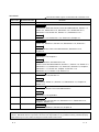
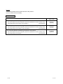
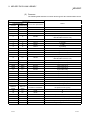
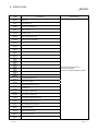
REVISIONS
The manual number is given on the bottom left of the back cover.
Print Date
Dec., 2000
Jun., 2001
Manual Number
Revision
IB(NA)-0800176-A First printing
IB(NA)-0800176-B Correction
CONTENTS, About the Generic Terms and Abbreviations, Section 1.2,
Section 3.4, Subsection 6.1.2, Subsection 7.2.3, Subsection 8.1.2,
Subsection 9.3.2, Section 9.4, Section 11.3, Subsection 11.3.1
Addition
Subsection 7.2.4, Subsection 7.2.5, Section 9.8, Chapter 10
Jan., 2002
IB(NA)-0800176-C
Correction
Section 3.4, Section 4.2, Section 4.3, Subsection 8.1.2, Section 9.7
Addition
About the Generic Terms and Abbreviations, Subsection 8.1.2,
Chapter 10
Dec., 2002
IB(NA)-0800176-D
Correction
Subsection 7.4.2, Chapter 9
Addition
Safety Precautions, Precautions for use,
Generic Terms and Abbreviations, Section 1.1, Section 1.2, Section 3.4,
Subsection 6.1.1, Subsection 6.1.2, Section 6.2, Section 6.3, Chapter 7,
Subsection 7.1.1, Section 9.3, Chapter 10, Section 11.3,
Subsection 11.3.1, Section 11.6, Section 11.7
Apr., 2004
IB(NA)-0800176-E
Correction
Precautions for use, Section 4.1
Addition
CONTENTS, Section 3.4, Section 4.4, Subsection 5.2.1, Chapter 10,
Section 11.7
Jun., 2004
IB(NA)-0800176-F
Correction
CONTENTS, Generic Terms and Abbreviations
Addition
Subsection 8.1.2, Appendix 1
Nov., 2005
IB(NA)-0800176-G
Correction
Precautions for use, Section 3.4, Subsection 6.1.1, Subsection 6.1.2,
Chapter 7, Section 11.2
Jun., 2006
IB(NA)-0800176-H
Correction
Section 3.3, Section 4.2, Section 5.4, Chapter 10
Japanese Manual Version IB-0800173-H
This manual confers no industrial property rights or any rights of any other kind, nor does it confer any patent
licenses. Mitsubishi Electric Corporation cannot be held responsible for any problems involving industrial property
rights which may occur as a result of using the contents noted in this manual.
© 2000 MITSUBISHI ELECTRIC CORPORATION
A-4
A-4
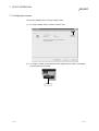
Precautions for use
(1) Operating environment of the personal computer used
Refer to Section 3.4 Operating Environment in this manual.
(2) Multi-thread communication
Multi-thread communication is not supported.
(3) Installation
Install the SW4DNF-CCLINK-B after uninstalling SWnDNF-CCLINK.
(4) Overwrite installation
When performing an overwrite installation, install in the same folder where the
previous program is installed.
(5) Start menu
When the software package is uninstalled, items may remain in the start menu.
In this case, reboot the computer.
(6) Software version of the CC-Link master and local modules
For the CC-Link master and local modules, use software version "N" or later.
A module running software version "M" or earlier will not run properly.
(7) CC-Link board ROM version
When connecting to the QCPU (Q mode), be sure to use a CC-Link board
whose ROM version is "W" or later.
The system will not operate correctly if a CC-Link board of "V" or older ROM
version is used.
(8) Multiprocessor PC
Multiprocessor PCs cannot be used because they are not supported by the
driver.
(9) Compatibility with Hyper-Threading technology
Hyper-Threading technology is unavailable as the driver does not support it.
When operating Windows XP Professional, disable the Hyper-Threading
technology on the BIOS setting screen of PC.
When operating Windows 2000 Professional, disable the Hyper-Threading
technology on the BIOS setting screen of PC and then reinstall the operating
system.
(For BIOS setting screen, read the manual of the PC used or confirm with the
PC manufacturer.)
R
R
(10) PC supporting PCI bus data parity error detection function
This board is incompatible with personal computers that detect the PCI bus
data parity errors.
For use of such a PC, set the PCI bus data parity error detection function to
OFF. Or, use a PC that does not have the function.
For whether the parity error detection function is provided or not and how to set
it off, please contact the PC manufacturer.
A-5
A-5
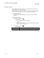
INTRODUCTION
Thank you for purchasing the Type A80BDE-J61BT13 CC-Link System Local Interface Board.
Before using the equipment, please read this manual carefully to develop full familiarity with the functions
and performance of the Type A80BDE-J61BT13 CC-Link System Local Interface Board you have purchased,
so as to ensure correct use.
Please forward a copy of this manual to the end user.
CONTENTS
SAFETY PRECAUTIONS..............................................................................................................................A- 1
REVISIONS ....................................................................................................................................................A- 4
Precautions for use ........................................................................................................................................A- 5
CONTENTS....................................................................................................................................................A- 6
Manuals ..........................................................................................................................................................A- 9
How to Read the Manual ...............................................................................................................................A-10
Generic Terms and Abbreviations .................................................................................................................A-11
Product List.....................................................................................................................................................A-12
1 OVERVIEW
1- 1 to 1- 3
1.1 Features .................................................................................................................................................. 1- 1
1.2 Combinations of Boards with Existing Software .................................................................................... 1- 2
2 EMC COMMAND
2- 1 to 2- 5
2.1 Requirements for EMC Command Compliance .................................................................................... 22.1.1 EMC commands............................................................................................................................... 22.1.2 Installation on the control panel ....................................................................................................... 22.1.3 Cable................................................................................................................................................. 22.1.4 Noise filter (power supply line filter)................................................................................................. 23 SYSTEM CONFIGURATION
3.1
3.2
3.3
3.4
3- 1 to 3- 6
System Configuration for A80BDE-J61BT13......................................................................................... 3Applicable System .................................................................................................................................. 3About Ver. 1.10 ....................................................................................................................................... 3Operating Environment........................................................................................................................... 3-
4 SPECIFICATION
1
2
3
4
4- 1 to 4- 7
4.1 General Specification.............................................................................................................................. 44.2 Performance Specifications .................................................................................................................... 44.2.1 Maximum overall cable distance (for Ver. 1.00).............................................................................. 44.2.2 Maximum overall cable distance (for Ver. 1.10).............................................................................. 44.3 CC-Link Dedicated Cable ....................................................................................................................... 44.4 List of Functions ...................................................................................................................................... 44.4.1 Multiple PLC system support ........................................................................................................... 4-
A-6
1
1
2
3
5
A-6
1
2
3
5
6
6
7
5 PROCEDURE AND SETTINGS UP TO THE POINT OF OPERATION
5- 1 to 5- 7
5.1 Procedure Up to the Point of Operation ................................................................................................. 55.2 Installation ............................................................................................................................................... 55.2.1 Precautions when handling.............................................................................................................. 55.2.2 Installation environment ................................................................................................................... 55.2.3 How to remove the terminal block ................................................................................................... 55.3 Name and Setting for Each Part............................................................................................................. 55.4 Connecting Modules Using the CC-Link Dedicated Cable.................................................................... 55.5 T-Branch Connection Using the CC-Link Dedicated Cable .................................................................. 56 INSTALLING AND UNINSTALLING THE SOFTWARE PACKAGE
1
2
2
3
3
4
5
7
6- 1 to 6-10
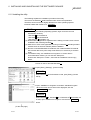
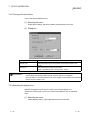
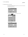
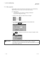
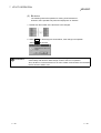
6.1 Installing the Software Package ............................................................................................................. 6- 1
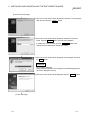
6.1.1 Installing the driver ........................................................................................................................... 6- 1
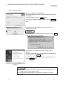
6.1.2 Installing the utility ............................................................................................................................ 6- 6
6.2 Icons to be Registered ............................................................................................................................ 6- 9
6.3 Uninstalling the Software Package......................................................................................................... 6-10
7 UTILITY OPERATION
7- 1 to 7-28
7.1 Utility Common Operations..................................................................................................................... 7- 1
7.1.1 Starting a utility ................................................................................................................................. 7- 1
7.1.2 Starting the device monitor utility..................................................................................................... 7- 1
7.1.3 Ending a utility .................................................................................................................................. 7- 2
7.1.4 Displaying the help screen............................................................................................................... 7- 3
7.1.5 Verifying the version......................................................................................................................... 7- 4
7.2 CC-Link Utility.......................................................................................................................................... 7- 5
7.2.1 Operation procedure ........................................................................................................................ 7- 5
7.2.2 Operations on Information screen ................................................................................................... 7- 6
7.2.3 Operations on Board Information screen ........................................................................................ 7- 7
7.2.4 Operations on Network Monitor screen........................................................................................... 7- 9
7.2.5 Operations on Station's Link Status screen .................................................................................... 7-10
7.2.6 Operations on Target screen ........................................................................................................... 7-11
7.2.7 Operations on Memory I/O Test screen .......................................................................................... 7-12
7.2.8 Operations on Network Test screen................................................................................................ 7-13
7.3 Device Monitor Utility .............................................................................................................................. 7-14
7.3.1 Operation procedure ........................................................................................................................ 7-14
7.3.2 Setting as batch monitoring ............................................................................................................. 7-15
7.3.3 Setting as 16 point register monitor................................................................................................. 7-16
7.3.4 Setting the monitoring destination ................................................................................................... 7-17
7.3.5 Setting the device to monitor ........................................................................................................... 7-18
7.3.6 Changing word device values.......................................................................................................... 7-19
7.3.7 Changing word device values continuously .................................................................................... 7-20
7.3.8 Tuning on/off a bit device................................................................................................................. 7-21
7.3.9 Switching the display form ............................................................................................................... 7-21
7.3.10 About the Numerical Input pad ....................................................................................................... 7-22
7.3.11 Other operations.............................................................................................................................. 7-23
A-7
A-7
7.4 Error Viewer ............................................................................................................................................ 7-25
7.4.1 Screen description............................................................................................................................ 7-25
7.4.2 Log menu.......................................................................................................................................... 7-26
7.4.3 View menu........................................................................................................................................ 7-27
8 ACCESSIBLE DEVICES AND RANGES
8- 1 to 8- 4
8.1 Accessible Devices ................................................................................................................................. 88.1.1 Host (personal computer (local station equivalent))........................................................................ 88.1.2 Other station ..................................................................................................................................... 88.2 Accessible Range ................................................................................................................................... 89 MELSEC DATA LINK LIBRARY
1
1
2
4
9- 1 to 9-10
9.1 Overview of the MELSEC Data Link Library.......................................................................................... 9- 1
9.2 Function List ............................................................................................................................................ 9- 2
9.3 Settings for Using Functions................................................................................................................... 9- 3
9.3.1 When using Visual Basic 5.0 and Visual Basic 6.0 ................................................................. 9- 3
9.3.2 When using Visual C++ 5.0 and Visual C++ 6.0 ...................................................................... 9- 3
9.4 Procedure for Programming ................................................................................................................... 9- 4
9.5 Channel ................................................................................................................................................... 9- 5
9.6 Station Number Settings......................................................................................................................... 9- 6
9.7 Device Types........................................................................................................................................... 9- 7
9.8 Sample Programs ................................................................................................................................... 9-10
R
R
R
R
10 ERROR CODE
10- 1 to 10- 10
11 TROUBLESHOOTING
11- 1 to 11-20
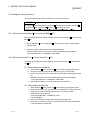
11.1 When Performing Troubleshooting..................................................................................................... 11- 1
11.2 Troubleshooting Table by the Type of Error Occurring ..................................................................... 11- 2
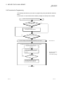
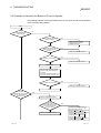
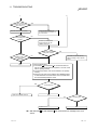
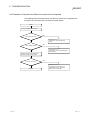
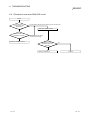
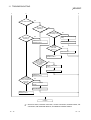
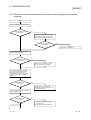
11.3 Flowchart to Use when the Board or PC do not Operate.................................................................. 11- 3
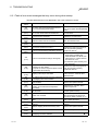
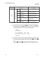
11.3.1 Table of error event messages that may occur during driver startup......................................... 11- 5
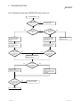
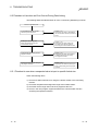
11.4 Flowchart to Use when the Data Link could not be Completed ........................................................ 11- 7
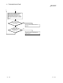
11.4.1 Flowchart to use when RUN LED is unlit .................................................................................... 11- 8
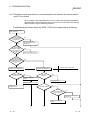
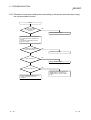
11.4.2 Flowchart to use when SD/RD LED does not turn on ................................................................ 11- 9
11.4.3 Flowchart to use when there is a communication error between the master station and
CC-Link board .............................................................................................................................. 11-10
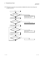
11.5 Flowchart to Use when an Error Occurs During Data Linking........................................................... 11-12
11.5.1 Flowchart to use when unexpected value is input to specific link device................................... 11-12
11.5.2 Flowchart to use when reading from and writing to the device cannot be done using the
communication function ............................................................................................................... 11-13
11.5.3 Flowchart to use when communication is disabled from time to time during user program
execution ...................................................................................................................................... 11-14
11.5.4 Flowchart to use when the system goes down or resets during the user program execution .. 11-15
11.6 Measures for WDT error occurrence.................................................................................................. 11-17
11.7 Precautions for installing other optional board................................................................................... 11-19
11.8 Information Needed when Calling with Inquiry................................................................................... 11-20
APPENDIX
App- 1 to App- 4
Appendix 1 Communication with the Redundant CPU ............................................................................App- 1
Appendix 2 External Dimensions..............................................................................................................App- 4
A-8
A-8
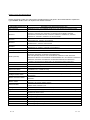
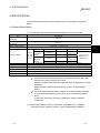
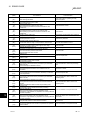
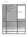
Manuals
The following table list the manuals relevant to this product.
You can order them as necessary.
Relevant Manuals
Manual Number
(Type Code)
Manual Name
CC-Link System Master/ Local type AJ61BT11/A1SJ61BT11 User’s Manual
This manual explains the system configuration, performance specifications, functions, handling, wiring
and troubleshooting for the AJ61BT11 and A1SJ61BT11.
(Sold separately)
CC-Link System Master/Local Module type AJ61QBT11/A1SJ61QBT11 User’s Manual
This manual explains the system configuration, performance specifications, functions, handling, wiring
and troubleshooting for the AJ61QBT11 and A1SJ61QBT11.
This manual explains the system configuration, performance specifications, functions, handling, wiring
A-9
IB-66722
(13J873)
(Sold separately)
CC-Link System Master/Local Module type QJ61BT11 User’s Manual
and troubleshooting for the QJ61BT11.
IB-66721
(13J872)
SH-080016
(13JL91)
(Sold separately)
A-9
How to Read the Manual
"How to Read the Manual" is listed according to the objective when using the CC-Link board.
Refer to the following when using this manual.
(1) To learn about the features of the CC-Link board (Section 1.1)
The features are described in Section 1.1.
(2) To learn about compatibility with existing software (Section 1.2)
Compatibility with existing software is described in Section 1.2.
(3) To learn about the correspondence to the EMC command
(Chapter 2)
Correspondence to the EMC command is described in Chapter 2.
(4) To learn about the system configuration (Section 3.1 to
Section 3.2)
Configuration of a system using the CC-Link board is described.
(5) To learn about the operating environment for the CC-Link board
(Section 3.3)
The operating environment for the CC-Link board is described in Section 3.3.
(6) To learn about specifications and functions for the CC-Link board
(Chapter 4)
The specifications and functions for the CC-Link board are described in
Chapter 4.
(7) To learn about CC-Link board settings (Chapter 5)
CC-Link board settings are described in Chapter 5.
(8) When installing or uninstalling a software package (Chapter 6)
How to install and uninstall a software packaged is described in Chapter 6.
(9) To learn about utilities operating procedure (Chapter 7)
The operating procedure for utilities is described in Chapter 7.
(10) To learn about devices that can be accessed and range of access
(Chapter 8)
Device specifications and contents stored in the system-area information are
described in Chapter 8.
(11) To learn about how to use functions (Chapter 9)
How to use functions is described in Chapter 9.
(12) To learn about error contents (Chapter 10)
The contents of errors is described in Chapter 10.
(13) To learn about the actions to take when the system does not run
(Chapter 11)
How to troubleshoot is described in Chapter 11.
A - 10
A - 10
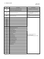
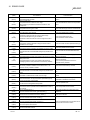
Generic Terms and Abbreviations
Unless specifically noted, this manual uses the abbreviations and generic terms listed below to explain the
Type A80BDE-J61BT13 CC-Link System local interface boards.
Abbreviation/generic term
CC-Link board
IBM PC/AT compatible PC
AnNCPU
AnACPU
AnUCPU
QnACPU
ACPU
QCPU (A mode)
QCPU (Q mode)
Redundant CPU
Master station
Local station
Remote I/O station
Remote station
Intelligent device station
Master and local modules
Master module
Remote module
Intelligent module
Cyclic transmission
Transient transmission
SB
SW
RX
RY
RWw
RWr
A - 11
Description of the abbreviation/generic term
Abbreviation for the Type A80BDE-J61BT13 CC-Link System local interface board.
An IBM PC/AT compatible PC.
Generic term for A0J2HCPU, A1SCPU, A1SCPU-S1, A1SCPUC24-R2, A1SHCPU,
A1SJCPU, A1SJCPU-S3, A1SJHCPU, A1SJHCPU-S8, A1NCPU, A2CCPU,
A2CCPUC24, A2CCPUC24-PRF, A2CJCPU, A2NCPU, A2NCPU-S1, A2SCPU,
A2SCPU-S1, A2SHCPU, A2SHCPU-S1 and A1FXCPU.
Generic term for A2ACPU, A2ACPU-S1, A2ACPUP21/R21, A2ACPUP21/R21-S1,
A3ACPUP21/R21, A3NCPU and A3ACPU.
Generic term for A2UCPU, A2UCPU-S1, A2ASCPU, A2ASCPU-S1, A2ASCPU-S30,
A2USHCPU-S1, A3UCPU and A4UCPU.
Generic term for Q2ACPU, Q2ACPU-S1, Q2ASCPU, Q2ASCPU-S1, Q2ASHCPU,
Q2ASHCPU-S1, Q3ACPU, Q4ACPU and Q4ARCPU.
Generic term for AnNCPU, AnACPU and AnUCPU.
Generic term for Q02CPU-A, Q02HCPU-A and Q06HCPU-A
Generic term for Q00JCPU, Q00CPU, Q01CPU, Q02CPU, Q02HCPU, Q06HCPU,
Q12HCPU, Q25HCPU, Q12PHCPU and Q25PHCPU.
Note that especially when the CPU is indicated as a different model, Q00JCPU,
Q00CPU and Q01CPU are described as Q00J/Q00/Q01CPU, and Q02CPU, Q02HCPU,
Q06HCPU, Q12HCPU and Q25HCPU as Q02/Q02H/Q06H/Q12H/ Q25HCPU.
In addition, Q12PHCPU and Q25PHCPU are described as the Process CPU.
Generic term for Q12PRHCPU and Q25PRHCPU.
The station controlling the remote station, local station and intelligent device station.
A station that has a CPU and can communicate with the master station and local station.
A remote station that can only handle bit information.
(AJ65BTB
-
, AJ65BTC
-
)
Generic term for the remote I/O station and remote device station.
A slave station such as the AJ65BT-R2 in the CC-Link system that can perform transient
transmission.
Generic term for the AJ61QBT11, A1SJ61QBT11, AJ61BT11, A1SJ61BT11 and
QJ61BT11.
Generic term when the AJ61QBT11, A1SJ61QBT11, AJ61BT11, A1SJ61BT11 and
QJ61BT11 are used as master stations.
Generic term for AJ65BTB
-
, AJ65BTC
-
, AJ65BT-64AD, AJ65BT-64DAV,
AJ65BT-64DAI, A852GOT, etc.
A module such as the AJ65BT-R2 that can perform transient transmission.
Function that periodically updates the contents of the remote I/O and remote register.
Function that communicates data to the specified station when there is an access
request from the PLC CPU.
Link special relay
Link special register
Remote input
Remote output
Remote register (write area)
Remote register (read area)
A - 11
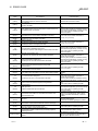
Product List
The product list for the CC-Link board is given in the table below.
Product name
A80BDE-J61BT13 CC-Link System local interface board
SW4DNF-CCLINK-B model CC-Link software package
Quantity
1
1
(Floppy disks; set of 6)
Type A80BDE-J61BT13 CC-Link System local interface board user's manual (this manual)
1
Software use agreement
1
Note
The terminal resistor is packaged with the CC-Link system master and local
modules.
A - 12
A - 12
1 OVERVIEW
MELSEC
1 OVERVIEW
This manual explains the specifications for, and how to handle and monitor the Type
A80BDE-J61BT13 CC-Link System local interface board (hereinafter abbreviated as
CC-Link board) that is included in the CC-Link system, and loaded as an optional
board in the PCI bus of an IBM PC/AT compatible PC.
The A80BDE-J61BT13 is applicable to the following CC-Link system.
• Applicable to the CC-Link system local station(s).
1.1 Features
The I/F board has the features described below.
(1) An IBM PC/AT compatible PC can be built into the CC-Link system.
The I/F board can be installed in an IBM PC/AT compatible PC and that PC can
be used as a local station.
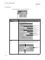
(2) Using a PCI bus eliminates troublesome switch settings.
Simply installing the board in the PCI bus automatically executes initial setting.
(3) Displays test and monitor information related to the CC-Link.
Operation becomes easy since the CC-Link system testing and monitoring
statuses can be displayed in the IBM PC/AT compatible PC.
(4) Various functions are available to accommodate user
programming.
By using various functions that are compatible with Microsoft Visual C++ and
Microsoft Visual Basic , user applications to perform remote control for the PLC
CPU as well as reading from and writing to devices can easily be created.
R
R
R
R
(5) Drivers for various operating systems are available.
A variety of drivers are provided to make it easier to construct a system that is
compatible with the user’s environment.
Compatible operating systems :
Microsoft Windows 95 Operating System (English Version)
Microsoft Windows 98 Operating System (English Version)
Microsoft Windows NT Workstation Operating System Version 4.0 (English
Version)
Microsoft Windows 2000 Professional Operating System (English Version)
Microsoft Windows XP Professional Operating System (English Version)
R
R
R
R
R
R
R
R
R
R
(6) Support for QCPUs (Q mode) of a multiple PLC system
By specifying the station number of the logical station number via the CC-Link
utility, communication with each QCPU (Q mode) of a multiple PLC system can
be performed.
1-1
1-1
1
1 OVERVIEW
MELSEC
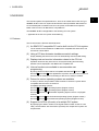
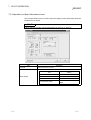
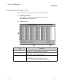
1.2 Combinations of Boards with Existing Software
1
This section describes the combinations of boards with existing software.
(1) When using the CC-Link board and other interface boards in the
same PC
Board model name
Q80BD-J71LP21-25
Q80BD-J71LP21G
Q80BD-J71LP21GE
Q80BD-J71BR11
Supported OS
Software package
name
DOS
NT 3.51 Win 95
Win 98
Win Me
NT 4.0
Win
2000
XP
Pro
XP
Home
2
SW0DNC-MNETH-B
SW0IVDWT-MNET10P
A70BDE-J71QLP23
SW1IVDWT-MNET10P
A70BDE-J71QLP23GE
SW2DNF-MNET10
A70BDE-J71QBR13
SW3DNF-MNET10
A70BDE-J71QLR23
1
1
SW3DNF-MNET10
SW3DNF-CCLINK
A80BDE-J61BT11
A80BDE-A2USH-S1
3
SW4DNF-CCLINK-B
SW0DNF-ANU-B
SW1DNF-ANU-B
DOS : MS-DOS 6.2
NT 3.51 : Windows NT Workstation 3.51
Win 95 : Windows 95
Win 98 : Windows 98
Win Me: Windows Me NT 4.0 : Windows NT Workstation 4.0
Win 2000 : Windows 2000 Professional
XP Pro : Windows XP Professional
XP Home : Windows XP Home Edition
: Can be operated simultaneously.
: Cannot be operated simultaneously.
— : No combination available
R
R
R
R
R
R
R
R
indicates an OS that is not supported by the CC-Link board. It cannot be used on the same PC.
1 : The user program EXE file that was generated using MDFUNC32.LIB must be re-linked using the
MDFUNC32.LIB that comes with SW4DNF-CCLINK-B.
2 : Supports Windows XP Professional from Version 70H or later.
3 : Supports Windows XP Professional from Version 40E or later.
R
R
1-2
1-2
1 OVERVIEW
MELSEC
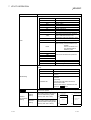
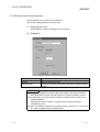
(2) When using the CC-Link board, Communication Support Software
Tool and GX Developer in the same PC
Software name
Supported OS
Software package
name
DOS
NT 3.51
Win 95
1
SW1D5F-CSKP-E
Win 98
Win Me
NT 4.0
1
Win
2000
XP
Pro
XP
Home
1
SW2D5F-CSKP-E
SW2D5F-OLEX-E
SW2D5F-XMOP-E
SW3D5F-CSKP-E
Communication Support
SW3D5F-OLEX-E
Software Tool
SW3D5F-XMOP-E
SW0D5C-ACT-E
SW2D5C-ACT-E
SW3D5C-ACT-E
SW1D5C-SHEET-E
SW2D5F-GPPW-E/
SW2D5C-GPPW-E
2
SW3D5F-GPPW-E/
SW3D5C-GPPW-E
SW4D5C-GPPW-E
GX Developer
SW5D5C-GPPW-E
SW6D5C-GPPW-E
SW7D5C-GPPW-E
SW8D5C-GPPW-E
DOS : MS-DOS 6.2
NT 3.51 : Windows NT Workstation 3.51
Win 95 : Windows 95
Win 98 : Windows 98
Win Me: Windows Me NT 4.0 : Windows NT Workstation 4.0
Win 2000 : Windows 2000 Professional
XP Pro : Windows XP Professional
XP Home : Windows XP Home Edition
: Can be operated simultaneously.
: Cannot be operated simultaneously.
— : No combination available
: Cannot access the CC-Link board, and cannot access other stations via the CC-Link board.
R
R
R
R
R
R
R
R
indicates an OS that is not supported by the CC-Link board. It cannot be used on the same PC.
1 : Update the version of each software if it is used with the CC-Link board on the same PC.
For details on version update products, contact your local Mitsubishi service center or representative.
2 : Supports Windows 98 from Version 30D or later.
R
1-3
1-3
2 EMC COMMAND
MELSEC
2 EMC COMMAND
2.1 Requirements for EMC Command Compliance
EMC commands, which are among the European command sets, are now enforced.
The EMC commands regulate "emission (electromagnetic interference)," which
requires that a device not emit strong electromagnetic waves externally, and "immunity
(electromagnetic sensitivity)," which requires that a device have the ability to resist
external electromagnetic waves.
The precautionary items when configuring a machine device using an CC-Link board
to conform to EMC commands are described in sections 2.1.1 through 2.1.4.
Although we tried very hard to document these materials according to the
requirements for regulation and the standards we have researched, the compatibility to
the above commands of the entire device created according to the contents of this
material, is not guaranteed. The methods to enable a device to conform to the
commands and the compatibility must be determined by the manufacturer who
produces the machine device.
2
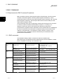
2.1.1 EMC commands
The standards relating to EMC commands are listed in the table below:
With all test items, the standard has been tested with each device installed in an IBM
PC/AT compatible PC bearing a CE certification logo.
Specification
EN50081-2 :
1995
prEN50052-2 :
1991
EN50082-2 :
1995
Test item
EN55011
Radiated noise
Test description
Measure the electric wave
released by the product.
Standard values
30 M-230 MHz QP : 50 dBµV/m
1
(3 m measurement)
230 M-1000 MHz QP : 57 dBµV/m
(3 m measurement)
EN55011
Conduction noise
Measure the noise released by
the product to the power line.
IEC801-2
Static electricity immunity
IEC801-3
Radiated electromagnetic field
IEC801-4
First transient burst noise
Immunity test by applying static
electricity to the unit enclosure.
Immunity test by radiating an
electric field to the product.
Immunity test by applying burst
noise to the power line and
signal line.
Immunity test by applying static
electricity to the unit enclosure.
Immunity test by applying burst
noise to the power line and
signal line.
Immunity test by radiating an
electric field to the product.
150 k-500 kHz
QP: 79 dB, Mean: 66 dB
500 k-30 MHz
QP: 73 dB, Mean: 60 dB
4 kV contact discharge
8 kV air discharge
10 V/m, 27 - 500 MHz
EN61000-4-2
Static electricity immunity
EN61000-4-4
First transient burst noise
ENV50140
Radiated electromagnetic field
AM modulation
ENV50204
Radiated electromagnetic field
Pulse modulation
ENV50141
Conduction noise
2 kV
4 kV contact discharge
8 kV air discharge
2 kV
10 V/m, 80-1000 MHz, 80 % AM
modulation@1 kHz
Immunity test by radiating an
electric field to the product.
10 V/m, 900 MHz, 200 Hz pulse
modulation, 50 % duty
Immunity test by inducting
electromagnetic field to the
power line and signal line.
10 Vrms, 0.15-80 MHz, 80 % AM
modulation@1 kHz
1 QP (Quasi-Peak) : Quasi-peak value, Mean: Average value
2-1
2-1
1
2 EMC COMMAND
MELSEC
2.1.2 Installation on the control panel
Installing devices on the control panel has a considerable effect not only in securing
safety but also in shutting down the noise generated from the PC by the control panel.
(1) Control panel
(a) Use an electrically conductive control panel.
(b) When fastening tightening the control panel's top or bottom panel with bolts,
mask the coating so that surface contact is feasible.
(c) To ensure the electrical contact between the inside panel of the control panel
and the main control panel, mask any coating around the installation bolts
connecting to the main unit to secure conductivity in the largest surface area
possible.
(d) Ground the control panel main unit using a thick ground cable so that a low
impedance can be secured even with a high frequency.
(e) Make the holes on the control panel less than 10 cm (3.94 in.) in diameter. A
hole larger than 10 cm (3.94 in.) may leak electric waves.
(2) Layout of power supply cable and ground cable
The layout of power supply cable and ground cable for a PC should be set as
described below.
(a) Specify a grounding point that enables grounding of the control panel close to
the power supply to the PC and ground the FG (frame ground) terminal of
the PC or the SLD (shield) terminal of the CC-Link board using the thickest,
shortest cable possible (about 30 cm (11.81 in.) or less in length). Since the
FG and SLD terminals play a role in grounding the noise generated in the
PC, it is necessary to ensure the lowest possible impedance. Because the
power line is used to allow the noise to escape, it actually contains a great
deal of noise. Therefore, shortening the wire length prevents the power line
from becoming an antenna.
Note : A long conductive material can become an antenna that emits noise more
efficiently.
(b) Twist the ground cable leading to the ground point with the power supply
cable. By twisting them with the ground cable, the noise leaking out of the
power supply cable may be grounded at a higher rate. However, when a
noise filter is installed to the power supply cable, twisting with the ground
cable may not be necessary.
2-2
2-2
2
2 EMC COMMAND
MELSEC
2.1.3 Cable
Because the cable that runs from the control panel contains high frequency noise,
outside the control panel it acts as an antenna and radiates noise. Always use shielded
cable for cable that runs outside the control panel.
Except for certain models, using the ferrite core is not mandatory. However, the noise
radiated via cable can be suppressed more effectively by mounting a ferrite core.
Using a shielded cable is also effective in raising noise resistance. The signal lines
used for PLC input/output and special units are designed to ensure a noise resistance
level of 2 kV (IEC801-4/EN61000-4-4) if a shielded cable is used. If a shielded cable is
not used, or when a shielded cable is not grounded properly, the noise resistance will
drop below 2 kV.
Note : With the EN50082-2, the noise resistance of each signal line is specified based
on the application of the signal.
Signals related to control (process control)
: 2 kV
Signals not related to control (process control)) : 1 kV
In the EN50082-2, the meaning of “(signals) related to control” is not defined. However,
considering the original intent of the EMC command, the signal line that poses possible
danger to person or equipment when the panel is incorrectly operated shall be defined
as the “signal related to control,” and high noise resistance is considered mandatory.
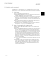
(1) Grounding treatment for shields
(a) Perform shielding processing at a position near the exit of the control panel.
If the grounding point is far from the exit position, the cable portion after the
grounding point will cause electromagnetic induction and generates highfrequency noise.
(b) Use a grounding method that allows the shield a surface grounding in a large
area against the control panel. A clamping fixture as shown below may
alternatively be used. When such a fixture is used, mask the coating in the
area inside the control panel where the fixture contacts.
Shielded section
Screw
Clamping fixture
Coating mask
Shielded cable
Note : The method shown below in which a PVC electric wire is soldered to the
shield of the shielded cable and that end is grounded, increases the high
frequency impedance and the effectiveness of the shield is lost.
Shielded cable
PVC electric wire
Crimp contact
2-3
2-3
2 EMC COMMAND
MELSEC
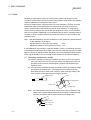
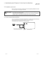
(2) Grounding treatment for the CC-Link dedicated cable
(a) Always ground the twisted cable connected to the CC-Link master station,
local station and remote station.
Since the twisted cable is a shielded cable, remove part of the outer sheath.
Then ground the exposed part of the shield indicated in the figure below as
wide a surface area as possible.
Control panel
All of this area should be grounded.
Always use the cable specified for
this cable.
CC-Link dedicated cable
Shield
Remote station
Local station
Remote station
Control panel
Also, ground within 30 cm (11.81.in.) from the board terminal area in addition
to grounding at the position closest to the exit of the control panel.
(b) Always use the specified cable for the CC-Link dedicated cable.
(c) For each module, do not use a ferrite core for the CC-Link dedicated cable
from the board.
(d) For each module, ground both the FG terminal and SLD terminal of the
board.
CC-Link dedicated cable
Terminal
resistor
Master module
Remote module
Local module
DA
DA
DA
DB
DB
DB
DG
DG
DG
SLD
SLD
SLD
FG
2-4
24V
24V
24G
24G
FG
FG
Terminal
resistor
2-4
2 EMC COMMAND
MELSEC
2.1.4 Noise filter (power supply line filter)
A noise filter is a part that has a considerable effect in preventing conductive noise.
Except for a few models, installation of a noise filter to the power supply line is not
mandatory. However, the installation of a noise filter can suppress noise at a higher
rate (a noise filter is effective for reducing noise emitted in the range below 10MHz).
Use a noise filter equivalent to the models shown below.
Model
FN343-3/01
FN660-6/06
ZHC2203-11
Manufacturer
SCHAFFNER
SCHAFFNER
TDK
Rated current
3A
6A
3A
Rated voltage
250 V
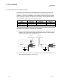
Precautions when installing a noise filter are noted below.
(1) Do not bundle the wiring on the input and output side of the noise filter. If they are
bundled, noise on the output side will be inducted to the wiring on the input side
where the noise has been removed by a filter.
Input side
(power supply side)
Filter
Induction
Output side
(device side)
Input side
(power supply side)
Filter
Induction
Output side
(device side)
(2) Ground the ground terminal for the noise filter to the control panel using as short
wiring as possible (about 10 cm (3.94 in.)).
2-5
2-5
3 SYSTEM CONFIGURATION
MELSEC
3 SYSTEM CONFIGURATION
The configuration for a system using the CC-Link board is explained below.
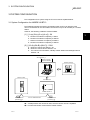
3.1 System Configuration for A80BDE-J61BT13
The following indicates the system configuration when an CC-Link board is used.
The CC-Link board can be connected to a maximum of up to 26 modules per 1 master
station.
However, the following conditions must be fulfilled.
(1) {(1×a)+(2×b)+(3×c)+(4×d)} ≤ 64
a:
b:
c:
d:
3
Number of modules occupied by 1 station
Number of modules occupied by 2 stations
Number of modules occupied by 3 stations
Number of modules occupied by 4 stations
(2) {(16×A)+(54×B)+(88×C)} ≤ 2304
A : Number of remote I/O stations ≤ 64
B : Number of remote device stations ≤ 42
C : The number of local stations, standby master stations and intelligent device
stations ≤ 26
An IBM PC/AT Compatible PC equipped
with a PCI bus 1
Operating system
has been installed.
Software package
SW4DNF-CCLINK-B
Master module
CC-Link board
A80BDE-J61BT13
Terminal resistor
(mandatory) 2
CC-Link dedicated cable
Terminal resistor
(mandatory) 2
1 : A multiprocessor PC cannot be used, since the drivers are not compatible.
2 : The terminal resistor comes with the master module.
3-1
3-1
3 SYSTEM CONFIGURATION
MELSEC
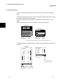
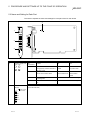
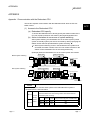
3.2 Applicable System
The CC-Link system master module which can use an CC-Link board is explained
below.
The master module that can use an CC-Link board is the product with function version
B or later and software version N or later.
The product with earlier versions than those listed above cannot use an CC-Link
board.
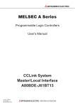
The function version is recorded in the DATE column of the rated plate.
3
<Large type>
<Small type>
CPU UNIT
PROGRAMMABLE CONTROLLER
MODEL
DATE
DATE
9712
B
9712
B
MITSUBISHI ELECTRIC CORPORATION JAPAN
BD992D008H40
Year and month
of manufacture
Function
version
BD992D008H40
MITSUBISHI ELECTRIC
Year and month
of manufacture
Function
version
The function version is noted only on products with version B or later.
The software version is indicated on the module version tag located on the front of the
module.
A1SJ61BT11
AJ61BT11
RUN
ERR.
MST
S MST
LOCAL
CPU R/W
E
R
R
O
R
SW
M/S
PRM
TIME
LINE
156K
625K
2.5M
5M
10M
B
R
A
T
E
RUN
ERR.
MST
S MST
LOCAL
CPU R/W
L RUN
L ERR.
STATION NO.
TEST
S0
S1
S2
SW
M/S
PRM
TIME
LINE
E
R
R
O
R
SD
RD
MODE
T
E
S
T
Software version
L RUN
L ERR.
SD
RD
Hardware version
Software version
Hardware version
3-2
3-2
3 SYSTEM CONFIGURATION
MELSEC
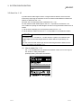
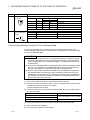
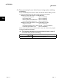
3.3 About Ver. 1.10
A product with a cable length of 20cm or longer between stations, which has been
achieved by improving the restriction on the conventional cable distance between the
stations, is defined as Ver. 1.10.
Whereas, the conventional product is defined as Ver. 1.00.
For the maximum total cable length for the Ver. 1.10 products, see Section 4.2.2.
The conditions requiring the cable length to be 20cm or longer between stations are as
follows:
1) All the units comprising a CC-Link system must be of Ver. 1.10.
2) All the data link cables must be Ver. 1.10-compatible CC-Link dedicated cables.
POINT
If modules of Ver. 1.00 and Ver. 1.10 are mixed in a system, the maximum total
cable length and the cable length between stations will be as specified by Ver.
1.00.
For the maximum total cable length and the cable length between stations for the
Ver. 1.00 products, see Section 4.2.1.
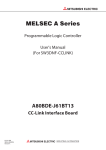
(1) How to check Ver. 1.10
Ver. 1.10-compatible CC-Link boards and modules contain a "CC-Link" logo on
the "board" or "rating name plate."
(Example) Rating name plate of AJ61BT11
PROGRAMMABLE CONTROLLER
DATE
MADE IN JAPAN
3-3
BD992C077H01
3-3
3 SYSTEM CONFIGURATION
MELSEC
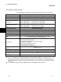
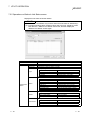
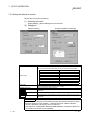
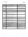
3.4 Operating Environment
The following table shows the operating environment for the CC-Link board.
Item
Personal
computer
Description
CPU
Required
memory
PCI bus
specifications
4,
Operating system
5
IBM-PC/AT-compatible personal computer with one or more PCI bus slots, satisfying the
specifications described below in "Applicable operating system and the corresponding
required PC performance" 1, 2, 3.
5V DC, 32-bit bus, Basic clock: 33MHz
Microsoft
Microsoft
Microsoft
Microsoft
Microsoft
R
R
R
R
R
Windows 95 Operating System (English version)
Windows 98 Operating System (English version)
Windows NT Workstation Operating System Version 4.0 (English version)
Windows 2000 Professional Operating System (English version) 6
Windows XP Professional Operating System (English version) 6
R
R
R
7
R
Display
Resolution: 800 600 dot or higher (Recommended: 1024 768 dot)
Available hard disk space
15MB or more
Disk drive (required when
installing the driver)
Programming
language 9, 10, 11
6,
R
8
3.5 inch (1.44MB) floppy disk drive
Microsoft Visual Basic 5.0 (English version), Microsoft Visual Basic 6.0 (English version),
Microsoft Visual C++ 5.0 (English version), Microsoft Visual C++ 6.0 (English version)
R
R
R
R
R
R
R
R
1: This product does not work with a multiprocessor IBM-PC/AT-compatible personal computer, as the driver is
incompatible.
2: Hyper-Threading technology is unavailable as the driver does not support it.
When operating Windows XP Professional, disable the Hyper-Threading technology on the BIOS setting screen of
PC.
When operating Windows 2000 Professional, disable the Hyper-Threading technology on the BIOS setting screen of
PC and then reinstall the operating system.
(For BIOS setting screen, read the manual of the PC used or confirm with the PC manufacturer.)
3: PC supporting PCI bus data parity error detection function
This board is incompatible with personal computers that detect the PCI bus data parity errors. For use of such a PC,
set the PCI bus data parity error detection function to OFF. Or, use a PC that does not have the function.
For whether the parity error detection function is provided or not and how to set it off, please contact the PC
manufacturer.
4: This board does not support the Standby (Hibernate) mode of the operating system.
The Standby (Hibernate) mode may be preset to some personal computers so that it will be activated by pressing the
Power switch or by the UPS (Uninterruptible Power Supply system) setting.
For Windows 2000 Professional, select [Settings] – [Control Panel] – [Power Options] and disable the standby mode
setting.
5: When exiting the operating system, always shut down the computer.
6: Installation, uninstallation and usage of utilities are available only by the administrator’s authority.
7: Service Pack3 or higher is required when using Windows NT Workstation 4.0.
8: This product does not comply with large-sized fonts when Windows 2000 Professional or Windows XP Professional
is used.
9: User programs created in the English environment work only in the English environment.
10: Use Visual Basic 6.0 or Visual C++ 6.0 when using Windows 2000 Professional or Windows XP Professional.
(Visual Basic 5.0 and Visual C++ 5.0 cannot be used.)
11: This product is not compatible with Microsoft Visual Basic NET or Microsoft Visual C++ .NET.
R
R
R
R
R
R
R
R
R
R
R
R
3-4
R
R
R
R
3-4
3 SYSTEM CONFIGURATION
MELSEC
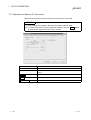
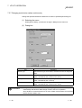
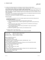
Applicable operating system and the corresponding required PC performance
Description
Operating system
CPU
Pentium
Pentium
Pentium
Pentium
Pentium
Windows 95
R
Windows 98
R
Windows NT Workstation 4.0
R
Windows 2000 Professional
R
Windows XP Professional
R
R
R
R
R
R
Required memory
133MHz or higher
133MHz or higher
133MHz or higher
133MHz or higher
300MHz or higher
32MB or more
32MB or more
32MB or more
64MB or more
128MB or more
POINT
New functions of Windows XP
When Microsoft Windows XP Professional Operating System is used, the
following new functions cannot be used.
If any of the following new functions is used, this product may not operate normally.
Start of application in Windows compatible mode
Fast user switching
Remote desktop
R
R
R
R
3-5
3-5
3 SYSTEM CONFIGURATION
MELSEC
MEMO
3-6
3-6
4 SPECIFICATION
MELSEC
4 SPECIFICATION
The performance specifications and functions of the CC-Link board are explained
below.
4.1 General Specification
(1) The following table indicates general specifications of the CC-Link board.
Item
Specification
Usage ambient
temperature
0 to 55 °C
Storage ambient
temperature
-20 to 75 °C
Usage ambient humidity
10 to 90 %RH, no condensation
Storage ambient humidity
10 to 90 %RH, no condensation
Frequency
Amplitude
Sweep count
0.075 mm
When there is
10 to 57 Hz
—
Conformin
(0.0030 inch)
intermittent
g to JIS B
10 times in each
vibration
57 to 150 Hz
9.8 m/s2
—
3501, IEC
direction X, Y, Z
0.035 mm
When there is
61131-2
(80 minutes)
10 to 57 Hz
—
(0.0013 inch)
continuous
2
4.9 m/s
vibration
57 to 150 Hz
—
Conforming to JIS B 3501, IEC61131-2 (147 m/s2, 3 times each in 3 directions)
Vibration durability
Shock durability
Usage environment
No corrosive gas
Usage height
Less than 2000 m (less than 6562 ft.)
Installation area
Within the control board
Over-voltage category
Pollution level
Acceleration
2
1
Less than II
Less than 2
1 Indicates the location where the device is connected from the public cable
network to the device structure wiring area.
Category II applies to the devices to which the power is supplied from a fixed
equipment.
Surge withstand voltage for devices with up to 300 V of rated voltage is
2500 V.
2 This is an index which indicates the degree of conductive object generation
in the environment Pollution level 2 is when only non-conductive pollution
occurs.
A temporary conductivity caused by condensation must be expected
occasionally.
(2) General specifications of the CC-Link board or the IBM PC/AT compatible
personal computer, whichever is lower, must be satisfied after installation.
4-1
4-1
4
4 SPECIFICATION
MELSEC
4.2 Performance Specifications
The following table indicates the performance specifications for the CC-Link board.
Item
Specification
Transmission speed
156 kbps, 625kbps, 2.5 Mbps, 5 Mbps or 10 Mbps can be selected
Maximum transmission distance
Differs depending on the transmission speed. (Refer to Section 4.2.1, 4.2.3)
Number of occupied stations
1 or 4 station(s) (switches depending on the setting)
Maximum number of link points
per 1 system
Remote I/O (RX, RY)
: 2048
Remote registers (RWw) : 256 (master station to local station)
Remote registers (RWr) : 256 (local station to master station)
Number of link points per 1
station
Remote I/O (RX, RY)
: 30
Remote registers (RWw) : 4 (master station to local station)
Remote registers (RWr) : 4 (local station to master station)
Communication method
4
Broadcast polling method
Synchronous method
Frame synchronous method
Encoding method
NRZI method
Transmission path
Bus (RS-485)
Transmission format
Conforms to HDLC
Error control system
CRC(X16+X12+X +1)
5
CC-Link dedicated cable/ CC-Link dedicated high performance cable/
Ver. 1.10-compatible CC-Link dedicated cable 1
Cable
RAS functions
Number of boards that can be
loaded
Loading slot
•
•
•
•
•
•
•
Automatic return function
Slave station separation function
Error detection using the link special relay and register
Data link status verification
OFF-line test (hardware test, line test)
Abnormal temperature detection
Watchdog timer error (WDT) detection
Maximum of 4
IBM PC/AT compatible PC
Number of slots occupied
1 slot
Internal voltage consumption
(5 V DC)
0.4 A
Weight
2
PCI bus slot
0.16 kg
1: Ver.1.10-compatible CC-Link dedicated cables, CC-Link dedicated cables (Ver.1.00) and CC-Link
dedicated high-performance cables cannot be used together. If used together, correct data transmission
will not be guaranteed. Also attach the terminating resister which matches the kind of the cable. (Refer to
section 5.4)
2: This indicates the total number of A80BDE-J61BT11 and A80BDE-J61BT13 boards.
4-2
4-2
4 SPECIFICATION
MELSEC
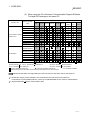
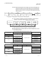
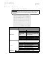
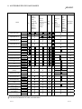
4.2.1 Maximum overall cable distance (for Ver. 1.00)
The relationship between the transmission speed and the maximum overall cable
distance is described below:
(1) For a system consisting of only remote I/O stations and remote
device stations
Remote I/O station
or remote
device station
Remote I/O station
or remote
device station
Master station
2
2
Remote I/O station
or remote
device station
1
Remote I/O station
or remote
device station
1
Maximum overall cable distance
1 Cable length between remote I/O stations or remote device stations.
2 Cable length between the master station and the adjacent stations.
CC-Link dedicated cable (uses terminal resistor 110 Ω)
Transmission rate
156 kbps
625 kbps
2.5 Mbps
Station-to-station cable length
1
2
1200 m (3937.2 ft.)
600 m (1968.6 ft.)
200 m (656.2 ft.)
30 cm (11.81 in.) or more
30 cm (11.81 in.) to
59 cm (23.23 in.)
60 cm (23.62 in.) or more
30 cm (11.81 in.) to
59 cm (23.23 in.)
60 cm (23.62 in.) to
99 cm (38.98 in.)
1 m (3.28 ft.) or more
5 Mbps
10 Mbps
Maximum overall cable distance
110 m (360.9 ft.)
1 m (3.28 ft.) or more
150 m (492.15 ft.)
50 m (164.1 ft.)
80 m (262.5 ft.)
100 m (328.1 ft.)
CC-Link dedicated high performance cable (uses terminal resistor 130 Ω)
Transmission rate
156 kbps
625 kbps
2.5 Mbps
5 Mbps
Number of connected
stations: 1 to 32
Number of connected
stations: 33 to 48
10 Mbps
Number of connected
stations: 49 to 64
Station-to-station cable length
1
2
Maximum overall cable distance
1200 m (3937.2 ft.)
900 m (2952.9 ft.)
400 m (1312.4 ft.)
160 m (524.96 ft.)
30 cm (11.81 in.) or more
100 m (328.1 ft.)
30 cm (11.81 in.) to
39 cm (15.35 in.)
40 cm (15.75 in.) or more
30 cm (11.81 in.) to
39 cm (15.35 in.)
40 cm (15.75 in.) to
69 cm (27.17 in.)
70 cm (27.56 in.) or more
1 m (3.28 ft.) or more
80 m (262.5 ft.)
100 m (328.1 ft.)
20 m (65.52 ft.)
30 m (98.43 ft.)
100 m (328.1 ft.)
The cable length between remote I/O stations or remote device stations is within this range and if even one location is wired, the
maximum overall cable distance will be as indicated above.
4-3
4-3
4 SPECIFICATION
MELSEC
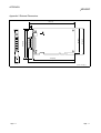
(Example) When the transmission rate is 10 Mbps, and 43 remote I/O stations and
remote device stations are connected using the CC-Link dedicated high
performance cable, because the cable connecting the second and third
stations is "35 cm (13.78 in.)", the maximum overall cable distance will be
"80 cm (31.5 in.)".
Master station
First
Second
Third
4th
43th
Remote I/O station
Remote device
station
Remote I/O station
Remote I/O station
Remote device
station
1 m (3.28 ft.)
50 cm (19.69 in.)
35 cm (13.78 in.)
50 cm (19.69 in.)
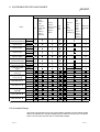
(2) For a system consisting of remote I/O stations, remote device
stations, local stations and intelligent device stations
2
1
Local station
or Intelligent
device station
Local station
or Intelligent
device station
Remote I/O station
or remote
device station
Remote I/O station
or remote
device station
Master station
2
2
Maximum overall cable distance
1 Cable length between remote I/O stations or remote device stations
2 Cable length between the master station or the local or intelligent device station
and the adjacent stations
CC-Link dedicated cable (uses terminal resistor 110 Ω)
Transmission rate
156 kbps
625 kbps
2.5 Mbps
Station-to-station cable length
1
2
1200 m (3937.2 ft.)
600 m (1968.6 ft.)
200 m (656.2 ft.)
30 cm (11.81 in.) or more
30 cm (11.81 in.) to
59 cm (23.23 in.)
60 cm (23.62 in.) or more
30 cm (11.81 in.) to
59 cm (23.23 in.)
60 cm (23.62 in.) to
99 cm (38.98 in.)
1 m (3.28 ft.) or more
5 Mbps
10 Mbps
Maximum overall cable distance
110 m (360.9 ft.)
2 m (6.56 ft.) or more
150 m (492.15 ft.)
50 m (164.1 ft.)
80 m (262.5 ft.)
100 m (328.1 ft.)
CC-Link dedicated high performance cable (uses terminal resistor 130 Ω)
Transmission rate
156 kbps
625 kbps
2.5 Mbps
5 Mbps
10 Mbps
Station-to-station cable length
1
2
1200 m (3937.2 ft.)
600 m (1968.6 ft.)
200 m (656.2 ft.)
30 cm (11.81 in.) or more
30 cm (11.81 in.) to
59 cm (23.23 in.)
60 cm (23.62 in.) or more
70 cm (27.56 in.) to
99 cm (38.98 in.)
1 m (3.28 ft.) or more
Maximum overall cable distance
2 m (6.56 ft.) or more
110 m (360.9 ft.)
150 m (492.15 ft.)
50 m (164.1 ft.)
80 m (262.5 ft.)
The cable length between remote I/O stations or remote device stations is within this range and if even one location is wired, the
maximum overall cable distance will be as indicated above.
4-4
4-4
4 SPECIFICATION
MELSEC
4.2.2 Maximum overall cable distance (for Ver. 1.10)
The relation of the transmission speed and maximum overall cable distance when
configuring the entire system with Version 1.10 modules and cable is shown below.
Master station
Remote I/O station
or remote
device station
Remote I/O station
or remote
device station
Local station or
intelligent device
station
Local station or
intelligent device
station
Station to station
cable length
Maximum overall cable distance
Version 1.10 compatible CC-Link dedicated cable (terminal resistor of 110Ω used)
Transmission speed
Maximum overall cable distance
156kbps
1200m (3937.2 ft.)
625kbps
900m (2952.9 ft.)
2.5Mbps
4-5
Station to station cable length
20cm (7.88 in.) or longer
400m (1312.4 ft.)
5Mbps
160m (524.96 ft.)
10Mbps
100m (328.1 ft.)
4-5
4 SPECIFICATION
MELSEC
4.3 CC-Link Dedicated Cable
Use the CC-Link dedicated cable for the CC-Link system. If a cable other than the CCLink dedicated cable is used, the performance of the CC-Link system cannot be
guaranteed.
If you have any questions regarding the CC-Link dedicated cable, or if you wish to see
its specifications, see the CC-Link Partner Association homepage http://www.cclink.org/.
4.4 List of Functions
The following table lists the CC-Link board functions.
Name
Data communication
function
Contents
(1) Communication for remote input (RX), remote output (RY), remote
register (RWw, RWr) via the CC-Link is possible using the cyclic
transmission function.
• Number of link points per station
Remote I/O (RX, RY)
: 30
Remote register (RWw) : 4
Remote register (RWr)
:4
(2) Communication with the master station and intelligent device station is
possible using the transient transmission function.
Test function
Tests can be performed and the hardware checked using the test mode
setting.
RAS functions
Automatic return function, slave station separation function, verification of
Self-diagnostic function
• An error message is displayed according to the error code.
data link status, off-line test
• Contents of the fault detected are stored in the special relay or special
register.
POINT
Refer to the QJ61BT11N User’s Manual for whether the cyclic data can be
transmitted to/from stations compatible with CC-Link Ver.2.
(Please read the reference section replacing "QJ61BT11N" with "CC-Link board".)
4-6
4-6
4 SPECIFICATION
MELSEC
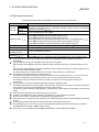
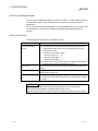
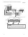
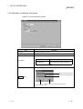
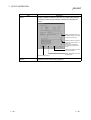
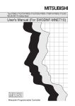
4.4.1 Multiple PLC system support
By setting the logical station number using the CC-Link utility, any PLC of a multiple
PLC system in which a QJ61BT11 is installed can be accessed by an IBM PC/AT
compatible PC in which a CC-Link board is installed.
<Access example>
Using logical station number “65,” an access can be made from an IBM PC/AT
compatible PC in which a CC-Link board is installed to the PLC No. 4 via a
QJ61BT11 (the control PLC is the PLC No.2).
Multiple PLC system
Local station
(CC-Link board)
PLC
No.1
• • • •
PLC
No.2
PLC
No.3
PLC
No.4
Master station
Station number: 0
(PLC No. 2 is the control PLC.)
QJ61
BT11
• • • •
Terminal
register
[Setting the logical station number]
Set the logical station number in the "Target" window of the CC-Link utility.
For details on the "Target" window, see Section 7.2.6.
POINT
Use a QJ61BT11 of functional version B or later in order to access a multiple PLC
system.
A QJ61BT11 of functional version A cannot be used.
4-7
4-7
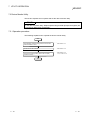
5 PROCEDURE AND SETTINGS UP TO THE POINT OF OPERATION
MELSEC
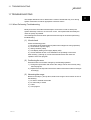
5 PROCEDURE AND SETTINGS UP TO THE POINT OF OPERATION
This section explains the operating procedure up to the point the CC-Link board is
operated, as well as the names and setting for each part of the CC-Link board, wiring
method and hardware testing.
5.1 Procedure Up to the Point of Operation
An outline of the procedure up to the point of CC-Link board operation is explained
below.
Start
Perform CC-Link board settings.
· · · · · · See Section 5.3, "Name and Setting for Each Part."
If the power to the PC is on, turn the power off.
Remove the CC-Link board terminal block.
Install the CC-Link board into the PC.
5
Fix the CC-Link board with the PC's board fixing screws.
Install the CC-Link board terminal block.
Do the wiring between the CC-Link board and the master module.
· · · · · · See Section 5.4,
"Connecting Modules Using the CC-Link Dedicated Cable"
Turn on the power to the PC and install the software package.
· · · · · · See Chapter 6,
"INSTALLING AND UNINSTALLING SOFTWARE PACKAGE."
Test the CC-Link board.
· · · · · · See Section 7.2.8,
"Operation of the Memory I/O Test screen"
Perform data link settings for the CC-Link board.
· · · · · · See Section 7.2,
"CC-Link Utility"
Startup the CC-Link system.
Execute PC programs.
Complete
Note
Setting on the master module side is mandatory in order to run the CC-Link system.
Perform the settings for the master module side as required.
See the user manual for the master module regarding the master module settings.
5-1
5-1
5 PROCEDURE AND SETTINGS UP TO THE POINT OF OPERATION
MELSEC
5.2 Installation
This section gives precautions when handling the CC-Link board and explains the
installation environment.
5.2.1 Precautions when handling
The followings are precautions to be noted when handling the CC-Link board.
DANGER
• Do not touch the terminal or the connector while the power is turned on.
Doing so may result in electric shock or cause malfunctioning.
CAUTION
• Fasten the CC-Link board securely using the installation screws and tighten the
installation screws securely within the specified torque range.
If the screws are loose, this may cause malfunctioning.
If the screws are tightened too much, this could cause damage to the screws or
module, leading to malfunctioning.
• Do not directly touch the conductive section of the CC-Link board.
Doing so could result in malfunctioning or breakdown of the CC-Link board.
• Before handling the CC-Link board, touch a grounded metal object to discharge the
static electricity from the human body.
Failure to do so may cause failure or malfunction of the CC-Link board.
• Tighten the terminal screws within the specified torque range.
If the terminal screws are loose, this may lead to a short or malfunctioning.
If the terminal screws are tightened too much, this could cause damage to the
screws or CC-Link board, leading to a short or malfunctioning.
• Handle the CC-Link board in a location where there is no static electricity.
Static electricity could result in failure or malfunctioning.
• Take care that foreign objects such as chips or wiring debris do not get into the PC.
This could result in fire, breakdowns or malfunctioning.
• Do not dismantle or rebuild the CC-Link board.
This will result in failure, malfunctioning, injury or fire.
• Always turn off all external power before installing or removing the CC-Link board.
If power is not turned off at all phases, there is a risk of electric shock or damage to
the product.
• When discarding the product, handle it as an industrial waste.
• Do not drop the CC-Link board or subject it to strong impact.
This will result in failure or malfunctioning of the board.
(1) The tightening torque for the CC-Link board terminal screws and fixing screws
should fall within the range indicated in the table below.
Screw locations
Tightening torque range
Terminal block terminal screws (M3.5 screw)
59 to 88 N⋅cm
Terminal block installation screws (M3.5 screw)
59 to 88 N⋅cm
(2) See the manual attached to the PC unit for the tightening torque of CC-Link board
installing screws.
5-2
5-2
5
5 PROCEDURE AND SETTINGS UP TO THE POINT OF OPERATION
MELSEC
5.2.2 Installation environment
See the instruction manual accompanying the PC unit regarding installation of the PC
unit in which the CC-Link board is mounted.
CAUTION
• Always ground the PC unit using grounding type D (Class 3 grounding). Otherwise,
there is the risk of malfunctioning.
If there is an error in operation even when the PC unit is grounded, ground the FG
terminal of the PC unit as well as the SLD terminal of the CC-Link board.
5.2.3 How to remove the terminal block
The CC-Link board uses a two-piece terminal block, so that the CC-Link board can be
replaced without disconnecting the signal line to the terminal block.
The illustration below shows how to remove the block.
Screwdriver
HIGH
LOW
Remove the two screws at both ends
of the terminal block and pull them out.
5-3
5-3
5 PROCEDURE AND SETTINGS UP TO THE POINT OF OPERATION
MELSEC
5.3 Name and Setting for Each Part
This section explains the name and settings for each part of the CC-Link board.
4)
RUN ERR
HIGH
1)
LOW
SD
RD
2)
1 2
3)
BD
NO.
Number
1)
Name
Operation display LED
RUN ERR
SD
2)
RD
Terminal block for the
data link
Contents
LED
nomenclature
Contents
ON
OFF
RUN
Lights when the CC-Link board is
running properly and turns off when a
WDT error occurs
CC-Link board is
normal
WDT error
PC power is OFF
ERR.
Lights when there is an error in the
network communication status
Data link
communication error
Data link
communication
normal
SD
Flashes when the data link is
transmitting data
Flashes while the data link is transmitting
RD
Flashes when the data link is receiving
data
Flashes while the data link is receiving
Connect a CC-Link dedicated cable to perform the data link.
(2-piece terminal block)
Upper surface
of the board
DA
DB
DG
SLD
5-4
5-4
5 PROCEDURE AND SETTINGS UP TO THE POINT OF OPERATION
Number
3)
Name
MELSEC
Contents
Channel number
setting switch
Sets the channel number for the CC-Link board.
1 2
ON
BD
NO.
Board number Channel
number
Switch
1
2
Notes
0
81
OFF
OFF
1
82
ON
OFF
2
83
OFF
ON
3
84
ON
ON
Default setting
Set the board number, so that there is no duplication when two or more CC-Link boards are installed.
4)
Switch setting pin for
abnormal temperature
detection
Sets the temperature at which to be detected when there is an abnormal temperature.
Setting
Contents
HIGH
Set the detect temperature at 55 °C.
LOW
Set the detect temperature at 45 °C.
Notes
Default setting
HIGH
LOW
5.4 Connecting Modules Using the CC-Link Dedicated Cable
This section describes how to connect the CC-Link board, master module, local
module, standby master module, remote module, and intelligent device module using
the CC-Link dedicated cable.
IMPORTANT
(1) Be sure to turn off the power to the corresponding station before attaching and
removing a terminal block. If the terminal block is attached or removed without
turning off the power to the corresponding station, normal data transfer will not
be guaranteed.
(2) The CC-Link dedicated cables, the high-performance CC-Link dedicated cables
and Ver.1.10-compatible CC-Link dedicated cables cannot be used together. If
they are used together, normal data transfer will not be guaranteed.
(3) Be sure to ground the main body of an IBM PC/AT compatible PC using ClassD grounding (Class 3 grounding) or higher. Otherwise, malfunction may occur.
If malfunction occurs when only the main body of an IBM PC/AT compatible PC
is grounded, ground the FG terminal of the IBM PC/AT compatible PC and the
SLD terminal of the CC-Link board.
(1) The order of cable connection is irrelevant to the station number.
(2) Be sure to connect a "terminal resistor," which is provided with the module, tothe
modules at both ends of the CC-Link system.
Connect it between DA and DB.
(3) Terminal resistors to be connected are different depending on the cable used by
the CC-Link system:
Cable type
CC-Link dedicated cable
Version 1.10-compatible CC-Link dedicated cable
CC-Link dedicated high-performance cable
Terminal resister
110 Ω 1/2 W (brown - brown - brown)
130 Ω 1/2 W (brown - orange - brown)
(4) The master module can be connected to locations other than both ends.
(5) Star connection is not allowed.
(6) The connection method is shown below.
5-5
5-5
5 PROCEDURE AND SETTINGS UP TO THE POINT OF OPERATION
MELSEC
Master module
Terminal
resistor
Module other
QJ61BT11
than QJ61BT11
NC
DA
NC
DB
NC
DG
NC
NC
NC
DA
SLD
DB
Remote module
A80BDE-J61BT13
FG
DG
SLD
DA
DB
DG
DA
SLD
DG
+24V
24G
NC
FG
Terminal
resistor
CC-Link dedicated cable
DB
SLD
FG
Ground the SLD terminal of
A80BD-J61BT13 as needed
[Simplified Diagram] The following shows a simplified diagram of the connection
diagram on the previous page.
Master module
Terminal
resistor
A80BDE-J61BT13
Remote module
DA
DA
DA
DB
DB
DB
DG
DG
DG
SLD
SLD
SLD
FG
CC-Link
dedicated cable
CC-Link
dedicated cable
Ground the SLD terminal
of A80BDE-J61BT13
as needed
Terminal
resistor
FG
POINT
(1) The layouts of the terminal block for the QJ61BT11 and of the terminal blocks
for other than the QJ61BT11 are different. Exercise caution when wiring them.
(2) Be sure to connect a “terminal resistor,” which is provided with the master
module, to the modules at both ends of the data link. (Connect it between DA
and DB.)
5-6
5-6
5 PROCEDURE AND SETTINGS UP TO THE POINT OF OPERATION
MELSEC
5.5 T-Branch Connection Using the CC-Link Dedicated Cable
For details on the T-branch connection using the CC-Link Dedicated cable, refer to the
following manuals:
• CC-Link System Master/Local Module Type QJ61BT11 User’s Manual
• CC-Link System Master/Local Module Type AJ61BT11/A1SJ61BT11 User’s Manual
• CC-Link System Master/Local Module Type AJ61QBT11/A1SJ61QBT11 User’s
Manual
• A80BDE-J61BT11 CC-Link System Master/Local Interface Board User’s Manual (For
SW4DNF-CCLINK-B)
5-7
5-7
6 INSTALLING AND UNINSTALLING THE SOFTWARE PACKAGE
MELSEC
6 INSTALLING AND UNINSTALLING THE SOFTWARE PACKAGE
This section explains how to install and uninstall the software package.
6.1 Installing the Software Package
The following explains the installation procedure of the driver and the installation
procedure of the utility.
6.1.1 Installing the driver
The following explains the installation procedure of the CC-Link board driver.
POINT
(1) When Microsoft Windows NT Workstation Operating System Version 4.0 is
used, the installation of the CC-Link board driver is not required.
(2) When using the following Operating systems, logon as a user who has
administrator authority.
• Windows XP Professional
• Windows 2000 Professional
(3) Disassociate all applications registered in the startup procedure, then execute
installation after restarting Windows .
(4) Make sure to close other applications running on Windows (including resident
software such as antivirus software) before installation.
R
R
R
R
R
R
(1) When Microsoft Windows 2000 Professional Operating System is
used
R
R
1. Mount the CC-Link board to a PC, then power on the PC to start
Windows 2000 Professional.
R
2. When the screen shown left is displayed, click the Next> button.
3. When the screen shown left is displayed, select "Search for a suitable
driver for my device [recommended]," then click the Next> button.
(To the next page)
6-1
6-1
6
6 INSTALLING AND UNINSTALLING THE SOFTWARE PACKAGE
MELSEC
(From the previous page)
4. When the screen shown left is displayed, select "Specify a location"
and click the Next> button.
5. When the screen shown left is displayed, enter "A:\Win2000\Us" for
"Copy manufacturer's files from." Insert Disk 6 into the floppy disk
drive, then click the OK button.
6. When the screen shown left is displayed, click the Next> button.
6
7. The installation is complete when the screen shown left is displayed.
Click the Finish button.
(Complete)
6-2
6-2
6 INSTALLING AND UNINSTALLING THE SOFTWARE PACKAGE
MELSEC
(2) When Microsoft Windows XP Professional Operating System is
used.
R
R
1. Mount a CC-Link board to a PC, and then power on the PC to start
Windows XP Professional.
R
2. When the screen shown left is displayed, select "Install from a list or
specific location (Advanced)" and then click the NEXT button.
3. As the screen shown left is displayed, select "Search for the best
driver in these locations".
Check "Include this location in the search" and enter
"A:\Win2000\Us".
Insert Disk 6 into the floppy disk drive, and then click the Next>
button to start the drive installation.
4. When the screen shown left is displayed, this means that the
installation is completed.
Click the Finish button.
(Complete)
6-3
6-3
6 INSTALLING AND UNINSTALLING THE SOFTWARE PACKAGE
MELSEC
(3) When Microsoft Windows 95 Operating System or Microsoft
Windows 98 Operating System is used
R
R
R
R
1. Mount the CC-Link board to a PC, then power on the PC to start
Windows 95 or Windows 98.
R
R
2. When the screen shown left is displayed, click the Next> button.
3. When the screen shown left is displayed, select "Search for the best
driver for your device [Recommended]," then click the Next>
button.
4. When the screen shown left is displayed, check "Specify a location,"
enter "A:\Win9x\Us" for the search location, then insert Disk 6 into
the floppy disk drive.
(To the next page)
6-4
6-4
6 INSTALLING AND UNINSTALLING THE SOFTWARE PACKAGE
MELSEC
(From the previous page)
5. The driver file for the device will be searched.
Click the Next> button.
6. The installation is complete when the screen shown left is displayed.
Click the Finish button.
(Complete)
6-5
6-5
6 INSTALLING AND UNINSTALLING THE SOFTWARE PACKAGE
MELSEC
6.1.2 Installing the utility
The following explains the installation procedure of the utility.
The screens of Windows 2000 Professional are used in the explanation.
Therefore, these screens are slightly different from other operating systems.
R
Install the utilities with reference to REMARK .
POINT
(1) When using the following Operating systems, logon as a user who has
administrator authority.
• Windows XP Professional
• Windows 2000 Professional
• Windows NT Workstation 4.0
(2) Disassociate all applications registered in the startup procedure, then execute
installation after restarting Windows .
(3) Make sure to close other applications running on Windows (including resident
software such as antivirus software) before installation.
(4) Be sure to uninstall SWnDNF-CCLINK first, then install SW4DNF-CCLINK-B.
Since all the data set by each utility will be erased, it is necessary to set them
again.
(5) To install the utility, use "Add/Remove Programs" in "Control Panel."
As an alternative method, you can execute "Setup.exe".
Double-click "Setup.exe" in Disk 1, then start the installation from item [6.]
below.
R
R
R
R
R
1. Power on the PC and start Windows .
R
2. Open [Start] - [Settings] - [Control Panel].
REMARK
When Windows XP Professional is used, open [Start] - [Control
Panel].
R
3. Open "Add/Remove Programs" and select "Add New Program."
When the screen shown at the left is displayed, click the
CD or Floppy button.
REMARK
When Windows 95, Windows 98, or Windows NT Workstation 4.0
R
R
R
is used, open "Add/Remove Programs" and click the Install...
button.
(To the next page)
6-6
6-6
6 INSTALLING AND UNINSTALLING THE SOFTWARE PACKAGE
MELSEC
(From the previous page)
4. When the screen shown left is displayed, insert Disk 1 into the floppy
disk drive and click the Next> button.
5. When the screen shown left is displayed, "Setup.exe" has been
found. Click the Finish button and start the installation.
If "Setup.exe" was not found, click the Browse... button and
change to the location where "Setup.exe" exists.
6. When the screen shown left is displayed, select "English" and click
the OK button.
REMARK
Do not select Japanese.
When selecting Japanese, the message in the following dialog box
will not be displayed correctly.
7. When the screen shown left is displayed, click the Next> button.
(To the next page)
6-7
6-7
6 INSTALLING AND UNINSTALLING THE SOFTWARE PACKAGE
MELSEC
(From the previous page)
8. Specify the installation destination folder.
The default installation destination folder of SW4DNF-CCLINK-B is
"C:\MELSEC."
To accept the default, click the Next> button.
To change the installation destination folder, click the Browse...
button.
9. The installation will start. Switch floppy disks in the order, as
instructed on the screen.
REMARK
If the following screen is displayed during installation, click the Yes
button and continue with the installation.
10.The installation is complete when the screen shown left is
displayed.
To restart, confirm that "Yes, I want to restart my computer now" is
checked, then click the Finish button.
To restart later, check "No, I will restart my computer later," then
click the Finish button.
(Complete)
POINT
(1) If the installation failed to complete and it is possible to uninstall the software
package, execute the uninstall procedure.
(2) To reinstall the software package, uninstall it first, restart the PC, and then
reinstall.
6-8
6-8
6 INSTALLING AND UNINSTALLING THE SOFTWARE PACKAGE
MELSEC
6.2 Icons to be Registered
When the software package is installed, the following icons are registered in [Start] [Programs] - [MELSEC].
REMARK
When Windows XP Professional is used, the following icons are registered in [Start] [All Programs] - [MELSEC].
R
Icon
Utility name
CC-Link utility
Error Viewer
1: Supported for Windows
6-9
R
Description
Starts the CC-Link utility.
1
95 and Windows
Starts Error Viewer.
R
98 only.
6-9
6 INSTALLING AND UNINSTALLING THE SOFTWARE PACKAGE
MELSEC
6.3 Uninstalling the Software Package
The following explains how to uninstall the software package.
The screens of Windows 2000 Professional are used in the explanation.
Therefore, these screens are slightly different from other Operating systems.
R
Uninstall the utilities with reference to REMARK .
POINT
(1) When using the following Operating systems, logon as a user who has
administrator authority.
• Windows XP Professional
• Windows 2000 Professional
• Windows NT Workstation 4.0
(2) Disassociate all applications registered in the startup procedure, then execute
uninstallation after restarting Windows .
(3) Make sure to close other applications running on Windows (including resident
software such as antivirus software) before uninstallation.
(4) Always uninstall from Control Panel.
Do not directly start the installed "UnInstaller.exe."
(5) To reinstall the software package, uninstall it first, restart the PC, and then
reinstall.
R
R
R
R
R
1. Open [Start] - [Settings] - [Control Panel].
REMARK
When Windows XP Professional is used, open [Start] - [Control
Panel].
R
2. Open "Add/Remove Programs" and select "Change or remove
programs."
Select SW4DNF-CCLINK-B and click the Change/Remove
button.
REMARK
When Windows 95, Windows 98, or Windows NT Workstation 4.0
R
R
R
is used, select SW4DNF-CCLINK-B and click the Add/Remove...
button.
When Windows XP Professional is used, select SW4DNF-CCLINKR
B and then click on the Change/Remove button.
3. When the screen shown left is displayed, click the Yes button to
begin uninstalling the software package.
4. After the uninstall procedure of the software package is complete,
click the OK
(Complete)
6 - 10
6 - 10
7 UTILITY OPERATION
MELSEC
7 UTILITY OPERATION
POINT
When using the following Operating systems, logon as a user who has
administrator authority.
• Windows XP Professional
• Windows 2000 Professional
• Windows NT Workstation 4.0
R
R
R
7.1 Utility Common Operations
This section explains the common operations for each utility.
7.1.1 Starting a utility
An utility can be started by clicking on the following menus found in the [Start] –
[Program 1] – [MELSEC] menu.
Starts the CC-Link Utility.
Starts the Error Viewer.
2
1: When Microsoft Windows XP Professional Operating System is used, [All programs] is
displayed.
2: The error viewer is registered only when the operating system is Microsoft Windows 95
Operating System or Microsoft Windows 98 Operating System.
R
R
R
R
R
R
7.1.2 Starting the device monitor utility
The following explains how to start the device monitor utility from the CC-Link utility.
The device monitor utility can be started by clicking on the Device Monitor button
found at the bottom of the CC-Link utility screen.
Click !
7-1
7-1
7
7 UTILITY OPERATION
MELSEC
7.1.3 Ending a utility
This section explains how to end a utility.
(1) To end the utility, click the Exit button at the bottom of the utility screen.
Click !
(2) To end the device monitor utility, click [Menu] – [Exit] from the menu bar.
When a dialog box is displayed, clicking the Yes button ends the device
monitor utility.
7
Click !
(3) To end the error viewer, click [Log] – [Exit] menu from the menu bar.
Click !
7-2
7-2
7 UTILITY OPERATION
MELSEC
7.1.4 Displaying the help screen
This section explains how to display the utility's help screen.
(1) To display the utility's help screen, click the Help button at the lower right-hand
corner of the utility screen.
Click !
(2) To display the help screen for the device monitor utility and error viewer, click
[Help] – [Help] from the menu bar.
Click !
7-3
7-3
7 UTILITY OPERATION
MELSEC
7.1.5 Verifying the version
This section explains how to verify the utility version.
(1) To verify a utility's version, click the "Version" tab.
Click !
(2) To verify the version for the device monitor utility and error viewer, click [Help] [Version] from the menu bar.
Click !
7-4
7-4
7 UTILITY OPERATION
MELSEC
7.2 CC-Link Utility
This section explains how to operate the CC-Link utilities.
7.2.1 Operation procedure
The following explains the operation procedure for the CC-Link utilities.
Start
· · · · · · See section 5.1.
Connect a PC to CC-Link.
Perform settings using the CC-Link utilities.
Perform settings using the board
information screen.
· · · · · · See Section 7.2.3.
Confirm the host line status using the
network monitor screen.
· · · · · · See Section 7.2.4.
To check the list of boards, use the
information screen.
· · · · · · See Section 7.2.2.
To confirm the line status of other
stations, use the station's link status screen.
· · · · · · See Section 7.2.5.
To access a multiple PLC system,
set the logical station number in the
target screen.
· · · · · · See Section 7.2.6.
To perform a diagnosis of the memory and
I/O and board reset use, the memory I/O
test screen.
· · · · · · See Section 7.2.7.
To perform a network test, use the network
test screen.
· · · · · · See Section 7.2.8.
End
7-5
7-5
7 UTILITY OPERATION
MELSEC
7.2.2 Operations on Information screen
The hardware information that is set for CC-Link board is displayed.
Item
Channel No.
7-6
Description
Displays the channel number.
Board Model Name
Displays the model of CC-Link board that is connected.
IRQ No.
Displays the IRQ number that CC-Link board uses.
Memory Address
Displays the range of dual-port memory that CC-Link board occupies.
I/O Port no.
Displays the ranges of I/O port that CC-Link board occupies.
ROM Ver.
Displays the ROM version of CC-Link board.
7-6
7 UTILITY OPERATION
MELSEC
7.2.3 Operations on Board Information screen
The card information screen is used to set and to display various information about the
installed CC-Link board.
POINT
When switching screens, set the mode setting to "On-line" or "Off-line."
Item
Channel
Description
Sets a channel to be used.
Sets information on the host.
Item
Board Setting
Station number
Station 1 to 64
Number of stations occupied
1 station/4 stations
Data entered at fault
Latch/clear
Transmission Speed
7-7
Setting
156 k/625 k/2.5 M/5 M/10
Mbps
7-7
7 UTILITY OPERATION
MELSEC
Item
Description
Display present status of CC-Link board.
LED name
LED On
RUN
ERR.
MST
LOCAL
CPU R/W
SW
M/S
PRM
CC-Link system normal
Communication abnormal
Master station
Local station
Communicating
Switch setting error
Master station duplication error
Parameter error
No response is received from all stations
due to cable disconnection or the
transmission path being affected by noise.
Cable disconnection error
Data link running
When lit: Communication error
When blinking: A terminal resistor is not
installed.
The CC-Link board or CCLink dedicated cable is
affected by noise.
TIME
LINE
L RUN
LED
L ERR.
156k
625k
2.5M
5M
10M
TEST
SD
RD
LED for the set transmission speed is lit.
Off-line test executing
Data transmitting
Data receiving
Perform the mode setting for the CC-Link board, and display the present mode
status.
Mode
Online
Offline
Mode Setting
Hardware test
Data
Used for normal communication
Becomes the state when not connected to the
network.
Executes a test of the A80BDE-J61BT13
hardware.
[Procedure]
Connect a terminal resistor between the
terminal DA and DB.
Set the mode setting to "Hardware test" and
press the
Apply
7-8
button.
The contents of the setting with respect to the CC-Link board selected by the
channel are updated.
button
Random
Access Buffer
Setting
Apply
Default
Setting
The random access buffer area is
used via default setting. (Buffer
memory area: A00H to FFFH)
Extension
Setting
The random access buffer area is
used via extension setting. (Buffer
memory area: A00H to 2FFFH)
Range of random access buffer area
<At extension setting>
<At default setting>
A00H
to
FFFH
1000H
Random access
buffer area
A00H
to
to
2FFFH
System area
Random access
buffer area
2FFFH
7-8
7 UTILITY OPERATION
MELSEC
7.2.4 Operations on Network Monitor screen
This screen monitors the line status of the host.
POINT
To restart monitoring after monitoring stops due to an error, display a screen other
than the "Network Monitor" screen first, and then display the "Network Monitor"
screen again.
Item
Description
Displays the channel number.
Displays the station number of the host.
Monitors and displays the startup status of the data link.
Channel
St.
Status
Initial status
No parameter
Data linking
Data link stopping
Disconnecting (Not
poling)
Disconnecting (Line Error)
Disconnecting (others)
Line testing
Data Link Status
Parameter Set testing
Automatic returning
Resetting
Contents
Data link is in initial status.
Parameters have not been received.
The data link is being executed.
The data link has stopped.
There is no inquiry from the master station and
the link is disconnected.
The link is disconnected due to an error in the line.
The link is disconnected due to other reasons.
A line test is being performed.
A test is being performed on the parameter
settings from the master station.
A return is automatically being processed.
The board is being reset.
Monitors and displays the error status.
Display
Normal
Transmission Error
Parameter Error
CRC Error
Time Out Error
Error Status
Abort Error
Setting Error
Other Error
Link Scan Time
7-9
Max
Current
Min
Contents
Normal status
Error in communication path was detected.
Error in parameters was detected.
CRC error was detected.
Timeout error was detected.
An error in the CC-Link board (gate array) was
detected.
Error in the setting was detected.
Error arising from some other cause was detected.
Displays the maximum value for the link scan time. (1 ms unit)
Displays the current value for the link scan time.
(1 ms unit)
Displays the minimum value for the link scan time. (1 ms unit)
7-9
7 UTILITY OPERATION
MELSEC
7.2.5 Operations on Station's Link Status screen
Displays the line status of another station.
POINT
(1) The Station's Link Status only monitors when the host status is "data linking."
(2) To restart monitoring after monitoring stops due to an error, display a screen
other than the " Station's Link Status" screen first, and then display the
"Station's Link Status" screen again.
Item
Channel
Board Setting
St.
Occupy St.
Type
Description
Sets the channel to be used.
Displays information on the host.
Displays the station number that has been set.
Displays the number of stations occupied.
Displays the type of the station that is set.
Display
Remote Device
Remote I/O
Intelligent
Contents
Remote device station
Remote I/O station
Intelligent station, local station
Displays the status of another station.
Other Station
Status
Status
Display
Communicating
Communication interrupted
Link error
WDT error
Fuse brake off
Repeated station
Moved switch
Contents
Normal
Communication is stopped
There is a link error
A watchdog timer error occurred
A station has blown a fuse
There are duplicate station numbers
Switch was changed
Displays the station with an error invalid.
Invalid
Display
Error invalid station
(Free)
Contents
There is a setting
No setting
Displays the status of a transient error.
Transient Err
7 - 10
Display
Transient Error
(Free)
Contents
There is an error
No error
7 - 10
7 UTILITY OPERATION
MELSEC
Item
Description
A list of communication status for other stations is displayed.
When a reserve station has been set in the data link parameter that is to set in
the master station, the reserve station is displayed as a normal communication
station in the following list of other station communication statuses.
All Station View button
7.2.6 Operations on Target screen
Set the logical station number to access a multiple PLC system.
Item
Description
Channel
Select the channel for setting the destination.
Logical Set No.
Enter the logical station number to be set or modified (setting range: 65 to 239).
Sta. No.
Enter the station number of a QJ61BT11 that is controlled by a multiple PLC system.
Target CPU
Enter the target PLC to be accessed.
Set button
Register the contents of the setting to the destination list.
Change button
Select the line to be changed, then click this button to modify the registered data. (The same
operation will result by double-clicking the line to be changed.)
Delete button
7 - 11
Select the line to be deleted, then click this button to delete the registered station number.
7 - 11
7 UTILITY OPERATION
MELSEC
7.2.7 Operations on Memory I/O Test screen
Diagnoses the dual-port memory and I/O port used by the CC-Link board.
POINT
(1) Start the diagnostic operation after disconnecting the external cable.
(2) To switch the screens during the diagnostic operation, click the Stop button
to terminate the diagnosis and then switch screens.
Item
Description
Channel
Set the channel to be used.
Diagnose
Displays the address being diagnosed and number of the diagnosis and
status.
7 - 12
Start button
Starts the memory and I/O diagnosis.
Stop button
Terminates the memory and I/O diagnosis.
Board Reset button
Resets the CC-Link board.
7 - 12
7 UTILITY OPERATION
MELSEC
7.2.8 Operations on Network Test screen
Tests the CC-Link board that is loaded.
Item
Channel
Board Setting
Description
Sets the channel to be used.
Displays information on the host.
Sets the items to be tested.
Test Mode
Item
Network Test
Setting
Performs a test for data link start and
stop.
The following dialog box is displayed by clicking.
Select when starting data link.
Select when stopping data link.
Start button
Closes the dialog box sithout performing the test.
Clicking this starts the test.
7 - 13
7 - 13
7 UTILITY OPERATION
MELSEC
7.3 Device Monitor Utility
This section explains how to operate and set the device monitor utility.
POINT
In the device monitor utility, SB (link special relay) and SW (link special register) are
indicated as SM and SD, respectively.
7.3.1 Operation procedure
The following explains how to operate the device monitor utility.
Start
Select [Setting] - [Network setting] from the menu bar and
set the channel to be used.
· · · · · · See Section 7.3.4
Set the device to be monitored.
· · · · · · See Section 7.3.5.
Change the monitoring method, device value or display
format as necessary.
· · · · · · See Section 7.3.2,
7.3.3, 7.3.6 to 7.3.11
End
7 - 14
7 - 14
7 UTILITY OPERATION
MELSEC
7.3.2 Setting as batch monitoring
Monitors only one device that has been specified.
(1) Selecting the menu
Select [Menu] – [Batch monitor] from the menu bar.
(Selectable for 16-point register monitor only.)
(2) Display screen
1)
2)
Item
1) Device information
3)
Description
Displays the current device status.
See Section 7.3.9 when the display form is changed.
2) Network status
Displays the network status currently set.
See Section 7.3.4 when the network is set.
3) Data Format
Shows a display form and device types being displayed (word device
and bit device).
See Section 7.3.5 when the device type is changed.
And, see Section 7.3.9 when the display form is changed.
7 - 15
7 - 15
7 UTILITY OPERATION
MELSEC
7.3.3 Setting as 16 point register monitor
Monitors up to five bit devices and one word device simultaneously.
(1) Selecting the menu
Select [Menu] – [16 point register monitor] from the menu bar.
(Selectable at batch monitoring only.)
(2) Display screen
1)
2)
Item
1) Device information
3)
Description
Displays the current device status.
See Section 7.3.9 when changing the display form.
2) Network status
Displays the network status currently set.
See Section 7.3.4 when setting the network.
3) Data Format
Shows a display form and device types being displayed (word device
and bit device).
See Section 7.3.5 when changing the device type.
And, see Section 7.3.9 when changing the display form.
7 - 16
7 - 16
7 UTILITY OPERATION
MELSEC
7.3.4 Setting the monitoring destination
Sets the network to be used for device monitoring.
Set this when starting the device monitor utility.
(1) Selecting the menu
Select [Setting] – [Network Setting] from the menu bar.
(2) Dialog box
Item
Channel
Description
Sets the channel to be used.
Network Setting
Sets the host and other stations along with network number and station
number.
POINT
(1) To access a multiple PLC system, select other station, then enter the value of
the "logical station number" set with the CC-Link utility for the station number.
(2) Do not specify a CC-Link remote I/O station or intelligent device station as the
monitor destination.
Specifying a remote I/O station or intelligent device station generates a
corresponding error.
(3) When own station is selected in the network setting, network No. "0" and station
No. "255" are displayed as the network status.
7 - 17
7 - 17
7 UTILITY OPERATION
MELSEC
7.3.5 Setting the device to monitor
Set the device to perform monitoring.
(1) Selecting the menu
Select [Setting] – [Device Setting] from the menu bar.
(2) Dialog box
Batch monitoring
Item
Device No.
Register Device List
Change
Delete
Description
Sets the device type, block number, and network number to monitor.
And, to monitor the host station device on the CC-Link board, set as follows.
Host station device to monitor
RX
RY
SB
SW
RWw
Rwr
Random access buffer
Buffer memory
Device Type
Setting
16-points registration monitoring
button
button
button
Device type to specify
X
Y
SM
SD
Ww
Wr
MRB
SPB
Sets the head number of device to monitor.
(HEX: Hexadecimal, DEC: Decimal, OCT : Octal)
Displays a list of the devices entered .
Enters the data set in device type and device number, and adds them to register
device list.
Selects the device to change, and click this button to change the entered data.
Selects the device to be deleted, and click this button to delete from the register
device list.
POINT
The only devices that may be monitored using the 16-point entry monitor are those
that have random access capability. If a device that is not capable of randomaccess is specified, a device type error (-3) will occur.
See Chapter 8, "ACEESSIBLE DEVICES AND RANGES," to determine whether or
not a device has random-access capability.
7 - 18
7 - 18
7 UTILITY OPERATION
MELSEC
7.3.6 Changing word device values
Changes the specified word device data.
(1) Selecting the menu
Select [Device Write] – [Data Changing] from the menu bar.
(2) Dialog box
Item
Device Type
Description
Sets the device type, block number, and network number to change the
data.
Device No.
Sets the device number to change the data.
(HEX : Hexadecimal, DEC : Decimal, OCT : Octal)
Setting Data
Sets the data to be changed.
(HEX : Hexadecimal, DEC : Decimal)
DANGER
7 - 19
• Configure the interlock circuit over the sequence program so that the entire system
works safely at all times for data change control to the PLC in operation.
Also, decide on corrective actions for an event of data communication error between
the PC and PLC CPU in use.
7 - 19
7 UTILITY OPERATION
MELSEC
7.3.7 Changing word device values continuously
Change the specified word device data for the number of specified points being set.
(1) Selecting the menu
Select [Device Write] – [Continuous Change in Data] from the menu bar.
(2) Dialog box
Item
Description
Device Type
Sets the device type, block number, and network number to change the
Device No.
Sets the head address to change the data.
data.
(HEX : Hexadecimal, DEC : Decimal, OCT : Octal)
Setting Data
Sets the data to be continuously changed.
(HEX : Hexadecimal, DEC : Decimal)
Points
Sets the number of points to perform continuos change of the data.
(HEX : Hexadecimal, DEC : Decimal, OCT : Octal)
DANGER
7 - 20
• Configure the interlock circuit over the sequence program so that the entire system
works safely at all times for data change control to the PLC in operation.
Also, decide on corrective actions for an event of data communication error between
the PC and PLC CPU in use.
7 - 20
7 UTILITY OPERATION
MELSEC
7.3.8 Tuning on/off a bit device
Turns on/off the specified bit device.
(1) Selecting the menu
Select [Device Write] – [Bit Device Setting (reset)] from the menu bar.
(2) Dialog box
Item
Description
Device Type
Sets the bit device type, block number, and network number to turn
Device No.
Sets the bit device number to turn on/off.
on/off.
(HEX : Hexadecimal, DEC : Decimal, OCT : Octal)
DANGER
• Configure the interlock circuit over the sequence program so that the entire system
works safely at all times for data change control to the PLC in operation.
Also, decide on corrective actions for an event of data communication error between
the PC and PLC CPU in use.
7.3.9 Switching the display form
Switches the display form for device monitor to the selected display form.
The batch monitoring and 16 point entry monitor have different sets of selectable
menu.
(1) Selecting the menu
Select [Display switch] – [Word (Bit) Device] from the menu bar.
7 - 21
7 - 21
7 UTILITY OPERATION
MELSEC
7.3.10 About the Numerical Input pad
By choosing [Option]-[Numerical Pad] on the menu bur, you can use the numerical pad
when setting the device value, etc.
1. Click the numerical input column.
2. As the Numerical Pad appears, enter the value with the buttons.
Then, click the OK button.
3. The value is entered.
7 - 22
7 - 22
7 UTILITY OPERATION
MELSEC
7.3.11 Other operations
Changing data in word device and turning on/off a bit device can be performed by
double-clicking the device number on the screen while monitoring.
(1) Word device
The following shows the operation for changing a word device.
(Only when the display form is 16 bit.)
1. Double-click the number of the word device to be changed.
2. As the dialog box shown below is displayed, set any desirable value.
Then, click the Execute button.
3. Select Yes in the dialog box shown below if the change is acceptable. Select
No to cancel it.
DANGER
7 - 23
• Configure the interlock circuit over the sequence program so that the entire system
works safely at all times for data change control to the PLC in operation.
Also, decide on corrective actions for an event of data communication error between
the PC and PLC CPU in use.
7 - 23
7 UTILITY OPERATION
MELSEC
(2) Bit device
The following shows the operation for turning on/off a bit device.
However, this is operable only when the display form is "Portrait."
1. Double-click the number of the bit device to be changed.
2. Select Yes
Select No
DANGER
7 - 24
in the dialog box shown below, if the change is acceptable.
to cancel it.
• Configure the interlock circuit over the sequence program so that the entire system
works safely at all times for data change control to the PLC in operation.
Also, decide on corrective actions for an event of data communication error between
the PC and PLC CPU in use.
7 - 24
7 UTILITY OPERATION
MELSEC
7.4 Error Viewer
This section explains how to operate or set the error viewer.
POINT
Error Viewer can be used only when the operating system (OS) is either
Windows 98 or Windows 95.
R
R
7.4.1 Screen description
The following explains the error viewer screen.
Item
Type
Description
The error types are displayed by symbols shown below.
Normal message (Indicates comments that are generated from
normal processing.)
Warning message (Messages that are generated to elicit
Error message
attention even though it is not an error.)
(Displays the error contents that are
generated from each module. For the lines
with this symbol, double-click to see the
detailed message contents, and remove the
cause promptly.)
7 - 25
Date and Time
Displays the date an error occurred.
Time
Displays the time an error occurred.
Source
Displays the source of an error.
Error No.
Displays the number for an error.
Message Contents
Displays the content of an error.
7 - 25
7 UTILITY OPERATION
MELSEC
7.4.2 Log menu
The following explains the contents of log menu.
Item
Description
Selecting error-entry source
Select the error-entry source type to be displayed in the error viewer.
type
The currently selected items are checked.
Driver • • • • • • • • • • • • • Displays the messages generated by drivers
such as common memory device.
Basic Middle Ware • • • • Displays the messages generated by the
common memory data server and tab control
process.
•
•
Applied Middle Ware Displays the messages generated by MX
Chart and MX Monitor.
•
•
•
•
•
•
•
•
•
•
•
•
Others
Displays the messages generated by the
application packages.
Open the Selected File
Open the error log file (*.ELF).
Save with a Name
Save the error log data of the error entry source (driver, etc. ...) currently
being selected to the specified file.
Delete
Erase the error log data of the error entry source (driver, etc. ...)
currently being displayed.
Perform operations according to direction displayed on the dialog box.
Log Setting
Select processing method for which the number of error logs exceeds
the number of maximum entry.
Overwrite in history order.
Do not register information
unless space is reserved by old
information deletion.
Exit
7 - 26
End the error viewer.
7 - 26
7 UTILITY OPERATION
MELSEC
7.4.3 View menu
The following explains the contents of display menu.
Item
Description
All Errors
Displays all the errors that occurred per type of error entry source.
Specific Error
Sets the errors displayed on the screen according to the conditions in
the dialog box shown below.
Start display from the first
error log.
Start error display from the
specified date.
Display log up the last error
specified date.
Display errors up to the
specified date.
Display only the errors of a
specified source.
Display only error with the
specified error No.
Search
Search error information of the source name and error code from the
error log data currently being displayed using the dialog box shown
below. (pressing the F3 key will display the same.)
Set a source file name find.
Find the next error
information
Input an error code to find.
7 - 27
7 - 27
7 UTILITY OPERATION
MELSEC
Item
Detail
Description
Displays detailed information on the error log currently being selected.
(pressing the Enter key after selecting a display item will display the
same.)
Display the details of the error.
No details are given according
to the type of the source.
Displays when the contents of
a driver or buffer memory are
referenced.
No data may be displayed
according to the type of the
source.
Displays the details of the next
error log information.
Close this dialogue box.
Renew
7 - 28
Display the details of next error
log information.
Updates the data currently being displayed.
7 - 28
8 ACCESSIBLE DEVICES AND RANGES
MELSEC
8 ACCESSIBLE DEVICES AND RANGES
This chapter describes the devices and ranges that can be accessed during CC-Link
communication.
8.1 Accessible Devices
The following lists the devices that can be accessed during CC-Link communication.
POINT
The "Batch" in the following table indicates Batch Read and Batch Write. The
"Random" in the table indicates Random Read, Random Write, Bit Set, or Bit
Reset.
8.1.1 Host (personal computer (local station equivalent))
Device
X (RX)
Y (RY)
SB
SW
Ww (RWw)
Wr (RWr)
8-1
Accessible/not accessible
Batch
Random
Batch
Random
Batch
Random
Batch
Random
Batch
Random
Batch
Random
SPB
Batch
(Host buffer memory)
Random
MRB
Batch
(Host random access buffer)
Random
8
8-1
8 ACCESSIBLE DEVICES AND RANGES
MELSEC
8.1.2 Other station
Access destination
Device
X
Y
L
M
Special M (SM), SB
F
T (contact)
T (coil)
C (contact)
C (coil)
8
T (present value)
C (present value)
D
Special D (SD), SW
T (set value main)
T (set value sub 1)
A1N
A0J2H
A1S(-S1)
A1SH
A1SJ(-S3)
A1SJH(-S8)
A2C(J)
A2N(-S1)
A2S(-S1)
A2SH(-S1)
A2A(-S1)
A2U(-S1)
A3N
A2AS(-S1/-S30)
A3A
A2USH-S1
A3U
Q02(H)-A
Q06H-A
A4U
Q00J
Q00
Q01
Q2A(-S1)
Q02(H)
Q3A
Q06H
Q4A
Q12H
Q4AR
Q25H
Q2AS(-S1)
Q12PH
Q2ASH(-S1)
Q25PH
Q12PRH
Q25PRH
IBM PC/AT
compatible
PC
Batch
Random
Batch
Random
Batch
Random
Batch
Random
Batch
Random
Batch
Random
Batch
Random
Batch
Random
Batch
Random
Batch
Random
Batch
Random
Batch
Random
Batch
Random
Batch
Random
Batch
Random
Batch
1
Random
T (set value sub 2)
Batch
Random
T (set value sub 3)
Batch
Random
1 : A2ACPU(-S1) cannot be accessed.
8-2
8-2
8 ACCESSIBLE DEVICES AND RANGES
MELSEC
Access destination
Device
C (set value main)
C (set value sub 1)
C (set value sub 2)
C (set value sub 3)
A
Z
V (index register)
R (file register)
ER
(extended file resister)
B
W
Q/QnA link special relay
(within Q/QnA CPU)
Retentive timer
(contact)
Retentive timer (coil)
Q/QnA link special register
(within Q/QnA CPU)
Q/QnA edge relay
(within Q/QnA CPU)
Host random-access
buffer
Retentive timer
(present value)
Host link register
(for transmission)
Host link register
(for reception)
Q/QnA SEND function
(Arrival acknowledgment)
A1N
A0J2H
A1S(-S1)
A1SH
A1SJ(-S3)
A1SJH(-S8)
A2C(J)
A2N(-S1)
A2S(-S1)
A2SH(-S1)
A2A(-S1)
A2U(-S1)
A3N
A2AS(-S1/-S30)
A3A
A2USH-S1
A3U
Q02(H)-A
Q06H-A
Q2A(-S1)
Q3A
Q4A
A4U
Q4AR
Q2AS(-S1)
Q2ASH(-S1)
Q00J
Q00
Q01
Q02(H)
Q06H
Q12H
Q25H
Q12PH
Q25PH
Q12PRH
Q25PRH
IBM PC/AT
compatible
PC
Batch
Random
Batch
1
Random
Batch
Random
Batch
Random
Batch
Random
Batch
Random
Batch
Random
Batch
Random
Batch
Random
Batch
Random
Batch
Random
Batch
Random
2
2
Batch
Random
Batch
Random
Batch
Random
Batch
Random
Batch
Random
Batch
Random
Batch
Random
Batch
Random
Batch
Random
1 : A2ACPU(-S1) cannot be accessed.
2 : No access is allowed in the case of the Q00JCPU.
8-3
8-3
8 ACCESSIBLE DEVICES AND RANGES
MELSEC
Access destination
Device
Q/QnA SEND function
(Arrival acknowledgment)
A1N
A2A(-S1)
A2U(-S1)
A3N
A2AS(-S1/-S30)
A3A
A2USH-S1
A3U
Q02(H)-A
Q06H-A
A4U
Q00J
Q00
Q01
Q2A(-S1)
Q02(H)
Q3A
Q06H
Q4A
Q12H
Q4AR
Q25H
Q2AS(-S1)
Q12PH
Q2ASH(-S1)
Q25PH
Q12PRH
Q25PRH
IBM PC/AT
compatible
PC
Batch
Random
Batch
Direct link input
Random
Batch
Direct link output
Random
Batch
Direct link relay
Random
Batch
Direct link register
Random
Batch
Direct link special relay
(network module side)
Random
Direct link special register
(network module side)
Random
Batch
Batch
Special direct buffer
register
Random
Other station buffer
3
memory
Random
Other station random
3
access buffer
Random
Other station RX
A0J2H
A1S(-S1)
A1SH
A1SJ(-S3)
A1SJH(-S8)
A2C(J)
A2N(-S1)
A2S(-S1)
A2SH(-S1)
3
Batch
Batch
Batch
Random
Other station RY
3
Batch
Random
Batch
Other station link
3
register
Random
Other station SB
3
Other station SW
3
Batch
Random
Batch
Random
3 : Access to the CC-Link (intelligent device station) module buffer memory installed into each CPU.
8.2 Accessible Range
The range of access during CC-Link communication includes only the module master
station, local station PLC and the intelligent device station for the CC-Link connected
by the CC-Link board, and PC with CC-Link board installed.
8-4
8-4
9 MELSEC DATA LINK LIBRARY
MELSEC
9 MELSEC DATA LINK LIBRARY
This chapter describes the functional overview of the functions included in the library.
REMARK
The screens of the Microsoft Windows 95 Operating System are used in this
section.
Please note that these screens are slightly different from other Operating systems.
R
R
9.1 Overview of the MELSEC Data Link Library
These functions are used when creating a user program that communicates with a
PLC CPU. With the functions, the user can perform communication without being
conscious of the hardware type on the opposite side or the communication protocol.
IBM PC/AT compatible PC
The user can easily
communicate with a designated
PLC without worrying about the
communication protocol.
MELSEC Data Link Library
CC-Link board
CC-Link
CC-Link module
9
9-1
9-1
9 MELSEC DATA LINK LIBRARY
MELSEC
9.2 Function List
The following table lists the functions comprising the MELSEC data link library that is
provided with the software package.
Function name
Description
mdOpen
Opens a communication line.
mdClose
Closes a communication line.
mdSend
Performs batch write of devices.
mdReceive
Performs batch read of devices.
mdRandW
Writes devices randomly.
mdRandR
Reads devices randomly.
mdDevSet
Sets a bit device.
mdDevRst
Resets a bit device.
mdTypeRead
Reads the type of PLC CPU.
mdControl
Remote RUN/STOP/PAUSE
mdInit
Refreshes the PLC device address.
mdBdRst
Resets the board itself.
mdBdModSet
Sets the board itself.
mdBdModRead
Reads the board itself.
mdBdLedRead
Reads the LED information of the board itself.
mdBdSwRead
Reads the switch status of the board itself.
mdBdVerRead
Reads the version information of the board itself.
POINT
For details of the functions, see HELP on MELSEC data link functions provided in
the software package.
The HELP on MELSEC data link functions can be found in the following directory.
C:\
<MELSEC>
<DrvCommon>
<Help>
Mdfunc.hlp
9
9-2
9-2
9 MELSEC DATA LINK LIBRARY
MELSEC
9.3 Settings for Using Functions
This section describes the setting operation in order to use functions.
POINT
If Windows 2000 Professional or Windows XP Professional is used, Microsoft
Visual Basic 5.0 and Microsoft Visual C++ 5.0 cannot be used.
Please use Microsoft Visual Basic 6.0 and Microsoft Visual C++ 6.0.
R
R
R
R
R
R
R
R
R
R
9.3.1 When using Visual Basic 5.0 and Visual Basic 6.0
R
R
The following describes the setting operation when using Visual Basic
Basic 6.0.
R
5.0 and Visual
R
1. Start Visual Basic
module] menu.
R
5.0 or Visual Basic
R
6.0 and select [Project] - [Add standard
2. Select the "Existing files" tab and select "MDFUNC.BAS. "
"MDFUNC.BAS" has been saved in the following directory during installation:
<User-specified folder>-<COMMON>-<INCLUDE>
9.3.2 When using Visual C++ 5.0 and Visual C++ 6.0
R
R
The following describes the setting operation when using Visual C++
C++ 6.0.
R
5.0 and Visual
R
(1) When setting an include file
1. Start Visual C++ 5.0 or Visual C++ 6.0 and select [Tool]-[Option] menu.
2. Select the "Directory" tab and set the directory type to "Include files. "
3. Double-click the item to be set and reference the folder containing the include
file.
MDFUN.H has been save in the following directory during installation:
<User-specified folder>-<COMMON>-<INCLUDE>
4. Add "#include<mdfunc.h>" at the beginning of your program.
R
R
(2) When setting a library file
1. Start Visual C++ 5.0 or Visual C++ 6.0 and select [Tool]-[Option] menu.
2. Select the "Directory" tab, set "Directory to be displayed" to "Library file," and
reference the folder containing the library file, as in step (1) above.
"MDFUNC32.LIB" is stored in
<User-specified folder>-<COMMON>-<LIB>
during installation.
3. Open the workspace to create and select [Project]-[Set] menu.
4. Select the "Link" tab, set "General" as the category, then type "mdfunc32.lib"
in the object/library module field.
R
9-3
R
9-3
9 MELSEC DATA LINK LIBRARY
MELSEC
9.4 Procedure for Programming
The following describes the procedure for programming using the MELSEC data link
library.
In this section, it is assumed that the software package has already been installed.
1) Power on the personal computer and start Windows .
Has the utility setting
been performed?
Yes
No
2) Perform utility setting.
See Chapter 7 for the operation.
Yes
Change the setting?
No
3) Perform setting so that the MELSEC data link library can be used.
· · · · · · See Section 9.3.
4) Create a user application using the MELSEC data link library.
Open the communication port.
(mdOpen)
Communicate with the PLC CPU and
communication board using various
functions.
No
· · · · · · See HELP on MELSEC
data link function
in the software package.
End program?
Yes
Close the port that was opened by
the mdOpen function. (mdClose)
(To the next page)
9-4
9-4
9 MELSEC DATA LINK LIBRARY
MELSEC
(From the previous page)
5) Invoke the created user application.
6) Access with the PLC CPU and communication board.
7) End the user application.
POINT
(1) Perform the processing for opening and closing a communication line (mdOpen/
mdClose) only once at the beginning and end of a program.
Repeatedly opening and closing a communication line for each transaction will
degrade the communication performance.
(2) It is necessary to perform only steps 5) to 7) above to access the PLC CPU and
communication board again using an application program that has already
been created by the user.
(3) The functions get detailed PLC information at the initial execution when the
corresponding devices are added. Therefore, the initial function execution time
gets longer than usual.
(4) When accessing multiple remote stations simultaneously from the same PC
using the CC-Link utility, Device Monitor utility, user application program or
Mitsubishi's software package (such as MX Links), limit the number of stations
to be accessed to eight or less.
If nine or more remote stations are accessed simultaneously, communication
performance may deteriorate.
(5) When creating a user application program for debugging using Visual C++
6.0, do not define the buffer to be used by mdReceive in static.
R
9.5 Channel
The following is the channel used by the MELSEC data link library:
Number
Channel name
Description
This is used when communication via the CC-Link board.
81 to 84
CC-Link (1st board to 4th
board)
This is set using the BD No. DIP switch on the back of the CC-Link
board.
The following will be set using the SW1 and SW2 settings.
81: OFF, OFF 82: ON, OFF 83: OFF, ON 84: ON, ON
9-5
9-5
9 MELSEC DATA LINK LIBRARY
MELSEC
9.6 Station Number Settings
The following lists the station numbers specified via functions.
Communication
Station number specification
Host: 255 (0xFF)
Other station: 1,
CC-Link
2
1:
Higher
Lower
Network No.
0: When CC-Link is used
<How to specify the logical station number>
Station No. or group No.
1(1h) to 64(40h), other station
described above, then specify the logical station number to
Set "0" to the upper byte (network No.) of the station number
the lower byte (station number).
The range of the logical station number specification is from
65(41H) to 239(EFH).
2 : It is impossible to specify the station number 64 on the CC-Link communication
except for the buffer memory access.
9-6
9-6
9 MELSEC DATA LINK LIBRARY
MELSEC
9.7 Device Types
Either code number or device name can be specified for functions as the device type.
(1) Only when via CC-Link board
The following table shows the CC-Link dedicated device type when accessing to
the device via CC-Link board.
Device type
Code specification
Device
Device name specification
Decimal
Hexadecimal
1
1H
2
2H
Dev Y
Host RY
5
5H
Dev SM
Host SB (link special B for CC-Link)
14
EH
Dev SD
Host SW (link special W for CC-Link)
33
21H
Dev MRB
Host random access buffer
36
24H
Dev Ww
Host link register (for transmitting)
37
25H
Dev Wr
Host link register (for receiving)
Dev X
Host RX
50
32H
Dev SPB
32768
8000H
Dev RBM
Host buffer memory
Other buffer memory
32800
8020H
Dev RAB
Other random access buffer
1
1
32801
8021H
Dev RX
Other RX
1
32802
8022H
Dev RY
Other RY
1
32804
8024H
Dev RW
Other link register
32867
8063H
Dev SB
Other SB (link special; B for CC-Link)
32868
8064H
Dev SW
Other SW (link special; W for CC-Link)
1
1
1
1 : Cannot use with mdRandR, mdRandW, mdDevSet and mdDevRst
functions.
POINT
To access a random access buffer, a different device type must be specified
depending on the random access buffer setting.
Specify a device type shown in the following table, specify an address to the device
No., then access the buffer.
Setting
Device type used
Accessible range
Default setting
DevMRB
A00H to FFFH
DevMRB
A00H to FFFH
DevSPB
A00H to 2FFFH
Extension setting
9-7
9-7
9 MELSEC DATA LINK LIBRARY
MELSEC
(2) Common
The following table shows the common device type for all communication course.
Device type
Code specification
Device name specification
Device
Decimal
Hexadecimal
1
1H
DevX
X
2
2H
DevY
Y
3
3H
DevL
L
4
4H
DevM
M
5
5H
DevSM
6
6H
DevF
F
7
7H
DevTT
T (contact)
8
8H
DevTC
T (coil)
9
9H
DevCT
C (contact)
10
AH
DevCC
C (coil)
Special M (SM), SB (link special B for MELSECNET/10,
MELSECNET/H and CC-Link)
11
BH
DevTN
T (present value)
12
CH
DevCN
C (present value)
13
DH
DevD
D
14
EH
DevSD
15
FH
DevTM
T (set value main)
Special D (SD), SW (link special W for MELSECNET/10,
MELSECNET/H and CC-Link)
16
10 H
DevTS
T (set value sub 1)
16002
3E82 H
DevTS2
T (set value sub 2)
16003
3E83 H
DevTS3
T (set value sub 3)
17
11 H
DevCM
C (set value main)
18
12 H
DevCS
C (set value sub 1)
18002
4652 H
DevCS2
C (set value sub 2)
18003
4653 H
DevCS3
C (set value sub 3)
19
13 H
DevA
A
20
14 H
DevZ
Z
21
15 H
DevV
V (index register)
DevR
R (file register)
DevER0 to DevER256
ER (extension file register)
22
16 H
22000 to
55F0H to
22256
56F0 H
23
17 H
DevB
B
24
18 H
DevW
W
25
19 H
DevQSB
Q/QnA link special relay (within the Q/QnA CPU)
26
1A H
DevSTT
Retentive timer (contact)
27
1B H
DevSTC
Retentive timer (coil)
28
1C H
DevQSW
Q/QnA link special register (within the Q/QnA CPU)
30
1E H
DevQV
Q/QnA edge relay (within the Q/QnA CPU)
9-8
9-8
9 MELSEC DATA LINK LIBRARY
MELSEC
Device type
Code specification
Device
Device name specification
Decimal
Hexadecimal
33
21H
DevMRB
Host random access buffer
35
23H
DevSTN
36
24H
DevWw
Retentive timer (present value)
Host link register (for transmitting)
37
25H
DevWr
Host link register (for receiving)
40
28H
DevFS
50
32H
DevSPB
FXCPU S-device
Host buffer memory
101
65H
DevMAIL
Q/QnA SEND/RECV function (Arrival acknowledgment)
1
1
1
1
102
66H
DevMAILNC
Q/ QnA SEND/RECV function (No arrival acknowledgment)
1001 to 1255
3E9H to 4E7H
DevLX1 to DevLX255
Direct link input
2001 to 2255
7D1H to 8CFH
DevLY1 to DevLY255
Direct link output
23001 to
59D9H to
DevLB1 to DevLB255
Direct link relay
23255
5AD7H
24001 to
5DC1H to
DevLW1 to DevLW255
Direct link register
24255
5EBFH
25001 to
61A9H to
DevLSB1 to DevLSB255
Direct link special relay (network module side)
DevLSW1 to DevLSW255
Direct link special register (network module side)
Special direct buffer register
25255
62A7H
28001 to
6D61H to
28255
6E5FH
29000 to
7148H to
DevSPGO to
29255
7247H
DevSPG255
31000 to
7918H to
DevEMO to DevEM255
EM (shared device)
2
31255
7A17H
32000 to
7D00H to
DevEDO to DevED255
ED (shared device)
2
32255
7DFFH
1 : Dedicated device for accessing the buffer memory for the CC-Link board (host).
2 : Access is allowed only to a remote station's PC (only if the communication destination is running MX
Links (SW2D5F-CSKP-E or later) on Windows NT Workstation 4.0).
R
9-9
9-9
9 MELSEC DATA LINK LIBRARY
MELSEC
9.8 Sample Programs
When SW4DNF-CCLINK-B is installed in a PC, sample programs are registered in
<User-specified folder>-<Cclink>-<Sample>.
Sample programs are provided as a reference for creating user application programs.
The user is solely responsible for the use of the sample programs provided.
(1) MasterStation folder
Sample programs for the A80BD-J61BT11 (cannot be used for the A80BDJ61BT13.)
(2) MDFunction folder
(a) Vb folder (for Visual Basic )
1) Demo folder
Contains a sample program for reading D0.
R
2)
Mtest folder
Contains a sample program for the MELSEC data link library (mdOpen,
mdClose, mdSend, mdReceive).
(b) Vc folder (for Visual C++ )
1) Mtest folder
R
File name
Mtest1.c
Netsmp1.c
9 - 10
Description
Sample program of the general MELSEC data link library
Sample program to read device D of station number 0
9 - 10
10 ERROR CODE
MELSEC
10 ERROR CODE
An error code is returned as the return value when a function is executed.
The error definition and corrective action that correspond to each error code are
described.
Return value
(HEX)
0
1
2
65
(41H)
66
(42H)
67
(43H)
68
(44H)
69
(45H)
70
(46H)
71
(47H)
72
(48H)
73
(49H)
Error definition
Normal completion
Driver not started
The driver has not been started.
The interrupt number/I/O address are overlapping with other
board.
Board response error
Time out has occurred while waiting for a response to the
corrective action.
Channel error
An unregistered channel number was specified.
OPEN error
The specified channel has already been opened.
CLOSE error
The specified channel has already been closed.
PATH error
A path other than the opened line was set.
Processing code error
An unsupported processing code was issued.
Station specification error
The specified station is incorrect.
A process that should have been requested to other station was
requested to the host. Or, the station number corresponds to the
host (0xFF) but the network number is not 0.
Reception data error (during RECV request)
Data has not been received.
Waiting for mode setting
Mode setting has not been performed.
Mode error
Processing was requested to other station when the mode setting
was not online.
Interrupt number error
The interrupt number is overlapping with other board.
I/O address error
The I/O address is overlapping with other board.
77
(4DH)
Memory error
Enough memory could not be secured.
78
(4EH)
Time out error during mode setting
Mode setting was attempted but failed due to time out.
79
(4FH)
S/W setting data error
Incorrect data was found in the argument parameter when setting
S/W.
80
(50H)
Unsuccessful mapping of common memory address.
101
(65H)
Channel response error at source (When a SEND request is
issued)
Received an abnormal response to the SEND request.
Channel number error (during RECV request)
A channel number error.
Accessing host board
An access request was issued to the host board while the host
board is being accessed.
Routing parameter error
The routing parameter is not set.
102
(66H)
Data transmission error
Data transmission has failed.
81
(51H)
85
(55H)
100
(64H)
10 - 1
Corrective action
Correct the error occurred during driver startup.
Check the board setting.
Check the operation status of the access
station(s) and loading condition of the board(s).
Retry in an application program.
Check the channel number.
Open only once.
Close only once.
Specify the station with an open path.
Use the supported processing code.
Correct the specification of the station number in
the application program.
Wait until data is received.
Perform mode setting.
Set the mode to online. Or, cancel the request.
Check the board setting.
Terminate other application(s) currently running.
Check if the system is operating normally.
Reboot the system.
Increase the minimum working set area of the
PC. *1
Restart after checking that the dual-port memory
is not overlapping with other board.
Hardware fault.
Check the argument parameter of S/W setting
data.
Check if the common address is overlapping with
other I/F board.
Retry.
Check if the system is operating normally.
Reboot the system.
Check the channel number used during the
RECV request.
Retry.
Correct the routing parameter.
Retry.
Check if the system is operating normally.
Reboot the system.
10 - 1
10
10 ERROR CODE
Return value
(HEX)
Error definition
103
(67H)
Data receiving error
Data receiving has failed.
129
(81H)
Device type error
The specified device type is invalid.
Device number error
The specified device number is out of range.
When specifying the bit device, the device number is not a
multiple of 8.
Device points error
The specified number of points is out of device range.
When specifying the bit device, the device number is not a
multiple of 8.
Number of bytes written error
The specified number of bytes written is out of range.
Link parameter error
The link parameter is corrupt.
The total number of slave station is 0.
Random write specification error
A value other than 0 through 2 was specified for random write.
Reception data length error
The length of reception data or byte length is out of range.
Request data buffer length over
The length of request data is out of request data area.
Protocol error
The communication procedure is abnormal.
The requested code does not exist.
Address error
The address is out of access range.
Write error
Unable to write.
PC number error
The destination station does not exist.
Processing mode error
A processing code that cannot be processed by the destination
ACPU was set.
(It is checked by the destination ACPU.)
Special module specification error
The specified special module is not a module that can be
processed.
Other data error
Incorrect data was found in the address, head step or shift value
of the request data.
Link specification error
A processing code that cannot be processed by the destination
station was set.
(It is checked by the destination link module.)
Remote error
The keyword did not match for the remote RUN/STOP/PAUSE
request.
Check the destination station number and processing code.
Link time over
The destination disconnected the link while processing.
Special module BUSY
Either the receive buffer is full at the destination due to
transmission of general data, or preparation for receiving data has
not been completed.
Destination BUSY
Either the receive buffer is full at the destination due to
transmission of general data, or preparation for receiving data has
not been completed.
Link error
A request was issued to a disconnected link station.
Special module bus error
Processing preparation has not been completed for the specified
special module.
130
(82H)
131
(83H)
132
(84H)
133
(85H)
136
(88H)
215
(D7H)
216
(D8H)
217
(D9H)
219
(DBH)
224
(E0H)
225
(E1H)
226
(E2H)
227
(E3H)
228
(E4H)
232
(E8H)
233
(E9H)
234
(EAH)
10
MELSEC
236
(ECH)
240
(F0H)
241
(F1H)
10 - 2
Corrective action
Retry.
Check if the system is operating normally.
Reboot the system.
Check the device type.
Check the device number.
Check the size.
Set a number of bytes written that is within the
range.
Reset the link parameter.
Set a new value between 0 and 2.
Retry.
Check the cable.
Reduce the request data size.
Check the cable.
Check the request data.
Correct the station number.
Check the destination ACPU and processing
code.
Correct the Y number.
Correct the request data.
Check the destination station number and
processing code.
Check the destination station number and
processing code.
Check the hardware of the special module.
Execute the request when the destination can
receive data.
Return the link.
Check the hardware of the special module.
10 - 2
10 ERROR CODE
Return value
(HEX)
242
(F2H)
MELSEC
Error definition
Special module time over
No response from the specified special module.
No response from the MELSECNET (II) board.
1280
(500H)
Host board memory access error
1281
(501H)
Unable to access I/O port
4110
(100EH)
8204
(200CH)
8205
(200DH)
8206
(200EH)
8207
(200FH)
8208
(2010H)
8209
(2011H)
8210
(2012H)
8211
(2013H)
8212
(2014H)
8213
(2015H)
8215
(2017H)
8216
(2018H)
8217
(2019H)
8218
(201AH)
8219
(201BH)
8220
(201CH)
8221
(201DH)
8223
(201FH)
8224
(2020H)
8225
(2021H)
8226
(2022H)
8227
(2023H)
8228
(2024H)
8229
(2025H)
10 - 3
Corrective action
Check the hardware of the special module.
Check the hardware of the MELSECNET (II)
board.
Check the switch setting on the host board and
move the memory address to the area that is not
effected by other board.
Change the memory access setting to 16 bit if it is
set to 8 bit.
Check the I/O port address setting.
Perform a board self-loopback test and check the
hardware.
DLL non-load error
Request cancel
Drive name error
First step error
Parameter type error
File name error
Registering/release/set status error
Detailed condition division error
Step condition error
Bit device condition error
Parameter setting error
Keyword error
Read/write flag error
Exit the program and restart the PC.
Setup the package again.
Consult with the dealer regarding the problem.
Refresh method error
Buffer access method error
Start mode/stop mode error
Written clock data error
Online data write error
Trace time error
First I/O number error
First address error
Pattern error
SFC block number error
SFC step number error
Step number error
10 - 3
10 ERROR CODE
Return value
(HEX)
8230
(2026H)
8231
(2027H)
8232
(2028H)
8233
(2029H)
8234
(202AH)
8235
(202BH)
8236
(202CH)
8237
(202DH)
8238
(202EH)
8239
(202FH)
8240
(2030H)
8241
(2031H)
8242
(2032H)
8243
(2033H)
8244
(2034H)
8245
(2035H)
8246
(2036H)
8247
(2037H)
8248
(2038H)
8249
(2039H)
8250
(203AH)
8251
(203BH)
8252
(203CH)
8253
(203DH)
8254
(203EH)
8255
(203FH)
8258
(2042H)
8259
(2043H)
8260
(2044H)
8262
(2046H)
8263
(2047H)
10 - 4
MELSEC
Error definition
Corrective action
Data error
System data error
TC set value number error
Clear mode error
Signal flow error
Version administration error
Module has been registered
PI type error
PI No error
PI number error
Shift error
File type error
Specified module error
Error check flag error
Step RUN-operation error
Step RUN data error
Exit the program and restart the PC.
Setup the package again.
Consult with the dealer regarding the problem.
Step RUN-time error
Program RUN inside writing error to E2ROM
Clock data read/write error
Trace non-completion
Registration clearness flag error
Operation error
The number of station error
The number of repeat error
The acquisition data selection error
The number of SFC cycle error
The scheduled time setting error
Function count error
System information error
Function number error
RAM operation error
10 - 4
10 ERROR CODE
Return value
(HEX)
8264
(2048H)
8265
(2049H)
8266
(204AH)
8267
(204BH)
8268
(204CH)
8269
(204DH)
8270
(204EH)
8271
(204FH)
8272
(2050H)
8273
(2051H)
8274
(2052H)
8275
(2053H)
8276
(2054H)
8277
(2055H)
8278
(2056H)
16384 to 20479
(4000H to 4FFFH)
16386
(4002H)
16432
(4030H)
16433
(4031H)
16448
(4040H)
16449
(4041H)
16450
(4042H)
16451
(4043H)
28672 to 32767
(7000H to 7FFFH)
40577
(9E81H)
40578
(9E82H)
40579
(9E83H)
10 - 5
MELSEC
Error definition
Corrective action
Boot former ROM forwarding failure
Boot former transfer mode specification error
Not enough memory
Backup drive (former boot drive) ROM error
Block size error
RUN-time detaching error
Module has already registered
Password registration data full error
Exit the program and restart the PC.
Setup the package again.
Consult with the dealer regarding the problem.
Password unregistration error
Remote password error
IP address error
Error (argument when requesting) outside time-out value range
Instruction cast undetection
Trace execution type error
Version error
Errors detected by the access target CPU.
Refer to the user's manual of the access target
CPU module.
A request that cannot be processed was received.
Change the request destination.
The specified device type does not exist.
Check the specified device type.
The specified device number is out of range
Check the specified device number.
The module does not exist.
The number of device points is out of range.
Corresponding module error
The module does not exist at the specified location.
Errors detected by intelligent function modules such as the serial
communication module.
Device type error
The device type specified for the destination station is invalid.
(It is checked by the destination link module).
Device number error
The device number specified for the destination station is out of
range.
When specifying the bit device, the device number is not a
multiple of 8.
(It is checked by the destination link module).
Devices points error
The number of points specified for the destination station is out of
range.
When specifying the bit device, the device number is not a
multiple of 8.
(It is checked by the destination link module).
Do not issue a request that generated an error to
the specified special module.
Check the head address and number of access
points and access within the existing range.
Check if the specified module is operating
normally
Check the head I/O number of the specified
module.
Refer to the user’s manual of the access target
intelligent function module.
Check the device type.
Check the device number.
Check the size.
10 - 5
10 ERROR CODE
Return value
(HEX)
-1
(FFFFH)
-2
(FFFEH)
-3
(FFFDH)
-4
(FFFCH)
-5
(FFFBH)
-6
(FFFAH)
-8
(FFF8H)
-11
(FFF5H)
-12
(FFF4H)
-13
(FFF3H)
-14
(FFF2H)
-15
(FFF1H)
-16
(FFF0H)
-17
(FFEFH)
-18
(FFEEH)
-19
(FFEDH)
-21
(FFEBH)
-24
(FFE8H)
-25
(FFE7H)
-26
(FFE6H)
-28
(FFE4H)
-29
(FFE3H)
10 - 6
MELSEC
Error definition
Corrective action
Path error
The specified path is invalid.
Device number error
The specified device number is out of range.
When specifying the bit device, the device number is not a
multiple of 8.
Device type error
The specified device type is invalid.
CPU error
An invalid station was specified.
Size error
The device number and size are over the device range.
Access was attempted using an odd device.
The device number and size are over the range for the same
block.
Number of block error
The number of blocks specified in dev[0] for device random
read/write is out of range.
Channel number error
The channel number specified in the mdOpen function is invalid.
Insufficient buffer area
The read area size of the read data storage array variable is too
small.
Block error
The specified block number of the extension file register is invalid.
Check the bus that was returned by the mdOpen
function.
Write protect error
The specified block number of the extension file register is
overlapping with the write protect area of the memory cassette.
Memory cassette error
No memory cassette is loaded to the accessed CPU, or an
incorrect memory cassette is loaded.
Read area length error
The read area size of the read data storage array variable is too
small.
Station number/network number error
The station number/network number is out of range.
All-station/group number specification error
A function that does not support all-station specification/groupnumber specification was specified.
Remote instruction error
A code that is not designated was specified.
SEND/RECV channel number error
The channel number specified with the SEND/RECV function is
out of range.
Error in gethostbyname ( )
An error occurred in the function, gethostbyname ( ).
Time out error in select ( )
A time out error occurred in the function, select ( ).
Error in sendto ( )
An error occurred in the function, sendto ( ).
Error in recvfrom ( )
An error occurred in the function, recvfrom ( ).
Error response reception
An error response was received.
Reception data length over
Too much data was received.
Check the head device number for the specified
device.
Check if the device type used is in the device list.
Check the status of the communication station.
Check the specified station number.
Check the specified device size.
Check the device number and size.
Check the number of blocks specified in dev [0].
Check the specified channel number.
Check the read size and read data destination
size.
Check the block number (device type) of the
extension file register.
Check the block number (device type) of the
extension file register.
Check the write protect DIP switch of the
accessed memory cassette.
Check the accessed memory cassette.
Check the read size and read data destination
size.
Check the specified station number/network
number
Check if all-station specification/group number
specification is enabled for the function.
Check the specified code.
Check the specified channel number.
Check if the specified host name exists in the
HOSTS file.
Check if MGW server service has been started
on the server machine.
Check if normal Ethernet communication can be
performed with the server machine.
10 - 6
10 ERROR CODE
Return value
(HEX)
-30
(FFE2H)
-31
(FFE1H)
MELSEC
Error definition
Sequence number error
The received sequence number is abnormal.
DLL load error
An attempt to load a DLL, which is necessary to execute the
function, has failed.
-32
(FFE0H)
Other task/thread is occupying the resource and the resource is
not released within 30 seconds.
-33
(FFDFH)
-34
(FFDEH)
-35
(FFDDH)
-36
(FFDCH)
Incorrect access destination
The setting for the communication destination is incorrect.
Registry error
An attempt to open the registry has failed.
Registry read error
An attempt to read from the registry has failed.
Registry write error
An attempt to write to the registry has failed.
-37
(FFDBH)
-38
(FFDAH)
-39
(FFD9H)
Communication initialization setting error
An attempt to perform initial setting for communication has failed.
Ethernet communication error
An attempt to set for Ethernet communication has failed.
COM communication setting error
An attempt to set for COM communication has failed.
-42
(FFD6H)
-43
(FFD5H)
COM control error
Control cannot be performed properly during COM
communication.
Close error
Communication cannot be closed.
ROM operation error
A TC setting value was written to the CPU during ROM operation.
-44
(FFD4H)
LLT communication setting error
An attempt to set for LLT communication has failed.
-45
(FFD3H)
Ethernet control error
Control cannot be performed properly during Ethernet
communication.
-46
(FFD2H)
USB open error
Failed to initialize and open the USB port.
-47
(FFD1H)
Random read condition disable error
The random read condition is not enabled and random read
cannot be performed.
-48
(FFD0H)
TEL error.
-41
(FFD7H)
-50
(FFCEH)
-51
(FFCDH)
-2174
(F782H)
-4096 to -257
(F000H to FEFFH)
10 - 7
Opened path maximum value over
The number of open paths exceeds the maximum value (32).
Exclusive control error
An error occurred in the exclusive control.
Destination station number specification error
The destination station number for the processing request is
specifying the host.
Corrective action
Check if normal Ethernet communication can be
performed with the server machine.
Setup the package again.
Retry.
There may be a problem of insufficient memory.
Terminate other application(s) currently running.
Check if the system is operating normally.
Reboot the system.
Check if the communication destination is
correctly set by the utility.
Check if the communication destination is
correctly set by the utility.
Retry.
There may be a problem of insufficient memory.
Terminate other application(s) currently running.
Check if the system is operating normally.
Reboot the system.
Retry.
Check if the communication destination is
correctly set by the utility.
There may be a problem of insufficient memory.
Terminate other application(s) currently running.
Check if the system is operating normally.
Reboot the system.
Retry.
Check if the system is operating normally.
Reboot the system.
Change the TC setting value during RAM
operation.
Retry.
Check if the communication destination is
correctly set by the utility.
There may be a problem of insufficient memory.
Terminate other application(s) currently running.
Retry.
Check if the system is operating normally.
There may be a problem of insufficient memory.
Terminate other application (s) currently running.
Check if the system is operating normally.
Reboot the system.
A conditional random read has been set via a
switch such as GX Developer. Wait until the
condition is enabled. Alternatively, cancel the
condition.
Exit the program and restart the PC.
Setup the package again.
Consult with the dealer regarding the problem.
Close several paths.
Retry.
Check if the system is operating normally.
Check the destination station number.
MELSECNET/10 network system
Errors detected in the MELSECNET/H, MELSECNET/10 network
Refer to the MELSECNET/H, MELSECNET/10
system.
network system reference manual.
10 - 7
10 ERROR CODE
Return value
Error definition
(HEX)
-16384 to -12289
Errors detected by the Ethernet interface module
(C000H to CFFFH)
-20480 to -16385
Errors detected in the CC-Link system.
(B000H to BFFFH)
-18558
(B782H)
-18560
(B780H)
-18575
(B771H)
-24957
(9E83H)
-24958
(9E82H)
-24959
(9E81H)
-25056
(9E20H)
-26333
(9923H)
-26334
(9922H)
-26336
(9920H)
-28150
(920AH)
-28151
(9209H)
-28156
(9204H)
-28158
(9202H)
10 - 8
MELSEC
Corrective action
Refer to the user’s manual of the Ethernet
interface module.
Refer to the CC-Link system master/local module
user's manual.
* Refer to the QJ61BT11N User’s Manual for
whether the cyclic data can be transmitted
to/from stations compatible with CC-Link Ver.2.
Request destination station number specification error
The local station number was specified as the station number of
the processing request destination station.
Review the correct request destination station
number.
Transient was issued to the remove I/O.
Check the destination station to request.
A device for other station only was accessed to the host.
Check the device type.
Device points error
The number of points specified for the destination station is out of
device range.
When specifying the bit device, the device number is not a
multiple of 8.
(It is checked by the destination link module.)
Device number error
The device number specified for the destination station is out of
range.
When specifying the bit device, the device number is not a
multiple of 8.
(It is checked by the destination link module.)
Device type error
The device type specified for the destination station is invalid.
(It is checked by the destination link module.)
Processing code error
A processing code that cannot be processed by the destination
station was set.
(It is checked by the destination link module.)
The ROM version of the CC-Link board does not match the
QCPU (Q mode).
Board reset error
Other process has executed a board reset using the same
channel while other station is being accessed.
Request error for other loop
Routing to other loop was performed.
Check the size.
Check the device number.
Check the device type.
Check the destination station number and
processing code.
Access a CPU other than the QCPU (Q mode).
Use the CC-Link board supplied with the module
(ROM version: "W" or later) after the SW3DNFCCLINK.
Retry.
APS No. error.
An incorrect response data was received.
Change the routing destination to AnUCPU or
QnACPU.
A host link device was accessed while the data
link is being disconnected.
Change the equipment at the process request
destination.
Dual-port hand-shake error
Remove other optional board.
WDT error
Reset the board.
Reboot the PC.
Take the measures for WDT error occurrence.
(Refer to Section 11.6.)
Data link disconnecting error
10 - 8
10 ERROR CODE
MELSEC
*1: Procedures and sample program for increasing the minimum working set area of the PC
The following provides measures for increasing the minimum working set area of the PC when an error of
error code 77 occurs due to MD function execution, and its sample program.
The PC board driver runs using the minimum working set area in the memory area reserved in the
application program. Some application program may use a large area of the minimum working set area. In
such a case, when the minimum working set area for the PC board driver cannot be reserved, an error
code 77 is returned.
If this situation occurs, increase the minimum working set area in the application program before executing
the MD function. (See the following sample program.)
The minimum working set area of 200KB is reserved at startup of the personal computer.
Sample program
This section gives a processing overview for setting a greater size to the minimum working set and
provides sample programs.
(a) Processing overview of sample program
1) Obtain the application program ID by the GetCurrentProcessID function.
2) Using the ID obtained in step 1), obtain the application program handle by the OpenProcess
function.
3) The current minimum and maximum working set sizes can be obtained by executing the
GetProcessWorkingSetSize function.
4) Set a size greater than the minimum working set obtained in step 3) and execute the
SetProcessWorkingSetSize.
5) Release the application program handle by the CloseHandle function.
(b) Sample program: When setting by VB
(Example of min. working set size 1MB and max. working set size 3MB)
Dim id As Long
Dim ph As Long
Dim wkmin As Long
Dim wkmax As Long
‘Application program ID variable
‘Application program handle variable
‘Minimum working set variable
‘Maximum working set variable
‘Obtain the application program ID
id = GetCurrentProcessID()
‘Open the application program handle
‘PROCESS_SET_QUOTA = 256,PROCESS_QUERY_INFORMATION = 1024
ph = OpenProcess(256 + 1024,False,id)
‘Obtain the maximum working set size and minimum working set size of the application program
bret = GetProcessWorkingSetSize(ph,wkmin,wkmax)
‘Set the minimum working set size to 1MB
wkmin = 1 * 1024 * 1024
‘Set the maximum working set size to 3MB
wkmax = 3 * 1024 * 1024
‘Change the maximum working set size and minimum working set size of the application program
bret = SetProcessWorkingSetSize(ph,wkmin,wkmax)
‘Close the application program handle
bret = CloseHandle(ph)
The set sizes shown here are reference sizes. Adjust the sizes in accordance with your system.
10 - 9
10 - 9
10 ERROR CODE
MELSEC
(c) Sample program: When setting by VC
(Example of min. working set size 1MB and max. working set size 3MB)
#define ERROR -1
short ChangeWorkingSetSize()
{
DWORD
dwProcessId;
HANDLE
hProcess;
DWORD
dwMinimumWorkingSetSize;
DWORD
dwMaximumWorkingSetSize;
/*Application program ID variable*/
/*Application program handle variable*/
/*Minimum working set variable*/
/*Maximum working set variable*/
/*Obtain the application program ID*/
dwProcessId = GetCurrentProcessId();
/*Open the application program handle*/
hProcess =
OpenProcess(PROCESS_SET_QUOTA+PROCESS_QUERY_INFORMATION,FALSE,dwProcessId);
if(hProcess == NULL){
/*Error end*/
return(ERROR);
}
/*Obtain the maximum working set size and minimum working set size of the application program */
if(GetProcessWorkingSetSize(hProcess,&dwMinimumWorkingSetSize,&dwMaximumWorkingSetSize)==0){
/*Error end*/
CloseHandle(hProcess);
return(ERROR);
}
/*Set the minimum working set size to 1MB*/
dwMinimumWorkingSetSize = 1 * 1024 * 1024;
/*Set the maximum working set size to 3MB*/
dwMaximumWorkingSetSize = 3 * 1024 * 1024;
/*Change the maximum working set size and minimum working set size of the application program */
if(SetProcessWorkingSetSize(hProcess,dwMinimumWorkingSetSize,dwMaximumWorkingSetSize)==0){
/*Error end*/
CloseHandle(hProcess);
return(ERROR);
}
/*Close the application program handle*/
CloseHandle(hProcess);
/*Normal return*/
return(0);
The set sizes shown here are reference sizes. Adjust the sizes according to your system.
10 - 10
10 - 10
11 TROUBLESHOOTING
MELSEC
11 TROUBLESHOOTING
This chapter describes how to determine the cause of trouble that may occur during
system construction as well as appropriate corrective actions.
11.1 When Performing Troubleshooting
Ideally occurrence of trouble should be kept to a minimum in order to startup the
system effectively. However, once an error occurs, it is important that we identify the
cause as quickly as possible.
The followings are the three basic points that must be kept in mind when performing
troubleshooting.
(1) Visual check
Check the following points.
1) Movement of the external device (status when stopped or during operation)
2) On/off status of power supply
3) Wiring condition (cable)
4) LED display status (power supply display LED)
5) Checks whether the PC is one suitable for the operating environment
After checking 1) through 5), connect the external device and check the
operation of the user program.
(2) Confirming the error
Examine how the error status changes by the following operation.
1) Change the input status and check if the change can be read correctly using
the test program.
2) Repeat on/off of output and check if the status of the external device changes
accordingly.
(3) Narrowing the range
Based on the steps 1) and 2) above, deduce the range of error location as one of
the following.
1) PC side or external device side
2) PC main body or board
3) Cable
4) User program
11 - 1
11 - 1
11
11 TROUBLESHOOTING
MELSEC
11.2 Troubleshooting Table by the Type of Error Occurring
11
When trouble occurs, refer to the methods in Table 11.1 for determining the cause of
the trouble.
Table 11.1 Troubleshooting table by the type of error occurring
No.
1
2
Error detail
A CC-Link board did not operate normally upon startup.
Cause determination method/Action
Refer to the flowchart found in Section 11.3 for
when the board and PC do not operate.
There was no data linking although the master station and
Refer to the flowchart found in Section 11.4 for
other station were connected to the CC-Link board.
when the data link could be completed.
When an error occurs during the data link
Refer to the flowchart found in Section 11.5 for
1) An unexpected value is entered in the special device.
when an error occurs during data linking.
2) The device is being accessed using a function in the user
3
program, but data cannot be read or written.
3) Communication stops occasionally while the user program
is executing.
4) The system goes down (blue screen) or resets while the
user program is executing in operating system.
4
Uninstallation is not executed normally.
Logon as a user with administrator authority and
1) Although the message "SW DNC-CCLINK-B has been
execute the uninstallation.
successfully uninstalled from your machine" is displayed
(Refer to POINT in Subsection 8.4.3)
on the screen, the uninstallation is not complete.
5
An error message is displayed in utility.
Logon as a user with administrator authority and
1) "Device Monitor Utility is not registered." is displayed.
execute utility (Refer to POINT in Chapter 9) or
2) "There is no Help file of CC-Link Utility." is displayed.
reinstall the operating system.
3) "Error going in loading Version information." is displayed.
4) "Error going in writing CC-Link board information." is
displayed.
11 - 2
11 - 2
11 TROUBLESHOOTING
MELSEC
11.3 Flowchart to Use when the Board or PC do not Operate
The following indicates a check procedure in the PC unit when the CC-Link board does
not run normally during startup.
START
Is the A80BDE-J61BT13
"RUN" LED lit?
NO
YES
Is the operating system
starting normally?
NO
Remove any other optional
boards and leave only the
A80BDE-J61BT13 in.
YES
Is there
a driver message in the
management tool event
viewer? *1
NO
Replace the A80BDE-J61BT13.
YES
Is a WDT error occurring?
2)
NO
Replace the A80BDE-J61BT13.
YES
Start the utility.
With the board information screen,
press the Apply button and reset
the board.
Or take the measures for WDT error
occurrence. (Refer to Section 11.6.)
Is a WDT error occurring?
YES
Replace the A80BDE-J61BT13.
NO
END
When the
operating system was
started, did the screen change
to blue, then displayed
a system error?
YES
Remove all A80BDE-J61BT13.
NO
When the
operating system was
started, did the screen change
to blue, then displayed
a system error?
NO
Replace the A80BDE-J61BT13.
1)
11 - 3
YES
Reinstall the operating system or
contact the Microsoft Corp.
Microsoft R Windows R XP Professional
Operating System, Microsoft R
Windows R 2000 Professional Operating
System, Microsoft R Windows R 95
Operating System, Microsoft R
Windows R 98 Operating System,
Microsoft R Windows NT R Workstation
Operating System Version4.0.
11 - 3
11 TROUBLESHOOTING
MELSEC
2)
1)
Is there a driver
message in the control tool
event viewer? 1
YES
NO
Start the monitor function (utility).
Check switching settings, etc.
according to the error contents in
the event viewer.
Did the monitor
function (utility) start
normally?
NO
Remove any other optional
boards and leave only the
A80BDE-J61BT13 in.
YES
Did the monitor function
(utility) start normally?
Are the
correct numbers
of A80BDE-J61BT13 that
have been loaded
displayed?
NO
YES
Check the I/O, IRQ and memory
address settings for other optional
boards.
NO
YES
Check the following items.
(1) For Windows 95 and Windows 98, check that the driver for
PCI bus control included with the computer is in use. Also, check
that it is operating correctly.
(2) Check that other drivers, such as the USB driver, are operating
correctly.
(3) Set the I/O, IRQ, and memory address of the A80BDE-J61BT13
to values different from the other drivers such as the USB driver,
and check whether operation is correct.
END
R
NO
R
Is everything OK?
YES
Replace the A80BDE-J61BT13.
END
NO
Is everything OK?
YES
END
Replace the PC.
1 : With Windows
viewer.
11 - 4
R
95 and Windows
R
98, check the driver message in the error
11 - 4
11 TROUBLESHOOTING
MELSEC
11.3.1 Table of error event messages that may occur during driver startup
The table below lists the errors displayed in the event viewer/error viewer.
Event ID
(HEX)
256
(100H)
257
(101H)
258
(102H)
259
(103H)
262
(106H)
268
(10CH)
269
(10DH)
279
(117H)
280
(118H)
282
(11AH)
283
(11BH)
284
(11CH)
285
(11DH)
286
(11EH)
288
(120H)
289
(121H)
290
(122H)
291
(123H)
293
(125H)
294
(126H)
11 - 5
Error content
The driver could not be executed because an
error occurred during driver startup.
The CC-Link board could not be detected.
Corrective action
Reinstall the driver package. If the
error occurs again, reinstall operating
system.
Check the installation status of the
CC-Link board.
No response from hardware.
Replace the CC-Link board.
The number of boards detected exceeds the
maximum number that can be loaded.
Remove boards until the number falls
within the maximum limit.
An attempt to link the device name has failed.
Reinstall operating system.
An error occurred during receiving process.
(The request packet is incorrect).
An error occurred during transmission process.
An error occurred when writing to the registry.
Check the PC and PLC program for
which the processing is being
requested to this PC.
1) This error occurs when the CC-Link
board driver is installed first.
Install SW4DNF-CCLINK-B, then
restart the PC to confirm that this
error does not occur.
2) Increase the system memory and
disk capacities.
A request that cannot be processed was
Check the PC and PLC program for
received from other station.
which the processing is being
(A request for which a response request cannot
requested to this PC.
be processed was received )
The I/O port is overlapping with
Mapping of the I/O port has failed.
another resource. Remove other
optional boards.
The shared memory area of the CC-Link board
Remove other optional boards.
is overlapping with other hardware.
The CC-Link board IRQ is overlapping with
Remove other optional boards.
other hardware.
It is possible the CC-Link board will not operate
Install the PC in a location with a
normally, since it detected a temperature
suitable temperature.
abnormality.
Failed to secure the memory area required to
Increase system memory.
start the driver.
Remove other optional boards.
A WDT error occurred.
Take the measures for WDT error
occurrence. (Refer to Section 11.6.)
Handshaking with the shared memory area has Reset the board. If the error occurs
failed.
again, replace the board.
The board number of the CC-Link board is a
Reset so there are no duplicate board
duplicate.
numbers.
Failed in mapping the shared memory area.
Remove other optional boards.
Interrupt registration has failed.
Remove other optional boards.
The I/O port for the CC-Link board is
overlapping with other hardware.
Remove other optional boards.
1
11 - 5
11 TROUBLESHOOTING
MELSEC
Event ID
Error content
(HEX)
DUMP
value
01h
Initialization
02h
of the
1281
(501H)
CC-Link
03h
board
has
Corrective action
Error contents (details)
————————
There is no response from
the hardware.
The IRQ or memory is
overlapping. 2
Remove other optional boards.
There is no response from
the hardware.
Handshaking with the
failed.
04h
shared memory area has
failed.
66h
Replace the CC-Link board.
There is no response from
the hardware.
Replace the CC-Link board.
Restart. If the error occurs again,
replace the board.
Replace the CC-Link board.
DUMP value • • • Value of the 1 byte at the head of the data contents details area
1 : If this event error occurs in the Windows 2000 Professional, Windows XP
Professional or Windows NT Workstation 4.0 event viewer, restart the PC that
has the BIOS setup shown below after setting the "Plug & Play O/S" in [No] and
"Reset Configuration Data" in [Yes] as in the following example.
R
R
R
Example )
BIOS Setup Utility
Set
Plug & Play O/S : [YES] → [No]
Reset Configuration Data : [No] → [YES]
Then restart.
2 : This event error may occur when the PCI bus controller is not operating correctly.
When the PC being used comes pre-installed with Windows 95, Windows 98,
use the drivers for Windows 95/98 and the PCI bus controller that come in the PC
unit.
If Windows 95, Windows 98 have been purchased separately, obtain the
drivers for the PCI bus controller suggested by the PC manufacturer and install.
R
R
11 - 6
R
R
11 - 6
11 TROUBLESHOOTING
MELSEC
11.4 Flowchart to Use when the Data Link could not be Completed
The following flowchart indicates when the data link could not be completed even
though the CC-Link board was connected to another station.
START
Check the A80BDE-J61BT13 LED.
Is the "RUN" LED unlit?
YES
See Section 11.4.1,
"Flowchart to use when RUN LED
is unlit."
NO
Is the "SD/RD" LED lit?
YES
See Section 11.4.2,
"Flowchart to use when the SD/RD LED
does not light."
NO
Start the monitor function (utility) and
select line monitor from the menu.
Is an error occurring?
NO
Complete
11 - 7
YES
See Section 11.4.3.
"Flowchart to use when there is a
communication error in the master
station and CC-Link boards."
11 - 7
11 TROUBLESHOOTING
MELSEC
11.4.1 Flowchart to use when RUN LED is unlit
START
Is it unlit during
communication with
other stations?
YES
Is communication with
other station continued?
NO (The "RUN" LED has been off since the power was turned on.)
Replace the A80BDE-J61BT13.
NO (The "RUN" LED turned
off while communicating)
YES
Replace the A80BDE-J61BT13.
Is the "RUN"
LED still unlit even after the
A80BDE-J61BT13 was
replaced?
NO
YES
Adjust PC hardware, etc.
11 - 8
Complete
11 - 8
11 TROUBLESHOOTING
MELSEC
11.4.2 Flowchart to use when SD/RD LED does not turn on
An error occurs.
Are the
parameters for the
master station
OK?
NO
Check the parameters for
the master station.
NO
Does the
"RD" LED remain
unlit?
YES
YES
Does the
"SD" LED remain
unlit?
NO
YES
Using the PC, turn the
RX, RY, RWw and RWr
assigned to the host
on/off.
Using the other station,
turn the RX, RY, RWw
and RWr being used in
the PC on/off.
Monitor the RX, RY,
RWw and RWr with the
other station.
Monitor the RX, RY, RWw
and RWr with the PC.
Did the RX,
RY, RWw and RWr
turn on/off with
the PC?
NO
NO
Replace the
A80BDE-J61BT13.
YES
NO
Are the
monitor condition
and user program
normal?
Did the RX,
RY, RWw and RWr
turn on/off with
the PC?
YES
YES
Replace the
A80BDE-J61BT13, since
the "SD" and "RD" LEDs
are broken.
Check the monitor
condition or user program.
Did the RX,
RY, RWw and RWr
turn on/off with
the PC?
Replace the
A80BDE-J61BT13.
NO
Contact our sales agent
or branch office nearby.
YES
Normal
11 - 9
11 - 9
11 TROUBLESHOOTING
MELSEC
11.4.3 Flowchart to use when there is a communication error between the master station
and CC-Link board
When a station number duplicate bit turns on in the link special register SW0098 to
SW009B (station number duplicate status), check the CC-Link board of the relevant
station number using the following procedure.
Troubleshooting flowchart when the "ERR." LED for the master station is flashing
"ERR." LED for the master
station is flashing
Do the
parameter settings
match the loaded system
configuration?
YES
Is the
master station
link special register
SW0080 to SW0083
(other station data
link status)
on?
NO
Revise the parameter
settings or loaded system
configuration
NO
Failure in the master station
YES
Is the
master station link
special register SW0098 to
SW009B (station number
duplication status)
on?
NO
YES
Check the module for which
the SW0098 to SW009B is on
Is the station number
set correctly?
YES
Check the master station side
Check the module for which
the SW0098 to SW009B is on
NO
Is the power
turned on?
Set the correct station
number
Check the A80BDE-J61BT13 side
NO
YES
Turn on the power
Reset the board
Failure in the
A80BDE-J61BT13
Is the "RUN" LED lit?
YES
NO
Is the
communication cable
wired correctly? *1
YES
NO
Correct the communication
cable wiring
Failure in the applicable
module
1)
11 - 10
2)
3)
11 - 10
11 TROUBLESHOOTING
1)
MELSEC
2)
3)
Is the "RUN" LED lit?
NO
YES
NO
Is the "SD" LED
lit (flashing)?
YES
Is the "SD" LED
lit (flashing)?
YES
Is the transmission
speed setting correct?
NO
YES
Failure in the
A80BDE-J61BT13
NO
Correct the transmission speed
setting
Reset the board
Is the
communication
cable wired
correctly? *1
YES
NO
Reset the board
Failure in the
A80BDE-J61BT13
Is the
station number
switch set correctly?
(Is there a duplication
with another
station?)
YES
NO
Set the correct station
number
Reset the board
Failure in the
A80BDE-J61BT13
Is the
station number
switch set correctly?
(Is there a duplication
with another
station?)
YES
NO
Set the correct station
number
Reset the board
Failure in the
A80BDE-J61BT13
Complete
1 : Check for shorts, reversed connection, broken connection, terminal resistor, FG
connection, total extended distance, and distance between stations
11 - 11
11 - 11
11 TROUBLESHOOTING
MELSEC
11.5 Flowchart to Use when an Error Occurs During Data Linking
The following flowchart indicates when an error occurs during data linking is shown.
Contents of generated error
A value different from the schedule
enters the special link device
Section 11.5.1
Flowchart to use when a value different
from the schedule enters the special link
device
Reading from and writing to the
device cannot be done using the
communication function
Section 11.5.2
Flowchart to use when reading from
and writing to the device cannot be
done using the communication function
Communication stops during the user
program execution
Section 11.5.3
Flowchart to use when communication
is disabled from time to time during
user program execution
System goes down or resets during the
user program execution
Section 11.5.4
Flowchart to use when the system goes
down or resets during the user program
execution
11.5.1 Flowchart to use when unexpected value is input to specific link device
Check the following items.
1) Check for a station with link error using the network monitor in the monitoring
function.
2) Check the link parameter assignment range at the master station.
3) Check the device range used in the PLC program at the PLC.
4) Check, in the user program, argument data for the communication function
accessing the specific link device.
11 - 12
11 - 12
11 TROUBLESHOOTING
MELSEC
11.5.2 Flowchart to use when reading from and writing to the device cannot be done using
the communication function
START
Is the communication
function's return value
abnormal?
YES
See Ch-10 ERROR CODE
NO
Monitor the device to be accessed from
the monitoring function's (utility) device
monitor.
Also, perform a data change to see if
data can be written.
Can the device be monitored?
(Was the data written?)
YES
Check the user program.
NO
Did an error occur?
YES
See Ch-10 ERROR CODE
NO
Was it host access?
NO
Check by following the flowchart in 11.4
for when data linking could not be
completed.
11 - 13
YES
Check the board number setting for the
A80BDE-J61BT13. (See if there is
duplication with the system or another
board)
11 - 13
11 TROUBLESHOOTING
MELSEC
11.5.3 Flowchart to use when communication is disabled from time to time during user
program execution
START
Did the user program
return an error code?
YES
Check the contents of the error using
the ERROR CODE, and check the user
program and station accessed.
NO
Start the line monitor utility.
Is there any faulty station?
YES
Replace the link cable or faulty station.
NO
Change system configuration with only
the master station and host.
Is the link normal?
NO
Replace the link cable or additional
station connected.
YES
Add the adjacent stations one after the
other, and allow ample time for line
monitoring.
Is the monitor normal?
YES
END
NO
11 - 14
11 - 14
11 TROUBLESHOOTING
MELSEC
11.5.4 Flowchart to use when the system goes down or resets during the user program
execution
START
Remove all optional boards and restart.
Did the operating system
start normally?
NO
After formatting the hardware, reinstall
Windows NT 4.0, Windows 95/98 and
each application software, then reboot.
YES
Did the operating system
start normally?
NO
Contact the PC manufacturer.
YES
Install the A80BDE-J61BT13 only, then
install the software package.
Did the operating system
start normally?
NO
Section 11.3 Flowchart to use when
the PC and board do not operate
YES
Change the user program in which the
error occurred and create a program
that is valid only in the areas of
communication functions. Execute the
program continuously for a sufficient
period.
Did the same error
occur again?
YES
Check Section 11.8, "Information
Needed when Calling with Inquiry", then
consult with a dealer.
NO
If other optional boards have been used,
load the additional boards.
Did the same error
occur again?
YES
2)
11 - 15
NO
1) Check the settings for the added
optional board.
2) Replace the added optional board.
1)
11 - 15
11 TROUBLESHOOTING
2)
MELSEC
1)
Change the user program in which the
error occurred and create a program
that is valid only in the areas of
communication functions, then slowly
add processes to the program. Execute
the program continuously for a sufficient
period.
Did the operating system
start normally?
YES
Check the added sections of the user
program.
NO
Did the user
program return to the
original state?
NO
11 - 16
YES
Execute the program continuously for a
sufficient period to confirm that the error
does not recur.
11 - 16
11 TROUBLESHOOTING
MELSEC
11.6 Measures for WDT error occurrence
The following explains the causes of WDT error occurrence in CC-Link board and
measures for them.
(1) Cause of WDT error occurrence
The WDT error occurs in CC-Link board as follows:
1) CC-Link driver cannot operate because the PC or OS is hang up.
2) The CPU cannot start to control the CC-Link driver within the WDT time, as
the other drive has occupied the CPU processing.
In case 2), the WDT time has to be adjusted, as affected by the operation of the
PC or other driver.
For details, refer to (2).
(2) Adjusting WDT Time
The following explains adjusting the WDT time.
The screens of Windows XP Professional are used in the explanation.
Therefore, the screens and file names to be executed are slightly different from
those of other operating systems. Adjust the WDT time with reference to
R
REMARK .
1) Insert Disk 6 into the floppy disk drive.
2) Open [Start]
Prompt].
[All Programs]
[Accessories]
[Command
REMARK
When Windows 95, Windows 98 or Windows NT Workstation
4.0 is used, open [Start] [Programs] [MS-DOS Prompt].
When Windows 2000 Professional is used, open [Start]
[Programs] [Command Prompt].
R
R
R
R
(To the next page)
11 - 17
11 - 17
11 TROUBLESHOOTING
MELSEC
(From the previous page)
3) Execute WDTSETNE.exe.
Enter "A:\Tools\WDTSETNT.exe", and then press the Enter key.
REMARK
Above enter example is relevant to Windows NT Workstation 4.0
and Windows 2000 Professional or Windows XP Professional.
When Windows 95 or Windows 98 is used, enter
R
R
R
R
R
"A:\Tools\WDTSET95.exe", and then press the Enter key.
4) As the message shown left is displayed, enter in "WDT Setting
Value" the value large enough to avoid WDT error, and then press
the Enter key. (Setting range: 1 to 32767)
WDT time is defined by the value set to "WDT Setting Value" as
shown below.
(WDT time) = (Value set as "WDT Setting Value") × 8ms.
"WDT Setting Value" is factory-set to "300".
If "WDT Setting Value" is set to "0" and the Enter key is pressed,
the currently set value will be displayed.
5) When "done" is displayed after the above setting, this means the
setting operation is completed. End the command prompt and
restart the personal computer.
REMARK
If "ERROR" is displayed, reinstall the software package or operating
system.
(Complete)
POINT
If WDT error still occurs after the above operations reset "WDT Setting Value".
(Enter the value larger than previous setting.)
11 - 18
11 - 18
11 TROUBLESHOOTING
MELSEC
11.7 Precautions for installing other optional board
Executing user applications (including the device monitor utility) for each board
simultaneously under the following condition may cause an error.
When an error occurs in the user application, take the action shown below.
<Condition>
A personal computer into which the CC-Link board and other optional board are
installed and where the resources were allocated automatically by Plug-and-Play is
used.
<Action>
(1) Change the positions where the CC-Link board and other optional board are
installed.
(2) In the BIOS setup, exchange the IRQs between the CC-Link board and other
optional board or change their IRQs.
11 - 19
11 - 19
11 TROUBLESHOOTING
MELSEC
11.8 Information Needed when Calling with Inquiry
The following conditions and status must be reported when calling us with an inquiry
regarding a damaged board.
(1) Error state (be specific)
Example) The system does not start during the startup process after turning on
the power, displaying a "board Not response" message.
(2) PC manufacturer, PC name/model
(3) Main memory capacity, hard disk capacity, CPU model
(4) OS name : Windows XP Professional, Windows 2000
Professional or other
R
R
(5) Position of installation slot, number of boards installed
(6) Use of optional boards made by other companies.
(7) When optional boards made by other companies are installed, have
the following items for each board available.
• Board model
• Board manufacturer
• Memory address (head address and occupied size)
• I/O address (head address and occupied size)
• IRQ number, DMA number
(8) Whether a comparison check in another PC has been done
(9) Switch setting
(10) Details of the CC-Link driver error registered in the event viewer
(for Windows XP Professional, Windows 2000 Professional,
Windows NT Workstation 4.0) or the error viewer (for Windows
95, Windows 98)
R
R
R
R
R
11 - 20
11 - 20
APPENDIX
MELSEC
APPENDIX
Appendix 1 Communication with the Redundant CPU
This section explains communication with the Redundant CPU when the CC-Link
board is used.
(1) Access to the Redundant CPU
(a) Redundant CPU specify
To access the Redundant CPU, directly specify the station number of the
CC-Link module mounted on the station of the target Redundant CPU.
(b) Action to be taken at occurrence of system switching
After system switching, the Redundant CPU in the same system (control
system or standby system) can also be accessed by directly specifying the
1
station number that was specified before system switching.
1: When system switching occurs in the Redundant CPU system to be
accessed, the station number of the CC-Link module mounted on the
station of each Redundant CPU is also changed internally.
(Example) When the Redundant CPU in the control system is accessed
Standby master station
Master station
Before system switching
Control
system
Standby
system
Station No. 0
Station No.1
Tracking cable
CC-Link
Terminal resistor
Standby master station
After system switching
Local interface board
Station No. 2
Terminal resistor
Master station
Control
system
Standby
system
Standby
system
Local interface board
Control
system
Station No. 1
Tracking cable
Station No. 0
CC-Link
Terminal resistor
Station No. 2
Terminal resistor
POINT
Create a program to monitor which system in the redundant CPU system is
accessed from the CC-Link board.
SM1515
SM1516
App - 1
Control/
Standby
system
status
• Indicates the CPU module operation status
• Remains ON/OFF even if the tracking cable is disconnected while the
redundant system is running.
Control Standby At the time of TRK.CABLE ERR.(Error code:
system system 6120) occurrence (System not determined.)
SM1515
ON
OFF
OFF
SM1516
OFF
ON
OFF
App - 1
APP
APPENDIX
MELSEC
(2) Retry processing for error that will occur during system switching
processing
Any of the following errors will occur when the MELSEC data link library is used
to access the Redundant CPU during system switching processing.
Examples of errors that will occur in redundant CPU
• A system switching error
(Error code 4248H)
• CPU starting error
(Error code 4004H)
• Other system CPU module error (Error code 4245H)
• Access destination illegal error
(Error code FFDFH)
Examples of errors that will occur in CC-Link board or module
• Response timeout
(Error code B778h)
• Corresponding station error during sending (Error code B201h)
• Transient target station error
(Error code B205h)
When an error has occurred, confirm the error code, and create a user program
for retry processing as necessary.
App
(a) The following indicates the functions that will result in error if
executed during system switching.
MELSEC data link library
App - 2
Functions that will result in error by system switching
mdControl,mdDevRst,mdDevSet,mdRandR,mdRandW,
mdReceive,mdSend,mdTypeRead
App - 2
APPENDIX
MELSEC
(b) The following example gives a flowchart for error occurrence at
batch write.
START
Write processing
(mdSend instruction), etc.
Has error occurred?
NO
YES
Error code is checked.* 1
Does the error
require retry processing?
YES
Retry processing
NO
Normal processing is executed.
Error handling is executed.* 2
Wait processing
is executed.
END
1: Refer to the following manual for the details of and corrective action for
the error code.
When a Redundant CPU error occurs
• "Error code returned to request source during communication with
CPU module" in the QCPU User's Manual (Hardware Design,
Maintenance and Inspection).
When a CC-Link board error or module error occurs
• Type A80BD-J61BT11 CC-Link System Master/Local Interface
Board User’s Manual (For SW4DNF-CCLINK-B)
• CC-Link System Master/Local Module User’s Manual
2: Perform retry processing as necessary according to the system
specifications.
App - 3
App - 3
APPENDIX
MELSEC
Appendix 2 External Dimensions
188 (7.4)
6 (0.24)
RUN ERR
HIGH
LOW
107 (4.21)
98 (3.86)
126 (4.96)
RD
122 (4.80)
SD
1 2
BD
NO.
176 (6.93)
192 (7.56)
18
(0.71)
App - 4
(Unit : mm (in.))
App - 4
WARRANTY
Please confirm the following product warranty details before using this product.
1. Gratis Warranty Term and Gratis Warranty Range
If any faults or defects (hereinafter "Failure") found to be the responsibility of Mitsubishi occurs during use of the product
within the gratis warranty term, the product shall be repaired at no cost via the sales representative or Mitsubishi Service
Company.
However, if repairs are required onsite at domestic or overseas location, expenses to send an engineer will be solely at
the customer’s discretion. Mitsubishi shall not be held responsible for any re-commissioning, maintenance, or testing onsite that involves replacement of the failed module.
[Gratis Warranty Term]
The gratis warranty term of the product shall be for one year after the date of purchase or delivery to a designated
place.
Note that after manufacture and shipment from Mitsubishi, the maximum distribution period shall be six (6) months, and
the longest gratis warranty term after manufacturing shall be eighteen (18) months. The gratis warranty term of repair
parts shall not exceed the gratis warranty term before repairs.
[Gratis Warranty Range]
(1) The range shall be limited to normal use within the usage state, usage methods and usage environment, etc.,
which follow the conditions and precautions, etc., given in the instruction manual, user's manual and caution labels
on the product.
(2) Even within the gratis warranty term, repairs shall be charged for in the following cases.
1. Failure occurring from inappropriate storage or handling, carelessness or negligence by the user. Failure caused
by the user's hardware or software design.
2. Failure caused by unapproved modifications, etc., to the product by the user.
3. When the Mitsubishi product is assembled into a user's device, Failure that could have been avoided if functions
or structures, judged as necessary in the legal safety measures the user's device is subject to or as necessary
by industry standards, had been provided.
4. Failure that could have been avoided if consumable parts (battery, backlight, fuse, etc.) designated in the
instruction manual had been correctly serviced or replaced.
5. Failure caused by external irresistible forces such as fires or abnormal voltages, and Failure caused by force
majeure such as earthquakes, lightning, wind and water damage.
6. Failure caused by reasons unpredictable by scientific technology standards at time of shipment from Mitsubishi.
7. Any other failure found not to be the responsibility of Mitsubishi or that admitted not to be so by the user.
2. Onerous repair term after discontinuation of production
(1) Mitsubishi shall accept onerous product repairs for seven (7) years after production of the product is discontinued.
Discontinuation of production shall be notified with Mitsubishi Technical Bulletins, etc.
(2) Product supply (including repair parts) is not available after production is discontinued.
3. Overseas service
Overseas, repairs shall be accepted by Mitsubishi's local overseas FA Center. Note that the repair conditions at each FA
Center may differ.
4. Exclusion of loss in opportunity and secondary loss from warranty liability
Regardless of the gratis warranty term, Mitsubishi shall not be liable for compensation of damages caused by any cause
found not to be the responsibility of Mitsubishi, loss in opportunity, lost profits incurred to the user by Failures of Mitsubishi
products, special damages and secondary damages whether foreseeable or not , compensation for accidents, and
compensation for damages to products other than Mitsubishi products, replacement by the user, maintenance of on-site
equipment, start-up test run and other tasks.
5. Changes in product specifications
The specifications given in the catalogs, manuals or technical documents are subject to change without prior notice.
6. Product application
(1) In using the Mitsubishi MELSEC programmable logic controller, the usage conditions shall be that the application will
not lead to a major accident even if any problem or fault should occur in the programmable logic controller device, and
that backup and fail-safe functions are systematically provided outside of the device for any problem or fault.
(2) The Mitsubishi programmable logic controller has been designed and manufactured for applications in general
industries, etc. Thus, applications in which the public could be affected such as in nuclear power plants and other
power plants operated by respective power companies, and applications in which a special quality assurance system
is required, such as for Railway companies or Public service purposes shall be excluded from the programmable logic
controller applications.
In addition, applications in which human life or property that could be greatly affected, such as in aircraft, medical
applications, incineration and fuel devices, manned transportation, equipment for recreation and amusement, and
safety devices, shall also be excluded from the programmable logic controller range of applications.
However, in certain cases, some applications may be possible, providing the user consults their local Mitsubishi
representative outlining the special requirements of the project, and providing that all parties concerned agree to the
special circumstances, solely at the users discretion.
Microsoft, Windows, Windows NT, Visual Basic, Visual C++ are registered trademarks of Microsoft
Corporation in the United States and other countries.
Pentium is a registered trademark of Intel Corporation in the United States and other countries.
Other company and product names herein are either trademarks or registered trademarks of their respective
owners.
Type A80BDE-J61BT13 CC-Link System
Local Interface Board
,
User s Manual (For SW4DNF-CCLINK-B)
MODEL
A80BDBT13-SW4-U-E
MODEL
CODE
13JR29
Type A80BDE-J61BT13 CC-Link System
Local Interface Board
,
User s Manual (For SW4DNF-CCLINK-B)
IB(NA)-0800176-H(0606)MEE
HEAD OFFICE : TOKYO BUILDING, 2-7-3 MARUNOUCHI, CHIYODA-KU, TOKYO 100-8310, JAPAN
NAGOYA WORKS : 1-14 , YADA-MINAMI 5-CHOME , HIGASHI-KU, NAGOYA , JAPAN
When exported from Japan, this manual does not require application to the
Ministry of Economy, Trade and Industry for service transaction permission.
Specifications subject to change without notice.
Mitsubishi Programmable Logic Controller