1
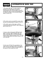
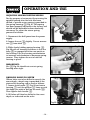
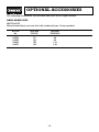
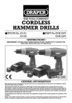
DRILL PRESS
■ STOCK No.65028
■ PART No.GD13/5C
• INSTRUCTIONS •
IMPORTANT: PLEASE READ THESE INSTRUCTIONS CAREFULLY TO ENSURE THE
SAFE AND EFFECTIVE USE OF THIS TOOL.
10/2001
GENERAL INFORMATION
This manual has been compiled by Draper Tools and is an integrated part of the power tool equipment, which
should be kept with the machine.
This manual describes the purpose for which this tool has been designed and contains all the necessary
information to ensure its correct and safe use.We recommend that this manual is read before any operation of
the machine, before performing any kind of adjustment to the machine, and prior to any maintenance tasks. By
following all the general safety instructions contained in this manual, it will ensure both machine and operator
safety, together with longer life of the tool itself.
All photographs and drawings in this manual are supplied by Draper Tools to help illustrate the operation of the
machine.
Whilst every effort has been made to ensure accuracy of information contained in this manual, the Draper Tool
policy of continuous improvement determines the right to make modifications without prior warning.
DRILL PRESS
■ STOCK No.65028
■ PART No. GD13/5C
CONTENTS:
Page No.
Declaration of Conformity..............................................................................................1
Specification/Guarantee ................................................................................................2
Power Supply .................................................................................................................3
General Safety Instructions ............................................................................................4
Additional Safety Rules ..................................................................................................5
Unpacking and Checking ..............................................................................................6
Getting to Know Your Drill Press ....................................................................................7
Assembly ..................................................................................................................8-10
Operation and Use ..................................................................................................11-15
Trouble Shooting..........................................................................................................15
Optional Accessories ...................................................................................................16
DECLARATION OF CONFORMITY
We
Draper Tools Ltd. Hursley Road, Chandler’s Ford, Eastleigh, Hampshire. SO53 1YF.
England.
Declare under our sole responsibility that the product:
Stock No:- 65028.
Part No:- GD13/5C.
Description:- Pillar Drill.
To which this declaration relates is in conformity with the following directive(s)
98/37/EC, 73/23/EEC & 89/336.
JOHN DRAPER
Managing Director
08/03/2001
-1-
SPECIFICATION
The Draper Tools policy of continuous improvement determines the right to change
specification without notice.
GD13/5C
65028
13mm
13mm
MT2
5 (600 - 2800rpm)
264mm
65mm
60mm
250mmØ
205 x 345mm
250W - (230V/50Hz)
740mm
33/35kg
70db(A)
Part No
Stock No
Drilling Capacity
Chuck Capacity
Spindle Taper
Speeds (RPM)
Swing
Spindle Travel
Column Diameter
Table Size
Base Size
Motor Size
Height
Nett Weight
Sound pressure level
ALWAYS WEAR EAR PROTECTION
GUARANTEE
Draper tools have been carefully tested and inspected before shipment and are
guaranteed to be free from defective materials and workmanship for a period of 12
months from the date of purchase except where tools are hired out when the guarantee
period is ninety days from the date of purchase.
Should the machine develop any fault, please return the complete tool to your nearest
authorized warranty repair agent or contact Draper Tools Limited, Chandler's Ford,
Eastleigh, Hampshire, SO53 1YF. England. Telephone: (023) 8026 6355.
If upon inspection it is found that the fault occurring is due to defective materials or
workmanship, repairs will be carried out free of charge. This guarantee does not apply
to normal wear and tear, nor does it cover any damage caused by misuse, careless or
unsafe handling, alterations, accident, or repairs attempted or made by any personnel
other than the authorised Draper warranty repair agent.
This guarantee applies in lieu of any other guarantee expressed or implied and
variations of its terms are not authorised.
Your Draper guarantee is not effective unless you can produce upon request a dated
receipt or invoice to verify your proof of purchase within the 12 month period.
Please note that this guarantee is an additional benefit and does not affect your
statutory rights.
Draper Tools Limited
-2-
POWER SUPPLY
CONNECTING YOUR MACHINE TO THE POWER SUPPLY: (230V)
To eliminate the possibility of an electric shock your machine has been fitted with a BS
approved, non rewireable moulded plug and cable which incorporates a fuse, the value
of which is indicated on the pin face of the plug. Should the fuse need to be replaced an
approved BS1362 fuse must be used of the same rating, marked thus
.
The fuse cover is detachable, never use the plug with the cover omitted. If a replacement
fuse cover is required, ensure it is of the same colour as that visible on the pin face of the
plug (i.e. red). Fuse covers are available from your Draper Tools stockist.
If the fitted plug is not suitable, it should be cut off and destroyed. *The end of the cable
should now be suitably prepared and the correct type of plug fitted. See below.
*WARNING:
A plug with bare flexible wires exposed is hazardous if engaged in a live power socket
outlet.
WARNING: THIS APPLIANCE MUST BE EARTHED.
The mains lead is coloured Green and Yellow - Earth, Blue – Neutral & Brown – Live.
As these colours may not correspond with the coloured markings identifying the
terminals in your plug, proceed as follows:
The wire which is coloured green and yellow must be connected to the terminal in your
plug marked with the letter ‘E’ or by the earth symbol
or coloured green or green
and yellow. The wire which is coloured blue must be connected to the terminal which is
marked with the letter ‘N’ or coloured black or blue. The wire which is coloured brown
must be connected to the terminal which is marked with the letter ‘L’ or coloured red or
brown.
EXTENSION LEAD CHART:
Extension lead sizes shown assure a voltage drop of not more than 5% at rated load of tool.
Ampere rating
(on Name plate)
3
6
13
1.0
1.0
1.0
1.25
1.5
1.25
1.5
1.5
1.5
2.5
Wire Size mm2
Extension cable length
7.5M
15M
22.5M
30M
40M
10
0.75
0.75
0.75
0.75
1.25
0.75
0.75
0.75
0.75
0.75
-3-
GENERAL SAFETY INSTRUCTIONS
FOR POWER TOOLS
WARNING
Please read the following instructions carefully, failure to do so could lead to serious personal injury.
IMPORTANT
Draper Tools Limited recommends that this machine should not be modified or used for any application other
than that for which it was designed. If you are unsure of its relative applications do not hesitate to contact us in
writing and we will advise you.
1.
2.
3.
4.
5.
6.
7.
8.
9.
10.
11.
12.
13.
14.
KNOW YOUR POWER TOOL
Read and understand the owner's manual and labels
affixed to the tool. Learn its application and limitations as
well as the specific potential hazards peculiar to this tool.
KEEP WORK AREA CLEAN
Cluttered areas and benches invite accidents. Floors must
not be slippery due to oil or sawdust.
AVOID DANGEROUS ENVIRONMENTS
Do not use power tools in damp or wet locations, or
expose them to rain. Keep work area well lit. Provide
adequate space surrounding the work area. Do not use in
environments with a potentially explosive atmosphere.
KEEP CHILDREN AWAY
All visitors should be kept a safe distance from work area.
STORED TOOLS
When not being used, all tools should be stored in a dry,
locked cupboard or out of the reach of children.
WEAR PROPER CLOTHING
Do not wear loose clothing, neckties or jewellery (rings,
wristwatches) to catch in moving parts. NONSLIP footwear
is recommended.Wear protective hair covering to contain
long hair. Roll long sleeves above the elbow.
USE SAFETY GOGGLES (Head Protection)
Wear CE approved safety goggles at all times. Normal
spectacles only have impact resistant lenses, they are
NOT safety glasses. Also, use face or dust mask if
application is dusty and ear protectors (plugs or muffs)
during extended periods of operation.
NOISE LEVELS
Some types of machines may have high noise levels when
working. In such cases ear protection must be worn.
VIBRATION LEVELS
Hand held power tools produce different vibration levels.
You should always refer to the specifications and relevant
Health and Safety guide.
DUST EXTRACTION
If your tool is fitted with a dust extraction fitting, always
ensure that it is connected and being used with a dust
extractor.Vacuum cleaners can be used if suitable for the
material being extracted.
PROTECT YOURSELF FROM ELECTRIC SHOCK
When working with power tools, avoid contact with any
earthed items (e.g. pipes, radiators, hobs and
refrigerators, etc.). If you are using a power tool in
extreme conditions (e.g. high humidity or generating
metal dust), always use an RCD (residual current device)
at the power socket.
STAY ALERT
Always watch what you are doing and use common sense.
Do not operate a power tool when you are tired or under
the influence of alcohol or drugs.
WHEN WORKING OUT OF DOORS
Only use extension leads designed for that purpose.
ACCESS TO MAINS SOCKET
If a stationary machine is fitted with a moulded plug and
cable, the machine should not be positioned so that
access to the mains socket is restricted.
15.
16.
17.
18.
19.
20.
21.
22.
23.
24.
25.
26.
27.
28.
29.
30.
DISCONNECT POWER TO THE TOOL
When not in use, before servicing and when changing
accessories such as cutters, etc.
AVOID ACCIDENTAL STARTING
Make sure the switch is in the OFF position before
plugging the machine into the power supply.
NEVER LEAVE MACHINE RUNNING UNATTENDED
Turn power off. Do not leave machine until it comes to a
complete stop.
DO NOT ABUSE THE CORD
Never carry the tool by the power cable or pull it from
the socket. Keep the power cable away from heat, oil and
sharp edges.
NEVER STAND ON TOOL
Serious injury could occur if the tool is tipped or if the
cutting tool is accidentally contacted. Do not store
materials above or near the tool, so that it is necessary to
stand on the tool to reach them.
CHECK DAMAGED PARTS
Check for damage to parts, breakage of parts, mountings
and any other conditions that may affect its operation.
A guard or other part that is damaged should be properly
repaired or replaced.
KEEP GUARDS IN PLACE
And in working order.
MAINTAIN TOOLS WITH CARE
Keep tools sharp and clean for the best and safest
performance. Follow instructions for lubricating and
changing accessories. All extension cables must be
checked at regular intervals and replaced if damaged.
Always keep the hand grips on the tool clean, dry and
free of oil and grease.
USE RECOMMENDED ACCESSORIES
Consult the owners manual for recommended
accessories. Follow the instructions that accompany the
accessories. The use of improper accessories may cause
hazards.
REMOVE ADJUSTING KEYS AND WRENCHES
Form a habit of checking to see that keys and adjusting
wrenches are removed from the tool before turning it on.
SECURE WORK
Use clamps or a vice to hold work. This frees both hands
to operate the tool.
DO NOT OVERREACH
Keep proper footing and balance at all times.
USE RIGHT TOOL
Do not force the tool or attachment to do a job for which it
was not designed.
DO NOT FORCE TOOL
It will do the job better and safer at the rate for which it
was designed.
DIRECTION OF FEED
Feed work into a blade or cutter against the direction of
rotation of the blade or cutter only.
WHEN DRILLING OR SCREWING INTO WALLS
Always make sure there is no danger of hitting any hidden
power cables, water or gas pipes in the wall.
IMPORTANT NOTE
Residual Risk. Although the safety instructions and operating manuals for our tools contain extensive
instructions on safe working with power tools, every power tool involves a certain residual risk which can not be
completely excluded by safety mechanisms. Power tools must therefore always be operated with caution !
-4-
ADDITIONAL SAFETY RULES FOR
DRILL PRESSES
5. CHECK to see that the chuck is
securely fastened to the spindle.
1. This drill press is intended for use
only with drill bits. The use of any
other accessories may be hazardous.
6. CAUTION
When practical, use a vice or clamps
to secure workpiece to avoid
workpiece rotating with the drill bit.
2. CHECK to see that the drill bit is
securely locked in the chuck.
3. CORRECT DRILLING SPEEDS
Important factors which determine the
best speed to use in any drill press
operation are:
(a) The smaller the drill the greater
the required r.p.m. (revolutions
per minute)
(b) In soft materials the speed should
be higher than for hard materials.
7. SECURE the tool to a workbench or
floor. If during operation there is any
tendency for the drill press to tip over,
slide or walk on the supporting
surface, the drill base must be secured
to the supporting surface with
fasteners through the holes located in
the drill press base.
4. MAKE sure that the chuck key is
removed before turning on power.
8. For your safety DO NOT wear gloves
when operating a drill press.
-5-
UNPACKING AND CHECKING CONTENTS
Carefully unpack the bench drill and all loose items from the carton. Illustrated below
is the bench drill and all loose items. NOTE: Some loose parts may be packed inside the
pulley cover.
Fig.1.
Now referring to Fig.1. carefully check that all the parts are present.
Please contact the stockist where your purchase was made if you have any enquiries, eg
problems with assembly, apparent missing/damaged parts, help with accessories
available or technical advice or alternatively call the Draper Helpline on (023) 8049 4344.
-6-
GETTING TO KNOW YOUR
DRILL PRESS
✖✌
✗✌
✘✌
✕✛✌
✕✚✌
✚✌
✕✌
✙✌
✛✌
✕✙✌
✜✌
✕✜✌
✕✘✌
✢✌
✕✕✌
✕✔✌
✕✗✌
✕✖✌
✕✌
✖✌
✗✌
✘✌
✙✌
✚✌
✛✌
✜✌
✢✌
MOTOR
PULLEY COVER
MOTOR PULLEY
SPINDLE PULLEY
SPECIFICATION LABEL
DOWN FEED ASSEMBLY
CHUCK GUARD
CHUCK
TABLE
✕✔✌
✕✕✌
✕✖✌
✕✗✌
✕✘✌
✕✙✌
✕✚✌
✕✛✌
✕✜✌
TABLE LOCKING HANDLE
COLUMN
BASE
RACK
TABLE RISE AND FALL HANDLE
RACK SECURING RING
NO-VOLT TYPE ON/OFF SWITCH
DRIVE BELT - TENSION ADJUSTER
RISE AND FALL LOCKING HANDLE
-7-
ASSEMBLY
ASSEMBLING THE DRILL PRESS
1. Secure column ✪✌ to base ✫✌ using the
four bolts ✬✌. Loosen grub screw and
remove collar ✭✌ along with the rack ✮✌.
Fig.2.
✭✌
✮✌
✪✌
✬✌
✫✌
2. Locate worm gear ✯✌ into hole ✰✌ as
shown in Fig.3.
Fig.3.
3. Place rack ✱✌ in position in table bracket
✲✌, as shown in Fig.4. and slide onto column.
Fig.4.
✯✌
✰✌
✱✌
✲✌
-8-
ASSEMBLY
4. Ease table bracket and rack all the way down
onto the column. Replace collar ✳✌ and retighten the grub screw, locking rack ✴✌ into
place.
Fig.5.
✳✌
✴✌
5. Slide table ✵✌ into the table bracket as
shown in Fig.6 and lock into place using the
table locking handle ✶✌.
Fig.6.
✵✌
✸✌
6. Fix table raising handle ✷✌ and bracket
locking handle ✸✌ as shown in Fig 6.
✶✌
7.Place the drill press head ✹✌ onto column as
far as it will go (seek assistance as it is heavy).
Align the head and table to drill press base and
tighten the two head locking screws ✺✌ as
shown in Fig 7.
✷✌
Fig.7.
✹✌
✺✌
-9-
ASSEMBLY
8. Screw the three downfeed handles ✻✌ into
the three holes located in the pinion shaft as
shown in Fig 8.
✻✌
Fig.8.
9. Making sure that the chuck ✼✌ is opened to
its capacity, place it down on a bench. Clean
any excess grease off the large end of the
spindle ✽✌. Insert the taper into the back of
the chuck and with a scrap piece of timber
and a hammer firmly tap them together.
✽✌
✼✌
Fig.9.
10. Loosen the nut and bolt ✾✌ Fig.10 and
slide the chuck guard ✿✌ up onto the collar
❀✌. Tighten the nut and bolt and lift the guard
into the upright position.
11. Now clean the other end of the arbor ❁✌
Fig.11 from grease and offer it up to the
spindle ❂✌. Rotate the arbor and chuck until
the flats on the arbor engage into the spindle
❂✌. Then firmly tap once using a hammer and
scrap piece of timber. Should it be required,
removal of the arbor from the spindle is
achieved by lowering the spindle, and with the
depth gauge, lock it in the down position. On
the side of the spindle is a hole which exposes
the top of the arbor (if this cannot be seen
fully, rotate the chuck slightly). Now using the
tool provided, tap into the hole forcing the
arbor down and out.
- 10 -
❀✌
✿✌
✾✌
Fig.10.
Fig.11.
❁✌
❂✌
OPERATION AND USE
NO-VOLT ON/OFF SWITCH: (Fig 12)
The drill is fitted with a no-volt switch with an
emergency shut-off cover ❃✌.
Fig.12.
In the event of an emergency, closing the cover
firmly will cause the stop button to be
triggered, thus stopping the machine. To reopen the cover, the red button requires sliding
up which in turn will release the stop button.
In the event of a power failure the drill press
will have to be manually re-started.
To switch the drill press on, lift up the sprung
cover and push the button marked ✲✌.
To switch the drill press off, lift up the sprung
cover and push the button marked ✸✌.
To switch the drill press off in an emergency
strike the cover firmly which will trigger the
✸✌button.
- 11 -
❃✌
OPERATION AND USE
SPINDLE SPEEDS
Five spindle speeds of: 600, 890, 1360, 2016,
and 2800rpm are available with your drill. The
highest speed is obtained when the belt is on
the largest step of the motor pulley and the
smallest step of the spindle pulley as shown in
Fig. 13.
Fig.13.
CHANGING SPEEDS AND ADJUSTING
BELT TENSION
1. Disconnect the drill press from the power
supply.
2. Lift up the belt and pulley guard ✪✌ Fig. 14.
Fig.14.
3. Release the belt tension by loosening
locking knob ✫✌ Fig. 15 and moving tension
lever ✬✌ towards the front of the drill press.
4. With the belt slack, position the belt ✭✌ on
the desired steps of the motor and spindle
pulleys for the correct speed as shown
in Fig. 15.
Fig.15.
Spindle
Motor
✪✌
✭✌
✬✌
✫✌
5. After the belt is positioned on the desired
steps of the pulleys, pivot the motor away from
the drill press head until the belt is properly
tensioned and tighten tension lock knob ✮✌
Fig. 16. The belt should be just tight enough to
prevent slipping. Excessive tension will
reduce the life of the belt, pulleys and
bearings. Correct tension is obtained when
the belts ✯✌ can be flexed about 25mm out of
line midway between the pulleys using light
finger pressure.
- 12 -
Fig.16.
✯✌
✮✌
OPERATION AND USE
1. The table ✰✌ Fig. 17 can be raised or
lowered on the drill press column by
loosening the table clamp handle ✱✌ and
turning the table raising and lowering handle
✲✌. After the table is at the desired height,
tighten handle ✱✌.
✰✌
✱✌
✲✌
Fig.17.
2. The table can be rotated 360º on the table
bracket by loosening lock handle ✳✌ Fig. 18.
3. The table can be tilted right or left by
unscrewing and removing the table alignment
grub screw Fig. 18.
✳✌
Fig.18.
4. Loosen table locking bolt ✴✌(Fig.19) tilt
table to desired angle. Retighten bolt ✴✌.
When returning table to the level position
replace table alignment grub screw. This will
automatically position the table surface at 90º
to the spindle.
✴✌
Fig.19.
5. A tilt scale ✵✌ Fig. 20 is provided on the
table bracket casting to indicate the degree
of tilt. A cursor line ✶✌ is also provided on
the table to line up with the scale.
✶✌
Fig.20.
- 13 -
✵✌
OPERATION AND USE
ADJUSTING SPINDLE RETURN SPRING
For the purpose of automatically returning the
spindle upward after the hole has been
drilled, a spindle return spring is provided in
the spring housing ✷✌ Fig. 21. This spring
has been properly adjusted at the factory and
should not be disturbed unless absolutely
necessary. To adjust the return spring,
proceed as follows:
Fig.21.
✸✌
✹✌
✷✌
1. Disconnect the drill press from the power
supply.
2. Loosen the nut ✸✌ slightly. Do not remove
nut ✸✌ from shaft ✹✌.
✻✌
3. While firmly holding spring housing ✺✌
Fig. 22 pull out housing and rotate it until the
boss ✻✌ is engaged with the next notch on
the housing. Turn the housing anticlockwise
to increase and clockwise to decrease spring
tension. Then tighten the nut to hold the
housing in place.
Fig.22.
✺✌
✼✌
IMPORTANT:
Nut ✼✌ Fig. 24 should not contact spring
housing when tight.
DRILLING HOLES TO DEPTH
Where holes are to be drilled to exactly the
same depth, a depth stop is provided in the
pinion shaft housing and is used as follows:
1. Loosen lock handle ✾✌ Fig. 23 and rotate
housing ✽✌ until the pointer ✿✌ lines up with
the depth you wish to drill on the scale ❀✌.
Then tighten lock handle ✾✌.
2. All holes will then be drilled to the exact
depth, as indicated on the scale.
✾✌
❀✌
✿✌
Fig.23.
- 14 -
✽✌
OPERATION AND USE
The following directions will give the inexperienced operator a start on common drill press
operations. Use scrap material for practice to get the feel of the machine before attempting
regular work.
CORRECT DRILLING SPEEDS
Factors which determine the best speed to use in any drill press operations are:
Type of material being worked,
Size of hole,
Type of drill or other cutter,
Quality of cut desired.
The smaller the drill, the greater the required r.p.m. In soft materials the speed should be
higher than for hard materials.
DRILLING METAL
Use clamps to hold the workpiece when drilling in metal. The workpiece should never be
held in the hand; the drill may snatch the workpiece at any time, especially when breaking
through. If the workpiece is twisted out of the operator’s hand, they may be injured.
The workpiece must be clamped firmly while drilling; any tilting, twisting or shifting results
not only in a rough hole, but also increases drill breakage. For flat work, lay the workpiece
on a wooden base and clamp it firmly down against the table to prevent it from moving. If
the workpiece is of irregular shape and cannot be laid flat on the table, it should be securely
blocked and clamped using vee-blocks, clamps or a machine vice.
TROUBLE SHOOTING
WARNING: FOR YOUR OWN SAFETY ALWAYS TURN THE MAIN SWITCH ON THE MACHINE “OFF” AND
REMOVE THE PLUG FROM THE POWER SUPPLY BEFORE CARRYING OUT ANY MAINTENANCE OR
TROUBLESHOOTING.
TROUBLE
PROBABLE CAUSE
REMEDY
Noisy Operation
1. Incorrect belt tension
2. Dry spindle
3. Loose spindle pulley or motor pulley
1. Adjust tension
2. Lubricate spindle with grease (ISO VG68)
3. Tighten set screws in pulleys
1. Incorrect speed
2. Swarf not coming out of hole
3. Blunt bit
4. Feeding too slow
5. Not lubricated
6. Bit running backwards
1. Change speed
2. Retract bit frequently to clear swarf
3. Sharpen or replace bit
4. Feed fast enough to allow drill to cut
5. Lubricate bit
6. Check motor rotation
Excessive drill run-out
or wobble
1. Bent bit
2. Worn spindle bearings
3. Bit not properly installed in chuck
4. Chuck not properly installed
1. Use a straight bit
2. Replace
3. Install bit centrally
4. Refit chuck properly
Drill binds in workpiece
1. Workpiece pinching bit or excessive
feed pressure
2. Improper belt tension
1. Support or clamp workpiece
2. Adjust tension
Bit burns or smokes
- 15 -
OPTIONAL ACCESSORIES
The following accessories are available from your local Draper stockist.
DRILL PRESS VICES
PART No.DPV
Manufactured from cast iron with fully hardened jaws. Carton packed.
STOCK
No.
JAW-MM
WIDTH
JAW-MM
OPENING
54634
54635
54636
54637
75
100
120
145
80
90
118
140
- 16 -
NOTES
- 17 -
NOTES
- 18-
DRAPER TOOLS LIMITED,
Hursley Road, Chandler's Ford, Eastleigh, Hants. SO53 1YF. U.K.
Helpline: (023) 8049 4344.
Sales Desk: (023) 8049 4333.
General Enquiries: (023) 8026 6355.
Fax: (023) 8026 0784.
www.draper.co.uk
e-mail: [email protected]
YOUR DRAPER STOCKIST
©Published by Draper Tools Ltd.
No part of this publication may be reproduced,
stored in a retrieval system or transmitted in
any form or by any means, electronic, mechanical
photocopying, recording or otherwise without prior
permission in writing from Draper Tools Ltd.