1
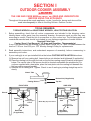
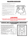
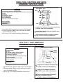
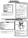
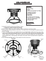
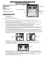
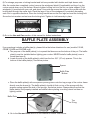
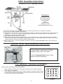
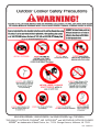
English Outdoor cookers cast cooker Assembly Instructions and use and care Manual MODEL/serial # __________ THE INSTRUCTION MANUAL CONTAINS IMPORTANT INFORMATION NECESSARY FOR THE PROPER ASSEMBLY AND SAFE USE OF THE APPLIANCE. READ AND FOLLOW ALL WARNINGS AND INSTRUCTIONS BEFORE ASSEMBLING AND USING THE APPLIANCE. FOLLOW ALL WARNINGS AND INSTRUCTIONS WHEN USING THE APPLIANCE. KEEP THIS MANUAL FOR FUTURE REFERENCE. Metal Fusion, Inc. 712 St. George Avenue. Jefferson, LA 70121 If you have any problems or questions Call Us Toll Free at 1-800-783-3885 7:30 A.M. to 3:30 P.M. CST • Monday through Friday (504) 736-0201 www.kingkooker.com Failure to follow these instructions and Warnings could result in fire, explosion, burn hazard or carbon monoxide poisoning which could cause Property Damage, Personal Injury or Death. danger for your safety If you smell gas: 1.Shut off gas to the appliance. 2.Extinguish any open flame. 3. If odor continues, keep away from the appliance and immediately call your Fire Department. FAILURE TO FOLLOW THESE INSTRUCTIONS COULD RESULT IN FIRE OR EXPLOSION WHICH COULD CAUSE PROPERTY DAMAGE, PERSONAL INJURY OR DEATH. danger 1.Never operate this appliance unattended. 2.Never operate this appliance within 10 feet (3.05m) of any structure, combustible material or other gas cylinder. Do not locate this appliance under ANY overhead construction. 3.Only use propane burning units outdoors. Risks include fire and carbon monoxide fumes. Lack of ventilation can cause injury or death. 4.Never operate this appliance within 25 feet (7.5m) of any flammable liquids or vapors. 5.Do not fill cooking vessel beyond maximum fill line (if applicable). 6. When cooking with oil/grease, always use the thermometer provided and never allow the oil/grease to get hotter than 350°F (177°C). If the temperature exceeds 350°F (177°C) or if oil begins to smoke, immediately turn the burner or gas supply OFF. 7. Heated liquids and equipment remain at scalding temperatures long after the cooking process. Never touch cooking appliance until liquids have cooled to 100°F (38°C) or less. 8. If a fire should occur, keep away from the appliance and immediately call your Fire Department. Do not attempt to extinguish an oil/ grease fire with water. When cooking, have a Type BC or ABC fire extinguisher readily available. A Type BC or ABC fire extinguisher may, in some circumstances, contain the fire. Failure to follow these instructions and warnings could result in fire, explosion, burn hazard or carbon monoxide poisoning which could cause Property Damage, Personal Injury or Death. 2 Read and Understand before using this product Throughout this manual the words appliance, cooker, fryer/boiler, burner and stove will be used interchangeably to refer to the King Kooker® Outdoor Cooker. 1)This is an ATTENDED appliance. Do NOT leave this appliance unattended while the burner is lit or while heating oil, grease, water or cooking food. Monitor the appliance when hot after use [oil, grease or water above 100° F (38°C)]. Heated liquid and equipment can remain at scalding temperatures long after cooking has ended. 2) Keep children, pets and unauthorized persons away from the appliance at all times. 3)The use of alcohol, prescription or non-prescription drugs may impair your ability to properly assemble or safely operate this appliance. Do NOT assemble or operate this appliance if using alcohol, prescription or nonprescription drugs. 4)This appliance is for OUTDOOR use only. Do NOT use in a building, garage, tent or any other enclosed area. Do NOT use in or on a recreational vehicle or boat. NEVER use this appliance as a heater. 5)Do not locate this appliance under any overhead construction. Keep a minimum clearance of 10 ft. (3.05m) from the sides, front and back of the appliance to ANY construction. Keep the area clear of any combustible material. Do not use on or under any apartment or condo balcony or deck. 6) When cooking, the fryer/boiler must be on a level, stable, noncombustible surface such as brick, concrete or dirt. Not suitable are surfaces such as wood, asphalt or plastic which may burn, blister or melt. 7)Check all cooker fittings for leaks before each use. Keep the fuel supply hose away from any heated surfaces. Only the LP hose/regulator assembly specified by Metal Fusion, Inc. should be used with this appliance. 8)This appliance is not for frying turkeys. 9) When cooking with oil or grease, the thermometer provided MUST be used. Follow instructions in this manual for proper installation and use of thermometer. If the thermometer supplied with the fryer/boiler has been lost or damaged, a replacement thermometer specified by Metal Fusion, Inc. shall be obtained before using the appliance. 10) If the temperature of cooking oil exceeds 350°F (177°C) or if oil begins to smoke, immediately turn the burner or gas supply OFF and wait for the temperature to decrease to less than 350°F (177°C) before relighting burner according to the instructions in this manual. 11) When cooking with oil/grease, have a Type BC or ABC fire extinguisher readily available. In the event of an oil/grease fire, do not attempt to extinguish with water. Immediately call the Fire Department. A Type BC or ABC fire extinguisher may, in some circumstances, contain the fire. 12)NEVER overfill the cooking pot with oil, grease or water. Follow instructions in this manual for establishing proper oil, grease or water levels. 3 13) Introduction of water or ice from any source into the oil/grease may cause overflow and severe burns from hot oil and water splatter. When frying with oil/ grease, all food products MUST be completely thawed and towel dried before being immersed in the fryer. 14)Never drop food or accessories into hot cooking liquid. Lower food and accessories slowly into the cooking liquid in order to prevent splashing or overflow. When removing food from the appliance, care shall be taken to avoid burns from hot cooking liquids. 15)This appliance and pot, including handles and lids, gets dangerously hot in use. Use well-insulated pot holders or oven mitts for protection from hot surfaces or splatter from cooking liquids. Safety goggles are also recommended to protect you from oil splatter. The oil remains dangerously hot hours after use. 16)Do NOT place an empty cooking vessel on the appliance while in operation. Use caution when placing anything in the cooking vessel while the appliance is in operation. Never use a cooking vessel larger than the capacity and diameter specified in this manual. 17) In the event of rain, snow, hail, sleet or other forms of precipitation while cooking with oil/grease, cover the cooking vessel immediately and turn off the appliance burners and gas supply. Do not attempt to move the appliance or cooking vessel. 18)Do NOT move the appliance when in use. Allow the cooking vessel to cool to 100°F (38°C) before moving or storing. 19) Avoid bumping of or impact with the appliance to prevent contact with hot appliance, spillage or splashing of hot cooking liquid. 20)See Use and Care section for LP Gas Cylinder Information. A 20 pound (9 kg) cylinder should be used with this cooker. The LP-gas supply cylinder used must have a protective collar and must be constructed and marked in accordance with the specifications for LP-gas cylinders of the U. S. Department of Transportation (DOT) or the National Standard of Canada, Can/CSA-B339, Cylinders, Spheres and Tubes for the Transportation of Dangerous Goods. Do not store a spare LP-gas cylinder under or near this appliance. Never fill the cylinder beyond 80% full. For proper vapor withdrawal, the 20 lb. (9 kg) cylinder should be used in the proper upright position. Cylinder must be turned off while not in use. Failure to follow these instructions and warnings could result in fire or explosion which could cause property damage, personal injury or death. 21)This appliance is not intended for commercial use. 22)Use King Kooker® appliances only in accordance with state and local ordinances, or in the absence of local codes, with the National Fuel Gas Code, ANSIZ223.1/ NFPA 54, Storage and Handling of Liquefied Petroleum Gases, ANSI/NFPA 58 or CSA B149.1, Natural Gas and Propane Installation Code. Failure to follow these instructions and warnings could result in fire, explosion, burn hazard or carbon monoxide poisoning which could cause Property Damage, Personal Injury or Death. 4 Read and understand all instructions before using your king kooker® product table of contents Warnings. . . . . . . . . . . . . . . . . . . . . . . . . . . . . . . . . . . . . . . . . . . . . . . . . . . . . . . . . . . . . . . . . . . . . . . . . . . . . . . . . . . . . . . . . . . . . . . . . . . . . . . . . . . . . . . . . . . . . . . 2-4 Table of Contents. . . . . . . . . . . . . . . . . . . . . . . . . . . . . . . . . . . . . . . . . . . . . . . . . . . . . . . . . . . . . . . . . . . . . . . . . . . . . . . . . . . . . . . . . . . . . . . . . . . . . . . . . . . . . . . . . . . . . . . 5 Warranty. . . . . . . . . . . . . . . . . . . . . . . . . . . . . . . . . . . . . . . . . . . . . . . . . . . . . . . . . . . . . . . . . . . . . . . . . . . . . . . . . . . . . . . . . . . . . . . . . . . . . . . . . . . . . . . . . . . . . . . . . . . . . . . 6 Owner’s Registration . . . . . . . . . . . . . . . . . . . . . . . . . . . . . . . . . . . . . . . . . . . . . . . . . . . . . . . . . . . . . . . . . . . . . . . . . . . . . . . . . . . . . . . . . . . . . . . . . . . . . . . . . . . . . . . . . . . 7-8 Section I - King Kooker ® Outdoor Cooker Assembly. . . . . . . . . . . . . . . . . . . . . . . . . . . . . . . . . . . . . . . . . . . . . . . . . . . . . . . . . . . . . . . . . . . . . . . . . . . . . . . . . . . . . . . . . 9 Casting Installation . . . . . . . . . . . . . . . . . . . . . . . . . . . . . . . . . . . . . . . . . . . . . . . . . . . . . . . . . . . . . . . . . . . . . . . . . . . . . . . . . . . . . . . . . . . . . . . . . . . . . . . . . . . . . . . . 9 Outdoor Cooker Assembly Instructions. . . . . . . . . . . . . . . . . . . . . . . . . . . . . . . . . . . . . . . . . . . . . . . . . . . . . . . . . . . . . . . . . . . . . . . . . . . . . . . . . . . . . . . . . . . . . . 9-11 CS8T Assembly Instructions. . . . . . . . . . . . . . . . . . . . . . . . . . . . . . . . . . . . . . . . . . . . . . . . . . . . . . . . . . . . . . . . . . . . . . . . . . . . . . . . . . . . . . . . . . . . . . . . . . . . . . . . 12 KKDFF30T / 8005 / 82-82TKD Assembly Instructions . . . . . . . . . . . . . . . . . . . . . . . . . . . . . . . . . . . . . . . . . . . . . . . . . . . . . . . . . . . . . . . . . . . . . . . . . . . . . . . . . . . . 12 18KD, 21KD, SS21PKD and 24WC Assembly Instructions . . . . . . . . . . . . . . . . . . . . . . . . . . . . . . . . . . . . . . . . . . . . . . . . . . . . . . . . . . . . . . . . . . . . . . . . . . . . . . 13 1212, 1214, 1642, and 2616 Assembly Instructions. . . . . . . . . . . . . . . . . . . . . . . . . . . . . . . . . . . . . . . . . . . . . . . . . . . . . . . . . . . . . . . . . . . . . . . . . . . . . . . . . . . . . . 13 5012, 5212 and 1015 Assembly Instructions. . . . . . . . . . . . . . . . . . . . . . . . . . . . . . . . . . . . . . . . . . . . . . . . . . . . . . . . . . . . . . . . . . . . . . . . . . . . . . . . . . . . . . . . . . . 14 1644 and 1645 Assembly Instructions. . . . . . . . . . . . . . . . . . . . . . . . . . . . . . . . . . . . . . . . . . . . . . . . . . . . . . . . . . . . . . . . . . . . . . . . . . . . . . . . . . . . . . . . . . . . . . . . 14 1700, 1720 and 1740 Assembly Instructions. . . . . . . . . . . . . . . . . . . . . . . . . . . . . . . . . . . . . . . . . . . . . . . . . . . . . . . . . . . . . . . . . . . . . . . . . . . . . . . . . . . . . . . . . . . 15 High Pressure Units with Snap On Legs Assembly Instructions. . . . . . . . . . . . . . . . . . . . . . . . . . . . . . . . . . . . . . . . . . . . . . . . . . . . . . . . . . . . . . . . . . . . . . . . . . 16-17 Baffle Plate Assembly . . . . . . . . . . . . . . . . . . . . . . . . . . . . . . . . . . . . . . . . . . . . . . . . . . . . . . . . . . . . . . . . . . . . . . . . . . . . . . . . . . . . . . . . . . . . . . . . . . . . . . . . . . . . . 17 CS01 Assembly Instructions. . . . . . . . . . . . . . . . . . . . . . . . . . . . . . . . . . . . . . . . . . . . . . . . . . . . . . . . . . . . . . . . . . . . . . . . . . . . . . . . . . . . . . . . . . . . . . . . . . . . . . . . 18 1803PKP Work Table Assembly Instructions. . . . . . . . . . . . . . . . . . . . . . . . . . . . . . . . . . . . . . . . . . . . . . . . . . . . . . . . . . . . . . . . . . . . . . . . . . . . . . . . . . . . . . . . . . . 18 Fry Basket Assembly. . . . . . . . . . . . . . . . . . . . . . . . . . . . . . . . . . . . . . . . . . . . . . . . . . . . . . . . . . . . . . . . . . . . . . . . . . . . . . . . . . . . . . . . . . . . . . . . . . . . . . . . . . . . . . 18 Section II - Use and Care of King Kooker® Outdoor Cookers and Accessories. . . . . . . . . . . . . . . . . . . . . . . . . . . . . . . . . . . . . . . . . . . . . . . . . . . . . . . . . . . . . . . . . . 19 Thermometer Instructions and Safety Precautions for Deep Frying with Outdoor Cookers . . . . . . . . . . . . . . . . . . . . . . . . . . . . . . . . . . . . . . . . . . . . . . . . . . . . . . 19 Determining Proper Fill Levels for Cooking Vessels. . . . . . . . . . . . . . . . . . . . . . . . . . . . . . . . . . . . . . . . . . . . . . . . . . . . . . . . . . . . . . . . . . . . . . . . . . . . . . . . . . . . . 19 LP Gas Cylinder Information. . . . . . . . . . . . . . . . . . . . . . . . . . . . . . . . . . . . . . . . . . . . . . . . . . . . . . . . . . . . . . . . . . . . . . . . . . . . . . . . . . . . . . . . . . . . . . . . . . . . . . . . 20 Connection Instructions . . . . . . . . . . . . . . . . . . . . . . . . . . . . . . . . . . . . . . . . . . . . . . . . . . . . . . . . . . . . . . . . . . . . . . . . . . . . . . . . . . . . . . . . . . . . . . . . . . . . . . . . . . . 20 Leak Test Instructions. . . . . . . . . . . . . . . . . . . . . . . . . . . . . . . . . . . . . . . . . . . . . . . . . . . . . . . . . . . . . . . . . . . . . . . . . . . . . . . . . . . . . . . . . . . . . . . . . . . . . . . . . . . . . 20 Placement Instructions. . . . . . . . . . . . . . . . . . . . . . . . . . . . . . . . . . . . . . . . . . . . . . . . . . . . . . . . . . . . . . . . . . . . . . . . . . . . . . . . . . . . . . . . . . . . . . . . . . . . . . . . . . . . 21 Lighting and Operating Instructions. . . . . . . . . . . . . . . . . . . . . . . . . . . . . . . . . . . . . . . . . . . . . . . . . . . . . . . . . . . . . . . . . . . . . . . . . . . . . . . . . . . . . . . . . . . . . . . . 22-23 Turning Off and Storing the Cooker after Use. . . . . . . . . . . . . . . . . . . . . . . . . . . . . . . . . . . . . . . . . . . . . . . . . . . . . . . . . . . . . . . . . . . . . . . . . . . . . . . . . . . . . . . . . . 23 Maintenance Of Outdoor Cookers And Accessories. . . . . . . . . . . . . . . . . . . . . . . . . . . . . . . . . . . . . . . . . . . . . . . . . . . . . . . . . . . . . . . . . . . . . . . . . . . . . . . . . . . . . 24 Caring For Aluminum and Cast Iron Cookware. . . . . . . . . . . . . . . . . . . . . . . . . . . . . . . . . . . . . . . . . . . . . . . . . . . . . . . . . . . . . . . . . . . . . . . . . . . . . . . . . . . . . . . . . 25 Information Regarding Cooking Oil. . . . . . . . . . . . . . . . . . . . . . . . . . . . . . . . . . . . . . . . . . . . . . . . . . . . . . . . . . . . . . . . . . . . . . . . . . . . . . . . . . . . . . . . . . . . . . . . . . 25 Section III - Recipes. . . . . . . . . . . . . . . . . . . . . . . . . . . . . . . . . . . . . . . . . . . . . . . . . . . . . . . . . . . . . . . . . . . . . . . . . . . . . . . . . . . . . . . . . . . . . . . . . . . . . . . . . . . . . . . . . . . . 26 Boiled Seafood. . . . . . . . . . . . . . . . . . . . . . . . . . . . . . . . . . . . . . . . . . . . . . . . . . . . . . . . . . . . . . . . . . . . . . . . . . . . . . . . . . . . . . . . . . . . . . . . . . . . . . . . . . . . . . . . . . 26 Blackened Fish. . . . . . . . . . . . . . . . . . . . . . . . . . . . . . . . . . . . . . . . . . . . . . . . . . . . . . . . . . . . . . . . . . . . . . . . . . . . . . . . . . . . . . . . . . . . . . . . . . . . . . . . . . . . . . . . . . 26 Barbecued Shrimp . . . . . . . . . . . . . . . . . . . . . . . . . . . . . . . . . . . . . . . . . . . . . . . . . . . . . . . . . . . . . . . . . . . . . . . . . . . . . . . . . . . . . . . . . . . . . . . . . . . . . . . . . . . . . . . 26 King Kooker® Beans . . . . . . . . . . . . . . . . . . . . . . . . . . . . . . . . . . . . . . . . . . . . . . . . . . . . . . . . . . . . . . . . . . . . . . . . . . . . . . . . . . . . . . . . . . . . . . . . . . . . . . . . . . . . . 27 King Kooker® Jambalaya. . . . . . . . . . . . . . . . . . . . . . . . . . . . . . . . . . . . . . . . . . . . . . . . . . . . . . . . . . . . . . . . . . . . . . . . . . . . . . . . . . . . . . . . . . . . . . . . . . . . . . . . . . 27 Fried Seafood. . . . . . . . . . . . . . . . . . . . . . . . . . . . . . . . . . . . . . . . . . . . . . . . . . . . . . . . . . . . . . . . . . . . . . . . . . . . . . . . . . . . . . . . . . . . . . . . . . . . . . . . . . . . . . . . . . . 27 Fried Chicken . . . . . . . . . . . . . . . . . . . . . . . . . . . . . . . . . . . . . . . . . . . . . . . . . . . . . . . . . . . . . . . . . . . . . . . . . . . . . . . . . . . . . . . . . . . . . . . . . . . . . . . . . . . . . . . . . . . 27 Fried Onion Rings. . . . . . . . . . . . . . . . . . . . . . . . . . . . . . . . . . . . . . . . . . . . . . . . . . . . . . . . . . . . . . . . . . . . . . . . . . . . . . . . . . . . . . . . . . . . . . . . . . . . . . . . . . . . . . . . 28 Fried Mushrooms . . . . . . . . . . . . . . . . . . . . . . . . . . . . . . . . . . . . . . . . . . . . . . . . . . . . . . . . . . . . . . . . . . . . . . . . . . . . . . . . . . . . . . . . . . . . . . . . . . . . . . . . . . . . . . . . 28 King Kooker® Wings . . . . . . . . . . . . . . . . . . . . . . . . . . . . . . . . . . . . . . . . . . . . . . . . . . . . . . . . . . . . . . . . . . . . . . . . . . . . . . . . . . . . . . . . . . . . . . . . . . . . . . . . . . . . . 28 Steamed Clams and Mussels. . . . . . . . . . . . . . . . . . . . . . . . . . . . . . . . . . . . . . . . . . . . . . . . . . . . . . . . . . . . . . . . . . . . . . . . . . . . . . . . . . . . . . . . . . . . . . . . . . . . . . . 28 Steamed Crab, Shrimp, and Lobster. . . . . . . . . . . . . . . . . . . . . . . . . . . . . . . . . . . . . . . . . . . . . . . . . . . . . . . . . . . . . . . . . . . . . . . . . . . . . . . . . . . . . . . . . . . . . . . . . 28 Section IV - Frequently Asked Questions . . . . . . . . . . . . . . . . . . . . . . . . . . . . . . . . . . . . . . . . . . . . . . . . . . . . . . . . . . . . . . . . . . . . . . . . . . . . . . . . . . . 29 5 Metal Fusion, Inc. Limited One-Year Warranty What this warranty covers This warranty covers all components of this outdoor cooker to be free from defects in materials and workmanship, with the exceptions stated below. How long coverage lasts This warranty runs for one year from the date of purchase. Please keep your receipt with this manual for future reference. what is not covered This warranty does not cover the following: Incidental and Consequential Damages. This warranty does not cover incidental and consequential damages arising in any way out of the use of this outdoor cooker. The liability of Metal Fusion, Inc. is, in any event, limited to the amount of the original purchase price of this outdoor cooker, and remains in force only as long as the product remains in its original, as-built configuration. Some states do not allow the exclusion or limitation of incidental or consequential damages, so the above limitation or exclusion may not apply to you. Neglectful Operation. This warranty does not cover any loss or damage arising in any way due to the negligent operation of this outdoor cooker. Altered, Repaired or Misused Equipment. This warranty does not cover any loss or damage arising in any way out of the use of this outdoor cooker when it has been altered, repaired by persons other than Metal Fusion, Inc., or when it has been abused or misused, or when it has been used other than in accordance with the manufacturer’s operating instructions, including, without limitation, any damage to the consumer’s pots because they were placed on a lit cooker while the pot is empty. Other Assumed Responsibilities. Unless otherwise provided by law, this warranty does not cover any responsibility or liability arising in any way out of the use of this product where that responsibility or liability was purportedly assumed by any other person or agent. Paint, Discoloration, and Rust. This warranty does not cover the paint on the outdoor cooker, as in a normal use of the outdoor cooker, the paint will be burned off. Nor does this warranty cover discoloration or rust to the cooker as these occurrences are part of the cooker’s normal wear and tear. What metal fusion, inc. will do Metal Fusion, Inc. will repair or replace any outdoor cooker that proves to be defective in materials or workmanship. In the event repair is not possible or economically feasible, Metal Fusion, Inc. will replace your outdoor cooker with an identical or substantially equivalent outdoor cooker. Metal Fusion, Inc. will perform this service at no charge to you, except for the actual cost of shipping and handling the outdoor cooker or replacement parts. How to get service In the event you have a problem or malfunction with your outdoor cooker, simply call Metal Fusion, Inc. at (800) 783-3885. how state law applies This warranty gives you specific rights, and you may have other rights which vary from state to state. 6 Owner’s Registration Dear Customer, Thank you for purchasing a King Kooker®! Please take a moment to fill out your registration form and return it to us. We are always happy to hear suggestions and comments from our customers about our products. Completion of this registration allows us to contact you if the need arises. Please keep your receipt with your instruction manual. It will be necessary as a proof of purchase for us to help you if there is a problem with your cooker. Name:___________________________________________________________________ E-Mail: __________________________________________________________________ Address:_________________________________________________________________ ________________________________________________________________________ ________________________________________________________________________ Telephone:_ _____________________________________________________________ Model#_ ________________________________________________________________ Date of Purchase_________________________________________________________ Place of Purchase________________________________________________________ Price Paid_ ______________________________________________________________ Was this a gift _____ or did you _____ purchase it yourself? ________________________________________________________________________ ________________________________________________________________________ CUT HERE Comments: ________________________________________________________________________ ________________________________________________________________________ A SATISFIED CUSTOMER IS OUR MAIN GOAL. If you have any questions or problems, please call us at 1-800-783-3885 before returning the product to the point of purchase. Please have your receipt available when calling. Thank you, Enjoy your cooking experience. 7 TAPE HERE FOLD ________________________ ________________________ ________________________ Place Stamp Here Metal Fusion, Inc. 712 St. George Avenue Jefferson, LA 70121 FOLD 8 section I outdoor cooker assembly The use and care manual must be read and understood before using the appliance Throughout this manual the words appliance, cooker, fryer/boiler, burner and stove will be used interchangeably to refer to the King Kooker® Outdoor Cooker. TOOLS REQUIRED: TORQUE WRENCH or ADJUSTABLE WRENCH, LEAK TESTING SOLUTION 1. Before assembling, check that all cooker components are included in the shipping carton. Identify these cooker parts from the assembly drawing. Accessories such as pots may vary according to model. Check the list of accessories on your cooker box. The following parts are considered essential and should be included in your package regardless of model number. Required Parts Lists: Cooker Stand, Cast Burner(s), LP Hose and Regulator, Thermometer(s) If any of the above parts are missing, contact Metal Fusion, Inc. at 1-800-783-3885 between the hours of 7:30 a.m. and 3:30 p.m. CST Monday through Friday for replacements. 2. Read assembly instructions, and understand sequence of assembly, before commencing to assemble your cooker. 3. If your casting(s) is not pre-installed follow the below casting installation directions. A) Remove top nut from casting bolt. Leave bottom nut attached and tightened (if applicable.) B) Place the casting bolt through the hole on the flat bar casting support bracket as pictured below. The venturi tube of the burner should be located underneath the windshroud. For cookers supplied with a heat plate, place the heat plate onto the casting bolt beneath the flat bar casting support bracket. C) Reinstall nut to casting bolt. Tighten. Check to see if casting is pointing straight up and is sturdy. Venturi Tube Bottom Nut (If Applicable) Casting Bolt Top Nut FRONT VIEW SIDE VIEW Shroud Shroud Casting Bolt Flat Bar Casting Support Bracket * Model May Vary From Picture Casting Bolt Heat Plate (If Applicable) Heat Plate (If Applicable) 9 Flat Bar Casting Support Bracket 4. NOTE: The hose to burner connection will be one of the following: Figure 1) Hose with male fitting and adjustable regulator. Figure 2) Hose with female fitting and adjustable regulator. Figure 3) Hose with male or female fitting and manual valve with non-adjustable pressure regulator. Figure 4) Double hose with male fittings and manual valves with non-adjustable pressure regulator. Figure 1 Hose with male fitting and adjustable regulator. 20 lb. LP Gas Cylinder WITH ORIFICE Tighten the hose fitting into the venturi with a torque wrench, up to a torque of 95 to 105 lb./in. Alternatively, hand tighten securely and then, using a wrench, tighten an additional 1-1 1/2 turns. Figure 2 Hose with female fitting and adjustable regulator. WITH ORIFICE 20 lb. LP Gas Cylinder The air shutter and half union as pictured should already be assembled to the casting. Check that fitting is tightened to the venturi tube and that the elbow points downward. Tighten the hose fitting onto the half union with a torque wrench, up to a torque of 95 to 105 lb./in. Alternatively, hand tighten securely and then, using a wrench, tighten an additional 1-1 1/2 turns. 10 Figure 3 Hose with male or female fitting and manual valve with non-adjustable pressure regulator. MANUAL VALVE 20 lb. LP Gas Cylinder If your cooker has a manual valve and a non-adjustable pressure regulator as above with a 1/8 male pipe thread, refer to directions in Figure 1. If your cooker has a manual valve and a non-adjustable pressure regulator as above, but a 3/8 female flare swivel, refer to the directions for Figure 2. Figure 4 DOUBLE HOSE WITH MALE FITTINGS AND manual VALVES WITH NON- ADJUSTABLE PRESSURE REGULATOR. N0N-ADJUSTABLE WITH ORIFICE Tighten the hose fittings into the venturis with a torque wrench, up to a torque of 95 to 105 lb./in. MANUAL VALVES Alternatively, hand tighten securely and then, using a wrench, tighten an additional 1-1 1/2 turns. 5. Go to the Use and Care section for further instructions. NOTE: If your cooker has attachable legs or work table, or requires additional construction, follow the assembly instructions for these before proceding to the Use and Care Section. 11 CS8T ASSEMBLY INSTRUCTIONS REQUIRED TOOLS: ADJUSTABLE WRENCH 1. This cooker has four legs with crossbars and two stabilizer bars. 2. Flip the legs into the standing position. 3. Hook each stabilizer bar over the crossbar on the leg opposite it. The hook on the end of the bar must be pressed down around the crossbar so that the leg is locked into position. Always recheck that both hooks are in place before lighting the cooker or placing cooking equipment on top of the cooker. 4. Attach a foot extension to each of the four legs. Place the hole on one of the foot extensions on the outside of the hole at the bottom of a leg. 5. Place a bolt through the holes on the leg and foot extension and secure with a nut from the bolt package. 6. Follow the same procedure to attach a foot extension to each of the remaining three legs. 7. Refer to Figure 4, pg. 11 for hose assembly instructions. 8. Go to the Use and Care section of this manual for further instructions. Foot Extensions failure to install foot extensions or lock stabilizer bars onto crossbars can increase the risk of the unit tipping. foot extensions and stabilizer bars must be attached securely as per the above instructions before operating the cooker! KKDFF30T / 8005 / 82-82TKD ASSEMBLY INSTRUCTIONS TOOLS REQUIRED: ADJUSTABLE WRENCH 1. Place top half of unit on bottom half of unit as pictured. 2. Insert four bolts through holes in top and bottom of unit. Wrench tighten with supplied lock washers and nuts. 3. Attach each wheel to the bottom half of the unit as pictured using the supplied axels, lock washers and nuts. 4. Attach the cylinder heat plate onto the crossbar as pictured using two bolts. Wrench tighten with supplied lock washers and nuts. 5. Insert threaded ends of cylinder collar into crossbar as pictured. Wrench tighten with supplied lock washers and nuts. 1/4 x 1” 6. Attach the tank ring to the bottom half of Bolt the unit as per diagram using the U clips which are welded to the outside of the frame. 7. Refer to Figure 4, page 11 for hose Lock Washer assembly instructions. Nut 8. Go to the Use and Care section of this manual for further instructions. 12 Top Half Cylinder Collar Heat Plate Cross Bar Wheel/Axle Tank Ring Bottom Half 18kd, 21kd, SS21PKD and 24wc assembly Instructions CONTENTS (1) Top Ring (3 holes for leg attachment) (1) Bottom Ring (6 holes for leg and foot extension attachment) (3) Legs (1) Shroud (1) Casting/Air Shutter (1) Hose/Regulator (3) Foot Extensions (15) Bolts, Lockwashers and Nuts Lock Washer Bolt Nut TOOLS NEEDED Adjustable Wrench Screwdriver * Model May Vary From Picture Foot Extension 1) Assemble bolts, washers and nuts as per diagram. 2) Wrench tighten. Make sure all bolt sets are used and unit stands sturdily. 3) Go to pg. 9 for casting installation instructions. 1 Legs bolt to outside of top and bottom rings (6 bolts, nuts and lockwashers). 2 Legs bolt to inside of shroud (6 bolts, nuts, and lockwashers). 3 Foot extensions bolt to outside of bottom ring (3 bolts, nuts and lockwashers). 1212, 1214, 1642, and 2616 assembly instructions * Model May Vary From Picture CONTENTS Shroud with Welded Top Ring (1) Bottom Ring (3) Legs (1) Flat Bar Casting Support Bracket (1) Shroud with Welded Top Ring (1) Casting/Air Shutter (1) Heat Plate (Models 1212 and 1214 only) (1) Hose/Regulator (13) Bolts, Lockwashers and Nuts Flat Bar Casting Support Bracket TOOLS NEEDED Adjustable Wrench Screwdriver Leg Bottom Ring 1) Assemble bolts, washers and nuts as per diagram. 2) Wrench tighten. Make sure all bolt sets are used and unit stands sturdily. 3) Go to pg. 9 for casting installation instructions. 13 1 Legs bolt to outside of bottom ring (3 bolts, nuts and lockwashers). 2 Legs bolt to outside of shroud (6 bolts, nuts, and lockwashers). 3 Flat bar casting support bracket bolts to inside of shroud (4 bolts, nuts and lockwashers). 5012, 5212 and 1015 assembly instructions * Model May Vary From Picture Shroud with Welded Top Ring CONTENTS (1) Bottom Ring (3) Legs (1) Flat Bar Casting Support Bracket (1) Shroud with Welded Top Ring (1) Casting/Air Shutter (1) Heat Plate (1) Hose/Regulator (3) Foot Extensions (16) Bolts, Lockwashers and Nuts Flat Bar Casting Support Bracket Bottom Ring TOOLS NEEDED Adjustable Wrench Screwdriver 1) Assemble bolts, washers and nuts as per diagram. 2) Wrench tighten. Make sure all bolt sets are used and unit stands sturdily. 3) Go to pg. 9 for casting installation instructions. Leg Foot Extension 1 Legs bolt to outside of bottom ring (3 bolts, nuts and lockwashers). 2 Legs bolt to outside of shroud (6 bolts, nuts and lockwashers). 3 Foot extensions bolt to outside of bottom ring (3 bolts, nuts and lockwashers). 4 Flat bar casting support bracket bolts to inside of shroud (4 bolts, nuts and lockwashers). 1644 and 1645 assembly Instructions * Model May Vary From Picture Top Ring CONTENTS (1) Top Ring (1) Bottom Ring (3) Legs (1) Flat Bar Casting Support Bracket (1) Shroud (1) Casting/Air Shutter (1) Hose/Regulator (16) Bolts, Lockwashers and Nuts Flat Bar Casting Support Bracket TOOLS NEEDED Adjustable Wrench Screwdriver Leg Bottom Ring 1) Assemble bolts, washers and nuts as per diagram. 2) Wrench tighten. Make sure all bolt sets are used and unit stands sturdily. 3) Go to pg. 9 for casting installation instructions. 14 1 Legs bolt to outside of top and bottom rings (6 bolts, nuts and lockwashers). 2 Legs bolt to inside of shroud (6 bolts, nuts, and lockwashers). 3 Flat bar casting support bracket bolts to inside of shroud (4 bolts, nuts and lockwashers). 1700, 1720 AND 1740 ASSEMBLY INSTRUCTIONS CONTENTS (1) (3) (1) (1) (1) (9) (1) (1) (1) Bottom Ring Legs Shroud with Welded Top Rings Casting/ Air Shutter LP Hose/Regulator Bolts/Nuts Heat Plate 12” Deep Fry Thermometer Cast Iron Pot (5 or 10 Gallon) and Lid (If Applicable) (2) Lifting Hooks TOOLS NEEDED: Adjustable Wrench Screwdriver Figure 1 1. Assemble the bolts and nuts as per Figure 1 above. a. Legs bolt to inside of shroud (6 nuts/bolts). b. Bottom ring bolts to inside of legs (3 legs). 2. Wrench tighten. Make sure all 9 bolt sets are used and that the unit stands sturdily. 3. Go to pg. 9 for casting installation instructions. The venturi tube of the casting will extend through the shroud opening. 4. The 5 or 10 gallon cast iron pot supplied with your unit (if applicable) nestles into the top rings of the cooker frame. When placing the cast iron pot on cooker frame, make sure the 3 foot extensions at the base of the cast iron pot are placed inside the “inner” top ring of the cooker frame and outside of the cooker’s shroud (see Figure 2.). The cast iron pot must be correctly installed onto the cooker frame before adding food or cooking liquid. See Figure 3 for proper cast iron pot placement (10 gallon unit pictured.) 5. Go to the Use and Care section of this manual for further instructions. Top View Eyelets Shroud Heat Plate “Outer” Top Ring Figure 2 “Inner” Top Ring Figure 3 15 Lifting Hooks (Used To Grasp Eyelets for Transport) High Pressure Units with Snap On Legs Assembly Instructions Required Tools: Adjustable Wrench Parts List: (1) Cooker Frame (1,2 or 3) Castings/Air Shutters (1) LP Hose/Regulator (4) Legs (1) Windguard Shield (if provided) (1,2 or 3) Deep Fry Thermometers Figure 1 Windguard Manifold Assembly *Model May Vary From Picture Leg For Double and Triple Burner Units Only: (1) Manifold Assembly (2) Manifold Support Brackets - (2) Long “Bent” Brackets - (2) Short Brackets - (8) Bolts, Lock Washers and Nuts (1) Storage Locking Bracket, Bolt, Lockwasher and Nut 1) 2) 3) 4) 5) Review the contents in your package. Make sure all listed components for your model are included. You will either have purchased a single, double or triple burner unit. Pictured above is a double burner unit. Go to pg. 9 for casting installation instructions. Install the four legs into the top frame as pictured above. Snap in leg bolts through the receiving holes on the frame. Make sure the leg bolts pop completely out and legs are securely locked in position. To attach windguard shield to the top frame (if applicable), align the windguard shield to top frame as per above diagram. Slide windguard into receiving U Clips welded to the cooker frame. For double and triple burner units only - Installation of Manifold and Support Brackets a. Locate the manifold assembly. Align the male swivel end fittings on the manifold to the venturi tubes on the castings. Hand tighten the male swivel fittings into the castings. Once tightened, use an adjustable wrench to tighten the swivel fittings an additional 1 to 1 1/2 turns. b. Locate the manifold support brackets - (2 long “bent” brackets and 2 short brackets.) Align the two holes of one long “bent” bracket to the two holes on one of the pre-welded steel tabs (located between the cooker frame and windshroud.) The long “bent” bracket should be located underneath the steel tab. The curved end of the long “bent” bracket should be located above the manifold. Wrench tighten with supplied bolts, lockwashers and nuts (see below Figure 2). Figure 3 Figure 2 c. Align the two holes on the short and long support brackets (curved ends of each piece should wrap around manifold.) Wrench tighten with supplied bolts, lock washers and nuts (see above Figure 3). d. Repeat the above procedure for the second support bracket. See below Figure 4 for picture of properly installed manifold support brackets. Figure 4 6) 7) Locate the hose/regulator. For single burner units reference Figure 1, pg. 10 for proper hose assembly. For double and triple burner units, tighten the 3/8 female flare swivel ending of the hose and regulator onto the manifold as pictured in Figure1 above, with a torque wrench, up to a torque of 95 to 105 lb./inch. Alternatively, hand tighten securely and then, using a wrench, tighten an additional 1 to 1 1/2 turns. Go to the Use and Care section of this manual for further instructions. Refer to #8, page 17 for storage information (double and triple burner units only.) 16 8) For storage purposes a locking bracket and bolt are provided with double and triple burner units. After the cooker has completely cooled, remove the windguard shield (if applicable) and legs. Lay the cooker upside down on a flat surface. Wrench tighten locking bolt into the nut on center support. Fold windguard, if provided with your unit, and place it long side up across the center of the cooker with the locking bolt through the center hole. Place the legs on top of the windguard (if provided) alternating each foot in opposite directions. Place the locking bracket across the four legs and over the locking bolt. Screw the lock washer and nut over the locking bolt. Tighten to hold securely in place. 9) Go to the Use and Care section of this manual for further instructions. BAFFLE PLATE ASSEMBLY If your package includes a baffle plate(s), please follow the below directions for use (models CS14B, CS29B, CS42B and CS8TWB only). a. The purpose of the baffle plate(s) is to spread the flame across the bottom of the pot. The baffle plate(s) must be installed before lighting your cooker. NEVER install a baffle plate(s) once a burner has been lit. b. Locate the side of the baffle plate(s) which has the four 3/8” (.97 cm) spacers. This is the bottom of the baffle plate(s). See below picture. Spacer Baffle Plate Bottom c. Place the baffle plate(s) with the spacers pointing down onto the top prongs of the cooker frame directly over the burner(s). The baffle plate(s) should sit flush on top of the prongs with the spacers resting against the side of the prongs. See below picture. Always make sure that the baffle plate(s) are properly installed and stable before placing a cooking utensil on them or lighting cooker. Baffle Plate Top Prong d. Go to the Use and Care section of this manual for further instructions. 17 CS01 Assembly Instructions REQUIRED TOOLS: Adjustable Wrench CS01 Parts List: (1)Top Frame (1)Casting/Air Shutter (1)LP Hose/Regulator (1)Thermometer (4)Leg (1)Bottom Shelf (2)Side Work Shelf (2)Support Bracket wtih U Clips 1) Review the contents in your package. Make sure all listed components for your model are included. 2) Go to pg. 9 for casting installation instructions. 3) Install the four legs into the top frame by matching the numbers on the legs to the numbers on the leg receivers (for example: 1 to 1, 2 to 2, etc...) Snap in leg bolts through receiving holes on frame. Make sure the leg bolts pop completely out and legs are locked in position. 4) Install bottom shelf into shelf clips on legs. 5) Hang side work shelves onto top frame using the U clips welded to frame. Attach support brackets to side work shelves and bottom shelf as per diagram by fitting the U clip of one end of support bracket to bottom of side shelf and the other end to the side of bottom shelf as pictured above. 6) Refer to Figure 1 pg. 10 for hose assembly instructions. Then go to the Use and Care Section of this manual for further instructions. 1803PKP Work Table Assembly Instructions Work Table Cooker Frame 1) Place edge of work table into U-clip receivers on cooker frame to attach the work table assembly to the cooker. See Picture. 2) Go to the Use and Care Section of this manual for further information. Fry Basket handle assembly Required Tools: Adjustable Wrench and Screwdriver 1. 2. Insert Bolts in marks as instructed Attach handle by inserting bolts (round head to inside of pan) into holes indicated in black. Apply nuts and tighten. Some models of baskets have a 4 bolt “square” design for assembly. Attach handle by inserting bolts through supplied holes on basket and handle (round head of bolt to inside of pan.) Apply nuts and tighten. 18 * Model May Vary From Picture section II Use and care Throughout this manual the words appliance, cooker, fryer/boiler, burner and stove will be used interchangeably to refer to the King Kooker® Outdoor Cooker. Read and Understand before using this appliance Failure to follow these instructions and warnings could result in fire, explosion, burn hazard or carbon monoxide poisoning which could cause Property Damage, Personal Injury or Death. Thermometer Instructions and safety Precautions For Deep Frying with Outdoor Cookers 1. Always use a deep fry thermometer when using this appliance as a fryer/boiler. a. Before each use of the appliance make sure that the thermometer is properly calibrated by placing the tip in a pot of boiling water. The thermometer should register within +/-20° of 212°F or +/-10° of 100°C. If the thermometer is miscalibrated, contact Metal Fusion, Inc. to obtain a replacement before using the appliance. b. Hang the thermometer on the inside of the pot with the probe immersed in the cooking liquid. Never place a lid over a pot when monitoring the temperature of oil. c. Once the fire has been lit monitor the temperature on the thermometer at all times. Water boils at 212°F(100°C). The temperature of hot oil should never be allowed to exceed 350°F(177°C). IMPORTANT: Oil can ignite at high temperatures. Most King Kooker® thermometers have a Red Zone above 350°F(177°C) to signify Danger. Never allow the temperature to exceed 350°F(177°C). If the temperature goes above 350°F(177°C) immediately turn the burner and gas supply OFF and wait for the temperature to decrease to below 350°F(177°C) before relighting according to instructions in the manual. If at any point during the cooking process the oil begins to smoke, immediately turn the burner and gas supply OFF regardless of the reading on the thermometer. Allow time for the oil to cool, then contact Metal Fusion, Inc. for further instructions. d. When the cooking is complete and the cooker has been turned off, allow the temperature of the oil to fall below 100°F(38°C) before moving the pot, cooking oil, or cooker. e. Please call Metal Fusion, Inc. at (800) 783-3885 with any questions concerning the use or operation of the thermometer. 2. Never cover the pot when cooking with oil. 3. Always thaw and dry food completely before placing it into hot oil. Frozen or wet food may cause oil or grease to overflow. 4. Never put an empty pot over an open flame. 5. In the event of rain, snow, hail, sleet or other forms of precipitation while cooking with oil/grease, cover the cooking vessel immediately and turn off the appliance burners and gas supply. Do not attempt to move the appliance or cooking vessel. 6. When cooking with oil or grease, fire extinguishing materials shall be readily accessible. In the event of an oil or grease fire do NOT attempt to extinguish with water. Immediately call your Fire Department. A Type BC or Type ABC fire extinguisher may, in some circumstances, contain the fire. 7. This appliance is not for frying turkeys. determining proper fill levels for cooking vessels Never overfill the cooking vessel with oil, grease or water. Never fill a pot beyond the maximum fill line. If the pot being used does not have a maximum fill line, follow these instructions to determine the amount of cooking liquid to be used: a. Place the food product in or on the holder. b. Place the food product and holder into the empty vessel. c. Fill the vessel with water until the food product is completely submerged. There must be a minimum of 3 inches (7.5cm) between the water level and top of the vessel. d. Remove the food product from the vessel and either mark the water level on the side of the vessel or measure the amount of water in the vessel. e. Remove the water and completely dry the vessel and the food product. f. This is the amount of cooking liquid the vessel is to be filled with to cook the food product. 19 LP gas cylinder information King Kooker® Outdoor Cookers are manufactured for use with 20lb. (9 kg) LP Gas Cylinders. Important information to remember about LP Gas cylinders include: 1. 2. Always read and follow the cylinder manufacturer’s instructions. Make sure that the gas cylinder is not overfilled. The maximum weight of a properly filled 20 lb. (9 kg) LP gas cylinder is approximately 38 lbs (17 kg). Never fill the cylinder beyond 80% full. 3. Make sure that the cylinder valve has the proper connection for a Type 1 appliance fitting. 4. Do not store a spare LP gas cylinder under or near this appliance. 5. Disconnect the cylinder from the cooker for storage. 6. Store the cylinder out of the reach of children. 7. Do not use or store the cylinder in a building, garage or enclosed area. 8. Always use a 20 lb. (9 kg) cylinder in the proper upright position for the proper vapor withdrawal. It should also be stored and transported in the upright position. 9. The cylinder must have a protective collar to protect the cylinder valve. 10. Place dust cap on cylinder valve outlet whenever the cylinder is not in use. Only install the type of dust cap on the cylinder valve outlet that is provided with the cylinder valve. Other types of caps or plugs may result in leakage of propane. 11. Cylinder must be turned OFF while not in use. always read and follow these and the cylinder manufacTurer’s instructions. Failure to follow these instructions and warnings could result in fire, explosion, burn hazard or carbon monoxide poisoning which could cause Property Damage, Personal Injury or Death. Connection Instructions 1. Check that your hose assembly valve is set to not allow gas flow. If you have an adjustable regulator, turn the regulator control counterclockwise until it stops. This is the OFF position. If you have a non-adjustable regulator with manual valve(s), turn the manual valve(s) clockwise until it stops. This is the OFF position. 2. Attach the regulator to the cylinder valve by turning the Type 1 fitting clockwise. Hand tighten with the regulator positioned upright. Refer to the appropriate assembly diagram for the appliance, pages 10-11, Figure 1-4. 3. Perform the Leak Test: leak test Before lighting the appliance, a thorough leak test must be satisfactorily completed using a non-ammonia soapy water solution (50% non-ammonia soap and 50% water). This is to be applied with a small brush to all gas joints after the cylinder valve is opened (no more than 1/2 turn). If bubbles are seen, indicating a leak, turn off the cylinder and tighten the leaking connection until a further leak test shows no leaks. If tightening the connection does not stop the leak, call Metal Fusion, Inc. (800) 783-3885, for assistance. NEVER USE HOSE/REGULATOR ASSEMBLY IF LEAKING. 4. Before lighting the cooker, check that the venturi tube is free of obstruction and that the orifice is properly threaded into the venturi tube as per the instructions in Figure 1,2,3 or 4 on pages 10-11. Both situations must be corrected if necessary before lighting to prevent flashback. 20 placement instructions 1. Never operate this appliance within 10 ft. (3.05m) of any structure, combustible material or other gas cylinder. Never operate this appliance within 25 ft. (7.5m) of any flammable liquids or vapors. 2. There must be no combustibles or roof overhead. 3. For models with a tank ring for cylinder retention, place the cylinder base inside the ring as per Figure 2. The prongs that extend from the cart handle should bracket the cylinder’s collar. For all other models keep 24” (.61m) of space between the LP gas cylinder and the appliance as per Figure 1. 4. The LP gas cylinder and appliance must be located so that any wind is blowing the heat of the appliance away from the propane cylinder. This also helps fire prevention by blowing the flames of a grease fire away from the propane cylinder. 5. Center the pot over the burner on the cooker. Do NOT use any pot larger than the recommended size for your cooker as listed below: Model # 1212, 1214, 1642, 1644, 1645 2616 5012, 5212, 1015 110-17PKT 1700, 1720, 1740 Maximum Pot Size Pot - Height/Diameter 7 qt. (6.62 L) pot 4.25” X 12.5” (10.8 cm X 31.75 cm) 12 qt. (11.36 L) pot 5” X 12.63” (12.7 cm X 32.08 cm) 50 qt. (47.32 L) pot 13” X 16.5” (33 cm X 42 cm) 60 qt. (56.78 L) pot 16” X 17.25” (40.64 cm X 43.82 cm) 40 qt. (37.85 L) pot 12” X 19.75” (30.48 cm X 50.17 cm) Other Models - For all other models, use the following specifications: Cooker Height 12” (30.5 cm) 14.5” (37 cm) and Taller Maximum Pot Size 32 qt. (30.28 L) pot 30 qt. (28.39 L) pot Pot - Height/Diameter 12.25” x 15” (31.1 cm X 38.1 cm) 15” x 13” (38.1 cm X 33 cm) Figure 1 Keep twenty-four inches between the cylinder and the appliance. Placing the cylinder too close to the appliance could result in fire or explosion which could cause property damage, personal injury or death. WIND DIRECTION (.61m) (3.05m) The hose connecting the appliance to the tank poses a trip hazard. Do not step over 10 FEET the hose or walk between the cylinder and to appliance. Tripping could cause the NEAREST appliance or cylinder to tip over, leading to COMBUSTIBLE fire or explosion which could cause (All Directions) property damage, personal injury or death. (3.05m) 24 INCHES 10 FEET 20 lb. LP Gas Cylinder GROUND LEVEL * Models may vary from picture. FIGURE 2 WIND DIRECTION (3.05m) (3.05m) 10 FEET to NEAREST COMBUSTIBLE (All Directions) GROUND LEVEL LP GAS TANK 10 FEET to NEAREST COMBUSTIBLE (All Directions) TANK RING 21 Refer to diagram for proper cylinder placement and hose routing. Operate this appliance only with the propane cylinder installed onto the tank ring and hoses connected to the appliance as per diagram. Placement of the propane cylinder in a location other than the tank ring or improper hose routing can result in fire or explosion which could cause property damage, personal injury or death. lighting and operating Instructions The Cooker must not be lit until the preceding placement instructions have been completely followed. For models with Adjustable regulators 1. 2. 3. 4. 5. 6. Check the casting to make sure it is set up as per the illustration (Figure 1). Make certain that the regulator control is turned to OFF by turning it counterclockwise until it reaches the stop. Open cylinder control valve by turning it counterclockwise as per the diagram (Figure 2). Insert a multipurpose lighter through the hole in the shroud as per Figure 4, or use a paper book match placed above the casting as per Figure 5. Turn the regulator control toward the “On” position until ignition occurs. Turning the regulator control clockwise increases the gas pressure to the burner and hence the flame size (Figure 2). When lighting the stove, if ignition does not occur in 3 to 5 seconds, turn the regulator and cylinder valve off. Wait 5 minutes for gas to disperse. Repeat procedure. Check that the flame is blue and that the flames are emitted from every port in the casting. If not, rotate the air shutter position until there is a blue flame. Opening the shutter too much will cause the flame to “Lift” off the burner (Figure 6). If there is a yellow flame, or if some ports have no flame, this indicates there may be an obstruction in the venturi tube or ports. Check the maintenance instructions on page 24 for more information regarding a yellow flame. Always monitor the flame throughout the cooking process. If at any point in the cooking process the flame is accidentally extinguished, immediately turn the regulator and cylinder valve OFF. Wait 5 minutes for gas to disperse and relight the cooker according to the lighting instructions (#1-#5) in this section. Turn triangle handle Next toward ON (Counterclockwise) Turn T-handle toward ON (Clockwise) .61m 24” Turn triangle handle Next toward ON Turn T-handle (Counterclockwise) toward ON (Counterclockwise) Air Shutter Never put hands or face directly over burner while lighting or while the appliance is lit. 22 For models with manual valve(s) controls (ILLUSTRATIONS PAGE 22) *Some models have two hoses with manual valves that work independently. Follow below instructions for each manual valve. 1. Check the casting to make sure that it is set up as per the diagram (Figure 1). 2. Make certain the manual valve(s) is turned to the “OFF” position by turning it clockwise until it reaches the stop position. 3. 4. Open the cylinder control valve by turning it counterclockwise as per the diagram (Figure 3). Insert a multipurpose lighter through the hole in the shroud as per Figure 4, or use a paper book match placed above casting as per Figure 5. Turn the manual valve control toward the “ON” position until ignition occurs. Turning the manual valve counterclockwise increases the gas flow to the burner and hence the flame size (Figure 3). When lighting the burner, if ignition does not occur in 3 to 5 seconds, turn the manual valve(s) and cylinder control off. Wait 5 minutes for gas to disperse. Repeat procedure. 5. Check that the flame is blue and that the flames are emitted from every port in the casting. If not, rotate the air shutter position until there is a blue flame. Opening the shutter too much will cause the flame to “Lift” off the burner (Figure 6). If there is a yellow flame, or if some ports have no flame, this indicates there may be an obstruction in the venturi tube or ports. Check the maintenance instructions on page 24 for more information regarding a yellow flame. Always monitor the flame throughout the cooking process. If at any point in the cooking process the flame is accidentally extinguished, immediately turn the manual valve(s) and cylinder valve OFF. Wait 5 minutes for gas to disperse and relight the cooker according to the lighting instructions (#1 - #5) in this section. 6. Turning off and storing the cooker after use Never Move the cooker or pot while in use or still hot [above 100°F (38°C)]. 1. After each use turn OFF the King Kooker® at the regulator/manual valve first, then at the gas cylinder valve. Check to make sure there is no flame and all valves are off. Do not leave the cooker until it has cooled completely. When removing food from the cooker wear protective mitts. 2. Disconnect the regulator from the cylinder by turning the Type 1 fitting counterclockwise until the regulator is separated from the tank. 3. Storage of this cooker indoors is permissable only if the cylinder is disconnected and removed from the cooker. Do not use or store cylinder in a building, garage or enclosed area. Read and follow all cylinder manufacturer’s instructions. The cylinder must be stored out of the reach of children at all times. Keep entire unit in area to avoid insects and contamination that can clog the venturi tube. Failure to follow these instructions and warnings could result in fire, explosion, burn hazard or carbon monoxide poisoning which could cause Property Damage, Personal Injury or Death. 23 Maintenance of outdoor cookers and accessories 1. The area where the cooker will be used must be kept clear and free from combustible materials, gasoline and other flammable vapors and liquids. Before each use of the cooker inspect and remove any combustible items. 2. The flow of combustion and ventilation of air must not be obstructed. The cooker must be set in an open area with 10 ft. (3.05m) of space on all sides and no roof or overhang overhead. Check the location and placement of the cooker before each use. 3. Before each use of the appliance check the burner/venturi tube for insects, insect nests, and other obstructions. A clogged tube can lead to a fire beneath the appliance. 4. Follow all Lighting Instructions in the Use and Care Manual each time the cooker is used. Check the flame for proper color and appearance. The flame should burn with a primarily blue color. If a strong yellow flame is present, this could indicate an obstruction in the burner/venturi tube. If there is any obstruction or a yellow flame, and the air shutter adjustment has not solved the problem, turn off the cooker and allow time for it to cool. Disconnect the hose from the cooker. Remove the air shutter using a phillips head screwdriver. Check the venturi tube with a flashlight to see if there is a blockage. If a blockage is present use a wire such as a coat hanger to slide into the venturi tube to remove the blockage. Reattach the air shutter to the venturi tube using the phillips screwdriver. Assemble and light the cooker again as per the instruction manual. If this does not resolve the problem, please call Metal Fusion, Inc. at (800) 783-3885. 5. Always use the LP Hose/Regulator assembly supplied with the appliance. Before each use of the appliance check the LP Hose for evidence of abrasion, wear, cuts or leaks. If there is any damage to the hose, the hose/regulator assembly must be replaced prior to using the appliance. Contact Metal Fusion, Inc. at (800) 783-3885 for information regarding a replacement hose assembly. Only the LP Hose/Regulator assembly specified by Metal Fusion, Inc. should be used with the appliance. 6. For purchase of any replacement parts which may have become damaged or lost, please contact Metal Fusion, Inc. at (800) 783-3885 between the hours of 7:30am-3:30pm (CST) Monday through Friday. 7. Cleaning of the appliance: Cooker and LP Hose/Regulator: If neccessary, remove any oil or liquid which has spilled onto the unit during cooking with mild soapy water on a rag and towel dry. Do not immerse the burner unit or hose and regulator into water as this will cause rust. Aluminum or Stainless Steel Pots: Clean after each use according to the directions on page 25. Cast Iron Cookware: Clean after each use according to the directions on page 25. Thermometer: Clean after each use with mild soapy water and towel dry. Do not submerge in liquid or put in dishwasher. 24 Tips for caring for aluminum fry pans and boiling pots It is not necessary to season aluminum pots before cooking with them. Wash with a liquid dish washing detergent and towel dry. After cooking, wash aluminum pots and fry pans in hot, sudsy detergent. If grease or black soot has cooked to the outside of the pot while cooking with your outdoor cooker, scrub the outside of the pot with a steel wool scouring pad. DO NOT SPRAY OVEN CLEANER ON ALUMINUM POTS TO REMOVE GREASE OR SOOT. OVEN CLEANER WILL CAUSE THE FINISH TO BECOME DULL. If food remains stuck in the pan after cooking, add hot water and let soak. Then scrub the pan with soap and steel wool to loosen the food. If hard water causes darkening on the interior of your pot, fill to the level of the darkened area with a water and cream of tartar or vinegar solution (mixed with the concentration of three cups of water to one tablespoon cream of tartar, or vinegar). Boil five to ten minutes. Never place an empty aluminum or stainless steel pot on a lit cooker. A hole will be burned in the bottom of the pot. Discoloration, scratching, and dimpling may occur with the use of pots on outdoor cookers. This does not affect the performance of the pot. Do not store used oil inside your aluminum pot. The salt used in cooking can corrode the pot causing the pot to leak. Wash the pot after each use with hot, soapy water and rinse. seasoning & care of cast iron cookware New Cast Iron Pots are coated with paraffin to prevent rusting. Before using for the first time, wash with mild soapy water, rinse, and dry thoroughly. Never use abrasive detergents. Grease the entire surface of the cookware with a thin coating of solid vegetable shortening. Do not use salted fat (margarine or butter). Heat for 30-60 minutes in oven at 300-350°F (149-177°C). Remove from oven, pour out excess grease, and wipe with a paper towel. This completes the seasoning process. Each time the cast iron is used, coat the entire surface with a thin coat of solid vegetable shortening, wipe with a paper towel, and store. information regarding cooking oil In our instructions we suggest peanut oil for deep frying. While this is an excellent choice, any good liquid vegetable oil may be substituted. suggestions for keeping used cooking oil: After initial use, let the oil cool. While slightly warm, filter out particles before storing in original container or similar sturdy plastic or glass container. This can be accomplished by using filter paper (coffee filters) or a clean cloth (dishtowel). Never pour hot oil into a container. For best results store oil in a cool place. It can be reused within 30 days. Discard after second use or when the flavor of reheated oil becomes objectionable to taste. Helpful Hint: Try frying a batch of french fried potatoes after cooking. This aids in improving the flavor of the oil for the next use. 25 section III Recipes from The King of Outdoor Cooking® Boiled Seafood The King Kooker® Way! For a 22 to 32 quart pot, fill 1/2 full of water. Add 2 to 4, 16 ounce King Kooker® Complete Crab Shrimp, Crawfish Boil (complete, nothing to add). Bring water to a rolling boil. Add seafood. Gently stir. Cover the pot and return to boil. Boiling times: Shrimp - 2 minutes; Crawfish - 5 minutes; Crabs - 5 minutes. Cut off the fire. Gently stir the seafood again and let it soak. Add 1/2 of one 8 ounce King Kooker® Liquid Crab Boil. Soaking time: Shrimp - 15 to 20 minutes; Crawfish and Crabs - 15 to 20 minutes. Seafoods tend to float on the surface while soaking. On the surface they do not thoroughly absorb the seasoning. Add the equivalent of one tray of ice to the pot, allowing it to float on the surface of the liquid. This sudden change of temperature causes the seafood to sink and to draw in the great flavor of King Kooker® seasoning. A Little Extra To complement your seafood, try including a few creamer potatoes, a few ears of corn, fresh mushrooms, two or three cloves of garlic, fresh peeled onions, hot dogs, smoked sausage or andouille sausage. Hint: Allow potatoes extra cooking time by adding them to the boiling seasoned water 5 to 10 minutes before adding the seafood. Blackened Fish Heat a cast iron skillet for at least ten minutes on your King Kooker®. Allow the skillet to get almost white hot -- hot enough to see the “flame circle” in the center of the skillet. This recipe produces lots of smoke. Fish fillets should be 1/2” (1.25 cm) thick for best results. Dip fillets in melted butter or margarine and shake King Kooker® Blackened Redfish Seasoning on both sides of fillets. Drop into the skillet and cook for 45 seconds on each side. Serve piping hot. Barbecue Shrimp Ingredients: 2 lbs. large shrimp, 1 stick butter or margarine, 4 tablespoons King Kooker® Blackened Redfish Seasoning. Melt butter over medium heat in a pot large enough to hold all ingredients. Add seasonings and shrimp. Cover the pot and cook for 10 minutes. Stir occasionally. Shrimp are ready when they are a pretty pink color. 26 King Kooker® Beans Ingredients: 2 - 64 oz. cans of Pork & Beans, 2 - large white finely chopped onions, 1 bell pepper finely chopped, 1 - bunch of shallots finely chopped, 1/2 bunch of celery finely chopped, 1 lb. ground meat, 1 lb. sliced bacon, 1 lb. light brown sugar, 1 -8 oz. bottle of honey, 1 - King Kooker® Gourmet Barbecue Sauce, 3 oz. King Kooker® Cajun Seasoning, Olive Oil for sauteing seasonings. Directions: Brown off the ground meat. Drain off and dispose of the fat. Set aside the ground meat. Cut the bacon into thirds. Fry the bacon. Drain off and dispose of the fat. Set aside the bacon. Pour a few ounces of olive oil into the pot. Place the onion, bell pepper, shallots and celery into the olive oil. Saute until the onions are clear. Add all remaining ingredients, including meat and bacon. Stir, cover and cook for sixty minutes over low heat. Stir often during cooking to prevent sticking. King Kooker® Jambalaya Ingredients: 2 cans chicken broth, Tabasco, minced garlic, 4 oz. Kitchen Bouquet, 2 cans sliced mushrooms, 2 onions finely cut, 2 bell peppers finely cut, 2 lbs. smoked sausage, 1 lb. hot sausage or andouille, 8 bags of King Kooker® Jambalaya Mix, 1 lb. bacon, water. Fry off 1 lb. bacon (cubed) in small amount of cooking oil, then remove. Brown all meat, then remove. Place onions and bell peppers into pot and cook until soft. Put all meat back in except bacon. Add chicken broth, mushrooms, Kitchen Bouquet (4 oz. bottle), minced garlic (3 to 4 tbsp.), and Tabasco Hot Sauce (6 tbsp.) Add enough water to fill 3/4 of pot and bring to slow boil. Add 8 bags jambalaya mix. Bring back to slow boil. Boil 5 minutes. Stir occasionally to prevent rice from sticking. Turn fire off, cover, and let stand 20 to 25 minutes. Makes approximately 32 servings. Fried Seafood Wash and drain seafood. Remove any excess moisture. This will reduce splashing and popping in hot oil. Thoroughly coat seafood with King Kooker® Seasoned Fish Fry. Place in oil or shortening at 325 - 350°F (163- 177°C) and cook until golden brown on all sides. Heavier breading may be obtained by dipping seafood in a mixture of egg and milk before coating with seasoned fish fry. Fried Chicken Ingredients: Chicken, oil, milk, eggs, King Kooker® Chicken Fry, skillet or aluminum pot. Cut, wash and drain chicken pieces. Dip pieces into a mixture of beaten egg and milk. Coat with King Kooker® Chicken Fry. Heat oil to 350°F (177°C). Place chicken into oil and cook until done. Cooking outdoors with a large skillet allows for larger quantities to be prepared in less time. 27 Fried Onion Rings Ingredients: Colossal onions (if available), 2 beaten eggs, 1/2 cup milk, flour, King Kooker® Onion Mum Seasoning. Cut onions into rings, wash and drain. Blend eggs and milk in a bowl for dipping. Dip each onion ring into egg and milk mixture, then into flour. Dip onion ring again in the egg and milk mixture, then coat with King Kooker® Onion Mum Seasoning. Heat oil to 350°F (177°C). Drop onion rings one at a time into the heated oil. When the rings float to the top, remove from oil. Serve warm. Fried Mushrooms Ingredients: Mushrooms, water, oil, King Kooker® Seasoned Fish Fry. Slice mushrooms 1/8” (.32cm) thick and submerge in water to wet the slices. Coat slices thoroughly with King Kooker® Seasoned Fish Fry. Heat oil to 350°F (177°C). Place the mushroom slices into heated oil. When the mushroom slices float to the top, remove from oil. Serve warm. King Kooker® Wings Ingredients: 3-5 lb. thawed and dried wings, King Kooker® Cajun Seasoning, cooking oil, King Kooker® Wing Sauce of flavor of choice. Heat the cooking oil to 325°F (163°C). Coat the wings with King Kooker® Cajun Seasoning. Place some of the wings carefully into the heated cooking oil. Cook until the wings float and appear done. Remove the batch from the grease carefully with a skimmer long enough to keep hands away from hot oil. Check a wing for doneness. If done, add a few more wings to cook the next batch. Always monitor the temperature of the oil to keep it at 325°F (163°C). After removing the wings from the oil, dip them into the King Kooker® Wing Sauce of choice. Varieties include: Spicy, Jalapeno, Habanero and Cayenne/ Garlic. Steamed Clams or Mussels Clean clams thoroughly in cold water, scrubbing with a brush. Discard any that float. Place clams on steamer plate in basket. Pour enough water into pot to come up to bottom of steamer rack when in pot. Bring water to a boil and cover. The clams are cooked when the shells open. Any shells which do not open should be discarded. Remove from heat. Too much cooking will toughen the clams. Serve with drawn or melted butter. Steamed Blue Crabs, Shrimp, or Lobsters Place water in the pot up to the bottom of the steaming plate. You can replace one half of a gallon of the water with 1/2 gallon of vinegar if you would like. Add 2 1/2 tablespoons of steamer seasoning and 3 tablespoons salt to water/vinegar mixture. Place the steamer rack into the pot and layer the seafood on the steamer rack, sprinkling each layer generously with steamer seasoning. Salt to taste. Cover and steam until crabs or lobsters turn red (approximately 20-25 minutes). Steam shrimp (approximately 10-15 minutes), the meat will pull away from the shell when done. For extra flavor pour two ounces of King Kooker® Liquid Crab Boil into the water/vinegar mixture. (Make sure to never allow all of the steaming liquid to evaporate. A hole will be burned into the bottom of an empty pot on a lit cooker.) We recommend King Kooker® Complete Crab, Shrimp, Crawfish Boil to add flavor to all your steamed seafoods and vegetables. 28 section IV Read and understand all instructions before using your king kooker® product Frequently Asked Questions and Answers 1. What is the problem if the cooker takes too long or will not heat oil or cooking ingredients to desired temperature? My cooker’s flame appearance is very weak. Answer: If the hose assembly has a Type 1 Connection (black/green knob), it is equipped with a flow limiting device. This device is intended to limit the flow of gas should there be a leak between the regulator and the appliance. To achieve a positive gas seal, which will allow for maximum gas flow, the regulator control must be set to a completely OFF position before the cylinder valve is opened. A good tip to remember is “Tank Is First On, Last Off.” The Problem Can Be Remedied in Two Ways: A. B. 1. Turn the regulator control to the OFF position. Close the tank valve completely by turning it clockwise until it stops. 2. Check that the Type 1 Connection (black/green knob) is completely tightened to the tank valve. 3. Wait 5 seconds for the pressure to equalize and for the flow limiting device to reset. 4. Turn tank valve on (counterclockwise.) 5. Turn the regulator control to an ON position. 6. Relight cooker following all lighting instructions contained in this manual. Check for proper flame characteristics. or 1. Turn the regulator control to the OFF position. Close the tank valve completely by turning it clockwise until it stops. 2. Remove Type 1 Connection (black/green knob) from the tank valve. The flow limiting device will now reset. 3. Re-attach Type 1 Connection (black/green knob) to the tank valve. Tighten completely. 4. Turn tank valve on (counterclockwise.) 5. Turn the regulator control to an ON position. 6. Relight cooker following all lighting instructions contained in this manual. Check for proper flame characteristics. 2. How long will the propane in my tank last? Answer: On average, a full tank will give you 4 to 5 hours of normal cooking. 3. I have a new style tank and it won’t connect to my regulator. What do I do? Answer: The regulator supplied with this appliance has a Type 1 Connection which will attach to the tank valve which has large threads on the valve outlet. These connect into the large plastic handnut (black or green). This tank will also connect to earlier models of Metal Fusion cooker regulators which had a brass plug connector with left hand threads, which will connect to the internal threads of the Type 1 tank valve (with a wrench). If your tank has a quick disconnect valve (plug in type) our regulators can not connect to this tank. 4. I have a brand new cooker and I cannot get the burner to light. What’s the problem? Answer: Make sure the tank has been filled with propane. Tanks purchased from the store shelf are most often sold empty. If this does not solve the problem refer to Maintenance Instruction items #3 and #4, page 24. If you have questions please call Metal Fusion, Inc. at (800) 7833885. IF YOU HAVE A QUESTION WE HAVE NOT ADDRESSED IN THIS MANUAL PLEASE SEND US AN E-MAIL AT [email protected] OR CALL 1-800-783-3885 BETWEEN 7:30 A.M. AND 3:30 P.M. CST MONDAY THROUGH FRIDAY. 29 NOTES 30 NOTES 31 or go to www.kingkooker.com , King GrilleRDine®, King Kooker®, the King Kooker® logo, The King®, the KING OF OUTDOOR COOKING®, Mr. Outdoors®, and WATCHDOG OUTDOOR COOKER SERIES® are trademarks of Metal Fusion, Inc., 712 St. George Avenue, Jefferson, LA 70121 Rev. 06/2010-E