1
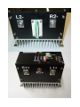
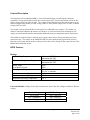
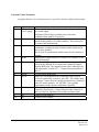
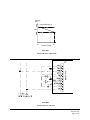
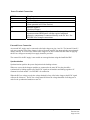
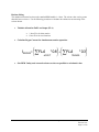
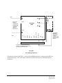
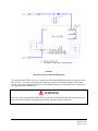
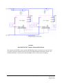
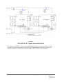
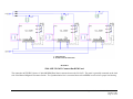
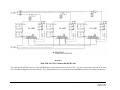
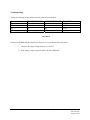
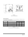
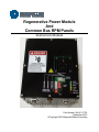
Regenerative Power Module
And
Common Bus RPM Panels
Instruction Manual
Part Number 144-45117-R3
September 2010
©Copyright 2010 Magnetek Material Handling
PRODUCT MANUAL SAFETY INFORMATION
Magnetek, Inc. (Magnetek) offers a broad range of radio remote control products, control products and
adjustable frequency drives, and industrial braking systems for material handling applications. This
manual has been prepared by Magnetek to provide information and recommendations for the installation,
use, operation and service of Magnetek’s material handling products and systems (Magnetek Products).
Anyone who uses, operates, maintains, services, installs or owns Magnetek Products should know,
understand and follow the instructions and safety recommendations in this manual for Magnetek
Products.
The recommendations in this manual do not take precedence over any of the following requirements
relating to cranes, hoists lifting devices or other material handling equipment which use or include
Magnetek Products:
•
•
•
•
•
Instructions, manuals, and safety warnings of the manufacturers of the equipment where the radio
system is used,
Plant safety rules and procedures of the employers and the owners of facilities where the
Magnetek Products are being used,
Regulations issued by the Occupational Health and Safety Administration (OSHA),
Applicable local, state or federal codes, ordinances, standards and requirements, or
Safety standards and practices for the industries in which Magnetek Products are used.
This manual does not include or address the specific instructions and safety warnings of these
manufacturers or any of the other requirements listed above. It is the responsibility of the owners, users
and operators of the Magnetek Products to know, understand and follow all of these requirements. It is
the responsibility of the employer to make its employees aware of all of the above listed requirements and
to make certain that all operators are properly trained. No one should use Magnetek Products prior to
becoming familiar with and being trained in these requirements and the instructions and safety
recommendations in this manual.
WARRANTY INFORMATION
FOR INFORMATION ON MAGNETEK’S PRODUCT WARRANTIES BY PRODUCT TYPE,
PLEASE VISIT WWW.MAGNETEKMH.COM.
Regenerative Power Module - September 2010
144-45117-R3
Page 3 of 20
Disclaimer of Warranty
Magnetek, hereafter referred to as Company, assumes no responsibility for improper programming of a
drive by untrained personnel. A drive should only be programmed by a trained technician who has read
and understands the contents of this manual. Improper programming of a drive can lead to unexpected,
undesirable, or unsafe operation or performance of the drive. This may result in damage to equipment or
personal injury. Company shall not be liable for economic loss, property damage, or other consequential
damages or physical injury sustained by the purchaser or by any third party as a result of such
programming. Company neither assumes nor authorizes any other person to assume for Company any
other liability in connection with the sale or use of this product.
WARNING
Improper settings of this product can lead to unexpected, undesirable, or unsafe operation or
performance of the controls.
Regenerative Power Module - September 2010
144-45117-R3
Page 4 of 20
General Description
The Regenerative Power Module (RPM) is a universal brake chopper circuit designed to dissipate
regenerative energy produced by a motor into a fixed resistor load. The universal module covers the DC
supply voltage range from 200V to 660V. The voltage selector link located on the outside front cover of
the unit configures the module for LOW voltage (200V to 300V), MED voltage (300V to 500V) or HIGH
voltage (500V to 660V).
The module is powered from the DC bus and requires no additional power supplies. The module can
either be connected behind the M contactor of each drive or can be connected to the incoming DC bus
using a separate mounted controller that includes additional protective components and line capacitance.
This module is required whenever the main power supply cannot receive the regenerated power being
return to the line. The voltage on the OmniPulse DDC bus rises rapidly during regeneration (100 ms).
Bus feed rectifier units that do not have a dump circuit or have slow reacting circuits require the use of the
RPM module and dump resistor.
RPM Features
Ratings
Input Voltage Range
Brake Level Adjustment Range
Rated Amps
Peak Brake Current
Duty Cycle (800A peak)
Minimum connected dump resistor
Maximum Operating Temperature
Minimum Operating Temperature
Minimum 200VDC
Maximum 660 VDC
Minimum 256 VDC
Maximum 800 VDC
400A
800A
10% (40° C ambient)
5% (60° C ambient)
1 ohm
60° C
-20° C
Universal Module (Voltage selector link, located on the front of the unit, configures module to DC Bus
voltage)
Link Setting
330 V (Low)
495 V (Medium)
660 V (High)
DC Bus Range
200 – 300 VDC
300 – 500 VDC
500 – 660 VDC
Regenerative Power Module - September 2010
144-45117-R3
Page 5 of 20
Voltage Display
A 10-LED Switch Level bar graph provides a visual display of the approximate bus voltage level
when the brake transistor turns on.
Simplified Switching Level Selection
An 8-position DIP switch provides transistor turn on switching level selection in 15 steps.
Link Setting
330
495
660
Adj Range
256 – 400 VDC
384 - 600
512 - 800
Volt/Step
16
24
32
Choose the appropriate setting for the voltage link set up and set the appropriate corresponding
DIP switch position on. All other DIP settings must be off.
•
Mode Switches
A 4-position DIP switch provides the following configuration selections:
DIP Position
1
2
3
4
Off Setting
Enable Ext Intlk
Auto Reset
2-Term Res
Not Used
On Setting
Disable Ext Intlk
Remote Reset
3-Term Res
Not Used
The External Interlock may be used for the connection of a normally closed temperature switch
mounted at the power resistor.
•
Overheat Protection
The thermistor mounted on the heat sink is used to protect against failure caused by excessive
duty combined with excessive ambient temperatures. The unit is shut down when the heat sink
temperature exceeds 95° C.
•
24V Output for Fan
A +24V Fan output is available for supplemental cooling. The Fan output is capable of
delivering up to 5W for the addition of an external fan separately mounted from the RPM unit.
The output becomes active when the heat sink temperature exceeds 65° C.
Regenerative Power Module - September 2010
144-45117-R3
Page 6 of 20
•
LED Fault and Status Indicators
LED status indicators provide the following indications:
COLOR
MARKING
GREEN POWER
•
GREEN
INTERLOCK
GREEN
READY
AMBER
AMBER
RED
ACTIVE
RESET
OVERTEMP
RED
IGBT FAULT
DESCRIPTION
Indicates that the brake chopper power supply is
present
Indicates that the external contact is closed when the
interlock is enabled or that the interlock is in the
disabled position
Indicates that no fault condition exists and that the
external interlock is not open
Indicates that the brake chopper is conducting
Indicates that the reset circuit is activated
Indicates that the heat sink temperature has reached
95° C and the module has shut down to protect the
transistor.
Indicates that the module is shut down on short
circuit IGBT detection
TEST Switch
The TEST switch simulates a DC bus voltage increase; this input is used to set the turn on voltage
and verify transistor and resistor functionality.
Regenerative Power Module - September 2010
144-45117-R3
Page 7 of 20
External Control Terminals
A pluggable Phoenix screw terminal connector is provided to facilitate additional functionality:
Pin
1
Signal Name
External
+24V Supply
2
Fault
3
Sync
4
Reset
5
Fan
6
7
Ready
Level
8
I-Lock
9
10
0V
0V
Function
Allows control circuit of the brake module to be powered from
an external supply.
(Eliminates 25ms delay for control power to become
established from main DC bus power.)
24 volts between this terminal and terminal 9 or 10 indicates
that the brake module is in a fault condition. This can be used
for remote fault annunciation.
Connect to same terminal of other brake modules to
synchronize switching in order to balance brake load between
two or more modules.
The 0V pins of synchronized modules must also be connected
together.
Apply positive pulse between 10V and 24V to remotely reset a
brake module fault.
The 24-volt DC Fan output is capable of delivering up to 5W of
power for the addition of an external fan separately mounted
from the RPM unit. The output becomes active when the heat
sink temperature exceeds 65° C. Connect between terminals 5
and 10.
24 Volt output, RPM ready
Brake level switching allows the switching voltage turn on
level to be reduced by as much as 100 volts. The voltage input
to terminal 7 can be fixed or variable and needs to be connected
to the 0V circuit common. See FIGURE 1 for a graphic
representation of the dynamic adjustment capability.
Connection point for resistor overheat protection switch.
Normally-closed switch: Connect between either terminals 8
and 9 or 8 and 10. Input has a 50 ms filter to reduce noise.
Control circuit common.
Control circuit common
Regenerative Power Module - September 2010
144-45117-R3
Page 8 of 20
Switching
level
Normal switching level
100V
0V
Terminal 7 Voltage
10V
FIGURE 1
RPM UNIT
Turn On Dynamic Adjustment
FIGURE 2
Syncrhonization Connection
Regenerative Power Module - September 2010
144-45117-R3
Page 9 of 20
Power Terminal Connections
TERM
L1+
L2R1+
R2R3+
Function
DC Bus Positive
DC Bus Negative
Resistor Positive
(Same potential as DC Bus Positive)
Resistor Negative
(Switched Output)
Terminal must be connected to the external resistor whenever the
separate mounted RPM panel with the required additional
protective components is connected directly to the DC bus. See
FIGURE 4 for example connections.
External Power Connection
An external 24V supply may be connected to the brake chopper at pins 1 and 10. The internal 24 and 15
volt power supplies of the brake chopper is derived from the main DC bus input and takes approximately
50ms to start up. If it is necessary for the brake chopper to be active within less than 50ms of applying
the DC bus voltage an external power supply should be provided.
The external 24-volt DC supply is not needed on crane applications using the OmniPulse DDC.
Synchronization
Synchronization equalizes the power dissipation in the braking resistors.
When two or more brake chopper modules are connected to the same DC bus they should be
synchronized by linking together all of the SYNC signals on all modules and linking together a 0V
common from each module. See FIGURE 2 for connection.
When the DC bus voltage exceeds the voltage threshold of any of the brake choppers the SYNC signal
will turn all of them on. The DC bus voltage must fall below the voltage threshold of all choppers in
order for the synchronized modules to turn off.
Regenerative Power Module - September 2010
144-45117-R3
Page 10 of 20
Resistor Sizing
The minimum connected resistor to the standard RPM module is 1 ohm. The resistor value can be greater
than this but never lower. Use the following procedure to calculate the continuous current rating of the
resistor chosen.
1.
Tabulate all motion Full Load Amps (FLA)
•
•
2.
½ hour FLA for hoist motion
1 hour FLA for travel motions
Calculate Regen Current for simultaneous motion operation
⎛
⎞ ⎛
⎞
IREGEN= ⎜∑FLA * 0.8⎟ + ⎜∑FLA
* 0.3⎟
HOIST
TRAVEL
⎝
⎠ ⎝
⎠
3.
Size RPM Unit(s) and external resistors as close as possible to calculated value.
Regenerative Power Module - September 2010
144-45117-R3
Page 11 of 20
L1(+)
R1
L1 (+) for
RPM is
connected
between M
contactor
and the
DDC drive
L1(+)
RPM resistor
R2
144-45087
RPM
*
R3
FAULT
SYNCH
RESET
FAN
READY
BRAKE LEVEL
INTERLOCK
0 VDC
0VDC
L2(-)
+ 24 VDC
L2(-)
1
2
3
4
5
6
7
8
9
10
* EXTERNAL
RESISTOR
GRIDS WITH
NORMALLYCLOSED OVER
TEMPERATURE
SWITCH
IN THIS CONFIGURATION SET DIP
SWITCH - 3 “TERMINAL RESISTOR” TO
OFF POSITION ON RPM UNIT
FIGURE 3
400 AMP Single RPM Unit
The connection shown in FIGURE 3 is a single 400 AMP RPM Unit that is connected to the DDC bus
after the M contactor. This is the simplest connection possible and requires no additional protective
components.
Regenerative Power Module - September 2010
144-45117-R3
Page 12 of 20
FIGURE 4
400 AMP 230-320V Common Bus RPM Panel
The connection in FIGURE 4 shows a separately mounted 400 AMP RPM Panel that is connected across
the 230-320V. The panel is generally connected on the load side of the Manual Magnetic Disconnect
Switch. Connections direct to the DC Bus require additional protective components that are included on
the separately mounted RPM panel.
WARNING
Warning: Connecting the RPM Module directly to the DC Bus without the additional components shown
above can result in damage to the RPM unit and other equipment on the common bus.
Regenerative Power Module - September 2010
144-45117-R3
Page 13 of 20
FIGURE 5
400 AMP 360-720V Separate Mounted
The connection in FIGURE 5 shows a separately mounted 400 AMP RPM Panel that is connected across
the 360-720V. The panel is generally connected on the load side of the Manual Magnetic Disconnect
Switch. Connections direct to the DC Bus require additional protective components that are included on
the separately mounted RPM panel.
Regenerative Power Module - September 2010
144-45117-R3
Page 14 of 20
FIGURE 6
800 AMP 230-320V Separate Mounted RPM Panel
The connection in FIGURE 6 shows an 800 AMP RPM Panel that is connected across the 230-320V.
The panel is generally connected on the load side of the Manual Magnetic Disconnect Switch. The
Synchronization line is connected between both RPMs in order to have proper load sharing.
Regenerative Power Module - September 2010
144-45117-R3
Page 15 of 20
FIGURE 7
800 AMP 360-720V Separate Mounted RPM Panel
The connection in FIGURE 7 shows an 800 AMP RPM Panel that is connected across the 360-720V.
The panel is generally connected on the load side of the Manual Magnetic Disconnect Switch. The
Synchronization line is connected between both RPMs in order to have proper load sharing.
Regenerative Power Module - September 2010
144-45117-R3
Page 16 of 20
FIGURE 8
1200 AMP 230-360V Common Bus RPM Panel
The connection in FIGURE 8 shows a 1200 AMP RPM Panel that is connected across the 230-360V. The panel is generally connected on the load
side of the Manual Magnetic Disconnect Switch. The Synchronization line is connected between both RPMs in order to have proper load sharing.
Regenerative Power Module - September 2010
144-45117-R3
Page 17 of 20
FIGURE 9
1200 AMP 360-720V Common Bus RPM Panel
The connection in FIGURE 9 shows a 1200 AMP RPM Panel that is connected across the 360-720V. The panel is generally connected on the load
side of the Manual Magnetic Disconnect Switch. The Synchronization line is connected between both RPMs in order to have proper load sharing.
Regenerative Power Module - September 2010
144-45117-R3
Page 18 of 20
Troubleshooting
Taking the following measurements can check the transistor and diode.
Q1
POSITIVE PROBE
NEGATIVE PROBE READING
DP
R2
L1
0.312
DN
L2
R2
0.312
QP
L1
R2
> 0.6
QN
R2
L2
> 0.6
TRANSISTOR AND DIODE CHECK USING D.M.M. SET ON DIODE SCALE
FIGURE 10
If the Green POWER indicator light on the front cover is out make the following checks.
1. Check for the supply voltage between L1+ and L22. If the supply voltage is present replace the entire RPM unit.
Regenerative Power Module - September 2010
144-45117-R3
Page 19 of 20
FIGURE 11
Dimensions 400 AMP RPM Unit
Enclosure Dimensions
The following table describes the dimensions for the common bus RPM panels. The NEMA 4 enclosures
have screw latches to secure the hinged door.
Part Number
Description
144-45111
144-45112
144-45113
144-45114
144-45115
144-45116
400 Amp/230~320 VDC RPM Panel
800 Amp/230-320 VDC RPM Panel
1200 Amp/230~320 VDC RPM Panel
400 Amp/360~720 VDC RPM Panel
800 Amp/360~720 VDC RPM Panel
1200 Amp/360~720 VDC RPM Panel
Dimensions (in)
Height
Width
Length
30
24
16
48
36
16
48
36
16
30
24
16
48
36
16
48
36
16
FIGURE 12
Enclosure Dimensions for the Common Bus RPM Panels
Regenerative Power Module - September 2010
144-45117-R3
Page 20 of 20