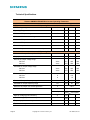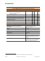
1
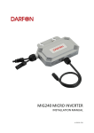
Installation and Operations Manual
Siemens Microinverter
Model SMIINV215R60XX
Contact Information
Siemens Industry, Inc.
Infrastructure & Cities Sector
Low and Medium Voltage
5400 Triangle Parkway
Norcross, GA 30092
1-800-241-4453
www.usa.siemens.com/microsolar
[email protected]
FCC Compliance
This equipment has been tested and found to comply with the limits for a Class B digital device,
pursuant to part 15 of the FCC Rules. These limits are designed to provide reasonable protection
against harmful interference in a residential installation. This equipment generates, uses and can
radiate radio frequency energy and, if not installed and used in accordance with the instructions,
may cause harmful interference to radio communications. However, there is no guarantee that
interference will not occur in a particular installation. If this equipment does cause harmful
interference to radio or television reception, which can be determined by turning the equipment
off and on, the user is encouraged to try to correct the interference by one or more of the
following measures:
•
Reorient or relocate the receiving antenna.
•
Increase the separation between the equipment and the receiver.
•
Connect the equipment into an outlet on a circuit different from that to which the receiver
is connected.
•
Consult the dealer or an experienced radio/TV technician for help.
Changes or modifications not expressly approved by the party responsible for compliance may
void the user’s authority to operate the equipment.
Other Information
Product information is subject to change without notice. All trademarks are recognized as the
property of their respective owners.
For Siemens Microinverter Warranty Terms and Conditions, see the Appendix on page 28 of this
manual.
© 2011 Siemens Industry, Inc. All rights reserved.
Page 2
Copyright 2011 Siemens Industry, Inc.
141-00015, Rev 01
Table of Contents
Important Safety Information ................................................................................ 4
Read this First ....................................................................................................4
Symbol Legend .................................................................................................. 4
Safety Instructions ............................................................................................... 4
The Siemens Microinver System ........................................................................... 4
How the Microinverter Works .................................................................................. 6
System Monitoring............................................................................................ 6
Optimal Reliability ............................................................................................ 6
Ease of Design ................................................................................................ 6
Siemens Microinverter Installation .......................................................................... 7
Compatibility and Capacity ..................................................................................... 7
Parts and Tools Required ...................................................................................... 8
Lightning Surge Suppression .................................................................................. 8
Installation Procedure ........................................................................................... 9
Step 1 – Measure AC at Service Entrance Conductors ................................................... 9
Step 2 – Install the AC Branch Circuit Junction Box ..................................................... 10
Step 3 – Position the Trunk and Drop Cabling ............................................................ 11
Step 4 – Attach the Microinverters to the Racking ....................................................... 12
Step 5 – Dress the Trunk and Drop Cable ................................................................ 13
Step 7 – Terminate the unused end of the Trunk and Drop Cable .................................... 15
Step 8 – Connect the Cable to Junction Box(es) ......................................................... 16
Step 9 – Ground the System ................................................................................ 17
Step 10 – Complete the Installation Map .................................................................. 18
Complete the Siemens Map .............................................................................. 18
Alternative: Create Your Own Map ..................................................................... 18
Step 11 – Connect the PV Modules ........................................................................ 18
Step 12 – Build the Virtual Array ............................................................................ 19
Commissioning and Operation ............................................................................ 20
Commissioning................................................................................................. 20
Operating Instructions ........................................................................................ 20
Troubleshooting ............................................................................................. 21
Status LED Indications and Error Reporting .............................................................. 21
Startup LED Operation: .................................................................................... 21
Ground Fault Detection Indicator (GFDI) Fault: ....................................................... 21
Other Faults: ................................................................................................ 21
Troubleshooting an Inoperable Microinverter ............................................................. 22
Disconnecting a Microinverter from the PV Module ...................................................... 23
Installing a Replacement Microinverter .................................................................... 24
Technical Data ............................................................................................... 25
Technical Considerations .................................................................................... 25
Technical Specifications ...................................................................................... 26
Siemens SMIINV215R60XX Microinverter Operating Parameters ................................. 26
Appendix ...................................................................................................... 28
Limited Warranty............................................................................................... 28
Siemens Installation Map .................................................................................... 30
Sample Wiring Diagram – SMIINV215R60XX, 240 Vac or 208 Vac Single Phase ................. 31
Sample Wiring Diagram – SMIINV215R60XX, 208 Vac ................................................ 32
Page 3
Copyright 2011 Siemens Industry, Inc.
141-00015, Rev 01
Important Safety Information
Read this First
This manual contains important instructions for use during installation and maintenance
of the Siemens SMIINV215R60
SMIINV215R60XX Microinverter.
Symbol Legend
To reduce the risk
sk of electrical shock, and to ensure the safe installation and operation of
the Siemens Microinverter, the following safety symbols appear throughout this document
to indicate dangerous conditions and important safety instructions.
DANGER Hazardous vo
voltage.
ltage. Will cause death or serious injury. Turn off Power before
working on this equipment. This indicates a situation where the present voltage could
cause injury or death. Extreme caution is required when servicing or installing the
equipment referenced.
nced.
WARNING!! This indicates a situation where failure to follow instructions may be a safety
hazard or cause equipment malfunction. Use extreme caution and follow instructions
carefully.
NOTE:: This indicates information particularly important for optimal system operation.
Follow instructions closely.
Safety Instructions
Page 4
Perform all electrical installations in accordance with all local electrical codes and the
R
National Electrical Code (NEC), ANSI/NFPA 70.
Be aware that only qualified personnel sshould install and/or replace Siemens Microinverters.
Do not attempt to repair the Siemens Microinverter; it contains no user-serviceable
serviceable parts. If it
fails, please contact Siemens customer service to obtain an RMA number and start the
replacement process. Tampering with or opening the Siemens Microinverter will void the
warranty.
Before installing or using the Siemens Microinverter, please read all instructions and
cautionary markings in the technical description and on the Siemens Microinverter System
and the Photovoltaic (PV
PV) array.
Connect the Siemens Microinverter to the electrical utility grid only after receiving prior
approval from the utility company.
Be aware that the body of the Siemens Microinverter is the heat sink and can reach a
temperature of 80° C (176
(176° F). To reduce risk of burns, do not touch.
Do NOT disconnect the PV module from the Siemens Microinverter without first removing AC
power. Disconnect AC power by disengaging the circuit breaker or disconnect before the first
inverter connection.
Copyri
Copyright 2011 Siemens Industry, Inc.
141-00015, Rev 01
The Siemens Microinverter System
The Siemens Microinverter System is the world’s most technologically advanced inverter system
for use in utility-interactive applications. This manual details the safe installation and operation of
the Siemens Microinverter.
The three key elements of a Siemens Microinverter System are:
•
the Siemens Microinverter
•
the Envoy™ Communications Gateway
•
the Enlighten™ web-based monitoring and analysis system
This integrated system maximizes energy harvest, increases system reliability, and simplifies
design, installation and management.
Page 5
Copyright 2011 Siemens Industry, Inc.
141-00015, Rev 01
How the Microinverter Works
The Siemens Microinverter maximizes energy production from your photovoltaic (PV) array. Each
Siemens Microinverter is individually connected to one PV module in your array. This unique
configuration means that an individual Maximum Power Point Tracker (MPPT) controls each PV
module. This ensures that the maximum power available from each PV module is exported to the
utility grid regardless of the performance of the other PV modules in the array. That is, although
individual PV modules in the array may be affected by shading, soiling, orientation, or module
mismatch, the Siemens Microinverter insures top performance for its associated PV module. The
result is maximum energy production from your PV system.
System Monitoring
Indoors, you can install the Envoy Communications Gateway by plugging it into any convenient
120Vac wall socket and providing an Ethernet connection to your broadband router or modem.
After installation of the Envoy, the Siemens Microinverters automatically begin reporting to the
Enlighten web server. The Enlighten software presents current and historical system performance
trends, and it informs you when the PV system is not performing as expected.
Optimal Reliability
Microinverter systems are inherently more reliable than traditional inverters. The distributed
nature of a microinverter system ensures that there is no single point of system failure in the PV
system. Siemens Microinverters are designed to operate at full power at ambient temperatures as
high as 65° C (150° F). The inverter housing is designed for outdoor installation and complies
with the NEMA 6 environmental enclosure rating standard:
NEMA 6 rating definition: Indoor or outdoor use primarily to provide a degree of
protection against hose-directed water, and the entry of water during occasional
temporary submersion at a limited depth, and damage from external ice
formation.
Ease of Design
PV systems using Siemens Microinverters are very simple to design and install. You will not need
string calculations, and you can install individual PV modules in any combination of module
quantity, type, age and orientation. You won’t need to install cumbersome centralized or string
inverters. Each microinverter quickly mounts on the PV racking, directly beneath each PV
module. Low voltage DC wires connect from the PV module directly to the co-located
microinverter, eliminating the risk of personnel exposure to dangerous 600 Vdc power.
Page 6
Copyright 2011 Siemens Industry, Inc.
141-00015, Rev 01
Siemens Microinverter Installation
Follow the instructions in this section to install Siemens SMIINV215R60XX Microinverters.
DANGER Hazardous voltage. Will cause death or serious injury. Turn off
Power before working on this equipment. Be aware that installation of this
equipment includes risk of electric shock. Normally grounded conductors may
be ungrounded and energized when a ground fault is indicated.
WARNING: Before installing the Siemens Microinverter, read all instructions
and cautionary markings in the user manual, on the Siemens Microinverter, and
on the photovoltaic array.
WARNING: Perform all electrical installations in accordance with all local
R
electrical codes and the NEC , ANSI/NFPA 70.
WARNING: Connect the Siemens Microinverter to the electrical utility grid only
after receiving prior approval from the utility company.
WARNING: Be aware that only qualified personnel should connect the Siemens
Microinverter to the electrical utility grid.
Compatibility and Capacity
The Siemens SMIINV215R60XX Microinverters are electrically compatible with most 60-cell PV
modules. For more information, see Technical Data page 25 of this manual.
Refer to the Siemens website (http://www.usa.siemens.com/microsolar) for a list of electricallycompatible PV modules and approved PV module racking systems. To ensure mechanical
compatibility, be sure to order the correct connector type for both microinverter and PV module
from your distributor.
Electrical Compatibility
Model Number
Works with PV Module Type
Module Connector Type
SMIINV215R60MC
60 cell
MC-4 Type 2 Locking or
Amphenol H4 Locking
SMIINV215R60TY
60 cell
Tyco Solarlock Locking
Voltage and Capacity
Maximum number of SMIINV215R60XXs per 20 amp AC Branch Circuit
Service type
Max SMIINV215R60XXs
Max PV modules per branch
per branch
Page 7
Single phase 240 V or 208 V
17
17
Three phase 208 V
25
25
Copyright 2011 Siemens Industry, Inc.
141-00015, Rev 01
Parts and Tools Required
In addition to the SMIINV215R60XX microinverters, PV modules, racking, and associated
ass
hardware, you will need the following items.
Siemens equipment:
• Trunk and Drop cabling, as needed
•
•
•
•
•
NOTE: Order the correct Trunk and Drop Cable type. Installers must order cable for
either split phase 240 VAC, typical for residential applications
applications,, or three phase 208
VAC, typical for commercial installations. All drop connectors on the Trunk and Drop
Cable bear labels indicating the cable voltage designation. Use split phase 240 VAC
cable at sites with 208 single phase service.
Grounding clips
Drop connector seals, as needed (for any unused drops on Trunk and Drop Cabling)
Cabling
Terminator caps, as needed (for unused ends of Trunk and Drop Cabling)
Cabling
Trunk and Drop disconnect tool (a number 3 Phillips screwdriver can be substituted)
Other items:
unction box
• Appropriate junction
• Continuous grounding conductor, grounding washers
• Number 2 Phillips screwdriver
• Torque wrench, sockets, wrenches for mounting hardware
• Adjustable wrench or open
open-ended wrench (for terminator caps)
• Tool for PV module locking connectors
• Mechanics
cs mirror (for viewing indicator lights on the undersides of the microinverters)
Lightning Surge Suppression
Lightning does not actually need to strike the equipment or building where the PV system is
installed to cause damage. Often, a strike nearby wil
willl induce voltage spikes in the electrical grid
that can damage equipment. Siemens Microinverters have integral surge protection, greater than
most traditional inverters. However, if the surge has sufficient energy, the protection built into the
Microinverter
er can be exceeded, and the equipment can be damaged.
As the Siemens Limited Warranty does not cover “acts of God” such as lightning strikes, and
since lightning strikes can occur anywhere, it is best practice to install surge protection as part of
any solar
lar installation. We recommend the following protection devices. These have been tested
to ensure that they do not interfere with power line communications. Install per vendor
instructions.
Vendor: Siemens, Part Number
Number: TPS3 03
Application:: Residential 12
120/240V Split Phase where a Neutral to Ground (N-G
G) bond exists.
Vendor: Siemens, Part Number
Number: TPS3 12
Application: Commercial branch panel protection
(See the vendor datasheet for th
these models at http://www.usa.siemens.com/tvss
usa.siemens.com/tvss ).
Page 8
Copyri
Copyright 2011 Siemens Industry, Inc.
141-00015, Rev 01
Installation Procedure
Installing the Siemens Microinverter System involves several key steps. Each step listed below is
detailed in the following pages.
Step 1 – Measure V
VAC at Service Entrance Conductors
Step 2 – Install the AC Junction Box
Step 3 – Position the Trunk and Drop Cabling
Step 4 – Attach the Microinverters to the Racking
Step 5 – Dress the Trunk and Drop Cable
Step 6 – Connect the Microinverters
Step 7 – Terminate the unused end of the Trunk and Drop Cable
Step 8 – Connect the Cable to AC Junction Box(es)
Step 9 – Ground the System
Step 10 – Complete the Paper Map
Step 11 – Connect the PV Modules
Step 12 – Build the Virtual Array
DANGER Hazardous voltage. Will cause death or serious injury. Turn off Power before
be
working on this equipment. DO NOT connect Siemens Microinverters to the utility grid
until you have completed all of the installation procedures as described in the following
sections.
Step 1 – Measure AC at Service Entrance
Conductors
Measure AC line voltage at the service entrance conductors
to confirm AC service at the site. Acceptable ranges are
shown in the following table.
120/240 VAC
AC or 208Y/120 V
VAC Single Phase
Page 9
208Y/120 VAC Three Phase
L1 to L2
211 to 264 Vac
L1 to L2 to L3
183 to 229 Vac
L1, L2 to neutral
106 to 132 Vac
L1, L2, L3 to neutral
106 to 132 Vac
Copyri
Copyright 2011 Siemens Industry, Inc.
141-00015, Rev 01
Step 2 – Install the AC Branch Circuit Junction Box
DANGER Hazardous voltage. Will cause death or serious injury. Turn off Power before
working on this equipment. Do NOT exceed
xceed the maximum number of microinverters in
an AC branch circuit as listed on page 27 of this manual. You must protect each
microinverter AC branch cir
circuit with a 20 A maximum breaker.
DANGER Hazardous voltage. Will cause death or serious injury. Turn off Power before
working on this equipment. Size the AC wire gauge to account for voltage drop. All
components of system wiring must be considered, including internal voltage drop within the
length of Trunk and Drop cabling.
WARNING! Only use electrical system components approved for wet locations.
a. Size the AC wire gauge to account for voltage drop. Select the correct wire size
based on the dist
distance
ance from the beginning of the microinverter AC branch circuit to
the breaker in the load center.
All components of system wiring must be considered, including internal voltage drop
within the length of Trunk and Drop Cable. Typically, three wire sections and several
wire terminations must be quantified. There is also some resistance associated with
each circuit breaker. As all of these resistances are in series, they add together.
Since the same current is flowing through each resistance, the total voltage drop is
total current times the total resistance. For a single
single-phase
phase system, the total
resistance is equal to two times the one
one-way
way resistance. For a three-phase
three
system,
each of the three line currents and resistances must be calculated.
Use the voltage drop charts at: http://www.usa.siemens.com/microsolar
usa.siemens.com/microsolar to select the
®1
correct wire size. NEC guidelines for voltage drop on feeder and branch circuit
conductors will not be adequate for microinverter bran
branch
ch circuits that contain the
maximum allowable microinverters.
b. Install an appropriate junction
box at a suitable location on the
PV racking system
system. You can
center feed the branch, or you
can install the junction box at
the end of a row of PV modules.
c. Provide
ide an AC connection from
the junction box back to the
utility interconnection using
equipment and practices as
R
required by the NEC and local
jurisdictions.
1
National Electrical Code is Registered Trademark of the National Fire Protection Association
Page 10
Copyri
Copyright 2011 Siemens Industry, Inc.
141-00015, Rev 01
Step 3 – Position the Trunk and Drop Cabling
The cabling is a continuous length of 12 AWG, ou
outdoor
tdoor rated cable with a connector for each
microinverter placed each PV module width. The microinverters plug directly into the cable, and
the cable is terminated into the junction box that feeds electricity back to the system AC
disconnect.
WARNING! Make sure you using the correct cable type. Installers must order Trunk and
Drop Cable for either 240 VAC single phase, typical for residential applications, or 208
VAC three phase, typical for commercial installations. All drop connectors on the cable
bearr labels indicating the cable type. Installers can use 240 VAC cable at sites with 208
single phase service.
a. Lay the Trunk and Drop cabling along the route it will travel, positioning the
connectors so that they align with the PV modules.
odules have a central stiffening brace. In these cases, do not position the
NOTE: Many modules
connector and microinverter at the exact center of the PV module. Instead position the drop
connectors so that the connectors do not conflict with the braces
b. Module widths vary by manufacturer. The connector cable spacing is designed for
the widest PV modules compatible with Siemens Microinverters. If narrower modules
are used, it may be necessary to account for excess cable by adding a ‘loop’ of cable
at suitable intervals.
Page 11
Copyri
Copyright 2011 Siemens Industry, Inc.
141-00015, Rev 01
Step 4 – Attach the Microinverters to the Racking
a. Mark the approximate centers of each PV module on the racking system.
b. Evaluate the location of the microinverter
with respect to the PV module junction
box or any other obstructions.
c. Ensure both that the micr
microinverter does
not interfere with the PV module frames
or stiffening brace, and that the drop
cable from the microinverter can easily
reach the connector on the Trunk and
Drop cable.
DANGER Hazardous voltage. Will cause death or serious injury. Turn off Power before
working on this equipment. Do NOT exceed the maximum number of microinverters in
an AC branch circuit as listed on page 27 of this manual.
ual. You must protect each
microinverter AC branch circuit with a 20A maximum breaker.
WARNING:: Allow a minimum of 1.9 cm (0.75 inches) between the roof and the bottom of
the microinverter. Also allow 1.3 cm (0.50 inches) between the back of the PV module
modul
and the top of the inverter. Do not mount the microinverter in a location that allows longlong
term exposure to direct sunlight (i.e., it should be covered by the PV module).
d. Ground the microinverters using either a continuous, unbroken grounding conductor
or approved grounding washers. If using grounding washers (e.g., WEEB) to ground
the microinverter chassis to the PV module racking, choose a grounding washer that
is approved for the racking manufacturer. Install one grounding washer per
microinverter. To
Torque
rque the microinverter fasteners to the values below.
• 1/4” mounting hardware – 45 lb-in minimum
• 5/16” mounting hardware – 80 lb-in minimum
NOTE:: Using a power screwdriver is not recommended due to risk of galling.
Compatible grounding washer part numbers are included in the Racking Compatibility
Application Note. Installation guidelines are included in the Grounding Washer
Application Note. Refer to both documents at:
http://www.usa.siemens.com/microsolar
e. With the silver side of the microinverter facing up and the black side facing down,
mount one microinverter at each of these locations using suitable hardware. The
indicator light on the underside of the microinverter will be facing the roof.
Page 12
Copyri
Copyright 2011 Siemens Industry, Inc.
141-00015, Rev 01
Step 5 – Dress the Trunk and Drop Cable
a. Attach the Trunk and Drop cabling to the rack using the recommended clips, or you
may use tie wraps. The cable clips are designed so that the drop cable from the
microinverter can also be dressed into the clip underneath the Trunk and Drop cable.
NOTE:: There are two through
through-holes
holes in the trunk connector. These are not for
mounting, but are used to disconnect the connector. Keep these release holes
clear and accessible.
b. Dress any excess cabling in loops so that it does not contact the roof. Do not leave
the cabling to rest on the roof. There are several ways to support the cable. One
method is to place tie wraps or clips on either side of the Trunk and Drop Connector.
Use one or two additional clips, tie wraps, or other support scheme to secure the
cable between connectors.
Page 13
Copyri
Copyright 2011 Siemens Industry, Inc.
141-00015, Rev 01
Step 6 – Connect the Microinverters
a. Remove the temporary shipping cap from the
Trunk and Drop Cable and connect the inverter.
There are two latching mechanisms within the
connectors. Listen for two clicks as the
connectors engage. Ensure that both latching
mechanisms have engaged.
b. Repeat for all microinverters in the branch.
c. Cover any unused connector with a sealing cap.
Listen for two clicks as the connectors engage.
Ensure that both latching mechanisms have
engaged.
Do not use the shipping cap to cover unused
connectors. The shipping cap does not provide
an adequate environmental seal. IP67
IP67-rated
sealing caps are required for the system to be UL
compliant and to protect against moisture
ingress.
NOTE:: Within the term “IP67”, “IP” indicates an
Ingress Protection (IP) rating against dust and
liquids. This specific rating of IP67 indicates that this
connector protects against all dust particles and
immersion in liquid.
DANGER Hazardous vvoltage. Will cause death or serious injury. Turn off Power before
working on this equipment. Make sure protective IP67 sealing caps have been installed
on all unused AC connectors. Unused AC connectors are live when the system is
energized by the utility system.
NOTE:: If you need to remove an IP67 sealing cap.
You must use the Siemens disconnect tool or a #3
Phillips screwdriver. Sealing caps may not be reused.
Page 14
Copyri
Copyright 2011 Siemens Industry, Inc.
141-00015, Rev 01
Step 7 – Terminate the unused end of the Trunk and Drop Cable
You must terminate the far end of the Trunk and Drop cable.
a. Remove 60mm (2.5 inches) of the outer jacket of the cable end.
b. Take the screw-on gland portion of the cable terminator and run the cable end
through it.
c. Take the wire holder and run the cable end through it.
d. Bend the individual wires back into the recesses
in the wire holder so that they angle back toward
the cable.
e. Cut the individual wires so that no excess
extends outside of the wire holder. The portion
that angles back will need to extend enough to
fit neatly into the 0.5 cm (0.2 in) slot in the wire
holder and flush with the edge of the cap.
f.
Insert the wire holder into the cap, and screw
the gland portion onto the cap. Ensure that the gland portion is rotating, not the
cap.
g. Hold the cap with an Siemens disconnect tool, or insert a #2 Phillips screwdriver.
Hold the gland portion with a 24 mm (7/8”) wrench. Tighten the gland portion until the
ratcheting feature on the cap bottoms out.
h. Attach the terminated cable end to the racking using a clip or tie wraps so that the
Trunk and Drop Cable and terminator do not touch the roof.
i.
Page 15
Ensure that all cabling is located underneath the PV module.
Copyright 2011 Siemens Industry, Inc.
141-00015, Rev 01
Step 8 – Connect the Cable to Junction Box(es)
a. Connect Trunk and Drop cable into the AC junction box using an appropriate gland or
strain relief fitting. The trunk and drop cable requires a strain relief connector with an
opening of 1.3 cm (0.5 inches) in
diameter.
b. Connect the TRUNK AND DROP cable
into additional junction boxes as
needed to transition to conduit between
smaller sub-arrays.
rrays.
Refer to the wiring diagrams located in
the Appendix of this manual for more
information.
NOTE: Wires are identified as follows: L1 is sheathed in Black, L2 is sheathed in red, L3
is sheathed in blue, Neutral is sheathed in white, and Ground is sheathed in green. The
grounding wire is used to ground the microinverters. A WEEB or continuous ground is
required in addition to this green grounding wire.
120/240 or 208Y/120 VAC
SINGLE PHASE WIRING
208Y
208Y/120 VAC
THREE PHASE WIRING
Balanced 208 VAC three phase is accomplished by alternating phases
es between
microinverters as shown:
NOTE:: The green wire acts as equipment ground. A continuous Grounding Electrode
Conductor (GEC) for system ground is also required as described in the next step.
Page 16
Copyri
Copyright 2011 Siemens Industry, Inc.
141-00015, Rev 01
Step 9 – Ground the System
If you are not using WEEB
B grounding washers to ground the microinverter chassis as described
in step 4, follow the step below. Each Siemens Microinverter comes with a ground clip that can
accommodate a 6-8
8 AWG conductor.
NOTE:: The AC output neutral is not bonded to ground inside the microinverter.
a. Route a continuous GEC through each of the microinverters to the NEC
AC grounding electrode.
®2
-approved
b. You can ground the racking and module to this conductor using a crimp
connection. An alternative method is to connect the micro
microinverter
to the grounded racking using a grounding washer approved
for the racking.
c. Torque the microinverter fasteners to the
values below.
•
•
1/4” mounting hardware – 45 lb-in minimum
5/16” mounting hardware – 80 lb-in minimum
NOTE:: Using a power screwdr
screwdriver
iver is not recommended due to risk of galling.
2
National Electrical Code is Registered Trademark of the National Fire Protection Association
Page 17
Copyri
Copyright 2011 Siemens Industry, Inc.
141-00015, Rev 01
Step 10 – Complete the Installation Map
The Siemens Installation Map is a diagrammatic representation of the physical location of each
microinverter in your PV installation. The virtual array in Enlighte
Enlighten
n is created from the map you
create. Use the blank map in the Appendix to record microinverter placement for the system, or
provide your own layout if a larger or more intricate installation map is required.
Complete the Siemens Map
a. Each Siemens Microinverter
rter has a removable serial number label located on the
mounting plate. Peel the removable serial number label from each Siemens
Microinverter and affix it to the respective location on the Siemens installation map
(see map in the Appendix
Appendix). You can also download
ownload installation maps and examples
from www.usa.siemens.com/microsolar
usa.siemens.com/microsolar.. Remember to keep a copy of the installation
map for your records.
Alternative: Create Your O
Own Map
a. Draw a top-down
down view of the array using the Array Map template (using either the
grid on Side A or the freeform area on Side B). Make sure to leave enough room to
place the serial number stickers.
b. When installing the microinverters, remove the serial number labels located next to
the DC input cables and place them in the correct order on your drawing of the
system. Remember to keep a copy of the installation map for your records.
Step 11 – Connect the PV Modules
NOTE:: Completely install all microinverters and
all system inter-wiri
wiring connections prior to
installing the PV modules.
a. Mount the PV modules above the
microinverters. Each microinverter comes
with two sets of oppositely sexed multi
multicontact connectors.
b. Mate the microinverters and PV modules
as required. Repeat for all rema
remaining PV
modules using one microinverter for each
module.
WARNING: The M215 should be paired only
with a 60-cell
cell PV module.
Page 18
Copyri
Copyright 2011 Siemens Industry, Inc.
141-00015, Rev 01
Step 12 – Build the Virtual Array
When the system is energized and all microinverters are detected by the Envoy Communications
Communication
Gateway, you can create the virtual array in Enlighten from the Siemens map you created. Once
the virtual array is built, Enlighten displays a graphic representation of the PV system. It also
shows detailed current and historical performance information. Please go to
http://enlighten.enphase.com for more information on the Enlighten web-based
based monitoring and
analysis.
a. Scan the paper installation map and upload it to the Activation form online.
b. Use Array Builder to create the virtual array in Enlighten. Use the Installation
nstallation map
created in step 10 as your reference.
NOTE: Go to http://enphase.com/support/videos/ to view an Array Builder demo.
c. If you do not alread
already have an account, please go to http://enlighten.enphase.com and
click “Enlighten Login” to register.
Page 19
Copyri
Copyright 2011 Siemens Industry, Inc.
141-00015, Rev 01
Commissioning and Operation
WARNING: Be aware that only qualified personnel must connect the Siemens
Microinverter
roinverter to the electrical utility grid.
WARNING: Ensure that all AC and DC wiring is correct. Ensure that none of the AC and
DC wires are pinched or damaged. Ensure that all junction boxes are properly closed.
WARNING: Connect the Siemens Microinverter
er to the electrical utility grid only after
receiving prior approval from the utility company.
NOTE: The Status LED of each microinverter will blink green six times to indicate normal
start-up
up operation one minute after DC power is applied.
Commissioning
To commission the Siemens Microinverter PV system:
1. Turn ON the AC disconnect or circuit breaker on each microinverter AC branch
circuit.
2. Turn ON the main utility
utility-grid AC circuit breaker (if applicable). Your system will start
producing power after a five-minute wait time.
3. The Siemens Microinverters will begin sending performance data over the power
lines to the Envoy. The time required for all microinverters to report to the Envoy will
vary with the number of microinverters in the system. The first units should
s
be
detected within 15 minutes but the entire system could take hours to detect.
4. The SMIINV215R60
SMIINV215R60XX
XX has field adjustable voltage and frequency trip points. If
adjustments are required by your local utility, the installer can use the Envoy to
Manage the
he Grid Profile after all microinverters have been detected.
For more information on Envoy operation, refer to the Envoy Installation and Operation Manual at
http://www.usa.siemens.com/microsolar
usa.siemens.com/microsolar.
Operating
ting Instructions
The Siemens Microinverter is powered on when sufficient DC voltage from the module is applied.
One minute after DC voltage is applied, the status LED blinks green six times indicating proper
start–up.
up. You may need to use a mechanics mirro
mirrorr to view indicator lights on the undersides of
the microinverters.
Page 20
Copyri
Copyright 2011 Siemens Industry, Inc.
141-00015, Rev 01
Troubleshooting
Adhere to all the safety measures described throughout this manual. Qualified personnel can use
the following troubleshooting steps if the PV system does not operate correctly.
WARNING: Do not attempt to repair the Siemens Microinverter; it contains no userserviceable parts. If it fails, please contact Siemens customer service to obtain an RMA
number and start the replacement process.
Status LED Indications and Error Reporting
Startup LED Operation:
One minute after DC power is first applied to the microinverter, six short green blinks
indicate a successful microinverter startup sequence.
Six short red blinks after DC power is first applied to the microinverter indicate a failure
during microinverter startup.
Post-Startup LED Indications:
Use a mechanics mirror to view indicator lights on the undersides of the microinverters:
Flashing Green – Producing power and communicating with Envoy
Flashing Orange – Producing power and not communicating with Envoy
Flashing Red – Not producing power
Solid Red – GFDI Fault
Ground Fault Detection Indicator (GFDI) Fault:
A solid red status LED when DC power has been cycled indicates the microinverter has
detected a ground fault error. The LED will remain red and the fault will continue to be
reported by the Envoy until the error has been cleared.
The condition should clear with operator intervention unless conditions causing the event
have not been remedied or if the failure is permanent.
Follow the instructions in the Envoy Communications Gateway Installation and Operation
Manual to clear this condition. Or, for assistance, contact Siemens customer support at 1800-241-4453 or at [email protected].
Other Faults:
All other faults are reported to the Envoy. Refer to the Envoy Installation and Operation
Manual for troubleshooting procedures.
Page 21
Copyright 2011 Siemens Industry, Inc.
141-00015, Rev 01
Troubleshooting an Inoperable Microinverter
WARNING: Be aware that only qualified personnel should troubleshoot the PV array or
the Siemens Microinverter.
DANGER Hazardous voltage. Will cause death or serious injury. Turn off Power before
working on this equipment. Always disconnect AC power before disconnecting the PV
module wires from the Siemens Microinverter.
DANGER Hazardous voltage. Will cause death or serious injury. Turn off Power before
working on this equipment. Never disconnect the DC wire connectors under load. Ensure
that no current is flowing in the DC wires prior to disconnecting. An opaque covering may
be used to cover the module prior to disconnecting the module.
WARNING: The Siemens Microinverters are powered by DC power from the PV
modules. Make sure you disconnect the DC connections and reconnect DC power to
watch for the six short LED blinks one minute after DC is applied.
To troubleshoot an inoperable microinverter, follow the steps in the order shown:
1. Check the connection to the utility grid and verify the utility voltage and frequency are
within allowable ranges shown in the Technical Data section on page 25 of this
manual.
2. Verify that AC line voltage at the service entrance conductors and at the junction box
for each Siemens branch are within the ranges are shown in the following table:
120/240 VAC or 208Y/120 VAC Single Phase
208Y/120 VAC Three Phase
L1 to L2
211 to 264 Vac
L1 to L2 to L3
183 to 229 Vac
L1 to neutral
L2 to neutral
106 to 132 Vac
L1 to neutral
L2 to neutral
L3 to neutral
106 to 132 Vac
3. Verify utility power is present at the inverter in question by removing AC, then DC
power. Never disconnect the DC wires while the microinverter is producing
power. Re-connect the DC module connectors. After one minute, watch for six short
LED blinks.
4. Check the AC branch circuit interconnection harness between all the microinverters.
Verify that each inverter is energized by the utility grid as described in the previous
step.
5. Make sure that any upstream AC disconnects, as well as the dedicated circuitbreakers for each microinverter branch circuit, are functioning properly and are
closed.
6. Verify the PV module DC voltage is within the allowable range shown in the
Technical Data section on page 25 of this manual.
7. Check the DC connections between the microinverter and the PV module.
8. If the problem persists, please call Siemens customer support at 1-800-241-4453 or
at [email protected].
Page 22
Copyright 2011 Siemens Industry, Inc.
141-00015, Rev 01
Disconnecting a Microinverter from the PV Module
To ensure the microinverter is not disconnected from the PV modules under load, adhere to the
following disconnection steps in the order shown:
1. Disconnect the AC by opening the branch circuit breaker.
DANGER Hazardous voltage. Will cause death or serious injury. Turn off Power before
working on this equipment. Disconnect the Siemens Microinverter from the electrical
utility grid prior to servicing.
2. Disconnect the first AC connector in the branch circuit.
The Siemens Microinverter AC connectors are tool-removable only. To disconnect a
microinverter from the Trunk and Drop Cable, insert the two large prongs of the
disconnect tool (shown below) into the two holes in the drop connector. Rock the
connector back and forth while pulling gently to disengage.
If the disconnect tool is not available, insert a #3 Phillips screwdriver into one hole,
and rock that side of the drop connector out. Then, insert the screwdriver into the
other hole and pull the connector out entirely.
3. Cover the module with an opaque cover.
4. Using a DC current probe, verify there is no current flowing in the DC wires between
the PV module and the microinverter.
5. Care should be taken when measuring DC currents due to the fact that most clampon meters must be zeroed first and tend to drift with time.
6. Disconnect the PV module DC wire connectors from the microinverter.
7. Remove the microinverter from the PV array racking.
DANGER Hazardous voltage. Will cause death or serious injury. Turn off Power before working on this
equipment. Do not leave the drop connector uncovered for an extended period. If you do not plan to
replace the microinverter immediately, you must cover any unused connector with a sealing cap. Listen
for two clicks as the connectors engage. Ensure that both latching mechanisms have engaged. Note that
the shipping cap does not provide an adequate environmental seal. IP67-rated sealing caps are required
for the system to be UL compliant and to protect against moisture ingress.
Page 23
Copyright 2011 Siemens Industry, Inc.
141-00015, Rev 01
Installing a Replacement Microinverter
1. With the silver side of the microinverter facing up and the black side facing down,
attach the replacement microinverter to the PV module racking using hardware
recommended by your module racking vendor.
2. If you are using grounding washers (e.g., WEEB) to ground the chassis of the
microinverter, the old grounding washer should be discarded, and a new grounding
washer must be used w
when
hen installing the replacement microinverter. Torque the
microinverter fasteners to the values below.
• 1/4” mounting hardware – 45 lb-in minimum
• 5/16” mounting hardware – 80 lb-in minimum
NOTE:: Using a power screwdriver is not recommended due to risk of galling.
ga
3. If you are using a grounding electrode conductor to ground the microinverter chassis,
attach the grounding electrode conductor to the microinverter ground clamp.
4. Remove the sealing cap from the Trunk and Drop Cable and connect the inverter.
There are
e two latching mechanisms within the connectors. Listen for two clicks as
the connectors engage. Ensure that both latching mechanisms have engaged.
5. Mount the PV module above the microinverter. Each microinverter comes with two
sets of oppositely sexed mul
multi-contact connectors.
6. Mate the microinverters and PV modules as required. Repeat for all remaining PV
modules using one microinverter for each module.
7. Energize the branch circuit breaker, and verify operation of the replacement
microinverter by checking tthe
he indicator light on the underside of the microinverter.
You may need a mechanics mirror to see the indicator light.
8. Initiate a device scan at the Envoy. To do this, press and hold the Menu button on
Envoy for two seconds to bring up the Envoy menu on the LCD window. When the
LCD window displays “Enable Communication Check”, release the Menu button.
9. Use Enlighten’ss Array Builder function to add the newly detected microinverter to the
virtual array.
Page 24
Copyri
Copyright 2011 Siemens Industry, Inc.
141-00015, Rev 01
Technical Data
Technical Considerations
The Siemens SMIINV215R60XX Microinverters are designed to operate with most 60-cell PV
modules. Be sure to verify the voltage and current specifications of your PV module match those
of the microinverter. For more information, refer to the Siemens website
(http://www.usa.siemens.com/microsolar) for a list of compatible PV module racking systems and
PV modules.
WARNING: You must match the DC operating voltage range of the PV module with the
allowable input voltage range of the Siemens Microinverter.
WARNING: The maximum open circuit voltage of the PV module must not exceed the
specified maximum input voltage of the Siemens Microinverter.
The output voltage and current of the PV module depends on the quantity, size and temperature
of the PV cells, as well as the solar insolation on each cell. The highest PV module output voltage
occurs when the temperature of the cells is the lowest and the module is at open circuit (not
operating). The maximum short circuit current rating of the module must be equal to or less than
the maximum input DC short circuit current rating of the microinverter.
A list of compatible PV modules is maintained on the Siemens website
(http://www.usa.siemens.com/microsolar).
Page 25
Copyright 2011 Siemens Industry, Inc.
141-00015, Rev 01
Technical Specifications
Siemens SMIINV215R60XX Microinverter Operating Parameters
Topic
Unit
Min
Typical
Max
MPPT voltage range
V
22
29
36
Operating Range
V
16
Maximum DC input voltage
V
Minimum / Maximum start voltage
V
Maximum DC input short circuit current
A
15
Maximum DC input current
A
10.5
mA
1000
A
0
DC Operating Parameters
Ground fault protection
Maximum input source backfeed current to input source
36
45
22
45
AC Operating Parameters
Maximum AC output Power (-40 to 65 °C)
W
Output power factor
215
0.95
0.99
1
Nominal AC output voltage range
240 Vac
208 Vac
Vrms
Vrms
211
183
240
208
264
229
Extended AC output voltage range
240 Vac
208 Vac
Vrms
Vrms
206
179
240
208
269
232
Maximum AC output current
240 Vac
208 Vac
A
A
Nominal AC output frequency range
Hz
59.3
60
60.5
Extended AC output frequency range
Hz
59.2
60
60.6
Maximum AC output over current protection
A
20 A
Maximum AC output fault current & duration
Apeak, ms
25.2 Apeak over 1.74 ms
ARMS, Cycles
1.05 ARMS over 3 cycles
1.04 ARMS over 5 cycles
0.9
1.0
High AC Voltage trip limit accuracy
%
±2.5
Low AC Voltage Trip limit accuracy
%
±4.0
Frequency trip limit accuracy
Hz
±0.1
Trip time accuracy
ms
±33
Page 26
Copyright 2011 Siemens Industry, Inc.
141-00015, Rev 01
Siemens SMIINV215R60XX Microinverter Operating Parameters
Topic
Unit
Miscellaneous Operating Parameters
Min
Inverters per 20 amp AC branch circuit
240 Vac or 208 Vac Single Phase
208 Vac Three phase
Typical
1
1
Max
17
25
Peak inverter efficiency
%
96.3
CEC weighted efficiency
%
96.0
Static MPP tracking efficiency (weighted EN 50530)
%
99.6
Total Harmonic Distortion
%
Ambient temperature range
°C
Night Tare Loss
3.0
-40
65
mW
Storage temperature range
°C
5
46
-40
65
Features
3
Dimensions not including mounting bracket
(approximate)
17.3 cm x 16.4 cm x 2.5 cm
(6.8” x 6.45” x 1.0”)
Weight
3.5 Lbs
Enclosure environmental rating
NEMA 6
Cooling
Convective – no fan
Communication
Power line
Standard warranty term
25 years, limited
Applicable Standards
UL1741, IEEE1547, FCC Part 15 Class B,
CAN/CSA-C22.2 NO. 0-M91, 0.4-04, and
107.1-01
Integrated AC disconnect
The AC connector has been evaluated
and approved for use as the load-break
®3
disconnect required by the NEC .
National Electrical Code is Registered Trademark of the National Fire Protection Association
Page 27
Copyright 2011 Siemens Industry, Inc.
141-00015, Rev 01
Appendix
Limited Warranty
Siemens Industry Inc. ("Siemens") has developed a highly reliable Microinverter that is designed to
withstand normal operating conditions when used for its originally intended purpose in compliance with
the Siemens User Manual supplied with the originally shipped system. The Siemens limited warranty
(“Limited Warranty”) covers defects in workmanship and materials of the Siemens Microinverter
(“Defective Product”) for a period of twenty-five (25) years from the date of original purchase of such
Microinverter at point of sale to the originally-installed end user location (the "Warranty Period").
During the Warranty Period, the warranty is transferable to a different owner as long as the
Microinverter remains installed at the originally-installed end user location.
During the Warranty Period, Siemens will, at its option, repair or replace the Defective Product free of
charge, provided that Siemens through inspection establishes the existence of a defect that is covered
by the Limited Warranty. Siemens will, at its option, use new and/or reconditioned parts in repairing or
replacing the Defective Product. Siemens reserves the right to use parts or products of original or
improved design in the repair or replacement of Defective Product. If Siemens repairs or replaces a
Defective Product, the Limited Warranty continues on the repaired or replacement product for the
remainder of the original Warranty Period or ninety (90) days from the date of Siemens’s return
shipment of the repaired or replacement product, whichever is later.
The Limited Warranty covers both parts and labor necessary to repair the Defective Product, but does
not include labor costs related to un-installing the Defective Product or re-installing the repaired or
replacement product. The Limited Warranty also covers the costs of shipping repaired or replacement
product from Siemens, via a non-expedited freight carrier selected by Siemens, to locations within the
United States (including Alaska and Hawaii) and Canada, but not to other locations outside the United
States or Canada. The Limited Warranty does not cover, and Siemens will not be responsible for,
shipping damage or damage caused by mishandling by the freight carrier and any such damage is the
responsibility of the freight carrier.
To obtain repair or replacement service under this Limited Warranty, the customer must comply with
the following policy and procedure:
All Defective Product must be returned with a Return Merchandise Authorization Number (RMA)
which customer must request from Siemens. Before requesting the RMA, however, the customer
should contact a Siemens technical support (1-800-241-4453) representative to evaluate and
troubleshoot the problem while the Siemens Microinverter is in the field, since many problems can
be solved in the field.
Page 28
If in-field troubleshooting does not solve the problem, Customer may request the RMA number,
which request must include the following information:
-
Proof-of-purchase of the Defective Product in the form of (1) the dated purchase receipt
from the original purchase of the product at point of sale to the end user, or (2) the dated
dealer invoice or purchase receipt showing original equipment manufacturer (OEM)
status, or (3) the dated invoice or purchase receipt showing the product exchanged under
warranty.
-
Model number of the Defective Product
-
Serial number of the Defective Product
-
Detailed description of the defect
-
Shipping address for return of the repaired or replacement product
All Defective Product authorized for return must be returned in the original shipping container or
other packaging that is equally protective of the product
Copyright 2011 Siemens Industry, Inc.
141-00015, Rev 01
The returned Defective Product must not have been disassembled or modified without the prior
written authorization of Siemens
Siemens Microinverters are designed to withstand normal operating conditions and typical wear and
tear when used for their original intent and in compliance with the installation and operating
instructions supplied with the original equipment. The Limited Warranty does not apply to, and
Siemens will not be responsible for, any defect in or damage to any Siemens Microinverter: (1) that
has been misused, neglected, tampered with, altered, or otherwise damaged, either internally or
externally; (2) that has been improperly installed, operated, handled or used, including use under
conditions for which the product was not designed, use in an unsuitable environment, or use in a
manner contrary to the Siemens User Manual or applicable laws or regulations; (3) that has been
subjected to fire, water, generalized corrosion, biological infestations, acts of God, or input voltage that
creates operating conditions beyond the maximum or minimum limits listed in the Siemens
Microinverter specifications, including high input voltage from generators or lightning strikes; (4) that
has been subjected to incidental or consequential damage caused by defects of other components of
the solar system; or (5) if the original identification markings (including trademark or serial number) of
such Microinverter have been defaced, altered, or removed. The Limited Warranty does not cover
costs related to the removal, installation or troubleshooting of the customer's electrical systems. The
Limited Warranty does not extend beyond the original cost of the Siemens Microinverter.
THE LIMITED WARRANTY IS THE SOLE AND EXCLUSIVE WARRANTY GIVEN BY SIEMENS AND,
WHERE PERMITTED BY LAW, IS MADE EXPRESSLY IN LIEU OF ALL OTHER WARRANTIES,
EXPRESS OR IMPLIED, STATUTORY OR OTHERWISE, INCLUDING, WITHOUT LIMITATION,
WARRANTIES OF TITLE, QUALITY, MERCHANTABILITY, FITNESS FOR A PARTICULAR
PURPOSE OR NON-INFRINGEMENT OR WARRANTIES AS TO THE ACCURACY, SUFFICIENCY
OR SUITABILITY OF ANY TECHNICAL OR OTHER INFORMATION PROVIDED IN MANUALS OR
OTHER DOCUMENTATION. IN NO EVENT WILL SIEMENS BE LIABLE FOR ANY SPECIAL,
DIRECT, INDIRECT, INCIDENTAL OR CONSEQUENTIAL DAMAGES, LOSSES, COSTS OR
EXPENSES HOWEVER ARISING, WHETHER IN CONTRACT OR TORT, INCLUDING WITHOUT
LIMITATION ANY ECONOMIC LOSSES OF ANY KIND, ANY LOSS OR DAMAGE TO PROPERTY,
OR ANY PERSONAL INJURY.
To the extent any implied warranties are required under applicable law to apply to the Siemens
Microinverter, such implied warranties shall be limited in duration to the Warranty Period, to the extent
permitted by applicable law. Some states and provinces do not allow limitations or exclusions on
implied warranties or on the duration of an implied warranty or on the limitation or exclusion of
incidental or consequential damages, so the above limitation(s) or exclusion(s) may not apply. This
Limited Warranty gives the customer specific legal rights, and the customer may have other rights that
may vary from state to state or province to province.
Page 29
Copyright 2011 Siemens Industry, Inc.
141-00015, Rev 01
Siemens Installation Map
Page 30
Copyri
Copyright 2011 Siemens Industry, Inc.
141-00015, Rev 01
Sample Wiring Diagram – SMIINV215R60XX, 240 Vac or 208 Vac Single Phase
Page 31
Copyright 2011 Siemens Industry, Inc.
141-00015, Rev 01
Sample Wiring Diagram – SMIINV215R60XX, 208 Vac
Page 32
Copyright 2011 Siemens Industry, Inc.
141-00015, Rev 01
Siemens Industry, Inc.
Infrastructure & Cities Sector
Low and Medium Voltage
5400 Triangle Parkway
Norcross, GA 30092
1-800-241-4453
www.usa.siemens.com/microsolar
[email protected]