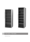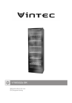
1
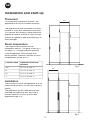
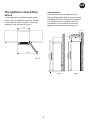
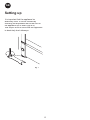
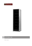
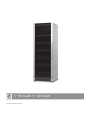
V 150 SG2E / V 190 SG2E
Instructions for use
GB
Thank you for purchasing your new wine
cooler from Vintec. Please note that these
instructions apply to all wine coolers in
the Vintec range. Illustrations and fittings
may therefore not necessarily correspond
exactly to your model.
you of how collection and recycling of such
units take place in your area.
Before use
Before operating your new appliance,
please read the following instructions carefully as they contain important information
on safety, installation, operation and maintenance. Keep the instructions for future
reference.
Warning
As the refrigerant used in this appliance is a
flammable gas (Isobutane R600a), special
care must be taken to prevent damage
to the refrigerant circuit and piping during
transport and installation.
On receipt, check to ensure that the appliance has not been damaged during
transport. Transport damage should be
reported to the local distributor before the
wine cooler is put to use.
If damage does occur, avoid sparks or
naked flame in the vicinity of the appliance,
ensure that the room is well ventilated,
disconnect the power supply, and contact
your supplier.
Remove the packaging. Clean the inside of
the cabinet using warm water with a mild
detergent. Rinse with clean water and dry
thoroughly (see cleaning instructions). Use
a soft cloth.
The unit must only be serviced by qualified technicians from an approved service
centre.
If during transport the appliance has been
laid down, or if it has been stored in cold
surroundings (colder than +5°C), it must be
allowed to stabilise in an upright position for
at least an hour before being switched on.
Old appliances
Old refrigerators and freezers are often
fitted with complicated latches that can
only be opened from the outside. If you
have one of these old units stored away
somewhere, or if you scrap one, remember
to destroy the latch first in order to prevent
children from being exposed to great danger by getting locked inside the unit.
Contents
Get to know your wine cooler...........3
Installation and start-up....................4
Reversible door.................................7
Electrical connection.........................8
Operation and function.....................9
Defrosting,
cleaning and maintenance..............11
Fault finding....................................12
Disposal
This appliance contains recyclable materials. Before disposing of the unit, detach the
plug from the cable and remove the door.
If the door is left on, the appliance is highly
dangerous for children at play.
Environmental regulations on disposal must
also be observed. When disposing of the
appliance you should contact your local authority technical department who will inform
2
GB
Get to know your wine cooler
Lighting
Charcoal filter
Wooden shelf
Sealing strip
Nameplate
Door handle
Kick plate
Control panel
Lock
Adjustable feet
fig.1
3
GB
Installation and start-up
Placement
600
600
For safety and operational reasons, the
appliance must not be installed outdoors.
615
600
The appliance should be placed on a level
surface in a dry, well ventilated room (max.
75% relative air humidity). Never place the
appliance close to sources of heat such as
cookers or radiators, and avoid placing it in
direct sunlight.
Room temperature
The climate class is stated on the
nameplate (see fig. 1 on page 3 and fig. 11
on page 13). This specifies the optimum
room temperature. Wine coolers with
winter position, however, function at room
temperatures as low as 5ºC.
Climate class
Optimum room temperature
SN
+10 ºC to +32 ºC
N
+16 ºC to +32 ºC
ST
+18 ºC to +38 ºC
T
+18 ºC to +43 ºC
fig. 2
600
615
Installation
The surface on which the appliance is to be
placed must be level. Do not use a frame or
similar.
The appliance can be installed as a freestanding unit against a wall, built into a
kitchen element, or lined up with other
appliances (figs 2-3).
fig. 3
4
GB
The appliance viewed from
above
Ventilation
It is important that the appliance be
well ventilated and that air can circulate
unhindered above, below and around it.
The figures below illustrate how the
necessary air circulation around the
appliance can be ensured (figs 5-6).
If the appliance is placed beside a wall,
there must be sufficient room for its door
to be opened wide enough to allow the
shelves to be pulled out (fig. 4).
615
50-100
50 -100
1650/1950
1560/1860
1075
fig. 4
fig. 5
5
fig. 6
GB
Setting up
It is important that the appliance be
absolutely level. It can be levelled by
screwing the adjustable feet at the front of
the appliance up or down (figs 8-9).
Use a spirit level to check that the appliance
is absolutely level sideways.
fig. 7
6
GB
Reversible door
The door can be changed from right-hinged to left-hinged and vice versa as follows:
1. Lay the appliance on its back and loosen
the upper hinge.
2. Remove the upper hinge.
3. Rotate the glass door through 180° (on
V 150 SG2E, pull the handle to loosen
it on the inside from beneath the sealing
strip).
4. Carefully remove the covers on the
side of the plinth using a flat-headed
screwdriver.
5. Pull up the hinge pin...
...and fit it on the opposite side.
6. Unscrew the lock pin using a flat-headed
screwdriver.
7. When the lock pin has been loosened
completely, pull it up together with the
lock cylinder and refit on opposite side.
8. Click the covers into place on the plinth
sides on the opposite side.
9. Fit the door onto the bottom pin, fit the
top hinge and tighten securely.
10. After reversing the door, it is important to check that the sealing strip provides a tight seal all the way round. If it does not, carefully heat
the strip all the way round using a hair dryer. Then ease the strip outwards slightly so that it forms a tight seal against the cabinet. Be
careful not to heat the strip so much that it melts!
7
GB
Electrical connection
The appliance is intended for connection
to alternating current. The required voltage (V) and frequency (Hz) are stated on
the nameplate inside the appliance. Power
must be connected via an independent wall
socket outlet.
If the mains lead has been damaged, it
must be replaced with a corresponding
type supplied by the manufacturer or an
approved service centre.
Technical data
This appliance complies with CE marking
regulations, directives and standards.
Low Voltage Directive 73/23/EEC.
EMC Directive 89/336/EEC.
8
GB
Operation and function
Light switch
On/off switch
fig. 9
Electronic controls
temperature display has a built-in filter
that simulates the actual temperature in
the bottles. The displayed temperature
is therefore not affected by transient
fluctuations in air temperature.
The electronic controls ensure that the set
temperatures are maintained at the top and
bottom of the cabinet. This is accomplished
by complex control of the refrigerating
system the heating element and the fan.
Following any power failure, the
temperature settings are automatically
recalled.
The electronic controls have the following
functions:
Temperature setting
The temperature is set using the two
buttons on the control panel. The upper
button is used to set the temperature at
the top of the cabinet. The lower button is
used to set the temperature at the bottom.
Deactivate the childproof lock by pressing
the button for 3 seconds. The display
then starts flashing and shows the current
temperature setting for the zone concerned.
This applies to both buttons/sections. When
the display starts flashing, the temperature
can be set by scrolling the setting between
22 and 5°C. When the desired setting is
displayed, release the button for 3 seconds.
The setting will then be stored and the
childproof lock reactivated.
• Temperature setting
• Temperature display
• Automatic defrosting
• Fault-finding, emergency and service
programs
• Low-temperature alarm
On/off switch
The light switch is used to select either
continuous illumination or illumination
only when the door is opened.
Note that the bottom section cannot be
given a higher temperature setting than
the top section. The highest available
temperature setting for the bottom section
is therefore identical to the actual setting for
the top section.
Temperature display
The display shows the actual temperature
at the top or bottom of the cabinet. To
switch the display between the top and
bottom sections, short-press the top
and bottom buttons respectively. The
9
GB
Low-temperature alarm
If the temperature has been below 2°C
for more than 1 hour, the display flashes
and Lo/actual temperature are alternately
shown. Wine cannot mature properly at
sub-zero temperatures.
Two-zone setting for serving temperature
Typical serving temperature settings for the
top and bottom sections are 16°C and 6°C
respectively. With these settings, a suitable
temperature gradient will be achieved in
the cabinet for the storage of various types
of wine distributed from top to bottom as
follows:
- heavy red wines +16 to +19°C
- rosé and light red wines +12 to +16°C
- white wines +10 to +12°C
- champagne and sparkling wines +6 to
+8°C
It is recommended that wine be served at a
temperature which is a couple of degrees
lower than the desired drinking temperature
as the wine will be warmed slightly when it
is poured into the glass.
Single-zone setting for long-term storage
For long-term wine storage, the top and bottom sections should both be set at 12°C.
With identical settings for the top and bottom sections, the controls will maintain an
even temperature throughout the cabinet.
However, the temperature in the room will
gradually affect the temperature in the
cabinet through its door and sides, creating
a slight temperature gradient from top to
bottom. The controls will maintain the set
temperature at the bottom of the cabinet,
and any deviation from the setting will
therefore occur at the top.
The difference will vary from 0 to 3°C, depending on the ambient temperature.
10
GB
Defrosting, cleaning and maintenance
Automatic defrosting
Replacing the light tube
The wine cooler is defrosted automatically.
Defrost water runs through a pipe and is
collected in a tray above the compressor
where the heat generated by the compressor causes it to evaporate. The defrost
water tray should be cleaned at intervals.
Disconnect the power by pressing the on/off
button. Remove the lamp cover using a
small flat-headed screwdriver. Replace the
PLC tube (11 W).
Refit the lamp cover, reconnect the power
supply and start the appliance by pressing
the on/off switch.
Cleaning
Switch off the appliance by pressing the
on/off button before cleaning it inside. The
cabinet is best cleaned using warm water
(max. 65°C) with a little mild detergent.
Never use cleaning agents that scour. Use
a soft cloth. Rinse with clean water and dry
thoroughly. The defrost water channel, in
which condensation from the evaporator
runs, is located at the bottom of the rear
inside wall of the cabinet and must be kept
clean. Add a few drops of disinfectant, e.g.
Rodalon, to the defrost water drain a couple
of times a year, and clean the drain using
a pipe cleaner or similar. Never use sharp
or pointed implements. The sealing strip
around the door must be cleaned regularly to prevent discolouration and prolong
service life. Use clean water. After cleaning
the sealing strip, check that it continues to
provide a tight seal. Dust collecting on the
condenser on the rear of the cabinet, the
compressor and in the compressor compartment is best removed using a vacuum
cleaner.
11
fig. 10
Fault finding
Fault
Possible cause
Remedy
The appliance is
“dead”!
The appliance is switched off.
Press the on/off switch.
Power failure; the fuse is blown;
the appliance is not plugged in
correctly.
Check that power is connected.
Reset the fuse.
Water collects in
the bottom of the
cabinet.
The defrost water pipe is
blocked.
Clean the defrost water channel
and the drain hole on the rear
wall of the cabinet.
Vibration or
bothersome noise.
The appliance is not level.
The appliance is resting against
other kitchen elements.
Level the appliance using a spirit
level.
Containers or bottles inside the
cabinet are rattling against one
another.
Move the appliance away from
the kitchen elements or appliances it is in contact with.
Move containers and/or bottles
apart.
Compressor runs
continuously.
High room temperature.
Ensure adequate ventilation.
E1 is shown on the
display.
The upper sensor is disconnected or short-circuited.
Call for service. The temperature
within the entire cabinet is maintained at the higher of the two
setpoints until the fault has been
corrected.
E2 is shown on the
display.
The lower sensor is disconnected Call for service. The temperature
or short-circuited.
within the entire cabinet is maintained at the higher of the two
setpoints until the fault has been
corrected.
ULO is shown on
the display.
The mains voltage is lower than
184 V.
UHI is shown on the
display.
The mains voltage is higher than
255 V.
Manufacturer reserves the right to alter specifications without prior
notice.
912086x0000.0083
06/04