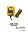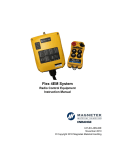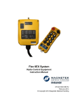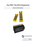
1
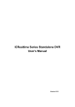
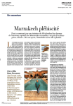
Flex 4EX System Radio Control Equipment Instruction Manual 0-TC-FLEX4E R4 December 2012 © Copyright 2012 Magnetek Material Handling Service Information Your New Radio System Thank you for your purchase of Magnetek’s Enrange™ Flex EX radio remote control system. Without a doubt, our Flex EX system is the ultimate solution for providing precise, undeterred, and safe control of your material. If your product ever needs modification or service, please contact one of our representatives at the following locations: U.S. Service Information For questions regarding service or technical information contact: 1.866.MAG.SERV 1.866.624.7378 World Headquarters: Magnetek, Inc. N49 W13650 Campbell Drive Menomonee Falls, WI 53051 Telephone: Website: e-mail: 1.800.288.8178 www.magnetekmh.com [email protected] Fax Numbers: Main: 1.800.298.3503 Sales: 1.262.783.3510 Service: 1.262.783.3508 Magnetek, Inc. has additional satellite locations for Canada and the United States. For more information, please visit http://www.magnetekmh.com. ©2012 MAGNETEK All rights reserved. This notice applies to all copyrighted materials included with this product, including, but not limited to, this manual and software embodied within the product. This manual is intended for the sole use of the person(s) to whom it was provided, and any unauthorized distribution of the manual or dispersal of its contents is strictly forbidden. This manual may not be reproduced in whole or in part by any means whatsoever without the expressed written permission of MAGNETEK. PRODUCT MANUAL SAFETY INFORMATION Magnetek, Inc. (Magnetek) offers a broad range of radio remote control products, control products and adjustable frequency drives, and industrial braking systems for material handling applications. This manual has been prepared by Magnetek to provide information and recommendations for the installation, use, operation and service of Magnetek’s material handling products and systems (Magnetek Products). Anyone who uses, operates, maintains, services, installs or owns Magnetek Products should know, understand, and follow the instructions and safety recommendations in this manual for Magnetek Products. The recommendations in this manual do not take precedence over any of the following requirements relating to cranes, hoists lifting devices or other material handling equipment which use or include Magnetek Products: Instructions, manuals, and safety warnings of the manufacturers of the equipment where the radio system is used, Plant safety rules and procedures of the employers and the owners of facilities where the Magnetek Products are being used, Regulations issued by the Occupational Health and Safety Administration (OSHA), Applicable local, state or federal codes, ordinances, standards and requirements, or Safety standards and practices for the industries in which Magnetek Products are used. This manual does not include or address the specific instructions and safety warnings of these manufacturers or any of the other requirements listed above. It is the responsibility of the owners, users and operators of the Magnetek Products to know, understand and follow all of these requirements. It is the responsibility of the employer to make its employees aware of all of the above listed requirements and to make certain that all operators are properly trained. No one should use Magnetek Products prior to becoming familiar with and being trained in these requirements and the instructions and safety recommendations in this manual. WARRANTY INFORMATION For information on Magnetek’s product warranties by product type, please visit www.magnetekmh.com. Table of Contents 1. INTRODUCTION ......................................................................................................... 3 2. RADIO CONTROLLED SAFETY................................................................................. 4 2.1 CRITICAL INSTALLATION CONSIDERATIONS .................................................... 5 2.2 GENERAL ............................................................................................................. 5 2.3 PERSONS AUTHORIZED TO OPERATE RADIO CONTROLLED CRANES ........ 5 2.4 SAFETY INFORMATION AND RECOMMENDED TRAINING FOR RADIO CONTROLLED EQUIPMENT OPERATORS ............................................................... 6 2.5 TRANSMITTER UNIT ............................................................................................ 7 2.6 PRE-OPERATION TEST ....................................................................................... 7 2.7 BATTERIES ........................................................................................................... 8 2.8 BATTERY HANDLING ........................................................................................... 8 2.9 BATTERY CHARGING .......................................................................................... 8 2.10 BATTERY DISPOSAL .......................................................................................... 8 2.11 SPECIFIC SYSTEM WARNINGS ........................................................................ 9 3. GENERAL SYSTEM INFORMATION ........................................................................ 10 3.1 TRANSMITTER HANDSET ................................................................................. 10 3.1.1 External Illustration ........................................................................................ 10 3.1.2 Internal Illustration ......................................................................................... 11 3.2 RECEIVER UNIT ................................................................................................. 12 3.2.1 External Illustration ........................................................................................ 12 3.2.2 Internal Illustration ......................................................................................... 13 4. FUNCTION SETTINGS ............................................................................................. 14 4.1 TRANSMITTER HANDSET ................................................................................. 14 4.1.1 System Channel Settings .............................................................................. 14 4.1.2 Push Button Functions with LED Displays .................................................... 15 4.1.2.1 Transmitter Toggle Push Button Settings ................................................ 15 4.1.2.2 A/B Selector Push Button Settings ......................................................... 16 4.1.3 Channel Change via Push Buttons ............................................................... 17 4.1.4 Optional 4-Digit Security Code ...................................................................... 18 4.1.5 I-CHIP ........................................................................................................... 19 4.2 RECEIVER UNIT ................................................................................................. 20 4.2.1 System Channel Settings .............................................................................. 20 4.2.2 Output Relay Configurations ......................................................................... 21 4.2.2.1 Output Relay Types ................................................................................ 21 4.2.2.2 Output Relay Actions at 2nd Speed ......................................................... 21 4.2.2.3 ON/OFF Push Button Function ............................................................... 22 4.2.2.4 START/AUX Function ............................................................................. 22 4.2.2.5 Magnet ON/OFF Push Button Function .................................................. 23 4.2.2.6 Brake Function ....................................................................................... 23 4.2.2.7 Momentary Contact ................................................................................ 23 4.2.2.8 Toggled Contact ...................................................................................... 23 4.2.2.9 3rd Speed Push Button Function ............................................................. 23 4.2.2.10 Auxiliary STOP Push Button Function .................................................. 24 4.2.3 Receiver Auto-Scanning Settings .................................................................. 24 4.2.4 Dip-Switch Settings ....................................................................................... 25 Flex 4EX System Instruction Manual December 2012 1 of 39 4.2.4.1 Interlocked Functions ............................................................................. 25 4.2.4.2 Non-Interlocked Functions ...................................................................... 26 4.2.5 Jumper Settings ............................................................................................ 27 4.2.6 I-CHIP Programming Port ............................................................................. 28 4.2.7 Fuse Ratings ................................................................................................. 28 5. SYSTEM CHANNELS TABLE ................................................................................... 29 6. RECEVIER INSTALLATION ...................................................................................... 30 6.1 OUTPUT RELAY CONTACT DIAGRAM .............................................................. 30 6.2 PRE-INSTALLATION PRECAUTIONS ................................................................ 31 6.3 STEP-BY-STEP INSTALLATION ......................................................................... 31 6.4 SYSTEM TESTING ............................................................................................. 32 7. OPERATING PROCEDURE...................................................................................... 33 7.1 TRANSMITTER OPERATION ............................................................................. 33 7.1.1 General Operating Procedure ....................................................................... 33 7.1.2 A/B Selector Push Button Operating Procedure ............................................ 34 7.1.3 3rd Speed Push Button Operating Procedure ................................................ 34 7.1.4 Automatic Channel Scanning Operating Procedure ...................................... 35 7.1.5 Changing Transmitter Batteries ..................................................................... 35 7.2 STATUS LIGHT INDICATORS & WARNINGS ..................................................... 36 7.2.1 Transmitter STATUS Light Indication............................................................. 36 7.2.2 Receiver STATUS Light Indication ................................................................ 37 7.2.3 Receiver SQ Light Indication ......................................................................... 37 7.2.4 Receiver POWER Light Indication ................................................................ 37 7.2.5 Receiver COM Light Indication...................................................................... 37 7.3 TROUBLE SHOOTING TIPS ............................................................................... 38 8. SYSTEM SPECIFICATIONS ..................................................................................... 39 Flex 4EX System Instruction Manual December 2012 2 of 39 1. INTRODUCTION The Flex radio remote control systems are designed for control of industrial equipment and machinery such as overhead traveling cranes, jib cranes, gantry cranes, tower cranes, electric hoists, winches, monorails, conveyor belts, mining equipment and other material handling equipment where wireless control is preferred. Each Flex system consists of a transmitter handset and receiver unit. Other standard-equipped accessories include transmitter waist belt, spare transmitter power key, clear vinyl pouch, “AA” alkaline batteries, compass direction decal sheet and user’s manual. List of notable features include: 62 user-programmable channels – Advanced synthesized RF controls with 62 built-in channels; there are no more fixed channels and fragile quartz crystals to break. Automatic channel scanning receiver – No more hassle of climbing up the crane to change receiver channels. Over one million unique ID codes (20bit) – Each and every Flex system has its own unique ID codes and serial number, never repeats. Advanced controls – The Flex system utilizes advanced microprocessor controls with 32bit CRC and Hamming Code, which provide ultra fast, safe, precise, and error-free encoding and decoding. Unique I-CHIP design – The I-CHIP functions in a way that is very similar to SIM cards used on mobile phones, with the ability to transfer system information and settings from one transmitter to another without the hassle of resetting the spares. Reliable push buttons – The in-house designed push buttons with gold-plated contacts are rated for more than one million press cycles. Low power consumption – Requires only two “AA” Alkaline batteries for more than 100 hours of operating time between replacements. Ultra-durable nylon and fiberglass composite enclosures – Highly resistant to breakage and deformation even in the most abusive environments. Full compliance – All systems are fully compliant with the FCC Part-15 Rules, European Directives (Safety, EMC, R&TTE, Machinery), and Industry Canada Specifications (IC). Flex 4EX System Instruction Manual December 2012 3 of 39 2. RADIO CONTROLLED SAFETY WARNINGS and CAUTIONS Throughout this document WARNING and CAUTION statements have been deliberately placed to highlight items critical to the protection of personnel and equipment. WARNING – A warning highlights an essential operating or maintenance procedure, practice, etc. which if not strictly observed, could result in injury or death of personnel, or long term physical hazards. Warnings are highlighted as shown below: WARNING CAUTION – A caution highlights an essential operating or maintenance procedure, practice, etc. which if not strictly observed, could result in damage to, or destruction of equipment, or loss of functional effectiveness. Cautions are highlighted as shown below: CAUTION WARNINGS and CAUTIONS SHOULD NEVER BE DISREGARDED. The safety rules in this section are not intended to replace any rules or regulations of any applicable local, state, or federal governing organizations. Always follow your local lockout and tagout procedure when maintaining any radio equipment. The following information is intended to be used in conjunction with other rules or regulations already in existence. It is important to read all of the safety information contained in this section before installing or operating the Radio Control System. Flex 4EX System Instruction Manual December 2012 4 of 39 2.1 CRITICAL INSTALLATION CONSIDERATIONS WARNING PRIOR TO INSTALLATION AND OPERATION OF THIS EQUIPMENT, READ AND DEVELOP AN UNDERSTANDING OF THE CONTENTS OF THIS MANUAL AND THE OPERATION MANUAL OF THE EQUIPMENT OR DEVICE TO WHICH THIS EQUIPMENT WILL BE INTERFACED. FAILURE TO FOLLOW THIS WARNING COULD RESULT IN SERIOUS INJURY OR DEATH AND DAMAGE TO EQUIPMENT. ALL EQUIPMENT MUST HAVE A MAINLINE CONTACTOR INSTALLED AND ALL TRACKED CRANES, HOISTS, LIFTING DEVICES AND SIMILAR EQUIPMENT MUST HAVE A BRAKE INSTALLED. FAILURE TO FOLLOW THIS WARNING COULD RESULT IN SERIOUS INJURY OR DEATH AND DAMAGE TO EQUIPMENT. AN AUDIBLE AND/OR VISUAL WARNING MEANS MUST BE PROVIDED ON ALL REMOTE CONTROLLED EQUIPMENT AS REQUIRED BY CODE, REGULATION, OR INDUSTRY STANDARD. THESE AUDIBLE AND/OR VISUAL WARNING DEVICES MUST MEET ALL GOVERNMENTAL REQUIREMENTS. FAILURE TO FOLLOW THIS WARNING COULD RESULT IN SERIOUS INJURY OR DEATH AND DAMAGE TO EQUIPMENT. FOLLOW YOUR LOCAL LOCKOUT TAGOUT PROCEDURE BEFORE MAINTAINING ANY REMOTE CONTROLLED EQUIPMENT. ALWAYS REMOVE ALL ELECTRICAL POWER FROM THE CRANE, HOIST, LIFTING DEVICE OR SIMILAR EQUIPMENT BEFORE ATTEMPTING ANY INSTALLATION PROCEDURES. DE-ENERGIZE AND TAGOUT ALL SOURCES OF ELECTRICAL POWER BEFORE TOUCH-TESTING ANY EQUIPMENT. FAILURE TO FOLLOW THIS WARNING COULD RESULT IN SERIOUS INJURY OR DEATH AND DAMAGE TO EQUIPMENT. THE DIRECT OUTPUTS OF THIS PRODUCT ARE NOT DESIGNED TO INTERFACE DIRECTLY TO TWO STATE SAFETY CRITICAL MAINTAINED FUNCTIONS, I.E., MAGNETS, VACUUM LIFTS, PUMPS, EMERGENCY EQUIPMENT, ETC. A MECHANICALLY LOCKING INTERMEDIATE RELAY SYSTEM WITH SEPARATE POWER CONSIDERATIONS MUST BE PROVIDED. FAILURE TO FOLLOW THIS WARNING COULD RESULT IN SERIOUS INJURY OR DEATH OR DAMAGE TO EQUIPMENT. 2.2 GENERAL Radio controlled material handling equipment operates in several directions. Cranes, hoists, lifting devices and other material handling equipment can be large, and operate at high speeds. Quite frequently, the equipment is operated in areas where people are working in close proximity to the material handling equipment. The operator must exercise extreme caution at all times. Workers must constantly be alert to avoid accidents. The following recommendations have been included to indicate how careful and thoughtful actions may prevent injuries, damage to equipment, or even save a life. 2.3 PERSONS AUTHORIZED TO OPERATE RADIO CONTROLLED CRANES Only properly trained persons designated by management should be permitted to operate radio controlled equipment. Radio controlled cranes, hoists, lifting devices and other material handling equipment should not be operated by any person who cannot read or understand signs, notices and operating instructions that pertain to the equipment. Radio controlled equipment should not be operated by any person with insufficient eyesight or hearing or by any person who may be suffering from a disorder or illness, is taking any medication that may cause loss of equipment control, or is under the influence of alcohol or drugs. Flex 4EX System Instruction Manual December 2012 5 of 39 2.4 SAFETY INFORMATION AND RECOMMENDED TRAINING FOR RADIO CONTROLLED EQUIPMENT OPERATORS Anyone being trained to operate radio controlled equipment should possess as a minimum the following knowledge and skills before using the radio controlled equipment. The operator should: have knowledge of hazards pertaining to equipment operation have knowledge of safety rules for radio controlled equipment have the ability to judge distance of moving objects know how to properly test prior to operation be trained in the safe operation of the radio transmitter as it pertains to the crane, hoist, lifting device or other material handling equipment being operated have knowledge of the use of equipment warning lights and alarms have knowledge of the proper storage space for a radio control transmitter when not in use be trained in transferring a radio control transmitter to another person be trained how and when to report unsafe or unusual operating conditions test the transmitter emergency stop and all warning devices prior to operation; testing should be done on each shift, without a load be thoroughly trained and knowledgeable in proper and safe operation of the crane, hoist, lifting device, or other material handling equipment that utilizes the radio control know how to keep the operator and other people clear of lifted loads and to avoid “pinch” points continuously watch and monitor status of lifted loads know and follow cable and hook inspection procedures know and follow the local lockout and tagout procedures when servicing radio controlled equipment know and follow all applicable operating and maintenance manuals, safety procedures, regulatory requirements, and industry standards and codes The operator shall not: lift or move more than the rated load operate the material handling equipment if the direction of travel or function engaged does not agree with what is indicated on the controller use the crane, hoist or lifting device to lift, support or transport people lift or carry any loads over people operate the crane, hoist or lifting device unless all persons, including the operator, are and remain clear of the supported load and any potential pinch points operate a crane, hoist or lifting device when the device is not centered over the load Flex 4EX System Instruction Manual December 2012 6 of 39 operate a crane, hoist or lifting device if the chain or wire rope is not seated properly in the sprockets, drum or sheave operate any damaged or malfunctioning crane, hoist, lifting device or other material handling equipment change any settings or controls without authorization and proper training remove or obscure any warning or safety labels or tags leave any load unattended while lifted leave power on the radio controlled equipment when the equipment is not in operation operate any material handling equipment using a damaged controller because the unit may be unsafe operate manual motions with other than manual power operate radio controlled equipment when low battery indicator is on WARNING THE OPERATOR SHOULD NOT ATTEMPT TO REPAIR ANY RADIO CONTROLLER. IF ANY PRODUCT PERFORMANCE OR SAFETY CONCERNS ARE OBSERVED, THE EQUIPMENT SHOULD IMMEDIATELY BE TAKEN OUT OF SERVICE AND BE REPORTED TO THE SUPERVISOR. DAMAGED AND INOPERABLE RADIO CONTROLLER EQUIPMENT SHOULD BE RETURNED TO MAGNETEK FOR EVALUATION AND REPAIR. FAILURE TO FOLLOW THIS WARNING COULD RESULT IN SERIOUS INJURY OR DEATH AND DAMAGE TO EQUIPMENT. 2.5 TRANSMITTER UNIT Transmitter switches should never be mechanically blocked ON or OFF. When not in use, the operator should turn the transmitter OFF. A secure storage space should be provided for the transmitter unit, and the transmitter unit should always be placed there when not in use. This precaution will help prevent unauthorized people from operating the material handling equipment. Spare transmitters should be stored in a secure storage space and only removed from the storage space after the current transmitter in use has been turned OFF, taken out of the service area and secured. 2.6 PRE-OPERATION TEST At the start of each work shift, or when a new operator takes control of the crane, operators should do, as a minimum, the following steps before making lifts with any crane or hoist: Test all warning devices. Test all direction and speed controls. Test the transmitter emergency stop. Flex 4EX System Instruction Manual December 2012 7 of 39 2.7 BATTERIES WARNING KNOW AND FOLLOW PROPER BATTERY HANDLING, CHARGING AND DISPOSAL PROCEDURES. IMPROPER BATTERY PROCEDURES CAN CAUSE BATTERIES TO EXPLODE OR DO OTHER SERIOUS DAMAGE. FAILURE TO FOLLOW THIS WARNING COULD RESULT IN SERIOUS INJURY OR DEATH AND DAMAGE TO EQUIPMENT. 2.8 BATTERY HANDLING Use only batteries approved by Magnetek for the specific product. Do not dispose of a battery pack in fire; it may explode. Do not attempt to open the battery pack. Do not short circuit the battery. For intrinsically safe environments only use specified Magnetek intrinsically safe batteries. Keep the battery pack environment cool during charging operation and storage (i.e., not in direct sunlight or close to a heating source). 2.9 BATTERY CHARGING For those transmitters equipped with battery chargers, please familiarize all users with the instructions of the charger before attempting to use. Do not attempt to charge non-rechargeable battery packs. Avoid charging partially discharged rechargeable batteries to help prolong battery cycle life. Avoid charging the battery pack for more than 24 hours at a time. Do not charge batteries in a hazardous environment. Do not short the charger. Do not attempt to charge a damaged battery. Use only Magnetek approved chargers for the appropriate battery pack. Do not attempt to use a battery that is leaking, swollen or corroded. Charger units are not intended for outdoor use. Use only indoors. 2.10 BATTERY DISPOSAL Before disposing of batteries consult local and governmental regulatory requirements for proper disposal procedure. Flex 4EX System Instruction Manual December 2012 8 of 39 2.11 SPECIFIC SYSTEM WARNINGS Below are some specific operating safety tips that should be strictly followed when operating a Flex 4EX system: 1. Check the Status LED on the transmitter for any signs of low battery power (refer to page 36). 2. Check the Status LED on the transmitter for any signs of irregularities (refer to page 36). 3. Make sure the system is not set to the same channel as any other Flex systems in use within a distance of 300 meters (900 feet). 4. Never operate equipment with two transmitter handsets at the same time unless they are programmed to do so. Flex 4EX System Instruction Manual December 2012 9 of 39 3. GENERAL SYSTEM INFORMATION 3.1 TRANSMITTER HANDSET 3.1.1 External Illustration (Fig. 01) 1. 2. 3. 4. 5. 6. Emergency Stop Button Removable Power Key Switch Push Button #2 Push Button #4 Push Button #1 Push Button #3 (Fig. 02) 7. 8. 9. 10. 11. 12. Strap Ring System Information System Channel Crane Number Battery Cover FCC Information Flex 4EX System Instruction Manual December 2012 10 of 39 3.1.2 Internal Illustration (Fig. 03) 1. 2. 3. 4. 5. Encoder Board Aerial Antenna Transmitting Module Status LED Display Function LED Displays (Fig. 04) 6. 7. 8. 9. I-CHIP Function Dip-Switch Channel Dip-Switch Battery Contact Mechanism Flex 4EX System Instruction Manual December 2012 11 of 39 3.2 RECEIVER UNIT 3.2.1 External Illustration 1 2 3 4 5 6 7 (Fig. 05) 1. 2. 3. 4. External Antenna Jack (optional) Power LED Display Status LED Display SQ LED Display 5. 6. 7. COM LED Display Output Contact Diagram Cord Grip Flex 4EX System Instruction Manual December 2012 12 of 39 3.2.2 Internal Illustration 1 I-CHIP PORT 2 JP7 JP6 JP5 JP4 JP3 JP2 JP1 SYSTEM FUNCTIONS TEST 3 4 (Fig. 06) 1. 2. Receiving Module Decoder + Relay Board 3. 4. AC Line Filter + Relay Board Power Transformer Flex 4EX System Instruction Manual December 2012 13 of 39 4. FUNCTION SETTINGS 4.1 TRANSMITTER HANDSET 4.1.1 System Channel Settings CHANNEL 1 2 3 4 5 6 7 8 (Fig. 07) Set the transmitter channel by adjusting the channel dip-switch located on the backside of the transmitter encoder board (refer to Fig. 07 above). Only the first six (6) positions are used for channel programming (refer to Fig. 08 below). The system channels table located on page 29 illustrates which dip-switch setting corresponds to which channel. Once the transmitter channel is altered, make sure to change the receiver channel as well. The channel on both the transmitter and the receiver must be identical in order for the system to work. To change the receiver channel please refer to page 20. Example: Top slot → “1” Bottom slot → “0” (Fig. 08) 1 2 3 4 5 6 7 8 The above dip-switch setting “1 0 0 1 0 0” corresponds to “channel 36” in the system channels table on page 29. Flex 4EX System Instruction Manual December 2012 14 of 39 4.1.2 Push Button Functions with LED Displays 4.1.2.1 Transmitter Toggle Push Button Settings Set the transmitter toggle (latching output relay) function by adjusting the 8-position function dip-switch located on the backside of the transmitter encoder board (refer to Fig. 09 & 10 below). The LED 1 through LED 4 shown inside the shaded box (see below) illustrates which LED on the transmitter will light up when the designated push button (PB1-PB4) is pressed. LED 4 LED 3 LED 2 LED 1 FUNCTION 1 2 3 4 5 6 7 8 (Fig. 09) (Fig.10) DIP PB1 PB2 PB3 PB4 1 00000000 Normal Normal Normal Normal 2 00000001 Normal Normal Normal LED 4 3 00000010 Normal Normal LED 3 LED 4 4 00000011 Normal LED 2 LED 3 LED 4 5 00000100 LED 1 LED 2 LED 3 LED 4 * PB1…PB4 → Push button number * Normal → Normal momentary contact * LED 1…LED 4 → Transmitter toggled with designated LED Display Flex 4EX System Instruction Manual December 2012 15 of 39 4.1.2.2 A/B Selector Push Button Settings There are four (4) different types of A/B selector sequences available on the Flex system. Choose the one that is most suitable for your application. Type-A selector sequence Type-B selector sequence Type-C selector sequence Type-D selector sequence : : : : A+B → A → B → A+B … Off → A → B → Off → A → B … A → B → A+B → A → B → A+B … Off → A → B → A+B → Off → A → B → A+B … DIP PB1 PB2 PB3 PB4 6 00011101 Normal Normal A/1&2 Normal 7 00011110 Normal Normal B/1&2 Normal 8 00011111 Normal Normal C/1&2 Normal 9 00100000 Normal Normal D/1&2 Normal 10 00100001 Normal Normal Normal A/3&4 11 00100010 Normal Normal Normal B/3&4 12 00100011 Normal Normal Normal C/3&4 13 00100100 Normal Normal Normal D/3&4 14 00100101 Normal Normal A/1&2 A/3&4 15 00100110 Normal Normal A/1&2 B/3&4 16 00100111 Normal Normal A/1&2 C/3&4 17 00101000 Normal Normal A/1&2 D/3&4 18 00101001 Normal Normal B/1&2 B/3&4 19 00101010 Normal Normal B/1&2 C/3&4 20 00101011 Normal Normal B/1&2 D/3&4 21 00101100 Normal Normal C/1&2 C/3&4 22 00101101 Normal Normal C/1&2 D/3&4 23 00101110 Normal Normal D/1&2 D/3&4 * PB1…PB4 → Push button number * Normal → Normal momentary contact * A/1&2…D/3&4 → A/B Selector type with designated LED Display (LED 1&2 or LED 3&4) Flex 4EX System Instruction Manual December 2012 16 of 39 4.1.3 Channel Change via Push Buttons Other than the CHANNEL dip-switch on the encoder board, the transmitter channel can also be changed directly on the push buttons. Please refer to the instructions below on how to change the transmitter channel via push buttons. a. Press and hold PB1, PB2 and PB3 and rotate the power key to START position at the same time. A series of green and red blinks will appear on the Status LED showing the current channel setting. A green blink represents the tens (+10) and a red blink represents the units (+1). Examples: 2 green blinks followed by 5 red blinks represents channel 25. 6 red blinks represents channel 06. + b. Select a new channel by pressing PB1 and PB2 on the transmitter. Press PB1 to increment the units (+1) and PB2 to increment the tens (+10). Examples: Press PB2 two times and then PB1 four times will give you channel 24. Press PB1 nine times with give you channel 09. c. When finished, the newly selected channel will appear on the Status LED via series of green and red blinks again. d. Exit the channel programming by turning off the transmitter power. e. Make sure the receiver channel is set identical to the transmitter. Please refer to page 20 and page 35 on how to change the receiver channel. f. Please note that when the CHANNEL dip-switch inside the transmitter is changed, the priority will revert back to the new channel set on the CHANNEL dip-switch. g. Please note that when the channel is set beyond channel 62 via PB1 and PB2 (i.e. channel 63, 68, 88, etc…), the system will recognize it as channel 62. Flex 4EX System Instruction Manual December 2012 17 of 39 4.1.4 Optional 4-Digit Security Code The 4-digit Security Code is an optional feature that can be programmed into the transmitter to allow operation only to those who know the code. If this feature is desired, set up as follows: Prior to rotating the transmitter power key-switch to START position to begin operation, you first enter a 4-digit security code in order to proceed further. When this 4-digit security code is entered correctly, a green light will appear on the Status LED. Please refer to the instruction below on how to program the 4-digit security code. a. Release E-Stop, then press and hold PB1, PB2, PB3 and PB4 (all at once), and then rotate the power key to START position. + b. A constant orange light will appear on the Status LED telling you that you are in the security code programming mode. c. For newly purchased systems with the security code function deactivated (default setting), press PB1 four times (1111) to activate the security code function. At this time the Status LED on the transmitter will blink orange slowly telling you that the 4 digits entered is correct. Then select your own 4-digit security code by pressing PB1, PB2, PB3 or PB4 on the transmitter (four presses randomly). At this time, fast orange blinks are displayed on the Status LED telling you to reconfirm the 4-digit security code you have just entered. A green light will appear once you have re-entered the same 4-digit security code again (programming completed). If any mistake is made during this process, or if a red light is shown on the Status LED after you have re-entered the security code (incorrect input), or even if you believe you have entered the correct code but the transmitter fails to work properly, then you must reset the transmitter power (by powercycling the transmitter*) and then repeat steps a, b and c again. *NOTE: To power-cycle the transmitter, you must first remove, then reinstall the batteries. Simply turning the power switch off, then on will NOT properly clear the memory. This process must be used for any errors regarding proper transmitter operation (not just for security code settings). Steps: Press and hold PB1~PB4 and rotate power key to START position → constant orange → press PB1 four times (for new systems) or 4-digit security code → slow orange blinks → enter the new 4-digit security code → fast orange blinks → re-enter the same 4digit security code again → green light. d. e. If you wish to cancel the security code function, then repeat steps a, b, c above and press PB1 four times as your new security code (security code function disabled). If you do not remember the 4-digit security code, then you must contact your dealer or distributor for further assistance. Flex 4EX System Instruction Manual December 2012 18 of 39 4.1.5 I-CHIP The I-CHIP functions in a way that is very similar to a SIM card inside a mobile phone, which stores system information such as your telephone number, account number, phone book and other settings. I-CHIP works exactly the same way, as it stores information such as system serial number/ID code, channel and push button configurations. When replacing a transmitter handset, just take the I-CHIP out of the old transmitter and install it into the new one (refer to Fig. 11 below). For complete information transfer, make sure both the Channel and Function dip-switch is set to all “1”. If both dip-switches are set to all “1”, then the transmitter will operate according to the push button configurations and channel stored inside the I-CHIP. If both Channel and Function dip-switch is set to other values other than all “1”, then the transmitter will operate according to the channel and push button configurations set on these two dip-switches, not the ones stored inside the I-CHIP. Every time when the settings on these two dip-switches have changed, the new settings will be stored into the I-CHIP automatically. In this case the previous channel and push button configurations stored inside the I-CHIP will be replaced by the new settings. For safety purposes, the system serial number/ID code stored inside the I-CHIP can not be changed directly on the transmitter encoder board. Only channels and push button configurations can be changed directly on the encoder board via Channel and Function dipswitches. There are only two ways that you can change transmitter serial number/ID code: via I-CHIP programming port located on the decoder module inside the receiver unit, (please refer to page 28 on how to program the I-CHIP (serial number/ID code) via the receiver unit); or via an external I-CHIP programmer or duplicator unit available from the factory. Please ask your local dealers for assistance if your system requires serial number/ID code adjustments. (Fig. 11) Flex 4EX System Instruction Manual December 2012 19 of 39 4.2 RECEIVER UNIT 4.2.1 System Channel Settings EXT INT 1 2 3 4 5 6 7 8 (Fig. 12) Even though the Flex system is equipped with an automatic channel scanning mode, the user can also set the receiver channel manually. Please refer to page 35 on how automatic channel scanning receiver works. Set the receiver channel by adjusting the channel dip-switch located on the receiver module (refer to Fig. 12 above). Only the first six (6) positions are used for channel programming (refer to Fig. 13 below). The system channels table located on page 29 illustrates which dipswitch setting corresponds to which channel. Once the receiver channel is altered, make sure to change transmitter channel as well. The channel on both transmitter and receiver must be identical in order for system to work. To change the transmitter channel please refer to page 14. Example: Top slot → “1” Bottom slot → “0” 1 2 3 4 5 6 7 8 (Fig. 13) The above dip-switch setting “1 0 0 1 0 0” corresponds to “channel 36” in the system channels table on page 29. Flex 4EX System Instruction Manual December 2012 20 of 39 4.2.2 Output Relay Configurations 4.2.2.1 Output Relay Types Three (3) output relays per motion – shared 2nd speed output relay Output relays with Forward 1st speed (F1), Reverse 1st speed (R1) and Forward/Reverse 2nd speed (F/R2). Forward and Reverse 2nd speed (F/R2) shared the same output relay. F1 R1 F/R2 Four (4) output relays per motion – separate 1st and 2nd speed output relays Output relays with Forward 1st speed (F1), Reverse 1st speed (R1), Forward 2nd speed (F2) and Reverse 2nd speed (R2). Forward and Reverse 2nd speed with separate output relays. F1 R1 F2 R2 4.2.2.2 Output Relay Actions at 2nd Speed 3-output relays configuration with Closed/Closed contact at 2nd speed At 2nd speed, both 1st speed (F1 or R1) and 2nd speed (F/R2) output relays are closed (refer to page 25 on how to set to this function). st Forward 1 speed push button pressed nd Forward 2 speed push button pressed ↓ ↓ F1 R1 F/R2 F1 R1 F/R2 Flex 4EX System Instruction Manual December 2012 21 of 39 4-output relays configuration with Opened/Closed contact at 2nd speed At 2nd speed, only the 2nd speed (F2 or R2) output relay is closed (refer to page 25 on how to set to this function). st nd Forward 1 speed push button pressed Forward 2 speed push button pressed ↓ ↓ F1 R1 F2 R2 F1 R1 F2 R2 4-output relays configuration with Closed/Closed contact at 2nd speed At 2nd speed, both 1st speed (F1 or R1) and 2nd speed (F2 or R2) output relays are closed (refer to page 25 on how to set to this function). st nd Forward 1 speed push button pressed Forward 2 speed push button pressed ↓ ↓ F1 R1 F2 R2 F1 R1 F2 R2 4.2.2.3 ON/OFF Push Button Function The user can set any of the two adjacent push buttons on the transmitter to behave like a mechanical ON & OFF rocker switch (refer to page 25 on how to set to this function). When the “On” output relay is closed (“On” push button pressed), the “Off” output relay will open automatically, or vice versa. OFF ON 4.2.2.4 START/AUX Function After initiating the START function the Start position will become an auxiliary function with momentary contact. For auxiliary applications such as horns or buzzers, please connect it to the FUNC output relay (wire #5) located inside the receiver unit. Flex 4EX System Instruction Manual December 2012 22 of 39 4.2.2.5 Magnet ON/OFF Push Button Function The user can set any of the two adjacent push buttons on the transmitter to control a magnet. To activate the magnet just press the push button with the Magnet symbol. To deactivate the magnet, for safety purpose, you must first press and hold the Magnet push button and then press the OFF push button. Pressing the OFF push button by itself can not deactivate the magnet (refer to page 25 on how to set to this function). OFF 4.2.2.6 Brake Function When the transmitter push button is released from 2nd speed up to 1st speed, both 1st and 2nd speed output relays will open for up to 1.0 second and then with 1st speed output relay closed thereafter (refer to page 25 on how to set to this function). 4.2.2.7 Momentary Contact When the push button is released, the output relay that corresponds to that push button will open (refer to page 26 on how to set to this function). This type of contact is usually applied to external application such as horns or buzzers. 4.2.2.8 Toggled Contact When the push button is released, the output relay that corresponds to that push button will remain closed (maintained contact) until next time the user presses the same push button again (refer to page 26 on how to set to this function). This type of contact is usually applied to external application such as lights. 4.2.2.9 3rd Speed Push Button Function This function allows the crane to travel an additional step beyond 2nd speed. For example, if the operator is pressing the “UP” push button down to 2nd speed, pressing the 3rd speed push button (with “UP” push button still being held at 2nd speed) will toggle between 2nd speed and 3rd speed (refer to page 26 on how to set to this function). 3rd SPEED Flex 4EX System Instruction Manual December 2012 23 of 39 4.2.2.10 Auxiliary STOP Push Button Function The auxiliary STOP function acts as a 2nd emergency stop button. Other than by emergency stop button and transmitter power key switch, the receiver MAIN is also deactivated when this auxiliary stop push button is pressed (refer to page 26 on how to set to this function). Aux STOP 4.2.3 Receiver Auto-Scanning Settings Receiver Channel Dip-switch ↓ (1) → Scans all 62 channels (manufacture preset) For standard operation → Single fixed channel Auto scanning function disabled → Scanning 2 channels only* → Scanning 3 channels only 1 2 3 4 5 6 7 8 (2) 1 2 3 4 5 6 7 8 (3) 1 2 3 4 5 6 7 8 (4) 1 2 3 4 5 6 7 8 * If the first 6 dip-switch positions on the receiving module is set to Ch.01 (“000000” or “000001”), when set to 2-channel scanning (type-3 above), then the receiver will only scan Ch.01 and Ch.02. Flex 4EX System Instruction Manual December 2012 24 of 39 4.2.4 Dip-Switch Settings 4.2.4.1 Interlocked Functions Interlocked means the two adjacent push buttons can not be activated simultaneously as they will cancel each other out. Interlocked settings are usually applied to forward and reverse motions. Each dip-switch on the decoder module corresponds to one (1) motion or two (2) adjacent push buttons (refer to Fig. 14 & 15 below). Only the first seven (7) dip-switch positions are used (counting from left to right); the 8th dip-switch position (far right) is not used. I-CHIP PORT JP6 JP7 JP3 JP4 JP5 JP1 JP2 PB3 & PB4 1234567 8 RELAY FUNCTIONS PB1 & PB2 (Fig. 14) 1234567 8 1 2 3 4 5 6 7 8 SYSTEM FUNCTIONS TEST RELAY FUNCTIONS 1234567 8 PB5 & PB6 (Fig. 15) ▇ Manufacture preset Dip Settings Function Descriptions # of Relays Used 0000000 Normal (single speed only, F2 & R2 relays not used) 2 0000001 Closed/Closed Relay Action at 2nd Speed (separate 2nd speed relay) 4 0000010 Closed/Closed Relay Action at 2nd Speed (shared 2nd speed relay) 3 0000011 Opened/Closed Relay Action at 2nd Speed (separate 2nd speed relay) 4 0000110 On (right button) & Off (left button) 2 0001000 On & Off -- affected by the E-stop command. When E-stop command is initiated, the Off relay is activated. 2 0001001 On + Start / Off + Start -- Prior to pressing the button you must first rotate and hold the power key switch at START position to activate On or Off relays. 2 0000111 Safety Magnet On & Off 2 0001010 FWD/REV toggled (latched). 2 0001011 FWD/REV toggled (latched) and affected by the E-stop command. 2 0100001 Closed/Closed + Brake 4 0100010 Closed/Closed Relay Action + Brake 3 0100011 Opened/Closed Relay Action + Brake 4 Flex 4EX System Instruction Manual December 2012 25 of 39 4.2.4.2 Non-Interlocked Functions Contrary to interlocked settings, non-interlocked settings allow the two adjacent push buttons be used simultaneously. Non-interlocked settings are usually applied to a crane’s auxiliary functions, such as lights, a horn, 3rd speed and auxiliary stop. Each dip-switch on the decoder module corresponds to one (1) motion or two (2) adjacent push buttons (left & right push buttons). Function Code Dip Position Setting #1 Dip Position Setting #2 - #4 (left button) & #5 - #7 (right button) Function Description A 1 000 Normal (momentary) contact. B 1 001 Toggled (latching) contact. C 1 010 Acceleration (3rd speed). D 1 011 Toggled (latching) contact affected by the E-Stop command. When the E-Stop command is initiated, all toggled (latching) relays are also deactivated. E 1 111 Auxiliary Stop. 100 Normal + Start function. For added safety, you must first rotate and hold the power key switch at “START” position and then press the intended push button at the same time to activate the output relay. F 1 Example #1: Left button (set to function code A) / right button (set to function code A) Example #2: Left button (set to function code B) / right button (set to function code B) Example #3: Left button (set to function code A) / right button (set to function code C) Example #4: Left button (set to function code D) / right button (set to function code E) → → → → 1 000 000 1 001 001 1 000 010 1 011 111 Flex 4EX System Instruction Manual December 2012 26 of 39 4.2.5 Jumper Settings SYSTEM FUNCTIONS JP7 JP6 JP5 JP4 JP3 JP2 JP1 Jumper settings are applied to functions such as main-disconnect time, Start function, system information (serial number/ID code) programming, and system testing. Jumpers #1 - #7 are located on the decoder/relay board between the receiving RF module and the output relays (refer to Fig.16 below). TEST I-CHIP PORT JP5 JP6 JP7 JP2 JP3 JP4 JP1 SYSTEM FUNCTIONS TEST (Fig. 16) ▇ Manufacture preset Jumper Settings Function JP1 (Blank) JP2 (Blank) Receiver MAIN remained closed until the transmitter power is turned off or emergency stop command is initiated. JP1 (Inserted) JP2 (Blank) Receiver MAIN opens after 5 minutes of system inactivity. JP1 (Blank) JP2 (Inserted) Receiver MAIN opens after 30 minutes of system inactivity. JP1 (Inserted) JP2 (Inserted) Receiver MAIN opens after 60 minutes of system inactivity. JP3 (Blank) Press any push button on the transmitter to activate the receiver MAIN at system startup, after e-stop reset, and after system inactivity (refer to JP1 & JP2 settings above). JP3 (Inserted) Rotate the power key switch to “START” position to activate the receiver MAIN at system startup, after e-stop reset, and after system inactivity (refer to JP1 & JP2 settings above). JP6 (Blank) Program system serial number/ID code and channel from decoder module to I-CHIP. JP6 (Inserted) Program system serial number/ID code and channel from I-CHIP to decoder module. JP7 (Inserted) For system test only, receiver MAIN disabled. Flex 4EX System Instruction Manual December 2012 27 of 39 4.2.6 I-CHIP Programming Port I-CHIP PORT I-CHIP PORT JP7 JP4 JP5 JP6 JP2 JP3 JP1 SYSTEM FUNCTIONS TEST (Fig. 17) The I-CHIP programming port, located on the decoder module (refer to Fig. 17 above) inside the receiver, is designed for the purpose of transferring a system serial number/ID code from the ICHIP to the receiver or vice versa. If you wish to transfer system information from the receiver to the I-CHIP, just insert the I-CHIP onto the programming port (JP6 jumper not inserted), wait until the Status LED on the decoder module turned displays a constant green light (within 2 seconds), and then take the I-CHIP out of the programming port (programming completed). At this time the I-CHIP should also possess the same serial number/ID code as the receiver. If the Status LED on the decoder module displays a constant red light after inserting the I-CHIP (programming failed), then you must reinsert the I-CHIP one more time. On the other hand, if you wish to transfer system information from I-CHIP to receiver, then you must first insert JP6 jumper prior to inserting the I-CHIP, then wait for the green light to appear on the Status LED. At this time the receiver should also possess the same system information as the I-CHIP. Please note that the receiver unit must be powered in order to proceed with the programming. 4.2.7 Fuse Ratings FUSE # F1 - F8 110 – 120 220 – 240 380 – 400 410 – 460 24 VAC 42 & 48 12 – 24 VDC VAC VAC VAC VAC VAC 5.0A (clear) 5.0A (clear) 5.0A (clear) 5.0A (clear) 5.0A (clear) 5.0A (clear) 5.0A (clear) F9 - F10 0.5A (blue) 0.5A (blue) 0.5A (blue) 0.5A (blue) 1.0A (red) 1.0A (red) 1.0A (red) Flex 4EX System Instruction Manual December 2012 28 of 39 5. SYSTEM CHANNELS TABLE Dip-switch Channel Setting Frequency Dip-switch Setting 32 433.775MHZ 100000 000001 33 433.800MHZ 100001 433.025MHZ 000010 34 433.825MHZ 100010 03 433.050MHZ 000011 35 433.850MHZ 100011 04 433.075MHZ 000100 36 433.875MHZ 100100 05 433.100MHZ 000101 37 433.900MHZ 100101 06 433.125MHZ 000110 38 433.925MHZ 100110 07 433.150MHZ 000111 39 433.950MHZ 100111 08 433.175MHZ 001000 40 433.975MHZ 101000 09 433.200MHZ 001001 41 434.000MHZ 101001 10 433.225MHZ 001010 42 434.025MHZ 101010 11 433.250MHZ 001011 43 434.050MHZ 101011 12 433.275MHZ 001100 44 434.075MHZ 101100 13 433.300MHZ 001101 45 434.100MHZ 101101 14 433.325MHZ 001110 46 434.125MHZ 101110 15 433.350MHZ 001111 47 434.150MHZ 101111 16 433.375MHZ 010000 48 434.175MHZ 110000 17 433.400MHZ 010001 49 434.200MHZ 110001 18 433.425MHZ 010010 50 434.225MHZ 110010 19 433.450MHZ 010011 51 434.250MHZ 110011 20 433.475MHZ 010100 52 434.275MHZ 110100 21 433.500MHZ 010101 53 434.300MHZ 110101 22 433.525MHZ 010110 54 434.325MHZ 110110 23 433.550MHZ 010111 55 434.350MHZ 110111 24 433.575MHZ 011000 56 434.375MHZ 111000 25 433.600MHZ 011001 57 434.400MHZ 111001 26 433.625MHZ 011010 58 434.425MHZ 111010 27 433.650MHZ 011011 59 434.450MHZ 111011 28 433.675MHZ 011100 60 434.475MHZ 111100 29 433.700MHZ 011101 61 434.500MHZ 111101 30 433.725MHZ 011110 62 434.525MHZ 111110 31 433.750MHZ 011111 I-CHIP Channel Frequency 01 433.000MHZ 000000 01 433.000MHZ 02 111111* * When set to all “1” the priority goes to the channel assigned inside the I-CHIP. Flex 4EX System Instruction Manual December 2012 29 of 39 6. RECEVIER INSTALLATION 6.1 OUTPUT RELAY CONTACT DIAGRAM Push button 1~2 Push button 3~4 F1(5A) COM 1 9 FWD 10 REV 11 K1 K2 K3 FWD 2 12 REV 2 F3(5A) COM 3 14 FWD 15 REV 16 K9 K10 K11 FWD 2 17 K4 REV 2 13 K12 18 MAIN/Function F7(5A) COM 7 4 Power F10 K26 FUNC 5 MAIN 6 1 Power K27A(NC) 2 3 COM 8 7 K27B(NO) MAIN * Transformer F9 F8(5A) K27A(NO) 8 For 3-relay (shared 2nd speed) and 4-relay (separate 2nd speed) configurations please refer to pages 21-26. * For 4-relay closed/closed and 4-relay opened/closed relay configurations please refer to pages 21-26. * For 12-24VDC power supply, wire #1 corresponds to the negative charge (-) and wire #3 corresponds to the positive charge (+). Wire #2 is for GROUND. * Wire #6 is for “Normal Close” and wire #8 is for “Normal Open” MAIN output. Flex 4EX System Instruction Manual December 2012 30 of 39 6.2 PRE-INSTALLATION PRECAUTIONS 1. Make sure the transmitter and receiver have identical serial number/ID codes and channels. 2. Make sure the receiver is not set to the same channel as any other systems in use in the surrounding area. 3. Make sure that the crane or equipment is working properly prior to installation. 4. Make sure the power source to the receiver is set correctly. 5. Switch off the main power source to the crane or equipment prior to installation. 6.3 STEP-BY-STEP INSTALLATION (5.91”) (3.23”) (Fig. 18) Flex 4EX System Instruction Manual December 2012 31 of 39 1. For best reception the location of the receiver should be visible to the operator at all time. 2. The location selected should not be exposed to high levels of electric noise. Mounting the receiver next to an unshielded variable frequency drive may cause minor interference. Always locate the receiver as far away from the variable frequency drive as possible. 3. Ensure the selected location has adequate space to accommodate the receiver (refer to Fig. 18 on page 31). 4. For better reception, make sure the receiver is in an upright position. 5. Drill one hole (8mm in diameter) on the control panel or location where the receiver is to be installed (refer to Fig. 18 on page 31). 6. Make sure the bolt is tightened after installation. 7. For system wiring please refer to page 30. 8 6.4 SYSTEM TESTING 1. Turn on the power source to the receiver and test the MAIN relay output by pressing the red emergency stop button and observe that it properly opens and closes the mainline disconnect contactor. 2. Test the operation of each function to ensure it corresponds to the transmitter direction labels or the pendant it is replacing. 3. Test the limit switches (if any) to see if they are working properly. 4. If your new remote control is replacing an existing pendant, make sure it is completely disconnected and placed in a safe location to prevent unwanted control commands. Flex 4EX System Instruction Manual December 2012 32 of 39 7. OPERATING PROCEDURE 7.1 TRANSMITTER OPERATION 7.1.1 General Operating Procedure a. Reset the red emergency stop button located on the top left hand side of the transmitter handset by rotating it either clockwise or counter clockwise. The red button will pop up. b. Turn on the transmitter power by inserting the black-colored key into the power key slot (located on the top right hand side of the transmitter handset), and rotate it clockwise to “On” position. c. After turning on the transmitter power, check the Status LED on the transmitter handset for any sign of system irregularities (refer to “Status Light Indicators & Warnings” on page 36). If the system is normal the Status LED will light up green for two (2) seconds. d. If there are no signs of any system irregularities, then rotate the power key further clockwise to “Start” position for up to 2 seconds. This will activate the receiver MAIN (depends on JP3 setting on page 27). Thereafter, the same “Start” position will become an auxiliary function with momentary contact (refer to page 23). Flex 4EX System Instruction Manual December 2012 33 of 39 e. Now press any push button on the transmitter handset to operate the crane or equipment. During transmitter inactivity (push buttons not pressed), the transmitter will automatically switch to standby mode, with an orange blink on the Status LED every 4second interval. f. In case of an emergency, pressing the red emergency stop button will immediately disconnect the receiver mainline (Status LED blinks red). To reset the emergency stop button, just rotate the red button either clockwise or counter-clockwise; it will pop up. When the green light appears, rotate the power key to the “Start” position to resume operation (depends on JP3 setting on page 27). g. After 5 minutes of inactivity (push button not pressed) the receiver MAIN will be disconnected temporarily (depends on JP1 & JP2 settings on page 27). To resume operation just rotate the power key switch to START position to reconnect the receiver MAIN. h. Turn off the transmitter power by rotating the power key counter-clockwise to “Off” position; it will disconnect the transmitter power and the receiver MAIN altogether. Turn it further counter-clockwise to release the key. 7.1.2 A/B Selector Push Button Operating Procedure Pressing the “Select A/B” push button will toggle between output relay A, B, A+B respectively. There are four different types of Select A/B sequences available; please refer to page 16 for instructions on how to set Select A/B functions. A B 7.1.3 3rd Speed Push Button Operating Procedure When a push button is held at 2nd speed, pressing the 3rd Speed push button one time will activate the 3rd speed output relay (toggled). If the operator wants 2nd speed again, just press the 3rd Speed push button one more time. 3rd SPEED Flex 4EX System Instruction Manual December 2012 34 of 39 7.1.4 Automatic Channel Scanning Operating Procedure After changing transmitter channel (refer to page 14), turn on the transmitter power and rotate the power key switch to “Start” position and hold it there for up to 1 minute. Within this 1-minute period the receiver will search (channel 01 - channel 62) and lock onto the newly selected transmitter channel automatically. Please note that in order for the receiver to switch to autoscanning mode, prior to changing the transmitter channel, you must first deactivate the receiver MAIN by shutting off the transmitter power or press down the emergency stop button. Please refer to page 24 if you do not want the receiver to auto-scan all 62 channels. Change Transmitter Channel → 7.1.5 Changing Transmitter Batteries Change the transmitter batteries by unscrewing the battery cover located on the backside of the transmitter (refer to Fig. 19 below). During battery installation make sure that the blue ribbon is centered between the two batteries. After changing the batteries also make sure that all screws are tightened to avoid water, moisture, dirt, grease, or other liquid penetration. 2 1 ↓ (Fig. 19) Flex 4EX System Instruction Manual December 2012 35 of 39 7.2 STATUS LIGHT INDICATORS & WARNINGS 7.2.1 Transmitter STATUS Light Indication Type Display Type Indication Voltage goes below 1.9V at initial power on transmitter power shuts off. 1 Constant red 2 1 red blink followed by a 2second pause Voltage goes below 1.85V during operation change batteries immediately. 3 2 red blinks followed by a 2second pause The push button is defective after turning on the transmitter power. 4 No light displayed When a defective push button condition occurs (2 red blinks, type 3 above), find out which push button is defective by pressing all the push buttons on the transmitter one at a time. If the push button is in good working order, the LED will not light up when pressed. If the push button is defective the LED will continue to display 2 red blinks when pressed. 5 3 red blinks followed by a 2second pause EEPROM error. 6 4 red blinks followed by a 2second pause Transmitting error; system can not lock on to the designated channel. 7 Constant green for up to 2 seconds Transmitter power on with no faults detected (prior to initiating the START function). 8 Blinking green Push button pressed, signal transmitted. 9 Slow red blinks Stop command initiated with receiver MAIN deactivated. 10 1 orange blink every 4 seconds Transmitter on standby. Voltage goes below 1.8V during operation transmitter power shuts off. Turn the power off to disengage the receiver main. Flex 4EX System Instruction Manual December 2012 36 of 39 7.2.2 Receiver STATUS Light Indication Type Display Type Indication 1 Fast green blinks Decoding in process 2 Slow green blinks Decoding on standby 3 Slow red blinks 4 5 Two red blinks Stop command initiated with receiver MAIN deactivated Receiver MAIN jammed or defective Fast red blinks Incorrect transmitter serial number/ID code 6 Constant red 7 No light displayed Receiver under-voltage, LV output relay activated Decoding microprocessor is defective 7.2.3 Receiver SQ Light Indication Type Display Type (Red) Indication 1 2 3 On Transmission received Off No transmission Blinks intermittently Other radio interference 7.2.4 Receiver POWER Light Indication Type Display Type (Red) Indication 1 2 On Power to receiver Off No power to receiver 7.2.5 Receiver COM Light Indication Type Display Type (Red) Indication 1 2 On Power to relay board Off No power to relay board Flex 4EX System Instruction Manual December 2012 37 of 39 7.3 TROUBLE SHOOTING TIPS Problems Possible Reasons Suggestions Transmitter has low battery power Check the transmitter battery level. Prior to turning on the transmitter power switch make sure that the red emergency stop button is elevated. Redo the startup procedure by holding the power Improper startup procedure key at “START” position for up to 2.0 seconds and then release. Emergency stop button activated prior to startup No response when transmitter push button is pressed (Improper startup & settings) No response when transmitter push button is pressed (Damaged hardware) Incorrect system RF channel Check to ensure that the transmitter handset and receiver unit both have the same channel. Incorrect system serial number/ID code Check to ensure that the transmitter handset and receiver unit both have the same serial number/ID code. System out of range Make sure that the startup procedure is initiated within 100 meters (300 feet) from the receiver location. Defective transmitting and receiving module Check the SQ display on the face of the receiver unit. If it does not light up when push button is pressed then either the transmitting or receiving module is defective. First replace the transmitting module. If SQ display is still not lit when the push button is pressed, go ahead and replace the receiving module. Defective encoder board or decoder module Incorrect input voltage No AC power to the receiver If still no response, then replace the transmitter encoder board. If it still doesn’t work then the decoder module is defective. Make sure the source voltage is set correctly. Blown fuse Check for any blown fuses. Incorrect wiring Check input voltage connection. Outputs do not Check the system wiring again. Please refer to correspond to Incorrect output connection the output contact diagram inside this manual or on the receiver cover. transmitter Flex 4EX System Instruction Manual December 2012 38 of 39 8. SYSTEM SPECIFICATIONS Frequency Range : 433- 434 MHz Frequency Deviation : 12.5 KHz Number of Channels : 62 channels Modulation : Digital Frequency Modulation based on Manchester Code, 20bit address, 32bit CRC Parity Check and Hamming Code. Encoder & Decoder : Microprocessor-controlled Transmitting Range : >100 Meters / 300 Feet Frequency Control : Synthesized PLL (Phase Lock Loop) Receiver Type : Frequency Auto Scanning Receiver Sensitivity : -116dBm Antenna Impedance : 50 ohms Responding Time : 60 Milliseconds (average) Transmitting Power : 1.0mW Enclosure Type : NEMA-4X Enclosure Rating : IP-66 Output Contact Rating : 250V @ 8 Amps Transmitter Operating Voltage : DC 3.0V Receiver Power Consumption : 7.0 VA Receiver Supply Voltage : Voltage Setting 24 VAC 42 VAC 48 VAC 110 VAC 220 VAC 380 VAC 410 VAC 12/24 VDC Operating Temperature : -25°C -- 75°C / -13°F -- 167°F Transmitter Dimension : 138mm (L) x 69mm (W) x 34mm (H) Receiver Dimension : 180mm (L) x 150mm (W) x 82mm (H) Transmitter Weight : 192g / 6.8oz Receiver Weight : 2.1kg/ 4.6lb (include output cable) Min ~ Max (22~26 VAC) (38~46 VAC) (43~53 VAC) (104~126 VAC) (207~253 VAC) (351~429 VAC) (400~480 VAC) (9~36 VDC) Flex 4EX System Instruction Manual December 2012 39 of 39