1
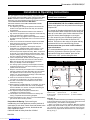
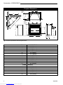
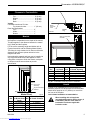
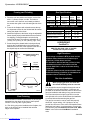
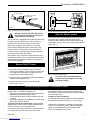
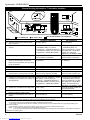
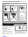
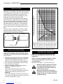
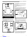
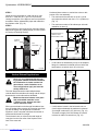
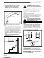
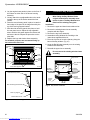
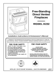
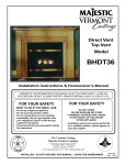
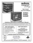
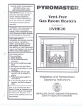
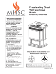
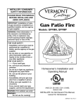
INSTALLER/CONSUMER
SAFETY INFORMATION
Builder Rear Vent
Direct Vent
PLEASE READ THIS MANUAL
BEFORE INSTALLING AND
USING APPLIANCE
Model: H33BDVRRN/P
WARNING!
IF THE INFORMATION IN THIS
MANUAL IS NOT FOLLOWED
EXACTLY, A FIRE OR EXPLOSION MAY RESULT CAUSING
PROPERTY DAMAGE, PERSONAL INJURY OR LOSS OF
LIFE.
FOR YOUR SAFETY
Installation and service must
be performed by a qualified
installer, service agency or the
gas supplier.
WHAT TO DO IF YOU SMELL
GAS:
• Do not try to light any appliance.
• Do not touch any electric switch;
do not use any phone in your
building.
• Extinguish all flames.
• Immediately call your gas
supplier from your neighbor's
phone. Follow the gas suppliers
instructions.
• If you cannot reach your gas
supplier call the fire department.
• Open windows/extinguish all
flames.
DO NOT STORE
OR USE GASOLINE OR
OTHER FLAMMABLE
VAPORS AND LIQUIDS IN
THE VICINITY OF THIS OR
ANY OTHER APPLIANCE.
Homeowner's Installation and
Operating Manual
DE S I GN
CFM Harris Systems
CE
RTIFI E D
C E RT I F I E D
3501 West Howard • Skokie, IL 60076 • 847-676-3556
www.cfmharris.com
INSTALLER: DO NOT DISCARD THIS MANUAL - LEAVE FOR HOMEOWNER
10004798 11/02 Rev. 0
Downloaded from www.Manualslib.com manuals search engine
Pyromaster© H33BDVRRN/P
Table of Contents
Please read the installation & operating instructions before using appliance
Thank you and congratulations on your purchase of a CFM Harris Systems fireplace.
IMPORTANT: Read all instructions and warnings carefully before starting installation.
Failure to follow these instructions fully may result in a possible fire hazard and will void the warranty.
Installation & Operating Instructions ........................................................................................... 3
Locating Your Fireplace .................................................................................................... 3
Fireplace Dimensions ......................................................................................................... 4
Clearance to Combustibles ................................................................................................ 5
Mantels .............................................................................................................................. 5
Hearth .............................................................................................................................. 5
Framing & Finishing ........................................................................................................... 6
Final Finishing .................................................................................................................... 6
Gas Specifications ............................................................................................................. 6
Gas Inlet and Manifold Pressures.................................................................................... .. 6
High Elevations .................................................................................................................. 6
Gas Line Installation ........................................................................................................... 6
Remote ON/OFF Switch .................................................................................................... 7
Alternate Switch Location ................................................................................................... 7
Venting Installation Instructions
General Venting Information-Termination Location ........................................................... 7
General Information on Assembling DV Components ....................................................... 9
Crimped End Pipes ............................................................................................................ 9
Twist Lock Pipes .............................................................................................................. 10
How to Use the Vent Graph...................................... ....................................................... 10
Rear Wall Vent Applications & Installation ....................................................................... 10
Vertical Sidewall Applications & Installation ..................................................................... 12
Below Grade Installations.. .............................................................................................. 15
Vertical Through-the-Roof Applications & Installation ...................................................... 16
Twist Lock Venting Components ...................................................................................... 18
Crimped End Venting Components .................................................................................. 19
Operating Instructions
Glass Information ............................................................................................................. 20
Louvre Removal ............................................................................................................... 20
Window Frame Assembly Removal ................................................................................. 20
Glass Cleaning ................................................................................................................. 20
Installation of Logs, Lava Rock & Ember Material ........................................................... 20
Flame & Temperature Adjustment ................................................................................... 21
Flame Characteristics ...................................................................................................... 21
Lighting Instructions ......................................................................................................... 22
Trouble Shooting .............................................................................................................. 24
Fuel Conversion Instructions ............................................................................................ 25
Maintenance
............................................................................................................................ 25
Replacement Parts ....................................................................................................................... 26
Optional Accessories
Fan Kits ............................................................................................................................ 28
Wiring Instructions ............................................................................................................ 29
EB-1 Electrical Box .......................................................................................................... 29
Ceramic Refractory Kits ................................................................................................... 29
Decorative Bay Windows ................................................................................................. 30
Bay Window Screen ......................................................................................................... 31
Remote Controls .............................................................................................................. 31
Trim Kit ............................................................................................................................. 31
2
Downloaded from www.Manualslib.com manuals search engine
10004798
Pyromaster© H33BDVRRN/P
Installation & Operating Instructions
This gas appliance should be installed by a qualified installer
in accordance with local building codes and with current CSAB149.1 Installation codes for Gas Burning Appliances and
Equipment. For USA Installations follow local codes and/or the
current National Fuel Gas Code. ANSI Z223.1.
FOR SAFE INSTALLATION AND OPERATION PLEASE
NOTE THE FOLLOWING:
1 . This fireplace gives off high temperatures and should be
located out of high traffic areas and away from furniture
and draperies.
2. Children and adults should be alerted to the hazards of
high surface temperatures of this fireplace and should stay
away to avoid burns or ignition of clothing.
3. CAUTION: Due to high glass surface temperature children
should be carefully supervised when in the same room as
fireplace.
4. Under no circumstances should this fireplace be modified.
Parts removed for servicing should be replaced prior to
operating this fireplace again.
5. Installation and any repairs to this fireplace must be
performed by a qualified installer, service agency or gas
supplier. A professional service person should be contacted to inspect this fireplace annually. Make it a practice
to have all of your gas fireplaces checked annually. More
frequent cleaning may be required due to excess lint and
dust from carpeting, bedding material, etc.
6. Control compartments, burners and air passages in this
fireplace should be kept clean and free of dust and lint.
Make sure the gas valve and pilot light are turned off
before you attempt to clean this fireplace.
7. The venting system (chimney) of this fireplace should be
checked at least once a year and if needed your venting
system should be cleaned.
8. Keep the area around your fireplace clear of combustible
materials, gasoline and other flammable vapor and liquids.
This fireplace should not be used as a drying rack for
clothing, nor should Christmas stockings or decorations be
hung on or around the fireplace.
9. Under no circumstances should any solid fuels (wood,
coal, paper or cardboard etc.) be used in this fireplace.
10.The flow of combustion and ventilation air must not be
obstructed in any way.
11.When fireplace is installed directly on carpeting, vinyl tile or
any combustible material other than wood, the fireplace
must be installed on a metal or wood panel extending the
full width and depth of the fireplace.
12.This fireplace requires adequate ventilation and
combustion air to operate properly.
13. This fireplace must not be connected to a chimney flue
serving a separate solid fuel burning fireplace.
14. When the fireplace is not in use it is recommended that the
gas valve be left in the OFF position.
Proposition 65 Warning: Fuels used in gas,
woodburning or oil fired appliances, and the products of
combustion of such fuels, contain chemicals known to the
State of California to cause cancer, birth defects and
other reproductive harm.
California Health & Safety Code Sec. 25249.6
10004798
Downloaded from www.Manualslib.com manuals search engine
This appliance has been approved for after-market
mobile home installations
IMPORTANT:
PLEASE REVIEW THE FOLLOWING CAREFULLY
Remove any plastic from trim parts before turning the
fireplace ON.
It is normal for fireplaces fabricated of steel to give off
some expansion and/or contraction noises during the
start up or cool down cycle. Similar noises are found
with your furnace heat exchanger or car engine.
It is not unusual for your CFM Harris Systems gas
fireplace to give off some odor the first time it is
burned. This is due to the curing of the paint and any
undetected oil from the manufacturing process.
Please ensure that your room is well ventilated
open all windows.
It is recommended that you burn your fireplace for at
least ten (10) hours the first time you use it. If the
optional fan kit has been installed, place the fan
switch in the “OFF” position during this time.
Locating Your Fireplace
A
E
B
Y
X
C
D
Y
X
B
F
LU584-1
Fig. 1 Locating Gas Fireplace.
A) Flat on wall
D)*Room divider
Y) 6" minimum
B) Cross corner
E) *Flat on wall corner
C) **Island
F) Chase installation
Note (Fig. 1):
** Island (C) and Room Divider (D) installation is possible as long
as the horizontal portion of the vent system (X) does not exceed
20 feet (610cm). See details in Venting Section.
* When you install your Vermont Castings, Majestic Products
fireplace in(D) Room divider or (E) Flat on wall corner positions
(Y), a minimum of 6 inches (153mm) clearance must be maintained from the perpendicular wall and the front of the fireplace.
See (Y) in Fig. 1.
3
Pyromaster© H33BDVRRN/P
Fireplace Dimensions
Rough
Opening
Depth
E
M
P
F
M
Q - Rough Opening Width
O
Rough
Opening
Height
N
G
I
R
B
D
C
H
A
J
K
L
4758
Fig. 2 Fireplace specifications and framing dimensions.
Ref.
H33BDVRRN/P
A
33” (838mm)
B
28⁷⁄₈” (733mm)
C
16³⁄₈” (416mm)
D
31” (787mm)
E
22” (559mm)
F
11¹⁄₂” (292mm)
G
14” (355mm)
H
20¹⁄₄” (515mm)
I
24¹⁄₂” (622mm)
J
5” (127mm)
K
7¹⁄₂” (297mm)
L
8¹⁄₂” (216mm)
Framing Dimensions
M
36” (914mm)
N
51” (1294mm)
O
25¹⁄₂” (648mm)
P
12” (305mm)
Q
33¹⁄₂” (851mm)
R
29” (737mm)
4
Downloaded from www.Manualslib.com manuals search engine
10004798
Pyromaster© H33BDVRRN/P
Clearance to Combustibles
Appliance
Top.............................................. 0” (0 mm)
Bottom........................................ 0” (0 mm)
Side............................................ 0” (0 mm)
Back........................................... 0” (0 mm)
Venting
Concentric sections of DV Vent
Top, bottom & sides.................. 1” (25 mm)
Rear Vent Applications:
Top............................................ 2”
Sides......................................... 1”
Bottom...................................... 1”
J
Black
Surround
Face
CFM164a
I
H
F
Mantel
Leg
K
L
Mantels
Side of Combustion
Chamber
The height that a combustible mantel is fitted above
the fireplace is dependent on the depth of the mantel.
This also applies to the distance between the mantel
leg (if fitted) and the fireplace.
For the correct mounting height and widths refer to
Figures 3a and 3b, and the following Mantel Charts.
The fitting of a bay window trim kit does not effect the
distances and reference points referred to in the
diagram and chart.
Noncombustible mantels and legs may be installed at
any height and width around the appliance. When
using paint or lacquer to finish the mantel, such paint
or lacquer must be heat resistant to prevent
discoloration.
M
N
O
CFM170
V
W
X
Ref.
Mantel
Leg Depth
Ref.
Mantel Leg from Side
of Comb. Opening
Y
F
G
H
I
J
10” (254mm)
8” 9203mm)
6” (152mm)
4” (101mm)
2” (50mm)
K
L
M
N
O
11¹⁄₂” (292mm)
9¹⁄₂” (241mm)
7¹⁄₂” (191mm)
5¹⁄₂” (140mm)
3¹⁄₂’” (89mm)
Z
A
B
C
D
G
E
Fig. 3b Combustible mantel leg minimum installation.
Fireplace
Top Louvre
Assembly
Top of Combustion
Chamber
Bottom of Door Triim
Mantel Chart
Ref.
V
W
X
Y
Z
CFM146
Mantel Shelf
Mantel from Top
or Breast Plate Ref. of Comb. Chamber
Depth
10” (254mm)
8” (203mm)
6” (152mm)
4” (101mm)
2” (50mm)
A
B
C
D
E
17” (432mm)
15” (381mm)
13” (330mm)
11” (279mm)
9” (229mm)
Hearth
A hearth is not mandatory but is recommended for
aesthetic purposes. We recommend a noncombustible
hearth which projects out 12” (305mm) or more from
the front of the fireplace.
Cold climate installation recommendation:
When installing this unit against a
noncombustible exterior wall or chase, it
is mandatory that the outer walls be
insulated to conform to applicable
insulation codes.
Fig. 3a Combustible mantel minimum installation.
10004798
Downloaded from www.Manualslib.com manuals search engine
5
Pyromaster© H33BDVRRN/P
Framing and Finishing
Gas Specifications
1. Choose the unit location.
2. Place the unit into position and secure it to the floor
with 1¹⁄₂” (38mm) screws, or nails. The holes to
secure the unit to the floor are located just behind
the access door grille on the left and right side of the
unit.
3. Frame in the fireplace with a header across the top.
It is important to allow for the finished wall face when
setting the depth of the frame.
4. Attach the fireplace to the frame using the adjustable
frame drywall strips (located behind the access door
for shipping). Preset the depth to suit the facing
material of the wall. The strips are adjustable to 1/2”
(13mm), 5/8” (16mm), or 3/4” (19mm). (Figs. 3 & 4)
5. Screw through the slotted holes in the drywall strip
and into the pre-drilled holes in the fireplace side.
Measure from the face of the fireplace to the face of
the drywall strip to confirm the final depth.
Model
Fuel
Gas Control
H33BDVRRN Nat
H33BDVRRP Prop
Millivolt
Millivolt
Max.
Input
BTU/h
15,000
15,000
Min.
Input
BTU/h
10,500
11,250
Gas Inlet and Manifold Pressures
Natural
LP (Propane)
Minimum Inlet Pressure
5.5” wc
11” wc
Maximum Inlet Pressure
14” wc
14” wc
Manifold Pressure
3.5” wc
10” wc
H33BDVRRN/P
Certified To
ANSI Z21.88b-1999 / CSA 2.33b-M99
Vented Gas Fireplace Heaters
C
B
Adjustable Drywall Strip
(Nailing Flange)
A
Screw
Position
A
B
C
Drywall
Depths
1/2” / 13mm
5/8” / 16mm
3/4” / 19mm
High Elevations
Input ratings are shown in BTU per hour and are
certified without deration for elevations up to
4,500 feet (1,370m) above sea level.
For elevations above 4,500 feet (1,370m) in USA,
installations must be in accordance with the
current ANSI Z223.1 and/or local codes having
jurisdiction.
In Canada, please consult provincial and/or local
authorities having jurisdiction for installations at
elevations above 4,500 feet (1,370m).
Gas Line Installation
When purging gas lines, the front window frame assembly must be removed.
Adjustable 1/2”,
5/8” & 3/4”
Spacing
FP1023
Fig. 4 Adjustable drywall strip (nailing flange).
Final Finishing
Noncombustible materials such as brick or tile may be
extended over the edges of the face of the fireplace.
DO NOT cover any vent or grille panels.
If a Trim Kit is going to be installed on the fireplace, the
brick or tile will have to be installed flush with the
edges of the fireplace.
6
Downloaded from www.Manualslib.com manuals search engine
The gas pipeline can be brought in through the rear of
the appliance as well as the bottom. Knockouts are
provided on the bottom behind the valve to allow for the
gas pipe installation and testing of any gas connection.
It is most convenient to bring the gas line in from the
rear right side of the valve as this allows fan installation
or removal without disconnecting the gas line.
The gas line connection can be made with properly
tinned 3/8” copper tubing, 3/8” rigid pipe or an approved flex connector. Since some municipalities have
additional local codes, it is always best to consult your
local authority and the National Fuel Gas Code, ANSI
Z223.1 in the USA or the CSA-B149.1 installation
code.
10004798
Pyromaster© H33BDVRRN/P
Remote ON/OFF Switch
1/2” Gas Supply
TPTH
1/2” NPT x 1/2” Flare
Shut-Off Valve
3/8” Flex Line
(From Valve)
TP
TH
FP297a
FP1218
Fig. 5 Typical gas supply installation.
Always check for gas leaks with a mild
soap and water solution. Do not use an
open flame for leak testing.
The gas control is equipped with a captured screw type
pressure test point, therefore it is not necessary to
provide a 1/8" test point up stream of the control.
When using copper or flex connector use only approved fittings. Always provide a union when using
black iron pipe so the gas line can be easily disconnected for burner or fan servicing. See gas specification for pressure details and ratings.
Fig. 6 Remote switch wiring diagram.
Alternate Switch Location
The remote switch can be installed on the front/side of
the access door. Simply mount the switch to the
bracket provided and screw the bracket to either side
of the frame, lining up the screws with the pre-punched
holes. (Fig. 7)
The fireplace valve must not be subjected to any test
pressures exceeding 1/2 psi. Isolate or disconnect this
and any other gas appliance control from the gas line
when pressure testing.
Remote ON/OFF Switch
Installation
1. Thread the wiring through the holes on the end
panels of the fireplace. Take care not to cut the wire
or insulation on metal edges. Route the wire to a
conveniently located receptacle box.
2. Attach the wire to the ON/OFF switch and install the
switch into the receptacle box.
3. Connect the other ends of the wire to the gas
control valve. (Fig. 6)
Fig. 7 Alternate switch location.
Do not wire the remote ON/OFF wall
switch for the gas fireplace to the 120
volt power supply.
General Venting Information–Termination Location
Your fireplace is approved to be vented either through
the side wall, or vertically through the roof.
• Only venting components specifically approved and
labelled for this fireplace may be used.
• Vent terminations shall not be recessed into a wall
or siding.
• Horizontal venting must be installed on a level plane
without any incline or decline.
There must not be any obstruction such as bushes,
garden sheds, fences, decks or utility buildings within
24" from the front of the termination hood.
Do not locate termination hood where excessive snow
or ice build up may occur. Be sure to check vent
10004798
Downloaded from www.Manualslib.com manuals search engine
termination area after snow falls, and clear to prevent
accidental blockage of venting system. When using
snow blowers, make sure snow is not directed towards
vent termination area.
Location of Vent Termination
It is imperative the vent termination be located observing
the minimum clearances as shown on the next page.
*Check with local codes or in absence of same with
CSA-B149.1 Installation Codes (1991) for Canada or
follow the current National Fuel Gas Code, ANSI
Z223.1 for installations in the USA.
7
Pyromaster© H33BDVRRN/P
General Venting Information - Termination Location
INSIDE
CORNER DETAIL
G
V
H
A
D
V
N
N
E
V
B
C
V
L
B
Fixed
Closed
Ope
F
B
V
Operable
rab
V
le
V
Fixed
Closed
G
V
B
B
B
V
J
X
I
A
V VENT TERMINATION
M
G
V
K
X
V
A
X AIR SUPPLY INLET
AREA WHERE TERMINAL IS NOT PERMITTED
CFM145a
Canadian Installations1
A = Clearance above grade, veranda, porch,
deck, or balcony
B = Clearance to window or door that may be
opened
C = Clearance to permanently closed window
D = Vertical clearance to ventilated soffit located
above the terminal within a horizontal
distance of 2 feet (610mm) from the center
line of the terminal
E = Clearance to unventilated soffit
F = Clearance to outside corner
G = Clearance to inside corner (see next page)
H = Clearance to each inside of center line
extended above meter/regulator assembly
I = Clearance to service regulator vent outlet
J = Clearance to nonmechanical air supply inlet
to building or the combustion air inlet to any
other appliances
K = Clearance to a mechanical air supply inlet
US Installations2
12 inches (30cm)
12 inches (30cm)
6 in (15cm) for appliances
< 10,000Btuh (3kW), 12 in (30cm)
for appliances > 10,000 Btuh (3kW) and
< 100,000 Btuh (30kW), 36 inches (91cm)
for appliances > 100,000 Btuh (30kW)
12” (305mm) recommended to
prevent window condensation
6 in (15cm) for appliances
< 10,000 Btuh (3kW), 9 in
(23cm) for appliances > 10,000
Btuh (3kW) and < 50,000 Btuh
(15kW), 12 in (30cm) for
appliances > 50,000 Btuh (15kW)
12” (305mm) recommended to
prevent window condensation
18” (458mm)
18” (458mm)
12” (305mm)
see next page
see next page
3 feet (91cm) within a height of 15 feet
above the meter/regulator assembly
3 feet (91cm)
6 inches (15cm) for appliances < 10,000
Btuh (3kW), 12 inches (30cm) for
appliances > 10,000 Btuh (3kW) and <
100,000 Btuh (30kW), 36 inches (91cm)
for appliances > 100,000 Btuh (30kW)
12” (305mm)
see next page
see next page
3 ft (91cm) within a height of 15ft
above the meter/regulator assy
3 feet (91cm)
6 inches (15cm) for appliances
< 10,000 Btuh (3kW), 9 inches
(23cm) for appliances > 10,000
Btuh (3kW) and < 50,000 Btuh
(15kW), 12 inches (30cm) for
appliances > 50,000 Btuh (15kW)
3 feet (91cm) above if within 10
feet (3m) horizontally
7 feet (2.13m)†
6 feet (1.83m)
L = Clearance above paved sidewalk or paved 7 feet (2.13m)†
driveway located on public property
M = Clearance under veranda, porch, deck or
12 inches (30cm)c
12 inches (30cm)†
balcony
N = Clearance above a roof shall extend a minimum of 24” (610mm) above the highest point when it passes through the roof
surface, and any other obstruction within a horizontal distance of 18” (450mm).
1 In accordance with the current CSA-B149 Installation Codes
2 In accordance with the current ANSI Z223.1/NFPA 54 National Fuel Gas Codes
† A vent shall not terminate directly above a sidewalk or paved driveway which is located between two single family dwellings and
serves both dwellings
‡ only permitted if veranda, porch, deck or balcony is fully open on a minimum 2 sides beneath the floor:
NOTE: 1. Local codes or regulations may require different clearances.
2. The special venting system used on CFM Harris Fireplaces are certified as part of the appliance, with clearances tested and
approved by the listing agency.
8
Downloaded from www.Manualslib.com manuals search engine
10004798
Pyromaster© H33BDVRRN/P
Termination Clearances
Termination clearances for buildings with combustible and noncombustible exteriors.
Inside Corner
Recessed Location
Outside Corner
A=
Combustible
6"(152mm)
Noncombustible
2"(50mm)
A
V
B=
Combustible
6"(152mm)
Noncombustible
2"(50mm)
V
D
C
C
E
V
B
Balcony with perpendicular side wall
Balcony with no side wall
G
V
V
G=
Combustible&
Noncombustible
12"(305mm)
C = Maximum depth of 48"
(1219mm) for recessed
location.
H
Combustible &
Noncombustible
D = Minimum width for back wall
of a recessed location.
Combustible 38"(965mm)
Noncombustible 24"(610mm)
J
E = Clearance from corner in
recessed location.
Combustible 6"(152mm)
Noncombustible 2"(50mm)
H = 24"(610mm)
J = 20"(508mm)
584-15
Fig. 8 Termination clearances.
General Information on Assembling DV Components
Crimped End Pipes
Before joining elbows and pipes apply a bead of high
temperature sealant to the crimped end of the elbow or
pipe. Join the pipes using a 2” (50mm) overlap and
secure the joints with three sheet metal screws. (Fig. 9)
Wipe off excess sealant.
Sealant
1" (25mm)
Canadian Installations:
Venting system must be installed in accordance with
the current CSA-B149.1 installation code.
USA Installations:
The venting system must conform with local codes
and/or the current National Fuel Gas code ANSI
Z223.1.
Only venting components manufactured by CFM
Corporation can be used in Direct Vent systems.
10004798
Downloaded from www.Manualslib.com manuals search engine
Screw Holes
FP1175
Fig. 9 Apply a bead of high temperature sealant.
It is possible to use CFM Corporation 4” & 7” direct vent
crimped pipe and elbows with CFM Corporation 4” & 7”
twist-lock pipe. NOTE: The crimped pipe must be
used first.
9
Pyromaster© H33BDVRRN/P
Twist Lock Pipes
To join the twist lock pipes together, simply align the
beads of the male end with the grooves of the female
end, then while bringing the pipe together, twist the
pipe until the flange on the female end contacts the
external flange on the male end. It is recommended
that you secure the joints with three (3) sheet metal
screws, however this is not mandatory with twist lock
pipe.
To make it easier to assemble the joints we suggest
putting a lubricant (Vaseline or similar) on the male
end of the twist lock pipe prior to assembly.
Male End
Female End
30
29
28
27
26
25
Vertical Dimension from the Floor of the Unit to
the Center of the Horizontal Vent Pipe
When using CFM Corporation twist-lock pipe it is not
necessary to use sealant on the joints. The only areas
of the venting system that need to be sealed with high
temperature silicone sealant are the collars on the
fireplace and termination, and the sliding joint of any
telescopic vent section used in the system.
24
23
22
21
20
19
18
17
16
15
14
13
12
eg: A
11
10
9
8
7
eg: B
6
5
4
3
3
Screw Holes
TWL100
How to Use the Vent Graph
The vent chart should be read in conjunction with the
following vent installation instructions to determine the
relationship of the vertical and horizontal dimensions of
the vent system.
1. Determine the height of the center of the horizontal
vent pipe exiting through the outer wall. Using this
dimension on the Sidewall Vent Graph. (Fig. 11)
locate the point intersecting with slanted graph line.
2. From the point of this intersection, draw a vertical
line to the bottom of the graph.
3. Select the indicated dimension, and position the
fireplace in accordance with same.
Example A:
If the vertical dimension from the floor of the
fireplace is 11’ (3.4m) the horizontal run to the face
of the outer wall must not exceed 14’ (4.3m).
Example B:
If the vertical dimension from the floor of the unit is
7’ (2.14m), the horizontal run to the face of the outer
wall must not exceed 8¹⁄₂’ (2.6m).
Downloaded from www.Manualslib.com manuals search engine
5 6 7
8 9 10 11 12 13 14 15 16 17 18 19 20
Horizontal Dimension From The Outside Face Of The
Wall To The Center Of The Fireplace Vent Flange
Fig. 10 Twist-lock pipe joints.
10
4
Sidewall vent graph showing the relationship between vertical
and horizontal dimensions for a Direct Vent flue system.
Fig. 11 Sidewall venting graph. (Dimensions in feet)
Rear Wall Vent Applications
NOTE: It is not necessary to seal the vent pipe
joints for any straight out of the wall rear vent
applications.
NOTE: Vent Starter Kit Model 7TDVSK or 7DVSK
must be used in straight out of the wall rear
vent applications.
Maximum Vent Length......20” (508 mm) (Fig. 12)
Minimum clearance between vent pipes
and combustible materials is one (1”)
inch (25 mm) on the sides and two (2”)
inches (50 mm) on top.
When vent termination exits through
foundation less than 20” (508 mm) below
siding outcrop, the vent pipe must flush
up with the siding.
10004798
Pyromaster© H33BDVRRN/P
Top View
Straight Venting
20" (508mm)
Max.
Combustible Walls: Cut a 10³⁄₈”H (264 mm) x 9³⁄₈” W
(240 mm) hole through the exterior wall and frame as
shown. (Fig.13)
Noncombustible Walls: Hole opening must be 7¹⁄₂”
(190 mm) in diameter. (Fig. 13)
STEP 2
20"
(508mm)
Max.
Measure wall thickness and cut zero clearance sleeve
parts to proper length (MAXIMUM 12”/305 mm).
Assemble sleeve and attach to firestop with #8 sheet
metal screws (supplied).
20"
(508mm)
Max.
Max. Length
12” (294mm)
Adjustable Zero
Clearance Sleeve
45 ¡
45 ¡
Top View Cross Corner Vent
to the Left
Top View Cross Corner Vent
to the Right
#8 Screws
(2)
#8 Screws
(2)
Adjustable
Zero
Clearance
Sleeve
H8
Screws
Fig. 12 Rear vent applications.
Firestop
Rear Wall Installations
ZCS101
Fig. 14 Adjustable zero clearance sleeve.
STEP 1
Locate vent opening on the wall. To locate hole center
consult with appropriate fireplace dimensions, Page 4.
Frame as shown below.
Vent Opening for Combustible Wall
9³⁄₈”
(240mm)
STEP 3
Measure from the fireplace collar or elbow face to face
of outside wall (add 2” for vent pipe overlap). Mark
pipes and cut to length. It is very important that the two
pipes are flush with the outside wall once the fireplace
is in its final location.
Zero
Clearance
Sleeve
10³⁄₈”
(254mm)
Firestop
Framing Detail
Vent Opening for Noncombustible Wall
CFM133
7¹⁄₂”
(190mm)
Fig. 15 Zero clearance sleeve and firestop installation.
STEP 4
VO584-100
Fig. 13 Straight out through the wall application.
10004798
Downloaded from www.Manualslib.com manuals search engine
Slip 4” and 7” pipes onto respective flue collars. Make
sure to fix to the fireplace collar the 4” pipe with three
(3) screws before fixing the 7” pipe on the 7” collar.
Both pipes must be on a level plane. (Fig 16)
11
Pyromaster© H33BDVRRN/P
STEP 5
Guide the vent termination 4” collar into the 4” pipe
then the 7” collar into the 7” pipe. Do not force the
venting into position. If the pipes do not line up with the
termination collars, disassemble pipes and reattach to
the fireplace collar. (Fig. 16)
STEP 6
Horizontal plane means no vertical rise exists on this
portion of the vent assembly.
• The maximum horizontal vent run is 20 ft. (6100
mm) when the vertical vent rise is 7¹⁄₂ ft. (2286 mm).
(Fig. 17)
• The maximum number of 90° elbows per side wall
installation is three (3).
Secure fireplace to floor through floor holes and adjustable frame drywall strip (nailing flange) to frame. (Refer
to Framing & Finishing Section).
Maximum
20 ft. (6100mm)
Vertical Dimension 7¹⁄₂
ft. Minimum when
Horizontal Run is 20 ft.
48"
(1220mm)
12"
(305mm)
15 ft.
(4572mm)
Finished
Wall
Vent
Termination
90"
(2286mm)
7TDVRT90
Elbow
Fig. 17 Maximum dimensions.
• If a 90° elbow is fitted directly on top of the fireplace
FP1005b
Fig. 16 Side view of final unit location.
flange, the maximum horizontal vent run before the
termination or a vertical rise is 36" (914 mm).
Maximum
3’ (914mm)
Vertical Sidewall Applications
Since it is very important that the venting system maintain its balance between
the combustion air intake and the flue
gas exhaust, certain limitations as to
vent configurations apply and must be
strictly adhered to.
The Vent Graph shows the relationship between
vertical and horizontal side wall venting and will help to
determine the various dimensions allowable.
Minimum clearance between vent pipes
and combustible materials is one
1"(25mm) on top, bottom and sides
unless otherwise noted.
When vent termination exits through foundations less
than 20" below siding outcrop, the vent pipe must flush
up with the siding. It is always best to locate the
fireplace in such a way that minimizes the number of
offsets and horizontal vent length.
7TDVRT90
Elbow
Side View
CFM142
Fig. 18 Maximum horizontal vent run before termination.
• If a 90° elbow is used in the horizontal vent run
(level height maintained) the maximum horizontal
vent length is reduced by 36" (914 mm). (Fig. 18)
This does not apply if the 90° elbows are used to
increase or redirect a vertical rise. (Fig. 19)
The horizontal vent run refers to the total length of
vent pipe from the flue collar of the fireplace to the
face of the outer wall.
12
Downloaded from www.Manualslib.com manuals search engine
10004798
Pyromaster© H33BDVRRN/P
Example: According to the chart the maximum
horizontal vent length in a system with a 7.5'
vertical rise is 20' (6 m) and if a 90° elbow is
required in the horizontal vent it must be reduced to
17' (5.2 m). In Figure 20 Dimension A plus B must
not be greater than 17' (5.2 m).
7 ft.
(2134 mm)
A
B
10 ft.
(3048 mm)
• IMPORTANT • Minimum clearance between vent pipes and combustible materials
is one (1”) inch (25 mm) on bottom, sides
and top.
Twist Lock Vent Starter Kit 7DVSK, plus Transition
Elbow 7DVRT90 must be used in Vertical Sidewall
installations. The 4” pipe must be centred inside
the 7” pipe coming off the 7DVRT90 transition
elbow.
Canadian & USA Installations:
90ß elbow = 3 ft.
The venting system must conform with local codes, or
in the absence of local codes, with National Fuel Gas
Code, ANSI Z223.1 - latest edition, or CSA-B149.1
Installation Code.
A + B = 17 ft. (Max.)
7 ft. 6 in.
(2286 mm)
Only CFM Corporation venting components specifically approved and labelled
for this fireplace may be used.
Vertical Sidewall Installations
CFM147
STEP 1
Fig. 19 Dimension A plus B must not be greater than 17’
(5.2m).
• The maximum number of 45° elbows permitted per
side wall installation is two (2). These elbows can
be installed in either the vertical or horizontal run.
• For each 45° elbow installed in the horizontal run,
Locate vent opening on the wall. It may be necessary
to first position the fireplace and measure to obtain
hole location. Depending on whether the wall is combustible or noncombustible, cut opening to size. (Fig.
21)
(For combustible walls first frame in opening.)
Vent Opening for Combustible Wall
the length of the horizontal run MUST be reduced
by 18" (45cm). This does not apply if the 45°
elbows are installed on the vertical part of the vent
system.
• The maximum number of elbow degrees in a
system is 270°. (Fig. 20)
9³⁄₈”
(240mm)
9³⁄₈”
(240mm)
Example:
Elbow 1
Elbow 2
Elbow 3
Elbow 4
Total angular variation
=
=
=
=
=
90°
45°
45°
90°
270°
Framing Detail
4
Vent Opening for Noncombustible Wall
7¹⁄₂”
(190mm)
1 + 2 + 3 + 4 = 270°
3
VO584-100
2
1
Fig. 21 Locate vent opening on wall.
Combustible Walls (Fig. 21): Cut a 9³⁄₈”H x 9³⁄₈” W
(240 mm x 240 mm) hole through the exterior wall and
frame.
CFM132
Noncombustible Walls (Fig. 21): Hole opening must
be 7¹⁄₂” (190 mm) in diameter.
Fig. 20 Maximum elbow usage.
10004798
Downloaded from www.Manualslib.com manuals search engine
13
Pyromaster© H33BDVRRN/P
STEP 2
STEP 4
Measure wall thickness and cut adjustable zero clearance sleeve parts to proper length (MAXIMUM 12”/305
mm). (Fig. 22) Adjust sleeve to minimum (9³⁄₈” x 9³⁄₈”)
and attach to firestop with #8 sheet metal screws
(supplied). Assemble sleeve and attach to firestop with
#8 sheet metal screws (supplied). Install firestop
assembly.
Measure the horizontal length requirement including a
2” (50 mm) overlap, i.e. from the elbow to the outside
wall finish plus 2” (or the distance required if installing
a second 90° elbow. (Fig. 24)
Always install horizontal venting on a
level plane.
Zero clearance sleeve is only required
for combustible walls.
X
Maximum Length
12” (294mm)
Adjustable Zero
Clearance Sleeve
#8 Screws (2)
#8 Screws
(2)
Adjustable
Zero
Clearance
Sleeve
#8 Screws
Wall Exterior
Wood
Framing
Firestop
Firestop
Zero Clearance
Sleeve Flush with
Wall Exterior
CFM136
Vent Pipe
Drywall
CFM135
Fig. 24 Measure horizontal length requirement plus 2”.
STEP 5
Fig. 22 Zero clearance sleeve and firestop.
STEP 3
Apply a bead of high temperature sealant to the inner
and outer flue collars of the fireplace and using appropriate venting component(s) attach to fireplace with
three (3) screws. (Fig. 23) Follow with the installation
of the inner and outer elbow. Again secure joints with
three (3) sheet metal screws. Wipe off any excess high
temperature sealant.
Use appropriate length of pipe section - telescopic or
fixed - and install the horizontal vent sections. The 20”
(508 mm) section of pipe which goes through the wall
is packaged with the 7DVSK starter kit, and can be cut
to suit if necessary. (Fig. 25)
Sealing vent pipe and firestop gaps with
high temperature sealant will restrict
cold air being drawn in around fireplace.
High Temperature
Sealant
X
Ensure
Pipes are
Concentric
X
7TDVRT90
Bead
of Sealant
(If necessary)
CFM137
CFM143
Fig. 23 Apply bead of sealant as needed.
14
Downloaded from www.Manualslib.com manuals search engine
Fig. 25 Install horizontal vent sections.
10004798
Pyromaster© H33BDVRRN/P
STEP 6
Apply high temperature sealant to 4” (100 mm) and 7”
(175 mm) collars or the termination one inch away from
the crimped end. Guide the vent termination’s 4” and 7”
collars into their respective vent pipes. Double check
that the vent pipes overlap the collars by 2” (50mm).
Secure the termination to the wall with screws provided
and caulk around the wall plate to weatherproof. (Fig.
26)
X
X
The maximum horizontal run with 24”
vertical rise is 36” (914 mm) from the
back of the fireplace to the face of the
exterior wall. See vent graph (Page 11)
for extended horizontal run if the vertical
rise exceeds 24” (610mm).
1. Establish vent hole through the wall. (Fig. 21)
2. Remove soil to a depth of approximately 16"
(406mm) below base of snorkel. Install window well
(not supplied). Refill hole with 12" (305mm) of
coarse gravel leaving a clearance of approximately
4" (100mm) below snorkel. (Fig. 27)
3. Install vent system. Refer to Page 14, Steps 2
through 5.
4. Ensure a watertight seal is made around the vent
pipe coming through the wall.
5. Apply high temperature sealant caulking (supplied)
around the 4” and 7” 7DVSKS’s snorkel collars.
6. Slide into the vent pipe and secure to the wall.
7. Level the soil to maintain a 4" (100mm) clearance
below snorkel. (Fig. 27)
CFM138
Fig. 26 Install vent terminations.
STEP 7
Zero Clearance
Sleeve if Required
7DVSKS
(Snorkel)
Firestop
7” Pipe
Minimum 4”
Clearance
Ground
Window Well
Support the horizontal pipes every 36” (914mm) with
metal pipe straps. Make sure that the horizontal vent
pipe is installed on a level horizontal plane.
STEP 8
Re-check the fireplace to make sure that it is levelled,
properly positioned, and nailed or screwed to the floor.
If applied, the fireplaces adjustable frame drywall strips
(nailing flanges) should be fastened. Refer to “Framing
& Finishing”.
Below Grade Installations
When it is not possible to meet the required vent
terminal clearances of 12” (305mm) above grade level
a snorkel vent kit #7DVSKS is required. It allows
installation depth of down to 7” (178mm) below grade
level. The 7” is measured from the center of the
horizontal vent pipe as it penetrates through the wall.
If venting system is installed below
ground, we recommend a window well
with adequate and proper drainage.
Gravel
24”
(608mm)
Minimum*
Drain
Foundation Wall
*A minimum of 24”
(608mm) vertical pipe
must be installed when
using the 7DVSKS kit.
FP1220
Fig. 27 Below grade installation.
Do not back fill around snorkel. A
clearance of at least 4” (100mm) must be
maintained between the snorkel and the
soil.
Ensure sidewall venting clearances are observed.
10004798
Downloaded from www.Manualslib.com manuals search engine
15
Pyromaster© H33BDVRRN/P
If the foundation is recessed, use recess brackets (not
supplied) for securing lower portion of the snorkel.
Fasten brackets to wall first, then secure to snorkel
with self drilling #8 x 1/2 sheet metal screws. It will be
necessary to extend vent pipes out as far as protruding
wall face. (Fig. 28)
Example: Maximum horizontal length
0 x 45° elbows = 10’ (3048mm)
1 x 45° elbows = 8¹⁄₂’ (2590mm)
2 x 45° elbows = 7’ (2133mm)
c. A minimum of an 8’ vertical rise.
d. Two sets of 45° elbows offsets within these vertical
installations. From 0 to a maximum of 8’ (2438 mm)
of vent pipe can be used between elbows. (Fig. 30)
Snorkel
Foundation Recess
Wall Screws
e. 7DVCS must be used to support offsets. (Fig. 32)
This application will require that you first determine
the roof pitch and use the appropriate 7DVSKV (A,
B or F). (Refer to Venting Components List, pages
18, 19)
Recess Brackets
Sheet Metal
Screws
Watertight Seal
Around Pipe
Max.
8 Feet
(2438mm)
CFM139
Fig. 28 Snorkel installation, recessed foundation.
45°
Vertical Through-the-Roof Applications
This Gas Fireplace has been approved for:
a. Vertical installations up to 40’ (12m) in height. Up to
10’ (3048mm) horizontal vent run can be installed
within the vent system using a maximum of three
90° elbows.
Minimum
8ft. /
Maximum
40 ft. Vertical
Rise
40 Feet
(12.2m)
Max.
8 Feet
(2438mm)
45°
Maximum
10ft.
(3048mm)
CFM140
Fig. 30 Typical straight-up installation.
Vertical Through-the-Roof Installation
Pipe Straps
Every 3’
(914mm)
CFM148
Fig. 29 Vertical through-the-roof application.
b. Up to two 45° elbows may be used within the
horizontal run. For each 45° elbow used on the
horizontal level the maximum horizontal length must
be reduced by 18” (457mm).
16
Downloaded from www.Manualslib.com manuals search engine
1. Locate your fireplace.
2. Plumb to center of the (4”) flue collar from ceiling
above and mark position.
3. Cut opening equal to 9³⁄₈” x 9³⁄₈” (240 mm x 240 mm).
4. Proceed to plumb for additional openings through
the roof. In all cases, the opening must provide a
minimum of 1 inch clearance to the vent pipe,
i.e.,the hole must be at least 9³⁄₈” x 9³⁄₈” (240 mm x
240 mm).
5. Place fireplace into position.
10004798
Pyromaster© H33BDVRRN/P
6. Place firestop(s) #7DVFS or Attic Insulation Shield
#7DVAIS into position and secure. (Fig. 31)
7. Install roof support (Fig. 32) and roof flashing
making sure upper flange is below the shingles.
(Fig. 33)
8. Install appropriate pipe sections until the venting is
above the flashing. (Fig. 33)
9. Install storm collar and seal around the pipe.
10. Add additional vent lengths for proper height. (Fig
34)
11. Apply high temperature sealant to 4” and 7” collars
of vertical vent termination and install.
Typical Roof
Support Application
Typcal Ceiling
Support Application
FP1184
Fig. 32 Typical support applications.
Attic
Insulation
Shield
#5 Sheet Metal
Screws
(3 per joint)
Joist
Sealant
Storm
Collar
#5 Sheet
Metal
Screws
(3 per joint)
Sealant
Storm
Collar
TWL101a
11"
11"
Fig. 33 Roof flashing.
Upper Floor
Ceiling
Installation
Joist
Min.
2’ (610 mm)
Firestop Spacer
Nails (4)
CFM100
Fig. 31 Place firestop spacer(s) and secure.
If there is room above ceiling level,
firestop spacer must be installed on both
the bottom and the top side of the ceiling
joists. If an attic is above ceiling level a
7DVAIS (Attic Insulation Shield) must be
installed. (Fig. 31)
CFM190
Fig. 34 Minimum termination to roof clearance.
The enlarged ends of the vent section
always face downward. (Fig. 33)
10004798
Downloaded from www.Manualslib.com manuals search engine
17
Pyromaster© H33BDVRRN/P
Twist Lock Venting Components
7TDVRVT-Through the wall Rear Vent Termination
Starter Kit-Model7TDVSK-Sidewall Venting
Starter Kit-Model 7TDVSKV-Vertical Venting
for 7TDVSKV-A order 1/12 to 6/12 roof pitch
for 7TDVSKV-B order 7/12 to 12/12 roof pitch
for 7TDVSKV-F order flat roof
Starter Kit-Model 7DVSKS-Snorkel Kit
for Below Grade Installation
45° elbow kit
7TDV45 for Rear Vent to Vertical Vent or
Vertical/Horizontal Offsets
90° Transition elbow kit
7TDVRT90 for Rear Vent to Vertical Vent
90° Elbow
7TDV90 Vertical/Horizontal Offset
Telescopic vent sections 12” to 18”
7TDVP1218
-12” to 18” adjustable length
7TDVP3564
-35” to 64” adjustable length
Pipe sections for vertical or horizontal venting
Model 7TDVP8”
4 per box
Model 7TDVP12”
4 per box
Model 7TDVP24”
4 per box
Model 7TDVP36”
Model 7TDVP48”
Firestop Spacer
Model 7DVFS
Attic Insulation Shield
Model 7DVAIS
Vertical/Horizontal Combination Offset Support
Model 7DVCS
18
Downloaded from www.Manualslib.com manuals search engine
10004798
Pyromaster© H33BDVRRN/P
Crimped End Venting Components
7TDVRVT-Through the wall Rear Vent Termination
Starter Kit-Model 7TDVSK-Sidewall Venting
Starter Kit-Model 7TDVSKV-Vertical Venting
for 7TDVSKV-A order 1/12 to 6/12 roof pitch
for 7TDVSKV-B order 7/12 to 12/12 roof pitch
for 7TDVSKV-F order flat roof
Starter Kit-Model 7DVSKS-Snorkel Kit
for Below Grade Installation
45° elbow kit
7DVT45 for Vertical Installation Offsets
7DVR45 for Rear Vent Application
90° Transition elbow kit
7DVRT90 for Vertical Sidewall Applications
or through-the-roof.
Telescopic vent sections
7DVP610
-6” to 10” adjustable length
7DVP1018
-10” to 18” adjustable length
7DVP1834
-18” to 34” adjustable length
7DVP3466
-34” to 66” adjustable length
Pipe sections for vertical or horizontal venting
Model 7DVP8” 4 per box
Model 7DVP12” 4 per box
Model 7DVP24” 4 per box
Model 7DVP36”
Model 7DVP48”
Firestop Spacer
Model 7DVFS
Attic Insulation Shield
Model 7DVAIS
Vertical/Horizontal Combination Offset Support
Model 7DVCS
10004798
Downloaded from www.Manualslib.com manuals search engine
19
Pyromaster© H33BDVRRN/P
Operating Instructions
Glass Information
•
Only glass approved by the CFM
Corporation should be used on this
fireplace.
The use of any non-approved replacement glass will
void all product warranties.
• Care must be taken to avoid breakage of the glass.
• Under no circumstances should this appliance be
operated without the window frame assembly in
place, or with the glass in a damaged condition.
Lower
Clamps
Window
Frame
Assembly
Window
Frame
Assembly
• Replacement glass (complete with gasket) is
available through your CFM Harris dealer and
should only be installed by a licensed qualified
service person.
Push Clamp
Handle
FP771b
Fig. 36 Window frame assembly removal.
Louvre Removal
The top louvre panel is
removed by lifting the
panel vertically and pulling
it away from the appliance.
(Fig. 35) The lower access
door is hinged along the
bottom edge and is folded
down to allow access.
Pull Clamp
Hook
Glass Cleaning
2.
Louvre
1.
Glass Panel
FP1221
Fig. 35 Remove top louvre
panel.
Window Frame Assembly Removal
1. Turn the fireplace OFF (including the pilot).
2. If the unit has been operating allow time for the
components to cool.
3. Remove the top louvre assembly.
4. Open the lower louvre panel.
5. Release the two clamps securing the lower edge of
the window frame assembly by pulling down on the
handles. (Fig. 36)
6. Tilt the window frame assembly out slightly at the
bottom, lift the window frame assembly up and away
from the fireplace.
7. To replace the window frame assembly reverse the
procedure.
20
Downloaded from www.Manualslib.com manuals search engine
It is necessary to periodically clean glass. During startup condensation, which is normal, forms on the inside
of the glass. This condensation causes lint, dust and
other airborne particles to cling to glass surface.
Also initial paint curing may deposit a slight film on the
glass. It is therefore recommended the glass be
cleaned two or three times with a non-ammonia based
household cleaner and warm water (We recommend
gas fireplace glass cleaner) within the first few weeks
of operation.
After the initial cleaning process the glass should be
cleaned two or three times during each operating
season depending on the environment in the house.
Clean the glass after the first two weeks
of operation.
Installation of Logs,
Lava Rock & Ember Material
Unpack the logs from packaging and remove each log
from its wrapping materials.
The logs are fragile and should be
handled with care. Keep the packaging
material out of the reach of children and
dispose of the material in a safe manner.
The individual logs can be easily identified by the
numbers cast on the underside of each log.
10004798
Pyromaster© H33BDVRRN/P
Log Identification Chart
H33BDVRRN/P
BA9
BA7
BA8
For units equipped with ‘HI/LO’ valves the flame
adjustment is accomplished by rotating the ‘HI/LO’
adjustment knob located near the center of the gas
control valve. (Fig. 38)
Refer to Figure 37
1. Remove the top louvre assembly.
2. Remove the window frame assembly.
3. Fit the rear front right log (BA8) onto the rear log
support.
Ensure the rear right end of the log is located
against the bracket bending up on the right side of
the support.
4. Fit the rear left log (BA7) onto the rear support.
Ensure the rear right end of the log is located
against bracket bending up on the right side of the
support.
5. Place the right rear log (BA9) in position by resting
the hole under the center of this log located over the
knob on the branch of the rear front right log, and
the front end of this log will also set against the back
wall of the deflector. (Fig. 37)
Turn
counterclockwise
to decrease
flame height
LO
Location
Front Right
Rear Left
Rear Fr Rt
Flame & Temperature Adjustment
HI
Turn clockwise
to increase
flame height
HV102
Fig. 38 Flame adjustment knob for Honeywell valve.
Flame Characteristics
It is important to periodically perform a visual check of
the pilot and burner flames. Compare them to the
figures below. (Figs. 39-40)
If the flame patterns appear abnormal contact a
qualified service provider for service and adjustment.
3/8” - 1/2”
6. Scatter the ember material over the front area of the
burner housing assembly (Refer to Figure 38 for
details). Do not pack this material tightly, separate it
when unpacked and keep it in a loose condition.
7. Scatter the lava rock material around the firebox base.
F584-703
Fig. 39 Correct pilot flame appearance.
Do not place any of the lava rock
material on the burner housing.
BA8
BA7
LG260
Fig. 40 Correct flame appearance.
BA9
Embers
LG259
Fig. 37 H33BDVRRN/P log placement.
10004798
Downloaded from www.Manualslib.com manuals search engine
21
Pyromaster© H33BDVRRN/P
Lighting And Operating Instructions
FOR YOUR SAFETY READ BEFORE LIGHTING
WARNING:If you do not follow these instructions exactly, a fire or explosion
may result causing property damage, personal injury or loss of life.
A. This heater has a pilot which must be lit manually. When lighting the pilot follow these instructions exactly.
B. BEFORE LIGHTING smell all around the heater
area for gas. Be sure to smell next to the floor
because some gas is heavier than air and will
settle on the floor.
WHAT TO DO IF YOU SMELL GAS
• Do not try to light any fireplace
• Do not touch any electric switch
• Do not use any phone in your building
• Immediately call your gas supplier from a
neighbor's phone. Follow the gas supplier's
instructions.
• If you cannot reach your gas supplier, call
the Fire Department
C. Use only your hand to push in or turn the gas
control knob. Never use tools. If the knob will not
push in or turn by hand, do not try to repair it, call a
qualified service technician. Applying force or any
attempted repair may result in a fire or explosion.
D. Do not use this fireplace if any part has been under
water. Immediately call a qualified service technician to inspect the heater and to replace any part of
the control system and any gas control which has
been under water.
Lighting Instructions
1. STOP! Read the safety information above.
2. Turn off all electrical power to the fireplace.
3. For MN/MP/TN/TP appliances ONLY, go on to
Step 4. For RN/RP appliances turn the On/Off
switch to “OFF” position or set thermostat to
lowest level.
4. Open control access panel.
5. Push in gas control knob slightly and turn
to "OFF".
clockwise
3/8" - 1/2"
OFF
3 4 5
OFF
Euro SIT
SIT NOVA
ON
OFF
OT
L
PI
ON
1 2
P
OFF ilot
PILOT
10. Push the control knob all the way in and hold.
Immediately light the pilot by repeatedly depressing the piezo spark ignitor until a flame appears.
Continue to hold the control knob in for about one
(1) minute after the pilot is lit. Release knob and it
will pop back up. Pilot should remain lit. If it goes
out, repeat steps 5 through 8.
Honeywell
6. Wait five (5) minutes to clear out any gas. Then
smell for gas, including near the floor. If you
smell gas, STOP! Follow "B" in the safety
information above. If you do not smell gas, go
to the next step.
7. Remove glass door before lighting pilot. (See
Glass Frame Removal section).
8. Visibly locate pilot by the main burner.
9. Turn knob on gas control counterclockwise
to "PILOT".
•
If knob does not pop up when released, stop
and immediately call your service technician or
gas supplier.
•
If after several tries, the pilot will not stay lit,
turn the gas control knob to "OFF" and call your
service technician or gas supplier.
11. Replace glass door.
12. Turn gas control knob to “ON” position.
13. For RN/RP appliances turn the On/Off switch to
“ON” position or set thermostat to desired setting.
14. Turn on all electrical power to the fireplace.
To Turn Off Gas To Heater
1. Turn the On/Off switch to Off position or set the
thermostat to lowest setting.
2. Turn off all electric power to the fireplace if
service is to be performed.
22
Downloaded from www.Manualslib.com manuals search engine
3. Open control access panel.
4. Push in gas control knob slightly and turn
clockwise
to "OFF". Do not force.
5. Close control access panel.
10004798
Pyromaster© H33BDVRRN/P
Troubleshooting – Honeywell VS8421
Remove Glass Doors Before Service Work
CHECK
GAS SUPPLY ON
NO
▼
START
• Supply Line Hooked Up
• Shutoff Valve Open
YES
• Lockout Has Engaged. Wait 60
Seconds And Try Again.
PILOT LIGHTS WITH
PIEZO IGNITOR
NO
▼
▼
• For Spark At Electrode While
•
•
YES
• For Air In The Lines
• Thermopile Needs A Min.
NO
▼
▼
PILOT STAYS LIT
•
•
•
•
YES
325mv. Adjust Pilot Flame
Height.
All Wiring Connections
Replace Thermopile
Thermocouple Needs A Min. Of
14mv
Defective Valve. Turn To Pilot,
Meter Should Read Greater
Than 100mv. If Not, Replace.
• Valve Is Turned On
• Wall Switch Is Not Turned On.
NO
▼
▼
PILOT LIGHTS MAIN
BURNER
Depressing Piezo
1/8" Gap To Pilot Hood Needed.
All Wiring Connections
Replace Piezo Ignitor
•
•
Watch For Grounded Wires!
Thermopile Needs A Min. 325mv.
Plugged Burner Orifice
YES
▼
SYSTEM OK
10004798
Downloaded from www.Manualslib.com manuals search engine
23
Pyromaster© H33BDVRRN/P
This unit is factory setup for use with natural gas.
The conversion of this appliance from
natural gas to propane gas must be
carried out by an authorized service
provider.
LP Conversion Kit Components
(Supplied with unit.)
Description
Pilot Orifice #35
Main Burner Orifice #56
Honewell Conversion Kit
Part #
10002269
50999
20000550
LP Conversion Procedure
24
Downloaded from www.Manualslib.com manuals search engine
Air Shutter Setting
The air shutter is factory set at 50% open for natural
gas (or if converting back to natural gas).
The air shutter setting for propane gas is fully open
when field converted.
Regulator Cap
Conversion
Screw
L
1. Disconnect power to the unit and shut off the gas
supply.
2. Remove window frame assembly.
3. Carefully remove the logs & lava rock material.
4. Remove the screws that are holding the burner
housing in place.
5. Remove the burner housing assembly. Depending
on the model of the appliance you may have to
loosen the pilot bracket retaining screw/nut to allow
the pilot and bracket assembly to tilt and give
enough clearance to remove the burner housing
assembly.
6. Remove the main burner orifice and replace it with
the orifice supplied in the conversion kit.
7. Gently lift off the pilot hood from the pilot. (Do not
remove the spring clip holding the hood in place).
Using a correctly sized Allen key unscrew the
exposed orifice. Insert the new orifice supplied in
the kit, do not over tighten the orifice. Replace the
pilot hood ensuring the index tab aligns with the
notch on the hood.
8. The Honeywell valve (Fig. 41) fitted to this unit is
suitable for use with LP or Natural Gas. It is converted to the required gas application by the installation of a color coded “conversion screw”.
a) Using a suitable small screwdriver lift out the
central regulator cap from the “Hi/Lo” knob on
the valve.
b) Unscrew the exposed conversion screw.
c) Insert the new color coded conversion screw. Do
not over-tighten the screw, it must be finger tight.
d) Refit the regulator cap.
e) Mount conversion label supplied with conversion screw to valve in a visible position.
8. Reassemble the fireplace in the reverse order,
except for the window frame assembly. Leave this
off until after the unit has been checked for leaks
and the gas supply has been bled.
9. After bleeding the gas line and checking for leaks
with a soap solution, replace the window frame
assembly. Fire up the unit, check for flame impingement on the logs, adjusting them if necessary.
Check the manifold and supply pressures against
the appliance specifications.
O HI
Fuel Conversion Instructions
Pressure
Regulator
Housing
HV120
Fig. 41 Honeywell valve conversion.
The procedure for converting from one
gas to another is the same regardless of
the initial gas used. The only variation is
in the orifice-sizes and component part
numbers.
NOTE: When converting this unit to LP, keep all parts
removed in case you need to convert back to natural
gas.
10004798
Pyromaster© H33BDVRRN/P
Maintenance
Burner and Burner Compartment
FK24/FK12 Fan Assembly
It is important to keep the burner and the burner
compartment clean. At least once per year the logs and
lava rock/ember material should be removed and the
burner compartment vacuumed and wiped out. Remove
and replace the logs as per the instructions in this
manual.
The optional fan unit requires periodic cleaning. At least
once per month in the operating season, open the
lower louvre panels and wipe or vacuum the area
around the fan to remove any build up of dust or lint.
Always handle the logs with care as they
are fragile and may also be hot if the
fireplace has been in use.
Brass Trim
Clean the brass trim pieces using a soft cloth lightly
dampened with lemon oil. Do not use water or
household cleaners on any brass components.
Contact your local representative to arrange an annual
service program.
10004798
Downloaded from www.Manualslib.com manuals search engine
25
Pyromaster© H33BDVRRN/P
7
1
5
3a/b
6
4
1b
1c
2
1a
10
8
OFF
13
O H
PILOT
ADJ
ON P
IL
O
T
L
I
9a/b
11
15
17
14
18
12
16
4758
CFM Harris Systems reserves the right to make changes in design, materials, specifications, prices and discontinue colors and products at any time, without notice.
H33BDVRRN/P
Ref.
1.
1a.
1b.
1c.
*
*
2.
*
*
3a.
3b.
Description
Log Set (Complete)
Log - Front Right
Log - Rear Left
Log - Rear Right
Lava Rock Package (not shown)
Ember Material (not shown)
Burner Housing Assembly
Ceramic Tile, Single (not shown)
Orifice, Burner, Natural and Propane (not shown)
Pilot Assembly, SIT Top Convertible RN
Pilot Assembly, SIT Top Convertible RP
26
Downloaded from www.Manualslib.com manuals search engine
Part Number
10003685
BA9
BA7
BA8
10001454
51915
10003653
57803
See Rating Plate for Orifice Size
10002264
10002265
10004798
Pyromaster© H33BDVRRN/P
H33BDVRRN/P (continued)
Ref.
4.
*
*
5.
6.
7.
8.
*
*
9a.
9b.
10.
*
*
*
*
11.
12.
*
*
13.
14.
15.
16.
17.
*
*
*
18.
*
Description
Pilot, Top Convertible SIT
Pilot Orifice - SIT Top Convertible Nat. (not shown)
Pilot Orifice - SIT Top Convertible Prop. (not shown)
Pilot Hood, SIT Top Convertible
Thermocouple, RN & RP
Thermopile, RN & RP
Pilot Tube w/fittings SIT
Manifold Tube w/fittings (not shown)
Flexible Gas Line w/ ON/OFF Valve (not shown)
Gas Valve Honeywell RN
Gas Valve Honeywell RP
Fan Assembly w/bracket (FK24 Option)
Electrical Cord, (FK24 Option) (not shown)
Fan Temperature Sensor, (FK24 Option) (not shown)
Fan Speed Control, (FK24 Option) (not shown)
Knob, Fan Speed Control, (FK24 Option) (not shown)
Fan Assembly, w/bracket (FK12 Option)
Window Frame Assembly
Window Glass w/Gasket (not shown)
Gasket (Window Glass) (not shown)
Clamp, Window Frame Assembly
Window Trim, Polished Brass w/magnets
Top Louvre Assembly
Bottom Louvre Assembly
Hinge (Bottom Louvre Assembly)
Restictor Plate (not shown)
Remote ON/OFF Switch
Remote Switch it (Switch, Wire & Bracket)
Relief Plate w/Gasket Assy. Burner Tray
Conversion Kit RN to RP (not shown)
10004798
Downloaded from www.Manualslib.com manuals search engine
Part Number
10002266
10002268
10002269
10002385
53373
51827
10001296
57318
20002500
10001782
10001759
54103
51865
51704
51738
51882
ZA1110
10001803
10002822
57317
54174
55005
10000292
10000293
53256
10002495
51842
53875
10004192
10004800
27
Pyromaster© H33BDVRRN/P
Optional Accessories Available
Fan Kits
Thermal
Sensor
Fan
FK24 Fan Assembly
This auxiliary fan system increases the efficiency of the
circulation of the heated air.
The FK24 fan kit allows variable speed control of the
circulation fan and also incorporates a heat sensor in
the circuit.
Specifications
115 Volts / 60Hz / 56 Watts
Maintenance
The fan itself does not require regular maintenance,
however periodic cleaning of the fan and the
surrounding area is required.
Check the area under the control door (lower louvre
assembly) and in front of the fan and wipe or vacuum this
area at least once a month during the operating season.
Installation
The fan assembly and other components are supplied
fully wired, eliminating the need for a licensed
electrician to carry out the installation.
If hard wiring the fan in using Method B (following) we
strongly recommend the use of a licensed electrician.
1. Open the lower louvre assembly. Maneuver the fan
& bracket assembly around the gas valve and lines
to locate the unit onto the screw studs on the back of
the fireplace.
2. Install the thermal sensor under the bottom of the
firebox, locating it over the two 10 mm studs and
secure it with nuts.
3. Locate the fan speed control unit. This can be fitted
behind the lower louvre assembly as in Figure 43 or
located remotely in a conveniently located wall
mounted electrical box. Remote location of the
speed control will require suitable extension of the
component wiring.
4. The power supply may be connected in two ways:
Method A
Route the 6’ lead fitted to the unit to a conveniently
located wall socket.
Method B (Using EB-1 Receptacle Box)
The EB-1 receptacle box (Pt. # ZA1200) may be
hard wired into the house supply. The fan lead is
then plugged into the EB-1 box. Refer to Page 29 for
wiring the EB-1 receptacle box.
28
Downloaded from www.Manualslib.com manuals search engine
Valve
Fan Speed
Switch
FP1222
Gas Lines
EB-1
Receptacle
Box
Fig. 42 FK24 fan installation.
FK12
This auxiliary fan system increases the efficiency of the
circulation of the heating air.
The FK12 Fan Assembly is a fixed speed fan system
and does not allow for variable speed control. It does
not use the speed control unit or the heat sensor used
in the FK24 Kit.
Specifications
115 Volts / 60 Hz / 56 Watts
Maintenance
The fan itself does not require regular maintenance,
however periodic cleaning of the fan and the
surrounding area is required.
Check the area under the control door (lower louvre
assembly) and in front of the fan and wipe or vacuum
this area at least once a month during the operating
season.
Installation
The fan assembly is supplied fully wired eliminating the
need for a licensed electrician to carry out the
installation.
1. Open the lower Louvre assembly. Maneuver the fan
& bracket assembly around the gas valve and lines
to locate the unit against the back wall of the
appliance, resting on the base.
2. With the protective cover removed from the selfadhesive ‘Velcro’ strips apply mild pressure to the
fan & bracket unit to secure the strips to the metal
panels. No further securing is required.
3. Power to the fan can be supplied by plugging the
supplied lead into a conveniently located wall socket
or by using a hard-wired EB-1 receptacle box.
10004798
Pyromaster© H33BDVRRN/P
Wiring Instructions
The fireplace, when installed, must be
electrically connected and grounded in
accordance with local codes or, in the
absence of local codes, with the current
CSA C22.1 Canadian Electric Code.
For USA installations follow the local
codes and the national electrical code
ANSI/NFPA No. 70.
Should this fan require servicing or
repair the power supply must be
disconnected. For rewiring of any
replacement parts refer to Figure 43.
Any electrical rewiring of this fan must
be done by a licensed electrician.
3. Remove the plug socket assembly from the EB-1
box.
4. Feed the supply line in through the EB-1 opening in
the side of the appliance and then through the back
of the EB-1 assembly. (Fig. 44)
5. Connect the black wire of the power supply line to
the brass screw (polarized) of the socket assembly.
6. Connect the white wire of the power line to the
chrome screw of the socket assembly.
7. Connect the ground wire of the supply line to the
green screw of the socket assembly.
8. Refit the socket assembly back into the electrical
box and replace the cover plate. Secure the cable
with the clamp on the outside of the EB-1 base
plate and attach the EB-1 assembly to the unit with
the screw removed in step 1.
Electrical Box
Inside
Fan
Temperature
Sensor
Retaining
Screw
Speed Control
Black
White
Ground
Front of
FP1025
Unit
Outside
Fig. 43 FK24 fan wiring.
EB-1 Electrical Box
The fireplace, when installed, must be
electrically connected and grounded in
accordance with local codes or, in the
absence of local codes, with the current
CSA C22.1 Canadian Electrical Code.
For USA installations follow local codes
and the national electrical code ANSI/
NFPA No. 70.
It is strongly suggested that the wiring
of the EB-1 Electrical Junction Box be
carried out by a licensed electrician.
Ensure that the power to the supply line
has been disconnected before commencing this procedure.
The EB-1 Electrical junction box option is available to
allow for the easy connection of an optional fan kit.
To connect the EB-1 box to the house electrical supply
follow the steps below.
1. Unscrew the retaining screw from the plate and
remove from the appliance. (Fig. 44)
2. Remove the front cover of the EB-1 box.
10004798
Downloaded from www.Manualslib.com manuals search engine
Front
of Un
it
CFM191a
Fig. 44 EB-1 receptacle.
Ceramic Refractory Kits
Ceramic Refractory Panel Kit #AT1CBB is available for
this appliance.
Take care when handling the refractory
panels as they are fragile until held in
place and supported.
Installation, refer to Figures 45 & 46.
1. Remove the front window frame assembly.
2. Remove the logs.
3. Place the lower supports for the side refractory
panels on the base of the firebox. Place each
support so that the slotted hole fits over the forward
screw head along the edge of the base.
29
Pyromaster© H33BDVRRN/P
4. Lay the angular base panels in place on the floor of
the firebox on either side of the burner housing
assembly.
5. Loosely attach the top adjustable tabs to the studs
located in the top of the firebox toward the front
corners.
6. Place the rear refractory panel in place. Locate the
lower edge of the panel in the ledge formed by the
top of the rear log support bracket.
7. Slide the side refractory panels into place to hold
the rear panel secure. Adjust the top adjustable
tabs to hold the side panel against the firebox wall
and secure the tab. Repeat the procedure on the
other side.
8. Replace the logs and window frame assembly.
For aesthetic purposes we recommend lining up
the horizontal mortar lines.
Decorative Bay Windows
A bay window kit is available for the H33BDVRRN/P.
When fitting the Bay Window Kit the
original window frame assembly must
remain in place. The Bay Window kit is
fitted over the existing front glass.
Installation
1. Remove the upper and lower brass window trims.
2. Remove the existing bottom louvre assembly
complete with the hinges.
3. Remove the top louvre assembly.
4. Assemble the Bay Window Kit according to the
instructions supplied with the kit.
5. Place the 2 pieces of ceramic refractory along the
base of the bay window. (Fig. 47)
6. Hang the Bay Window Assembly over the existing
window frame assembly.
Adjustable
Tab
Adjustable
Tab
Side
Panel
7. Reinstall the upper louvre assembly.
Do not remove the existing window frame
assembly.
Side
Panel
Top Louvre
Floor
Refractory
Panel
Floor
Refractory
Panel
Bay Window
Frame
Lower Side Supports
FP1193
Ceramic
Refractory
Ceramic
Refractory
Fig. 45 Ceramic refractory installation.
Rear Refractory Panel
Spacers
Bottom
Louvre
Assemblies
Bottom
Brass
Trim
Screws
Rear Panel Support Bracket
FP1195
Fig. 47 Bay window installation.
Rear Log Support
Firebox Back Panel
FP1223
Fig. 46 Install rear refractory panel.
30
Downloaded from www.Manualslib.com manuals search engine
10004798
Pyromaster© H33BDVRRN/P
Bay Window Screen
Remote Controls
A Bay Window Screen Kit is available for the
H33BDVRRN/P.
Optional remote control units are available to control
different functions of the appliances.
Do not remove existing window frame
assembly! Remove all plastic from brass
trims.
1. Let the fireplace cool down if it has been operating.
2. Remove existing top louvre from fireplace by lifting
up and pulling out.
3. Hang Bay Window Screen assembly over top of the
existing glass frame.
Model
RM4
Function(s) Controlled
ON/OFF w/batteries
Trim Kit
An optional polished brass Surround Trim Kit is available for the H33BDVR.
CFM178
Fig. 48 Bay window screen assembly.
10004798
Downloaded from www.Manualslib.com manuals search engine
31
LIMITED WARRANTY & EXTENDED LIFE TIME PROTECTION
For Pyromaster® Gas Appliance Products*
BASIC WARRANTY:
CFM Harris Systems (hereinafter referred to collectively as the "Company")
warrants that your new Pyromaster Gas Appliance is free from manufacturing
and material defects for a period of one year from date of installation, subject
to the following conditions and limitations.
GARANTIE DE BASE:
CFM Harris Systems (aux présentes nommée la "Société") garantit votre
nouveau foyer au gaz Pyromaster contre tous défauts de fabrication et de
matières premières pour une période d'un an à compter de la date
d'installation, sujet aux conditions et limitations suivantes.
EXTENDED LIFE TIME WARRANTY:
The heat exchanger, combustion chamber and ceramic burner parts of every
*CFM Harris Systems product are warranted for life to the original owner,
subject to proof of purchase and the following conditions and limitations:
1. This new Pyromaster product must be installed by a competent, authorized
service contractor. It must be installed and operated at all times in accordance
with the Installation and Operating instructions furnished with the product.
Any alteration, willful abuse, accident, or misuse of the product shall nullify
this warranty.
2. This warranty is non-transferrable, and is made to the original owner, provided
that the purchase was made through an authorized supplier of the Company.
3. This warranty is limited to the repair or replacement of part(s) found to be
defective in material or workmanship, provided that such part(s) have been
subjected to normal conditions of use and service, after said defect is confirmed
by the Company's inspection.
4. The Company may, at its discretion, fully discharge all obligations with respect
to this warranty by refunding the wholesale price of the defective part(s).
5. Any installation, labour, construction, transportation, or other related costs/
expenses arising from defective part(s), repair, replacement, or otherwise of
same, will not be covered by this warranty, nor shall the Company assume
responsibility for same. Further, the Company will not be responsible for any
incidental, indirect, or consequential damages, except as provided by law.
6. All other warranties - expressed or implied - with respect to the product, its
components and accessories, or any obligations/liabilities on the part of the
Company are hereby expressly excluded.
7. The Company neither assumes, nor authorizes any third party to assume, on
its behalf, any other liabilities with respect to the sale of this Pyromaster
product.
8. The warranties as outlined within this document do not apply to chimney
components or other non Pyromaster accessories used in conjunction with
the installation of this product.
9.
The Company will not be responsible for . . .
a) Down drafts or spillage caused by environmental conditions such as
near-by trees, buildings, roof tops, hills, or mountains.
b) Inadequate ventilation or negative air pressure caused by mechanical
systems such as furnaces, fans, clothes dryers, etc.
10. This warranty is void if:
a) The fireplace has been operated in atmospheres contaminated by
chlorine, fluorine or other damaging chemicals.
b) The fireplace is subjected to prolonged periods of dampness or
condensation.
c) Any damage to the fireplace, combustion chamber, heat exchanger or
other components due to water, or weather damage which is the result
of, but not limited to, improper chimney/venting installation.
d) Any alteration, willful abuse, accident, or misuse of the product.
GLASS DOORS & BRASS PLATED PARTS
Glass doors are not warranted for breakage due to misuse or accident.
Brass parts should be cleaned with lemon oil only. Brass cleaners cannot be
used. Mortar mix and masonry cleaners may corrode the brass finish. The
Company will not be responsible for, nor will it warrant any brass parts which are
damaged by external chemicals or down draft conditions.
IF WARRANTY SERVICE IS NEEDED . . .
1) Contact your supplier. Make sure you have your warranty, your sales receipt,
and the model/serial number of your Pyromaster product.
2) DO NOT ATTEMPT TO DO ANY SERVICE WORK YOURSELF.
GARANTIE A VIE PROLONGEE:
Les pièces de l'échangeur de chaleur, de la chambre à combustion et du
brûleur en céramique de tout produit *CFM Harris Systems sont garanties
pour la vie de l'acheteur d'origine, le tout sujet à une preuve d'achat et aux
conditions et limitations suivantes:
*CFM Harris Systems products bearing this special Warranty Seal of
Approval carry a comprehensive Limited Lifetime Warranty. This includes
the Ceramic Burners, Heat Exchange System and Combustion Chamber.
All other parts are covered for one year.
1.
Ce nouveau produit Pyromaster doit être installé par un entrepreneur de
service autorisé et compétent. Il doit être installé et utilisé en tout temps
selon les instructions d'installation et de fonctionnement fournies avec le
produit. Toute altération, abus volontaire, accident ou mauvais usage du
produit annulera cette garantie.
2. Cette garantie n'est pas transférable et est offerte à l'acheteur au détail
d'origine, à condition que l'achat soit effectué par l'entremise d'un détaillant
autorisé de la Société.
3. Cette garantie est limitée à la réparation ou au remplacement de(des) pièce(s)
trouvée(s) défectueuse(s) en matières premières ou main-d'oeuvre, à
condition que lesdites pièces aient été sujettes aux conditions normales
d'usage et de service, après que ledit défaut a été confirmé par une inspection
par la Société.
4. La Société peut, à sa discrétion, se décharger entièrement de toutes
obligations se rapportant à cette garantie en remboursant le prix de gros de
la(des) pièce(s) défectueuse(s).
5. Tous les frais/dépenses d'installation, de main-d'oeuvre, de construction, de
transport ou autres causés par une (des) pièce(s) défectueuse(s), une
réparation, un remplacement ou autre, ne seront pas couverts sous cette
garantie, et la Société n'assume aucune responsabilité pour ceux-ci. De
plus, la Société ne pourra être tenue responsable pour tous dommages fortuits
ou indirects sauf la ou prévu par la loi.
6. Toutes autres garanties, exprimées ou sous-entendues, en ce qui a trait au
produit, ses composants et accessiores, ou toutes obligations/responsabilités
de la part de la Société sont aux présentes expressment excluses.
7. La Société n'assume et n'autorise personne à assumer, en son nom, toutes
responsabilités en ce qui a trait à la vente de ce produit Pyromaster.
8. Les garanties, telles que décrites dans ce document, ne s'appliquent pas
aux compasants de cheminée ou aux autres accessoires non Pyromaster
utilisés conjointement pour l'installation de ce produit.
9. La Société n'encourrera aucune responsabilité pour . . .
a) Les refoulements de cheminées ou débordements causés par les
conditions environnementales comme par les arbres, les édifices, les
toits, les côteaux ou les montagnes adjacents.
b) Une ventilation inadéquate ou une pression d'air négative causée par
des systèmes mécaniques comme les fournaises, les ventilateurs, les
sécheuses, etc.
10. Cette garantie est nulle si:
a) Le foyer a été utilisé dans une atmosphère contaminée par du chlore, du
fluor ou tous autres produits chimiques.
b) Le foyer est assujetti à de longues périodes d'humidité ou de
condensation.
c) Des dommages sont causés au foyer, à la chambre de combustion. à
l'échangeur de chaleur ou aux autres composants par de l'eau ou par la
température qui est le résultat mais sans y être limité, d'une mauvaise
installation de cheminée/ventilation.
d) Toute altération, abus volontaire, accident ou mauvais usage du produit
annulera cette garantie.
PORTES EN VERRE & PIECES PLAQUEES LAITON
Les portes en verre ne sont pas garanties contre le bris causé par un mauvais
usage ou un accident.
Les pièces en laiton devraient être nettoyées qu'avec de l'essence de citron. Les
nettoyeurs de laiton ne peuvent pas être utilisés. La Société ne sera pas
responsable pour, et ne garantit pas les pièces en laiton qui sont endommagées
par des conditions chimiques externes ou de refoulement.
1.
2.
CFM Harris Systems
3501 West Howard • Skokie, IL 60076 • 847-676-3556
www.cfmharris.com
Downloaded from www.Manualslib.com manuals search engine
SI UN SERVICE SOUS GARANTIE EST REQUIS . . .
Communiquez avec votre détaillant. Assurez-vous que vous avez votre
garantie, votre reçu de caisse ainsi que le numéro de modèle/série de votre
produit Pyromaster.
NE TENTEZ PAS D'EFFECTUER DES REPARATIONS VOUS-MEME.
*Les foyers à gaz CFM Harris Systems portant ce scean d'approbatic de
la garantie spéciale sont couverts par une garantie limitée à vie. Celle-ci
inclue les brüleurs en céramique Insta-Flame, le'échangeur de chaleur et
la chambre à combustion. Toutes les autres pièces sont couverte pour
un an.