1
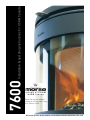
Installation & operating instructions for USA & Canada
7600
Read the entire manual
before installing and using
your Morsø stove
[1]
A French version of the manual can be downloaded at www.morsona.com
Welcome to Morsø …….
Thank you and congratulations on the purchase of your new Morsø heater.
Morsø has been at the forefront of cast iron wood heater design since 1853. Each and every heater is
hand built by skilled crafts-people using the best materials available. However, to extract the best performance, warmth and comfort from your heater it is essential all the installation requirements detailed
within this manual are met. Please take the time to read this manual cover to cover before installation.
Optional Accessories
Morsø offers a comprehensive selection of accessory products (fire tools, fuel buckets) that extends
Form & Function to the hearth. A wide range of maintenance products is also available to keep your new
Morsø heater in tip-top condition.
Morsø 7600-series was designed by Monica Ritterband, currently one of Denmark’s
most sought-after designers. Monica Ritterband is known for her pioneering designs,
which all take their starting point in her unique universes and totally special, organic
language of form and lines. Thus, the Morsø 7600 was also created in this way – it is
completely unique with its circular form, round feminine transitions and its huge glass
window, the biggest in Morsø’s history of stoves.
For optimum use of your Morsø heater we highly recommend using the Morsø Wood Moisture Meter to
ensure good fuel quality as well as the Morsø Stove Thermometer that indicates the correct operating
temperature.
Technical Specifications
Maximum Heat
35,000 BTU/hr
Heat output range (Lab test)
10,875-21,267 BTU/hr
Test fuel load
6 lbs
Particulate Emission
4.4 grm/hr
Log size
11”
Max. Area Heated
1200 ft2
Firebox Dimensions
13” W x 10½” D
Firebox volume/capacity
0.85 ft3
Efficiency rating (as measured by LHV)
75%+
IRS Tax Credit (under American Recovery and
Reinvestment Act of 2009)
Eligible
Outside air supply
Available
Mobile home approved
Yes
Washington State
Compliant
Basic Clearance (using single wall pipe top vent)
Stove to side wall
15”
Stove to rear wall
1”
Stove to corner
2½”
Features
Danish Design and Function
Finest Cast Iron construction
Chrome iron internal castings
Pre-heated clean-glass system
Non-catalytic combustion system
Convection Heater
Reversible flue collar
Vermiculite lining
Ashpan
10-Year Limited Warranty
Low smoke emissions
Made from 98% recycled iron
Recycled packaging
Morsø 7642
Morsø 7644
Morsø 7648
EPA Approved
See installation manual for other configurations
[2]
www.morsona.com
[3]
Table of Contents
Safety Notices & Standards
• Technical Specifications
2
Safety Notices & Standards
5
• Safety Notice
5
• Standards5
• Safety Notices
6
Installation7
• Preparation7
• The chimney / flue system
7
• Clearances to combustible surfaces
13
• Floor Protection
15
• Mobile Home Installation
16
Safety Notice
Please read the entire installation and operation manual before you install and use your new solid fuel
heater. If this appliance is not properly installed, a house fire may result. To reduce the risk of fire, carefully follow the installation instructions. Failure to follow instructions may result in property damage,
bodily injury, or even death.
Contact local building or fire officials about restrictions and installation inspection requirements
in your area. Save these instructions for future reference.
MORSØ JERNSTØBERI A/S . DK-7900 NYKØBING MORS, Denmark
E-Mail: [email protected] • Website: www.morsoe.com
Tested and listed by OMNI-Test Laboratories, Inc, Portland Oregon.
Tested to U.S. Standards ANSI/UL-1482 and Canadian Standards ULC S627
Operation18
• Choosing your fuel
18
• How to light your stove
20
Maintenance23
• Ceramic glass replacement
• Internal Parts
24
25
The heater is listed for burning wood only. Do not burn other fuels.
Standards
The Morsø 7600-series meets the U.S. Environmental Protection Agency’s emission limits for wood
heaters sold on or after July 1, 1990 (EPA Phase 2)
-- Removing the baffle assembly
25
The Morsø 5660 Standard Insert has been tested by OMNI-Test Laboratories, Inc. The test standards
are ANSI/UL-1482 for the United States and ULC S627 for Canada.
-- Door Rope Gasket
25
The heater is listed for burning wood only. Do not burn other fuels
-- Cleaning the Heater and the Chimney Connector
25
-- Ash disposal
25
• Chimney sweeping & inspection
26
Words of wisdom
27
Spare Parts
28
Under specific test conditions this heater has been shown to delivery heat at rates ranging from 10,875
to 21,267 Btu/hr.
Always check Local Building Codes
When installing or operating your Morsø heater always follows the instructions detailed within this
manual. Please store in a safe place and make them available to any person who requires it for future
inspection or servicing.
A building permit may be needed to install a solid fuel heater in your locality. In the US, Standard
NFPA211 may apply, in Canada CAN/CSA-B365-M93 may apply. For clarification consult your local
building inspector.
[4]
www.morsona.com
[5]
Safety Notices
•
This room heater is approved for wood fuel only; Do not burn any other fuel or garbage.
•
If this wood heater is not installed properly, it may result in a house fire. To reduce the risk of fire follow the installation and operating instructions carefully. Failure to properly follow the installation and operation instructions may result in property damage, bodily injury or even death.
•
Never use chemical fire starters or fluid to start your fire.
•
Never burn garbage or flammable fluids.
•
Never use gasoline, gasoline-type lantern fuel, kerosene, charcoal lighter or fluid or similar liquids to start or freshen up a fire in this heater. Keep all such liquids away from the heater while it is in use.
• Where installation issues are not addressed in this manual, consult your local building or fire
officials and where necessary defer to standards NFPA 211 in the US, or CAN/CSA-B365-M93 in Canada.
•
Do not connect this wood heater to any air distribution duct or system and do not install into a chimney shared with another appliance.
•
During it’s operation your wood heater will get hot; Always make provision (fire guard) to adequately protect children, the infirm or inflammable materials from hot surfaces. These hot sur-
faces will cause skin burns if touched.
•
Never allow your wood heater to overheat; Operate only within the guidelines set out in this manual.
•
Never operate this heater if any of the components (inc’ glass) are cracked or broken. Replace broken or damaged component before use.
•
Always install smoke and carbon monoxide detectors in your home. Adhere to the recommended positioning and maintenance instructions.
•
Cooktop hoods, clothes driers, and similar extraction units can have a detrimental effect on chim-
ney draft; Avoid installing your wood heater in areas where there are present unless you are able to provide sufficient or additional outside air to the room.
•
Your heater should be properly sized to the immediate area you need to heat; An under-sized
heater may not deliver the required heat output without overheating and an oversized heat may produce too much heat.
•
Always use approved chimney and chimney lining materials.
•
Your chimney should be inspected and swept by an approved chimney sweep at least once every year, dependent upon usage.
[6]
www.morsona.com
Installation
Preparation
We recommend installation be performed by an approved Morsø dealer or fully qualified installer. In any
event, Morsø heaters are very heavy and we recommend the installation be performed by two people.
Always consult your local building or fire officials to determine if any permits are required for installing
a solid fuel heater in your area. You may also need to inform your Homeowners Insurance Company.
After unpacking, check that fire bricks or liners are firmly in position and have not shifted in transit.
Check also that the air control works freely.
Before starting the initial fire, make sure that the baffle is placed correctly.
The chimney / flue system
Note that the flue system must be independently secured and must not rely on the stove for support.
Use a residential type masonry or listed type HT factory-built chimney.
High Temperature (H.T.) Chimney Standard UL-103-1985 (2100º F.) or a code-approved masonry
chimney with flue liner for the USA, and High Temperature (650ºC) Standard ULC S-629 for Canada.
The internal dimensions of the chimney connector and chimney must not be less than 6 inches diameter (or equivalent cross section), and should not be significantly larger than this. Too large a section will
tend to allow the flue gases to cool excessively, causing sluggishness or unpredictability in the stove’s
performance.
We recommend the length of the chimney system should be at least 16 feet (not required) above the
stove in normal domestic situations, measured from the flue collar to the top of the chimney.
Local conditions for example - roof constructions, large trees nearby and high altitude, may influence
the chimney draft. Therefore, contact your local professional chimney sweep or your Morsø dealer prior
to installation.
[7]
Typical Factory-Built or Masonry Chimney Installations
See page 10 for key
[8]
www.morsona.com
See page 10 for key
[9]
Typical Installation
Installation Key
1
DVL or DuraBlack 11 Tee with Tee Cap 11 Tee with Tee Cap
2
Ceiling Support Box
12 Tee Support
3
Wall Thimble
13 Chase Top Flashing
4
Chimney Pipe
14 Base Tee/Double Tee
5
Attic Insulation Shield
15 Anchor Plate or Anchor Plate with Damper
6
Flashing
16 Roof Support
7
Storm Collar
17 Finishing collar
8
Chimney Cap
18 DVL Adapter, DuraBlack Slip, Connector, or SnapLock Adapter
9
Elbow
Storm Collar
Flashing
19 Stove Adapter
10 Elbow Strap
20 Square Ceiling Support Box
Refer to our Typical Installation drawings to select the appropriate component parts for your installation.
•
Chimney Cap
DVL/DuraBlack Chimney Adapter must be used when connecting DVL pipe to a Ceiling Support
Box or Finishing Collar. When connecting DuraBlack pipe, a DVL/DuraBlack Chimney Adapter,
DuraBlack Slip Connector, or Snap-Lock Adapter must be used.
• Wall Thimble must be installed with an appropriate length of chimney pipe for all horizontal
through-the-wall installations. To accommodate thicker walls, the telescoping pieces of the Wall
Thimble can be separated, and a field-fabricated extension may be installed.
•
Attic Insulation Shield must be used in all installations that pass through an attic, regardless of
whether the attic is insulated or not.
•
Firestop Radiation Shield must be used when a chimney passes through a floor or ceiling without
a support box.
Note: Chimney Installation Diagrams supplied by kind permission of Simpson Duravent (Duravent.com).
Components shown may differ from manufacturer to manufacturer.
Attic Insulation Shield
Firestop Radiation
Shield
Adjustable Wall Strap
Chimney Pipe
Ceiling Support Box
DVL or DuraBlack
Chimney Adapter
DVL or DuraBlack Pipe
Appliance adapter
[ 10 ]
www.morsona.com
[ 11 ]
Flue Connection
The stove is supplied from the factory with round blanking plates blocking off the top and rear flue exits
(behind the rear shield plate). A cast iron flue collar is placed inside the firebox during transit.
Use a 24 MSG black chimney connector or listed double wall chimney connector. Refer to local codes
and the chimney manufacturer’s instructions for precautions required for passing a chimney through a
combustible wall or ceiling. Remember to secure the chimney connector to the product using a minimum of three screws to each adjoining section.
The flue collar can be fitted to the rear outlet. Simply knock out the round panel on the rear plate to
reveal the cast iron plate. Untwist the blanking plate and the flue collar and swap their positions. Resecure by pushing down and tighten the enclosed screws.
Position the stove and connect to the flue system.
Connection to the existing chimney - using single wall or double wall chimney connector.
A chimney connector is the double-wall or single-wall pipe that connects the stove to the chimney. The
chimney itself is the masonry or prefabricated structure that encloses the flue. Chimney connectors are
used only to connect the stove to the chimney.
Double-wall connectors must be tested and listed for use with solid-fuel burning appliances. Singlewall connectors should be made of 24 gauge or heavier gauge steel. Do not use galvanized connector;
it cannot withstand the high-temperatures that smoke and exhaust gases can reach, and may release
toxic fumes when under high heat. The connector must be 6 inches (150mm) in diameter.
Distance to walls and lintel
When the stove is positioned near combustible materials, observe all current local and national building regulations with regards to clearances. Whatever regulations apply to your area, do not in any case
install the stove within 8 inches of combustible materials from the sides or 16 inches above the top of
the stove (fireplace installations require greater clearances above the stove - see below in the clearance
chart). These distances may need to be increased if the materials (precious furniture) are sensitive to
heat. Note also that wallpaper and other decorative materials may become detached with the effects of
heat and care should be taken to ensure that they do not fall onto the stove in such an event.
When the stove is positioned near non-combustible materials, a gap of 4 inches or more is recommended for cleaning purposes and to ensure that heat circulates around the stove and out into the room.
Clearance Requrements
A. Sidewall to unit
B. Backwall to unit
Freestanding residential Installation top vent
using single wall connector
USA
Canada
15”
381 mm
1”
26 mm
C. Cornerwall to unit
2½”
64 mm
D. Sidewall to connector
21”
533 mm
E. Backwall to connector
7”
178 mm
F. Cornerwall to connector
8½”
216 mm
G. Unit to ceiling
47”
1194 mm
Minimum clearances to combustibles:
Backwall
Adjacent wall
Adjacent wall
If possible, do not pass the chimney connector through a combustible wall or ceiling.
If passage through a combustible wall is unavoidable, refer to the sections on Wall
Pass- Throughs. Do not pass the connector through an attic, a closet or similar
concealed space when installing the chimney connectors.
It is important to keep the flue gases moving smoothly in the right direction. Do not vent into a large
void; rather form one continuous section all the way up. Use mild bends (e.g. 45º vs. 90º) rather than
sharp angles where a change of direction is required. All parts of the venting must be accessible for
cleaning purposes.
In horizontal runs of chimney, maintain a distance no less than18 inches from the ceiling. Keep it as
short and direct as possible, with no more than two 90 degree turns. Slope horizontal runs of connector
upward 1/4 inch per foot (20 mm per metre) going from the stove toward the chimney. The recommended maximum length of a horizontal run is 3 feet (1 metre), and the total vertical length should be no
longer than 8 feet (2.5 metres).
Information on assembling and installing connectors is provided by the manufacturer’s instructions.
Clearances to combustible surfaces
Be sure the installed stove and chimney connector are correctly distance from near by combustible
materials. See the clearance paragraph page 13.
Sidewall
Where passage through a wall or partition of combustible construction is desired, the installation shall
conform to CAN/CSA-B365.
[ 12 ]
www.morsona.com
[ 13 ]
Clearance Requrements
Freestanding residential Installation top vent
using double wall connector
A. Sidewall to unit
USA
Canada
15”
381 mm
B. Backwall to unit
Floor Protection
Floor protection requirements
NON -COMBUSTIBLE MATERIAL BENEATH STOVE
USA
Canada
A. Extending distance, back
-
8’’(200 mm)
8’’(200 mm)
1”
26 mm
B. Extending distance, right side
6”
C. Cornerwall to unit
2½”
64 mm
C. Extending distance, left side
6”
8’’(200 mm)
D. Sidewall to connector
21”
533 mm
D. Extending distance, front
16”
18’’(450 mm)
7”
178 mm
F. Cornerwall to connector
E. Backwall to connector
8½”
216 mm
G. Unit to ceiling
47”
1194 mm
alcove installation
using double wall connector
Clearance Requrements
USA
Canada
A. Sidewall to unit
15”
381 mm
B. Backwall to unit
1”
26 mm
C. Cornerwall to unit
-
-
D. Sidewall to connector
21”
533 mm
E. Backwall to connector
7”
178 mm
F. Cornerwall to connector
-
-
33½”
851 mm
-
-
G. Unit to ceiling
W. Minimum alcove width
D. Maximum alcove depth
G. Alcove ceiling above stove top
32”
813 mm
33½”
851 mm
US:
FLOOR PROTECTOR MUST BE
NON-COMBUSTIBLE MATERIAL
IT MUST EXTEND FRONT/SIDE/REAR AS INDICATED
CANADA:
FLOOR PROTECTOR MUST BE
NON-COMBUSTIBLE MATERIAL
IT MUST EXTEND FRONT/SIDE/REAR AS
INDICATED
MAXIMUM ALCOVE DEPTH 32” (813 MM)
[ 14 ]
Sidewall
Sidewall
Backwall
www.morsona.com
[ 15 ]
WARNING:
NEVER DRAW COMBUSTION AIR FROM A WALL, FLOOR OR CEILING CAVITY OR FROM ANY ENCLOSED
SPACE SUCH AS AN ATTIC OR GARAGE.
DO NOT INSTALL IN A BEDROOM OR A ROOM WHERE PEOPLE SLEEP.
Mobile Home Installation
The Morsø 7600 can be installed in a mobile home if equipped with an outside combustion air kit, a
terminal cap with a spark arrestor, and if it meets the following installation requirements:
•
•
CAUTION:
A
THE STRUCTURAL INTEGRITY OF THE MOBILE HOME FLOOR, WALL, AND CEILING/ROOF MUST BE
MAINTAINED (I.E., DO NOT CUT THROUGH FLOOR JOIST, WALL STUD, CEILING TRUSS, ETC.)
The stove must be secured to the mobile home structure by bolting through the hearth pad and
into flooring.
7642 & 7644 are prepared for securing.
The 7648 requires you drill three holes in the floor at specific points (see diagram below).
SPARK ARRESTOR
PARE ÉTINCELLES
The stove must be installed with a listed Type HT chimney connector, HT Chimney, and terminal cap with spark arrestor. Never use a single wall connector (stovepipe) in a mobile home
installation.
•
In Canada, this appliance must be connected to a 6” (152 mm) factory-built chimney conforming to CAN/ULC-629M, STANDARD FOR FACTORY BUILT CHIMNEYS. Floor protection as
referenced in section 1.5 must be followed, as well as use of Canadian Floor Protector.
•
Follow the chimney and chimney connector manufacturer’s instructions when installing the
flue system for use in a mobile home.
•
Intake air piping can be installed through the floor into a vented crawl space or through the
wall of the residence to obtain outside air.
•
Install in accordance with 24 CFR, Part 3280 (HUD).
•
NOTE: Top sections of chimney must be removable to allow maximum clearance of 13.5” from
ground level for transportation purposes.
0
ROOF FLASHING/SUPPORT
SOLIN TOUT/SUPPORT
lISTED CHIMNEY
CONNECTOR
CONDUIT CHEMINÉE
RÉPERTORIE
OUTSIDE AIR
EXTÉRIEUR AIR
658"
168 mm
Floor protection requirements in section 1.5 must be followed precisely.
658"
168 mm
•
LISTED CHIMNEY
CHEMINÉE REPERTORIÉE
STORM COLLAR
EMBASE TEMPÉTE
FLOOR PROTECTOR
PROTECTION DU SOL
8"
8 mm
8"
8 mm
3
3
378"
97 mm
A-A
A
Acid Protection
If acid-washing the masonry around the stove, protect the stove surface with an acid-proof cover.
Rev. Revisions
Sign.:
Date:
Date of print: 25-05-2010
20.05.10
RSV
Construction:
Title:
Outside Air Supply
Released:
Skorstenskitse
Only mobile home
approved
heaters
may
be
installed
into
mobile
homes
and
it
is
a requirement that
Material:
Format:
A4
outside air isWeight:
supplied
directly to the heater.
Scale:
268,91 kg
1:15
0
Morsø 7600
Model no.
Itemno.:
no.:
Drawingtype:
However, in every
residential situation where the room has poor airDrawing
infiltration
via doorways, windows
of file:
a a non-combustible
and the like, Location
providing
a dedicated outside air supply may be required.7600-125
By attaching
This drawing is Morsø Jernstøberi A/S' property and must not be sold, lended or copied without any written authorization from the company.
conduit (ducting) directly to the air intake of the heater, outside air can be delivered directly to the combustion chamber. Some models may require an additional (optional) outside air kit. The conduit used for
providing outside air should have a free space equal to but no less than 3” diameter.
758"
195 mm
8"
8 mm
[ 16 ]
Date of print: 29-09-2010
3
www.morsona.com
Dim. without indication of margin acc. to DS/ISO 2768-1 m
Material:
Cast Iron GG15
Weight:
9,98 kg
Model no.
7616
Borefixturer:
Drawingtype:
Work up Drawing
Location of file:
C:\UDV\tegninger\7600\7600-16 Pedistalfod.SLDPRT
Rev. Revisions
Title:
Construction:
Sign.:
Date:
RSV
21.11.2008
Boreanvisning for evt. fastmontering Released:
Drilling instructions for potential fixing
Morsø 7600
Format:
Scale:
A3
1:2.5
Itemno.:
Drawing no.:
Page: 3
7600-16 a
This drawing is Morsø Jernstøberi A/S' property and must not be sold, lended or copied without any written authorization from the company.
U:\udv\Tegninger\TILBEHØR\Skorsten\Ovn med skorsten til vejledning.SLDASM
Outside air is particularly important when the heater is to be installed into a well sealed room, or where
an extractor hood or ventilation system interferes with the room’s natural air pressure. Avoid placing
the outside air supply onto a wall that that is usually subject to negative pressure from normal wind
pattern.
[ 17 ]
Operation
Before you light your heater here are a few considerations.
Your new Morsø heater is approved for use with Solid Wood Fuel Only. DO NOT OVERHEAT. If the heater
or chimney connector glows, your heater is overheating. Use Morsø stove thermometer for correct
operating temperature (#62901200).
Have your chimney inspected and cleaned at least once a year by an approved and certified chimney
sweep.
Be aware; if the heater is not operated or installed in accordance with the manufacturers instructions
or the fuel quality is poor, creosote buildup may occur within the flue thus increasing the risk of a
chimney fire.
To reduce the risk of smoke and flame spillage, operate the heater only with door(s) fully closed.
Caution:
Your heater will be hot while in operation. Keep children, the infirm, clothing and furniture protected at
all times.
Choosing your fuel
All types of natural wood can be burned in your heater, but it must be well-seasoned and dry.
The operating position of the air control lever (or dial) will vary and so will your loading intervals; both
are dependent on several factors, your lighting technique, the chimney draft, the fuel used and the heat
requirement etc.
Some basic techniques are outlined below.
In most models the heater is equipped with three air supplies:
Primary air is controlled by the air control lever situated beneath the ash lip or above the door, in some
models, on the door. Primary air passes through internal channels where it is preheated and eventually
washes at high speed down the back face of the door glass – the air-wash system. This super-heated
air helps to achieve high combustion efficiency of the volatile gases driven from the fuel.
Secondary air is factory-set and enters the combustion chamber via the baffle assembly (or tubes)
located under the roof of the firebox. This source of combustion air mixes with the volatile gases and
given the right conditions, secondary combustion takes place making for very clean and low emissions.
This air supply is constant and cannot be varied.
Pilot air or tertiary air enters the combustion chamber through a hole located behind the front bottom
section of the fire opening (below the front grates). This air ensures the embers in the fire bed stay hot.
Pilot air supply is factory-set and cannot be varied.
For the correct combustion efficiency and heat output, wood fuel should contain no more than 18%
moisture; this can easily be checked by using the Morsø Wood Moisture Meter (part # 62929900).
Lighting and loading procedure
When you are ready to light your heater, it is essential to quickly establish a chimney draft therefore
the initial lighting process will require you to leave the door cracked open for a few minutes. For added
safety, it is of course essential that you pay close attention to the heater at this point.
When wood fuel is cut to length you should allow for an inch gap between the fuel and side walls of the
firebox so as to ensure adequate circulation of the gases. Cut wood should also be split down middle to
allow for the quick release of moisture.
During the process it is also important to create and maintain a good bed of ash (1” thick) in the fire
bed. To achieve this be prepared to use 4-6lbs of dry kindling (thin sticks) during the initial lighting
process.
To naturally season wood fuel, it should be stacked and stored under cover in an airy location where
fresh air can move around the stack. Some soft woods may take as little as one good summer to season whereas harder woods such as oak, maple, and elm may require up to 18 months or more.
Before your start the lighting process fully open the primary air control lever (or dial).
Avoid burning overly dry wood that is gray in color as under certain conditions it can cause performance
problems, such as back-puffing and poor performance. Well seasoned wood will be light to hold and
when looking at the ends it will show signs of cracking from the center outwards.
If your wood spits or sizzles when burned and your heater’s door glass persistently clouds up, it is possible that your wood is not properly seasoned (although a poor chimney draft can also cause this).
Never use drift wood (from the sea) as salt content may cause corrosion; construction wood that may
have been impregnated with chemicals should also be avoided.
Starting the first fire
When lighting your heater for the first time or after dormant periods, the initial fire should be fairly
gentle so that the finish paint can cure and the main cast plates of the heater can expand gently and
settle into position.
The heater paint cures at higher temperatures and it should be expected that during the initial firing
process a slight odor will be emitted into the room therefore, it is important to ventilate the room well
during this process.
[ 18 ]
www.morsona.com
[ 19 ]
How to light your stove
1. How to light the stove
As shown in the picture to the left you need the following:
2 fire lighthers (or 5-10 scrunched-up sheets of newspaper)
1 kg of dry kindling
Approx. 2-3 lbs. of chopped firewood
2. You should always have an insulating layer of ashes from
previous firings in the bottom of the fire chamber.
1” of ash is a suitable base for the wood.
Start by placing a couple of logs, approzimately 1 lb., in the
bottom of the burn chamber.
3. Arrange the kindling
Place approximately 2 lbs. of dry kindling wood on top of the
logs. Place a couple of kindling bags or newspaper just below
the top layer of kindling wood.
4. Lighting the kindling
Light the kindling bags or newspaper
5. Before lighting, fully open the primary air supply.
The flames work their way slowly downwards from the top.
6. Leave the stove door ajar
After 5-10 minutes the heat will produce draft through the
chimney, and the door can be shut.
7. Embers
After approximately 45-60 minutes, the last flames go out,
and a good layer of embers has been formed. More wood
should be added while there are still glowing embers. Use a
poker or ash scraper to spread the embers, but ensure that
most of them are positioneded at the front of the stove.
8. Re-Fuelling
Place three pieces of wood of approx ½ lb. each and approx.
9,8" long over the embers in a single layer, with a distance of
approx. ½” between each piece.
When the air controls are opened fully, and the door is closed,
the wood will ignite within 2-3 minutes.
9. Optimal combustion
Finally, adjust the air supply control to the required position
to give optimal combustion. Maintaining a good fire box temperature will ensure secondary combustion of the smoke and
gases giving a clean and efficient burn. The stove should be
refuelled only while glowing embers remain.
10. How much ash should be left in the stove?
Keep a 1" thick layer of insulating ash. The ash layer insulates the bottom of the stove in the same way as the fire bricks
or vermiculite board on the sides of the stove. This ensures a
high combustion temperature which contributes to a cleaner
more efficient combustion.
Furthermore, the ash layer protects the grate against premature failure and increasing its life expectancy. Empty the
ashpan as required. Store any hot ashes in a suitable noncombustibleash bucket until all embers are fully extinguished, cold ash can then be disposed of with the rest of your
household waste.
[ 20 ]
www.morsona.com
[ 21 ]
Do not for any reason attempt to increase the air flow through your heater by altering or tampering
with the air control mechanism. This could lead to serious safety and health hazards.
Warning: Fireplace heaters must never be left unattended when the door(s) is open.
If the door is left partly open, gas and flames may be drawn out of the heater’s opening thus
increasing risks from both fire and smoke. We recommend you to fit smoke and carbon monoxide
detectors in the room where the heater is installed.
DO NOT OVERHEAT THIS HEATER. Overheating may cause a house fire, or can result in permanent
damage to the heater. If any part of the heater glows, you are overheating.
The maximum recommended weight of wood fuel per load is 2 kg/h/4.5Ibs (approx 3 split
logs).
Under normal firing, the average flue temperature on the single wall stove pipe, measured 8" (200 mm)
above the stove, is approx. 300° C (550°F). The maximum flue temperature on the stove pipe must not
exceed 450° C (750°F). If the flue temperature exceeds 450°C (750°F), it is considered as over firing and
may cause premature wear and tear of the stove. Damaged caused by overheating is not covered under
warranty.
To help gauge the correct running temperature of your stove, we recommend you use the Morsø Stove
Thermometer (part # 62901200). The Stove Thermometer magnetically attaches onto the stove pipe
approx 8” (200 mm) above the stove’s top plate and measures the surface temperature of the stove pipe.
Please see your authorized Morsø Dealer for availability.
Chimney Draft
If smoke or fumes spill from your heater when lighting up and reloading, or if the fire simply will not respond, a poor chimney draft is almost certainly to blame. (In a very few cases, there may be insufficient
fresh air getting into the room - see installation advice above). Take advice from your dealer or chimney
expert on how best to upgrade your flue system and improve the draft.
Simple rules for controlling your heater
If you want less heat, put fewer logs on the heater and reduce the amount of air however, it is extremely
important to maintain a good layer of glowing embers throughout the combustion process.
Low heat output = less wood & less air
High heat output = more wood & more air
Soot particles will accumulate on the glass and vermiculite bricks if the heater is operated too low or if
your wood is not well seasoned.
Maintenance
A clean well maintained heater is essential for good health and a safe home environment. Your heater
should be properly inspected at least once a year.
When performing any maintenance procedure always wear protective clothing and always wear safety
goggles and gloves.
Exterior Maintenance
The heater’s outer surface is painted with a heat-resistant paint. Generally, it is best kept clean by using
vacuum cleaner with a soft brush attachment or, by wiping with a damp lint-free cloth.
Over a period of time, the dark gray painted surface may become lighter. The surface can easily be
restored using our CFC-free aerosol touch-up paint (product code - 62902316DG) Morsø stove paint is
available through your approved Morsø dealer.
In accordance with the instructions, this can be applied in minutes. Be aware however, that the new
coat of paint will need to go through the curing process as described earlier thus, you will need to ventilate the room when lighting the heater for the first time.
Internal Maintenance
Transparent Ceramic Glass
If the heater is operated in accordance with the instructions, there should be little or no dirt accumulation on the glass surface. If particles have settled during operation, it is probable that this will burn
away as the fire temperature is increased.
For heavier deposits that will not burn off, Morsø glass cleaner (product code 62902600) can be applied
when the glass is cold. Note: never use abrasive cleaners or scrapers on the glass surface.
Why does my glass get dirty?
• Fuel too wet and/or too thick.
• Fuel not split.
• Combustion chamber temperatures too low – maintain glowing coal bed.
• Poor chimney draft.
• Under firing the stove.
Safety Note: If the glass breaks, replace it with genuine Morsø ceramic glass immediately. Do not
use your heater with a cracked or broken glass; this can lead to overheating.
Installing the glass is relatively simple however; you should never install the ceramic glass when the
heater is in operation.
[ 22 ]
www.morsona.com
[ 23 ]
Ceramic glass replacement
Ceramic glass cannot be recycled because it has a higher melting point than ordinary glass.
If ceramic glass is mixed with ordinary glass, the recycled material is spoiled and the recycling process
may be halted. Ensure the heater’s glass does not end up with ordinary recycled waste. It should be
presented separately to your local recycling center as ceramic glass.
Internal Parts
The flame-path equipment - consisting of firebricks/vermiculite liners, bottom and front grates,
ceramic glass, baffle plate assembly, pilot air assembly and chimney connector collar are the main
components that are subjected to the rigors and heat of the fire; as a result it should be expected that
these parts will need to be replaced from time to time as a matter of routine.
NOTE: The flame-path equipment, the ceramic rope and the paint finish are not covered by the
Morsø manufacturers warranty.
Replacement parts can be purchased through your approved Morsø dealer. We recommend that all
damaged or distorted parts be replaced as soon as possible to avoid collateral damage.
Should the baffle plate assembly become distorted from overheating, the combustion system will no
longer function properly and the heater’s efficiency will be severely compromised. Replace it as soon as
possible.
Removing the baffle assembly
If the baffle is damaged or warped due to overheating, it is vital to replace it at once.
First, carefully remove the vermiculite liners from the internal sides of the combustion chamber
(firebox). Then, loosening the 3 x M6 allen screws that secure the baffle assembly in place; these
are located along the internal back wall of the firebox. The baffle can now be carefully lifted and
removed from the stove through the door.
The new baffle should be fitted and fastened before the side bricks are replaced. Ensure that all parts
are fitted correctly before lighting up the stove.
Door Rope Gasket
The ceramic rope gasket around the perimeter of the door(s) may harden over a period of time. It
should be checked for air-tightness at least once every year.
Replacement procedure
1. Detach the door from the body (See door removal section) and place face-down on a protective, non-abrasive surface.
2. Unscrew the screws that hold the glass clips.Title:
If the stove has been
usedRSVfor01.03.2010
a number of years the Construction:
Released:
screws may be tough to remove. DO NOT FORCE
THEM. If7600
theNAscrews
are tight, try applying heat Glasmontering
Material:
Format:
A4
(blow-torch) directly
onto the screw head.
Glass mounting 7600 NA
Date of print: 01-03-2010
Rev. Revisions
Weight:
128,21 kg
Model no.
-
Morsø 7600
Date:
Sign.:
Scale:
1:5
Itemno.:
no.:
In the event thatDrawingtype:
a screw
does sheers off remove the remaining Drawing
thread
by drilling down its center Assembly
Location of file:
7600-119but
a do not use a larger with 1/8 inch high
speed steel drill bit. Smaller drill bits may be successful,
This drawing is Morsø Jernstøberi A/S' property and must not be sold, lended or copied without any written authorization from the company.
bit. Make sure the bit stays away from the edge of the screw thread as this may damage the thread in the door casting.
U:\udv\Tegninger\7600\7600 Assembly.SLDASM
3. Remove the old ceramic gasket material and clean the surface beneath with wire wool or emery paper to remove any loose particles.
4. Place the new gasket material in position around the perimeter of the window area, making sure to pinch it in such a way that all four sides make a continuous seal. Leave no gaps.
5. Place the new ceramic glass in position onto the new gasket and fasten by hand using new screws.
6.
Finally, give each of the screws an extra half turn or so, just enough that the glass is held tight and will not dislodge when cleaning. IMPORTANT! Do not over-tighten the screws as this may put excessive pressure on the glass, resulting in cracking. To reduce the risks of accidental breakage avoid striking the glass, slamming the door or closing it onto a protruding log.
[ 24 ]
www.morsona.com
To check for air-tightness simply run a lit incense stick around the perimeter of the door when the
stove is in operation; if the fine trail of smoke is drawn into the stove at any point, the gasket needs
replacing. Alternatively, close the door(s) onto a slither of paper; if the paper can be easily removed with
little force, it’s time to change your door gasket.
Genuine Morsø door rope gasket kits (inc’ adhesive) are available from your approved Morsø dealer.
Cleaning the Heater and the Chimney Connector
It is recommended that the area above the baffle plate assembly and around the chimney connector
collar is inspected once a month for any soot or debris collection. If soot or debris is allowed to accumulate in this area, it could adversely affect the chimney draft and general operation. Typical symptoms
of blockage are poor and sluggish draft, smoke spillage when opening the door, dirty glass and dirty
firebox liners.
In any case the chimney should be inspected at least once every year, preferably in the summer to
ensure that other blockages such as birds nest have not occurred.
Ash disposal
The level of ash-removal is dependent upon the level of use, the type of wood burned and the strength
of chimney draft. A 1” ash bed should be maintained during general and excess ash should be removed
when necessary.
Where the heater is equipped with an ash pan, excess ash should be emptied regularly. A full ash pan
allowed to build up underneath the bottom grate could trap heat and lead to premature failure of the
grate/pilot air assembly.
[ 25 ]
Caution:
Never empty ash when the heater is in operation.
Never use your household or shop vacuum cleaner to remove ash from the heater as it may still
contain hot coals.
Always dispose of ash in a metal container.
Creosote formation
Your Morsø heater is equipped to burn the wood cleanly and efficiently however, if the chimney draft
is poor or when wood is burned too low or too slowly, tar and other organic vapors can be produced
and when combined with expelled moisture from the fuel, hazardous creosote is formed. The hazard
is worsened when the creosote vapors condense inside cool chimney and the risk of a chimney fire is
dramatically increased.
A monthly inspection of the flue is highly recommended.
Chimney sweeping & inspection
No matter how often you use your Morsø heater you should establish a monthly inspection routine of
the heater and chimney system especially during the heating season.
Perform a chimney inspection when the heater is not in use. Using a mirror, look up through the
chimney connector collar and look for visible signs of creosote build-up.
If you unable to inspect the flue system through the heater, it must be disconnected from the chimney
connector to provide better viewing access.
Cleaning the chimney must be done using a brush the same size and shape as the flue liner or chimney
system. Run the brush up and down the liner several times until all soot deposits have fallen to the bottom of the chimney where they can be removed through a clean-out door or from inside the heater (if
still connected) using a vacuum cleaner.
Leaving the heater for extended periods
Important notice:
When the heater is to be left unused for a long period of time (summer months etc) it is essential to
clean it out thoroughly and leave the primary air control lever (or dial) open to allow airflow around the
combustion chamber and chimney. Ventilating your heater and chimney will prevent excessive corrosion
from moisture present in the chimney.
Make sure that the chimney has adequate protection from the rain and that rain water cannot come
into contact with the heater; install a chimney rain cap, but do not under any circumstances block off
the flue completely.
Warning: If moisture is allowed to settle within the heater, rust will form. As it takes a grip rust will
cause cast iron to swell. This can lead to undue pressure on the plate joints and in turn may result in
damage to the heater.
Words of wisdom
It is good practice to thoroughly clean the heater immediately after the heating season. Adding a desiccant, such as kitty litter into the heater bottom will help absorb excess moisture during the summer
months. However, be sure to remove this prior to the heating season.
Thank you for choosing Morsø.
We hope you have many years of carefree warmth in its company. Some initial experimentation with
loading and running techniques will help decide your normal routine. If you still have any questions
after this short learning phase, please refer to your approved Morsø dealer who should be able to help
If for any reason you require further assistance, please contact us in writing at the address on the front
of this manual.
Some models may require baffle removal (see page 25)
The chimney connector should be cleaned in a similar way using a stiff wire brush. This procedure
might be better performed outside. Reinstall the connector sections after cleaning, making sure to
secure the joints between the individual sections with sheet metal screws.
If you cannot inspect or clean the chimney yourself, contact your local certified chimney
sweep or your approved Morsø Dealer.
If you do experience a chimney fire, you must act promptly
1.
Completely close the primary air control.
2.Ensure ALL persons have vacated the building.
3.
CALL THE FIRE DEPARTMENT.
Annual maintenance
Prior to every heating season you should thoroughly clean and inspect the entire installation, repairing
any damage, and replace any parts that show signs of wear & tear.
Thoroughly clean and inspect the chimney and chimney connector.
Have a contractor make any necessary repairs to a masonry chimney.
Check door & ceramic glass gaskets for wear or compression and replace if necessary.
Check the glass for cracking; replace if needed.
Check door and handles for tightness and adjust if needed.
[ 26 ]
www.morsona.com
[ 27 ]
[ 28 ]
Date of print: 16-12-2010
www.morsona.com
Date of print: 16-12-2010
7670
7648
7
47
46
17
9
58
99
28
29
3
5
76
78
46
32
48
100
1
82
63
75
32
78
4
79
32
32
67
67
63
32
62
60
33
32
81
63
66
23
27
25
26
24
28
26
29
30
11
7600 Cumbustion Chamber
32
41
19
32
*
50
51
80
*
56
77
101
33
66
20
94
32
102
41
32
14
6
83
32
44
92
44
32
7642/7644
1
45
32
33
21
74
73
72
15
71
17
52
100
50
44
32
10
70
43
68
69
12
32
37
2
33
36
35
34
37
32
37
32
87
88
*
85
86
18
13
5
Assembly
40
98
49
98
39
49
38
41
Tilføjet pinolskrue pos. 101.
53
Morsø 7600
Parts Diagram 7600 NA
Res. tegn. 7600 NA
Title:
Side 1 of 2
A2
1:7
Date:
17.11.2008
RSV
28.05.2009
01.09.2009
11.02.2010
05.05.2010
16.12.2010
Sign.:
RSV
RSV
RSV
RSV
RSV
7600-500 j
Drawing no.:
Itemno.:
Scale:
Format:
Released:
Construction:
To skruer ændret til én pos. 67, nederst v. stang til håndtag.
Rev. Revisions
f
Ændret skruer pos. 31 til pos. 100.
Tilføjet forrist pos. 115.
g
Ændret pos. forrist fra 115 til 102.
55
h
54
i
17
33
j
43
43
69
68
94
95
94
44
32
[ 29 ]
C:\UDV\tegninger\7600\7600 Assembly.SLDASM
Assembly
-
96
94
32
Ændret skruer pos. 31 til pos. 100.
g
Morsø 7600
05.05.2010
11.02.2010
Side 2 of 2
A2
1:7
Date:
17.11.2008
RSV
28.05.2009
01.09.2009
Sign.:
RSV
RSV
16.12.2010
7600-500 j
Drawing no.:
Itemno.:
Scale:
Format:
Released:
Res. tegn 7600 NA
Parts Diagram 7600 NA
Construction:
Title:
Rev. Revisions
To skruer ændret til én pos. 67, nederst v. stang til håndtag.
Tilføjet pinolskrue pos. 101.
f
RSV
Tilføjet forrist pos. 115.
RSV
RSV
Ændret pos. forrist fra 115 til 102.
i
32
44
92
44
32
93
h
j
84
84
89
90
87
88
91
32
44
44
This drawing is Morsø Jernstøberi A/S' property and must not be sold, lended or copied without any written authorization from the company.
Location of file:
Drawingtype:
Model no.
Weight:
Material:
97
This drawing is Morsø Jernstøberi A/S' property and must not be sold, lended or copied without any written authorization from the company.
C:\UDV\tegninger\7600\7600 Assembly.SLDASM
Drawingtype:
Location of file:
-
61
42
Model no.
Weight:
Material:
8
7
59
Spare Parts
POS.NR.:Parts:
7642 NA
1
Base plate
447601xx
2
Top frame
447607xx
3Door
447603xx
4
Front frame
447656xx
5
Rear plate, outside
447610xx
6
Top plate, outside
447611xx
7
Rear plate, inside
44760400
8
Side plate, inside, right
447657xx
9
Side plate, inside, left
447630xx
10
Top plate, inside
447605xx
11Glass
79760100
12
Air Canal, top
44761500
13
Air Canal, rear
44765400
14
Intermediate plate
34761200
15
Brick, back
79760700
16
Air Canal, front
447613xx
17
Side plate, outside
447609xx
18
Brick, side, right
79760300
19
Brick, side, left
79760400
20
Ash tray, front
447617xx
21
Ash tray
71760400
22Screw
73861800
23
Secondary Damper
71760100
24
Secondary Handle
71760200
25
Close plate, sec. Damper
71760300
26
Distance tube
71810200
27
Distance tube
71810300
28Washer
736106
29Screw
74162000
30Screw
73851100
31Screw
73861300
32Washer
791891
33Screw
731620
34Cover
448120xx
35
Fitting for Cover
71813200
36Screw
731608
37Screw
731635
38
Rondelle, rear, outside
71762100
39
Distance tube
541439
40
Rondelle, rear, inside
542633
41Screw
73861400
42Nut
735006
43Screw
791835
44Screw
731625
45Washer
736210
46Screw
73850800
47
Glass fitting
71611361
48
Glass fitting
54181361
49Screw
73861000
50
Baffle plate, top
71761700
52
Distance tube
54143700
[ 30 ]
www.morsona.com
7644 NA
7648 NA
---
447607xx
447603xx
447656xx
447610xx
447611xx
44760400
447657xx
447630xx
447605xx
79760100
44761500
44765400
34761200
79760700
447613xx
447609xx
79760300
79760400
447617xx
71760400
73861800
71760100
71760200
71760300
71810200
71810300
736106
74162000
73851100
73861300
791891
731620
448120xx
71813200
731608
731635
71762100
541439
542633
73861400
735006
791835
731625
736210
73850800
1611361
54181361
73861000
71761700
54143700
--447607xx
447603xx
447656xx
447610xx
447611xx
44760400
447657xx
447630xx
447605xx
79760100
44761500
44765400
34761200
79760700
447613xx
447609xx
79760300
79760400
447617xx
71760400
73861800
71760100
71760200
71760300
71810200
71810300
736106
74162000
73851100
73861300
791891
731620
448120xx
71813200
731608
731635
71762100
541439
542633
73861400
735006
791835
731625
736210
73850800
1611361
54181361
73861000
71761700
54143700
POS.NR.:Parts:
53Cover
54Bar
55
Distance tube
56
Plug f. Door
57
Fittig f. Door
58
Fitting f. Handle
59
Fitting for Flue Collar
60Pedestal
61
Fittig f. Door
62
Foot, f. Pedestal
63Screw
66Washer
67Screw
68
Flue Collar
69Screw
70
Stop Bar
71
Baffle plate, cast iron
72
Baffle plate, stainless
73Screw
74Screw
75
Jet, pilot air
76
Tightening tape, f. glass
83
Door bottum part
84
Base plate, bottom section 85
Rubber Stop
86Screw
87
Ball track
88
Pop rivet 89
Plate f. Drawer
90Screw
91
Distance plate, Drawer
92
Side plate, bottom
93
Rear plate, bottom
94Screw
95
Drawer Box
96
Top plate, bottom
97Washer
98Screw
99Handle
100Screw
101Screw
102
Front Grate
7642 NA
7644 NA
7648 NA
442610xx
545006
545007
71760700
71760600
71761100
44256700
---
71762400
---
---
746006
739625
443441xx
743625
544541
34762700
71762200
74163504
74160804
71762300
79074200
447624xx
447629xx
79082007
742612
79082006
74700300
71760900
731612
71761000
447623xx
447625xx
73860800
71760800
44762200
79189800
73961000
71762600
73860900
739406
54762721
442610xx
545006
545007
71760700
71760600
71761100
44256700
---
71762400
---
---
746006
739625
443441xx
743625
544541
34762700
71762200
74163504
74160804
71762300
79074200
447624xx
447628xx
79082007
742612
79082006
74700300
71760900
731612
71761000
447623xx
447625xx
73860800
71760800
44762200
79189800
73961000
71762600
73860900
739406
54762721
442610xx
545006
545007
71760700
71760600
71761100
44256700
547605xx
71762400
447616xx
731616
746006
739625
443441xx
743625
544541
34762700
71762200
74163504
74160804
71762300
79074200
------------------------------73961000
71762600
73860900
739406
54762721
[ 31 ]
[ 32 ]
www.morsona.com
Morsø Jernstøberi A/S - 19.08.2013- 72761500