1
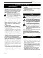
INSTALLER/ CONSUMER
SAFETY INFORMATION
PLEASE READ THIS MANUAL
BEFORE INSTALLING AND
USING APPLIANCE.
WARNING!
IF THE INFORMATION IN THIS
MANUAL IS NOT FOLLOWED
EXACTLY, AN ELECTRICAL
SHOCK OR FIRE MAY RESULT,
CAUSING PROPERTY DAMAGE,
PERSONAL INJURY OR LOSS
OF LIFE.
™
Electric Fireplace
Models:
BREF30/36/42
BREF30NH/36NH/42NH
BREF36R/42R
FOR YOUR SAFETY
SERVICE MUST BE
PERFORMED BY A QUALIFIED
SERVICE AGENCY.
DO NOT STORE OR USE
GASOLINE OR OTHER
FLAMMABLE VAPORS AND
LIQUIDS IN THE VICINITY OF
THIS OR ANY OTHER
APPLIANCE.
C
US
Homeowner's Installation &
Operating Manual
4758
BREF cover
CFM Specialty Home Products
410 Admiral Blvd. • Mississauga, Ontario, Canada L5T 2N6 • 905-670-7777
www.majesticproducts.com • www.vermontcastings.com
INSTALLER: DO NOT DISCARD THIS MANUAL - LEAVE FOR HOMEOWNER
10004758 11/05 Rev. 5
BREF Electric Fireplace
Table of Contents
Please read the Installation & Operating Instructions before using this appliance.
Thank you, and Congratulations on your purchase of a
CFM Specialty Home Products Electric Fireplace.
IMPORTANT: Read all instructions and warnings carefully before starting installation. Failure to follow these
instructions may result in possible electric shock, fire hazard, and/or injury, and will void the warranty.
Installation Instructions
General Information ............................................................................................................ 3
Wiring .................................................................................................................................. 3
Electrical Connection .......................................................................................................... 3
Fireplace Dimensions .......................................................................................................... 4
Electrical Specifications ...................................................................................................... 4
Mantels ................................................................................................................................ 5
Framing ............................................................................................................................... 5
Finishing .............................................................................................................................. 6
Locating your Electric Fireplace .......................................................................................... 6
Clearance to Combustibles ................................................................................................. 6
Hearth ................................................................................................................................. 6
Cabinet Installations ............................................................................................................ 6
Main Power Wall Switch Wiring........................................................................................... 6
120 Volt Wall Switch Wiring Installation .............................................................................. 6
240 Volt Wall Switch Wiring Installation .............................................................................. 7
120/240 Volt Wall-Mounted Thermostat Wiring .................................................................. 7
Installation Cautions ............................................................................................................ 7
120 Volt Unit Installation ...................................................................................................... 8
120 Volt (NH) Unit Installation ............................................................................................. 8
240 Volt Unit Installation ...................................................................................................... 8
Resetting the Temperature Cutout Switch ........................................................................... 8
Screen Kit Installation ....................................................................................................... 9
Service Instructions
Maintenance of Motor ......................................................................................................... 9
Installation of BREF36/BREF36R with Ceramic Log Set .................................................... 9
Installation of BREF42/BREF42R with Ceramic Log Set .................................................... 9
Replacing Light Bulbs ....................................................................................................... 10
Cleaning Trim .................................................................................................................... 10
Electrical Wiring Diagram without Integral Remote Control w/Ceramic Log Set ............... 11
Electrical Wiring Diagram with Integral Remote Control w/Ceramic Log Set .................... 12
Electrical Diagram with Heater and Intregral Remote Control .......................................... 13
Electrical Diagram without Heater and Integral Remote Control....................................... 14
Operating Instructions for Units with Ceramic Log Sets
On/Off Switch .................................................................................................................... 15
Heater Control ................................................................................................................... 15
Relearn .............................................................................................................................. 15
On/Off ................................................................................................................................ 15
Operating Instructions for all Other Units
On/Off Switch .................................................................................................................... 16
Heater Control ................................................................................................................... 16
Remote Control ................................................................................................................. 16
Replacement Parts ...................................................................................................................... 17
Accessories ................................................................................................................................ 20
Warranty ....................................................................................................................................... 23
For Units:
(with ceramic log set)
BREF36
FE10R0
BREF36R
FE10R1
BREF42
GE10R0
BREF42R
GE10R1
2
(all other units)
BREF30
BREF30NH
BREF36
BREF36NH
BREF42
BREF42NH
EFHM4H0
EFNM1H0
EFHM4J0
EFNM1J0
EFHM1M0
EFNM1M0
10004758
BREF Electric Fireplace
Installation Instructions
General Information
1. Read all instructions before using this appliance.
2. This appliance is hot when in use. To avoid burns, do
not let bare skin touch hot surfaces. If provided, use
handles when moving this appliance. Keep combustible materials, such as furniture, pillows, bedding,
papers, clothes and curtains at least
3 feet (1 m) from the front of this appliance.
CAUTION: Extreme caution is necessary
when any heater is used by or near children or invalids, and whenever the heater
is left operating and unattended.
3. Do not operate any heater if the appliance malfunctions, or if it has been dropped or damaged in any
manner.
4. Any repairs to this fireplace should be carried out by
a qualified service person.
5. Under no circumstances should this fireplace be
modified. Parts having to be removed for servicing
must be replaced prior to operating this fireplace
again.
6. Do not use outdoors.
7. This heater is not intended for use in bathrooms,
laundry areas and similar indoor locations. Never
locate this appliance where it may fall into a bathtub
or other water container.
8. This appliance, when installed, must be electrically
grounded in accordance with local codes, or, in the
absence of local codes, with the current CSA C22.1
Canadian Electrical Code; for U.S.A. installations,
follow local codes and the National Electrical Code,
ANSI/ NFPA NO. 70.
9. Do not insert or allow foreign objects to enter any
ventilation or exhaust opening, as this may cause an
electric shock or fire, or damage the appliance.
10. To prevent a possible fire, do not block air intake or
exhaust in any manner. Do not use on soft surfaces
(e.g., beds) where openings may become blocked.
11. This appliance has hot and arcing or sparking parts
inside. Do not use it in areas where gasoline, paint or
flammable liquids are used or stored. This fireplace
should not be used as a drying rack for clothing, nor
should Christmas stockings or decorations be hung
in the area of it.
12. Use this appliance only as described in this manual.
Any other use not recommended by the manufacturer may cause fire, electric shock or injury to persons.
13. Do not burn wood or other materials in this fireplace.
14. Do not strike the fireplace glass.
15. Always use a certified electrician for installation.
10004758
16. Disconnect all power coming to fireplace at main
service panel before performing any cleaning or
maintenance.
17. Do not install this fireplace on carpet or vinyl floors,
as discoloration may occur.
18. SAVE THESE INSTRUCTIONS.
Wiring
Ensure the power conversion/switch (if
equipped) is in the proper position for required supply voltage prior to connecting
the unit to power supply.
Do not use this fireplace if any part of it
has been under water. Immediately call a
qualified service technician to inspect the
fireplace and replace any part of the electrical system that has been under water.
A qualified electrician must perform any
electrical wiring of this appliance. This wiring must be done in accordance with local
codes, and/or in Canada, with the current
CSA C22.1 Canadian Electrical code; for
U.S.A. installation, National Electrical Code
ANSI/NFPA No. 70.
NOTES: The unit is shipped from the factory configured for 120 Volt operation.
Ensure the power conversion switch is in the
proper position for the required supply voltage.
All wiring must be completed prior to installing the
unit.
Electrical Connection
1. Loosen the screws securing junction box cover.
2. Remove knockouts in the box cover to use a cable
clamp.
3. Place the unit in position in the opening. Level it with
shims if necessary, and attach the unit to the frame
using the nailing flanges provided.
4. The unit is factory wired for 120 Volt power supply.
If 208/240 Volt operation is required, flip the switch
located on junction box and reconfigure the wiring
as covered on page 7. Wires L1, L2, N, and G are
located inside the junction box.
5. Wire a dedicated, properly fused, 20 Amp rated
circuit for appropriate voltage (120 or 208/240).
6. Place all connectors inside junction box and replace
the cover to ensure connections are tight.
3
BREF Electric Fireplace
Fireplace Dimensions
M
Rough
Opening
Depth
1/2" (13mm)
H
L
5/8" (16mm)
Recessed
Nailing Flange
m
)
G
6m
K Rough Opening Width
5/
8"
(1
O
Rough
Opening
Height
N
M
E
J
B
F
C
3³⁄₄"
(95mm)
2¹¹⁄₃₂"
(60mm)
D
E
7²⁹⁄₃₂"
(192mm)
A
Fig. 1 Fireplace specifications and framing dimensions.
Ref.
BREF30/BREF30NH
BREF36/BREF36NH/BREF36R
A
34”
(864 mm)
40"
B
36”
(914 mm)
36"
C
30”
(762 mm)
D
21”
E
7¹⁄₂”
F
4758
BREF specs
(1016mm)
1/04
BREF42/BREF42NH/BREF42R
45⁵⁷⁄₆₄"
(1166mm)
(914mm)
36"
(914mm)
36"
(914mm)
42"
(1067mm)
(533 mm)
21"
(533mm)
21"
(533mm)
(191 mm)
7¹⁄₂"
(191mm)
7¹⁄₂"
(191mm)
19³⁄₄”
(502 mm)
19³⁄₄"
(502mm)
19³⁄₄"
(502mm)
G
14”
(356 mm)
14"
(356mm)
16"
(406mm)
H
27¹⁄₂”
(698 mm)
27¹⁄₂"
(698mm)
31¹¹⁄₁₆"
(85mm)
Framing Dimensions
J
36¹⁄₂”
(927 mm)
36¹⁄₂"
(927mm)
36¹⁄₂"
(927mm)
K
35”
(889 mm)
41"
(1041mm)
46⁵⁷⁄₆₄"
(1191mm)
L
14”
(356 mm)
14"
(356mm)
16"
(406mm)
M
37¹⁄₂”
(953 mm)
37¹⁄₂"
(953mm)
49"
(1245mm)
N
54”
(1372 mm)
54"
1372mm)
69¹⁄₂"
(1765mm)
O
27”
(686 mm)
27"
(686mm)
35¹⁄₄"
(895mm)
Electrical Specifications
4
Voltage:
120 Volt
120 Volt (NH)
240 Volt
Total Amps:
13 Amps
2 Amps
12.9 Amps
Total Watts:
1550 Watts
240 Watts
3100 Watts
Heater Rating:
1455 Watts
N/A
2855 Watts
10004758
BREF Electric Fireplace
Mantels
The height that a combustible mantel is fitted above the
fireplace is dependent on the depth of the mantel. This
also applies to the distance between the mantel leg (if
fitted) and the fireplace.
For correct mounting height and width, refer to Figure
2a and 2b.
The distances and reference points are not affected by
the fitting of a bay window front trim kit.
Noncombustible mantels and legs may be installed at
any height and width around the appliance.
When using paint or lacquer to finish the mantel, such
paint or lacquer must be heat-resistant to prevent discoloration.
Mantel Clearances
J
Black
Surround
Face
H
G
F
Mantel Leg
CFM164a
CFM164a
Mantel Leg Chart
06/22/01 sta
V
I
Side of Combustion
Chamber
M
N
O
K
L
W
X
Y
Z
Wall
CFM170
Ref.
A
B
C
D
E
F
G
H
I
J
Mantel
CFM170 Ref.
Leg Depth
DV Builder Front
View
14" (356 mm)
K
12" (305 mm)
L
10" (254 mm)
M
8" (203 mm)
N
1¹⁄₂" (38 mm)
O
Mantel Leg from Side
of Comb. Opening
14" (356 mm)
12" (305 mm)
10" (254 mm)
8" (203 mm)
1¹⁄₂" (38 mm)
Fig. 2b Combustible mantel leg minimum installation.
Top of Combustion
Chamber
Ref.
V
W
X
Y
Z
Framing
CFM146b
Mantel Shelf
Mantel from Top
Ref.
Depth
of Comb. Chamber
14" (356 mm)
A
25" (635 mm)
12" (305 mm)
B
23" (584 mm)
10" (254 mm)
C
21"
(533 mm)
CFM146c
8" (203 mm)
D
19" (483 mm)
Electric Mantel
Chart
1¹⁄₂" (38 mm)
E
15" (381 mm)
1/22/04 djt
Fig. 2a Combustible mantel minimum installation.
10004758
1. Choose fireplace location.
2. Place fireplace into position.
3. Frame in the fireplace with a header across the top.
It is important to allow for finished face when setting
the depth of the frame.
Four (4) nailing flanges are supplied with the fireplace
(found on the fireplace hearth). To level the box and
secure it firmly in place, remove the nailing flanges from
the hearth and install at the sides of the fireplace as
shown in Figure 3.
5
BREF Electric Fireplace
Hearth
Nail
side-nailing
flange
A hearth is not mandatory; however, for aesthetic purposes, we recommend use of a noncombustible hearth
that does not obstruct the air openings.
Cold Climate Installation: To conform to
applicable insulation codes, it is mandatory the outer walls be insulated when
installing this unit against a non-insulated
exterior wall or chase.
Cabinet Installations
FP549
Fig. 3 Adjustable drywall strip (nailing flange).
FP549
9/29/97
Finishing
BR/BC
CAUTION: All joints between the finished
wall and the appliance surround (top and
sides) may be sealed only with noncombustible material. Only noncombustible
material can be applied as facing to
the appliance surround (the black painted
face).
When finishing the appliance, never obstruct or
modify the air inlet/outlet grilles in any manner.
NOTE: Finish the wall with the material of your
choice. Refer to Figures 2a and 2b for specific
clearances when installing a combustible mantel or
other combustible projection.
Locating your Electric Fireplace
Your new fireplace may be installed into an existing
masonry or zero-clearance fireplace. It may also be installed using a prefabricated cabinet available from your
dealer, or be built into a wall.
When choosing a location for your new fireplace, ensure that the general instructions are followed. Also, for
best effect, install the fireplace out of direct sunlight.
Clearance to Combustibles
Sides ......................................................... 0" (0 mm)
Floor .......................................................... 0" (0 mm)
Top ........................................................... 0" (0 mm)
6
Cabinets are available from your dealer which allow
fast, convenient installation of your fireplace against
existing walls.
Main Power Wall Switch Wiring
To reduce the risk of fire, electrical shock,
and personal injury, before attempting
maintenance or service, disconnect all
power to the fireplace
at the main service panel.
120 Volt Wall Switch Wiring Installation
A qualified electrician must perform any
electrical wiring of this appliance. For Canadian installations, wiring must be done
in accordance with local codes, and/or
the current CSA C22.1 Canadian Electrical
Code. For U.S.A. installations, wiring must
be done in accordance with the National
Electrical Code ANSI/ NFPA No. 70.
NOTE: For 120 Volt installations, use a
single-pole, single-throw, 20 Amp-rated wall switch.
(NH models do not require the 20 Amp switch. A
regular 15 Amp wall switch may be used.)
Wiring of the wall switch must be completed prior
to installing the unit.
Connect the wall-mounted switch to the fireplace by
running grounded 2-conductor wire (Min. 14 AWG) to
the switch from the junction box on the side of the unit.
1. Locate the voltage selection switch under the logset
on the left front corner of the unit. (Not applicable to
NH models)
2. Ensure the switch is in the 120 Volt position. (Not
applicable to NH models.)
3. Loosen the screws securing the junction box cover,
and remove the cover.
4. Remove knockouts in the box cover to use a cable
clamp.
5. Pull out two (2) wires: black and white.
6. Connect the hot wire (black) from the wall switch to
the L1 (black) wire on the unit, and the other wire
from the wall switch to the L1 (black) wire on the
power supply.
10004758
BREF Electric Fireplace
7. Connect the white wire from the unit to the neutral
(white) wire on the power supply.
8. Connect the ground wire from the wall switch to the
wire grouping from the power supply and the ground
stud in the junction box.
9. Make sure the red wire (L2) in the junction box has a
closed end splice or a wire nut properly applied.
10.Ensure all connections are tight. Insert all wiring
inside the junction box and secure the cover.
240 Volt Wall Switch Wiring Installation
A qualified electrician must perform any
electrical wiring of this appliance. For
Canadian installation, wiring must be done
in accordance with local codes, and/or
the current CSA C22.1 Canadian Electrical
Code. For U.S.A. installation, wiring must
be done in accordance with the National
Electrical Code ANSI/NFPA No. 70.
NOTE: For 240 Volt installations, use a double-pole,
single-throw, 20 Amp, 240V rated wall switch.
Wiring of the wall switch must be completed prior
to installing the unit.
Connect the wall-mounted switch to the fireplace by
running grounded 3-conductor wire (MIN. 14 AWG) to
the switch from the junction box on the side of the unit.
1. Locate the voltage selection switch under the logset
on the left front corner of the unit.
2. Move the switch from the 120 Volt to the 240 Volt
position.
3. Loosen the screws securing the junction box cover,
and remove the cover.
4. Remove knockouts in the box cover to use a cable
clamp.
5. Pull out three (3) wires: black, red, and white.
6. Connect one (1) wire (black) from the wall switch to
the L1 (black) wire on the unit, and the other wire
from the wall switch to the L1 (black) wire on the
power supply.
7. Connect one (1) of the wires from the wall switch to
the L2 (red) wire on the unit, and the other wire from
the wall switch to the L2 (red) wire on the power supply.
8. Connect the white wire from the unit to the neutral
(white) wire on the power supply.
9. Connect the ground wire from the wall switch to the
wire grouping from the power supply and ground
stud in the junction box.
10. Ensure all connections are tight. Insert all wiring
inside the junction box and secure the cover.
10004758
120/240 Volt Wall-Mounted
Thermostat Wiring
Before attempting maintenance or service—to reduce risk of fire, electrical
shock and personal injury—disconnect all
power to the fireplace at the main service
panel.
NOTE: Wiring of the wall thermostat must be completed prior to the installation of the unit.
Use a single pole thermostat rated for 120/240 Volt
operation.
When installing the wall thermostat, make sure to
turn the heater control inside fireplace all the way
clockwise to the highest set point temperature.
Connect the wall-mounted thermostat to the fireplace
by running a grounded 2-conductor wire (min. 14 AWG)
to the thermostat from the junction box on the side of
the unit.
1. Loosen the screws securing the junction box cover
and remove the cover.
2. Remove knockouts in the box cover to use a cable
clamp.
3. Pull out the two (2) brown wires with the closed end
splice at the end.
4. Cut off the closed end splice, separate the two wires,
and strip approximately 5/8" (15mm).
5. Connect one (1) wire from the thermostat to one (1)
of the brown wires; connect the other wire from the
thermostat to the other brown wire.
6. Connect the ground wire from the wall thermostat to
the power supply wire group and the ground stud in
the junction box.
7. Ensure all connections are tight. Insert all wiring into
the junction box and secure the cover.
Installation Cautions
Make sure the power is turned OFF before
proceeding.
If repairing or replacing any electrical component or wiring, the original wire routing,
color coding and securing locations must
be followed.
Any electrical repairs or rewiring of this
unit should be carried out by a licensed
electrician in accordance with national and
local codes.
7
BREF Electric Fireplace
120 Volt Unit Installation
1. Locate the switch under the logset on the left front
corner of the unit.
2. Check the voltage selection switch position to ensure
it is in the 120 Volt position.
3. Loosen the screws securing the junction box cover
and remove the cover.
4. Remove knockouts in the box cover to use the cable
clamp.
5. Pull out two (2) wires: black and white.
6. Connect the black wire from the unit to the L1 (black)
from the power supply. Connect the white wire from
the unit to the neutral (white) from the power supply.
NOTE: Wiring must be connected to a 20 Amp
dedicated circuit breaker or fuse in the electrical
panel of the dwelling.
7. Connect the ground wire from the power supply to
ground stud in the junction box.
8. Make sure the red wire (L2) in the junction box has a
closed end splice or a wire nut properly applied.
9. When the unit has been configured for the appropriate power supply voltage, ensure all connections
are tight. Insert all wiring inside the junction box and
secure the cover.
10. Turn the power to the unit on at the breaker/fuse
panel. Place the unit into operation and check to
make sure the whole system is operating properly.
120 Volt (NH) Unit Installation
1. Loosen the screws securing the junction box cover
and remove the cover.
2. Remove knockouts in the box cover to use the cable
clamp.
3. Pull out two (2) wires: black and white.
4. Connect the black wire from the unit to the L1 (black)
from the power supply. Connect the white wire form
the unit to the neutral (white) form the power supply.
5. Connect the ground wire from the power supply to
the ground stud in the junction box.
6. Ensure all connections are tight. Insert all wiring
inside the junction box and secure the cover.
7. Turn the power to the unit on at the breaker/fuse
panel. Place the unit into operation and check to
make sure the system is operating properly.
240 Volt Unit Installation
1. Locate the voltage selection switch under the logset
on the left front corner of the unit.
2. Check the switch position to ensure it is in the
240 Volt position.
3. Loosen the screws securing the junction box cover
and remove the cover.
4. Remove knockouts in the box cover to use the cable
clamp.
8
5. Pull out three (3) wires: black, red, and white.
6. The unit is shipped from factory with a closed end
splice on the red wire. Cut off this splice and strip
approximately 5/8" (15mm) wire sheathing.
7. Connect the black wire from the unit to the L1
(black) from the power supply. Connect the red wire
from the unit to the L2 (red) from the power supply.
Connect the white wire from the unit to the neutral
(white) from the power supply.
NOTE: Wiring must be connected to a 20 Amp
dedicated circuit breaker or fuse in the electrical
panel of the dwelling.
8. Connect the ground wire from the power supply to
ground stud in the junction box.
9. When the unit has been configured for the appropriate power supply voltage, ensure all connections
are tight. Insert all wiring inside the junction box and
secure the cover.
10. Turn the power to the unit on at the breaker/fuse
panel. Place the unit into operation and check to
make sure the whole system is operating properly.
Resetting the
Temperature Cutout Switch
To reduce the risk of fire, electrical shock,
and personal injury, before attempting
maintenance or service, disconnect all
power to the fireplace at the main service
panel.
NOTE:The heater on this fireplace is protected with
a safety limit device to prevent overheating. Should
the heater overheat, an automatic cutout turns the
heater OFF; it will not come back ON without being
manually reset.
The safety limit device is located in a cutout at the right
front top corner by the cover fan/ heater. To reset the
switch, insert a small flat screwdriver into this cutout
and push the reset button on the safety limit device.
Safety Limit Device
Cover Fan/
Heater
Small Flat Screwdriver
FP1452
Fig. 4 Reset the switch with a small flat screwdriver.
FP1452
Safety limit switch
2/25/04 djt
10004758
BREF Electric Fireplace
Screen Kit Installation
1. Remove the plastic bag from each screen.
2. Remove the four (4) metal clips, two (2) for each
side of the fireplace opening.
3. Slide screen panels against sides of the fireplace
opening.
4. Align each metal clip with the hole it was removed
from, while at the same time, hooking the clip
through the last wire of the screen. Snap clips into
place. (Fig. 5)
5. Pull screens back and forth to ensure they work
freely.
(Clip)
FP1041
Fig. 5 Clip installation.
Service Instructions
To reduce the risk of fire, electrical shock
or personal injury, disconnect all power
coming to the fireplace at the main service
panel before attempting any maintenance
or cleaning.
B114
Fp1041
screen install
3/30/00 djt
B111
Maintenance of Motor
The motors used on the fan and the drum assemblies
are pre-lubricated for extended bearing life, and require
no further lubrication. However, periodic cleaning/vacuuming of the fan/ heater is recommended.
Installation of BREF36/BREF36R
with Ceramic Log Set
1. Turn OFF power to the unit at the main service
panel.
2. Open glass (if applicable); open the steel curtain.
3. Remove logs from packaging.
NOTE: The ember lava rock is shipped in place;
no adjustment is necessary.
4. Fit the right log (B111) onto the plate log support.
Ensure the bottom holes of B111 are located on the
two pins of the support.
5. Place the center log (B112) on the ember lava rock.
Use the notches under the center portion of B112 to
locate it properly.
6. Place the bottom left log (B113) into position by resting the hole under the center of B113 over the knob
on center top of B112. The other end of B113 rests
against the back wall of the plate log support.
7. Fit the top left log (B114) onto the plate log support.
Ensure the bottom holes of B114 are located on
the two (2) pins of the support; rest the other end of
B114 on the top back of B113.
10004758
B113
B112
LG241
Fig. 6 BREF/BREF36R ceramic log set placement.
Installation of BREF42/BREF42R
with Ceramic Log Set
1. Turn OFF power to the unit at the main service
panel.
LG241
2. Open glass (if applicable);
open the steel curtain.
DEF36 logs
3. Remove logs from packaging.
NOTE: The ember lava
rock is shipped in place;
6/02
no adjustment is necessary.
4. Place the front center log (G3) on the ember lava
rock. Use the notches under the center front of the
log to properly locate the log.
5. Fit the right rear log (G1) on the place support. Ensure the bottom holes of G1 are located on the two
(2) pins of the support; rest the other end of G1 on
the top back of G3.
6. Fit the left rear log (G2) on the place support. Ensure
the bottom holes of G2 are located on the two (2)
pins of the support.
7. Place the front left log (G4) in position by resting the
front left back log on the top right log rear left (G2).
The front of this log will rest against the back wall of
the log support plate.
9
BREF Electric Fireplace
8. Place the right front log (G5) in position on the
ember lava rock. Use the notches under the log front
right to have a proper location.
G2
G1
G4
G3
Cleaning Trim
Clean the trim using a soft cloth you have slightly dampened with lemon oil; then buff with a clean soft cloth.
NOTE: You can obtain lemon oil at super-markets
and hardware stores. Do not use commercially
made brass polish or household cleaners, as these
products will damage the trim.
G5
LG324
Fig. 7 BREF42/BREF42R ceramic log placement.
To reduce the risk of fire, electrical shock
or personal injury, disconnect all power
coming to the fireplace at the main service
panel before attempting any maintenance
or cleaning.
LG324
BREF42 logs
This fireplace uses four 1/04
(4) clear, 120 Volt, 60 Watt,
Replacing Light Bulbs
E-12 socket base (small base, chandelier candle-type)
light bulbs. These lights are located under the ember
bed of the unit.
Do not exceed 60 Watts per bulb. Use of
higher-rated bulbs may result in fire, causing property damage, personal injury, or
loss of life.
NOTE: For the sake of convenience, you may wish
to consider replacing all the light bulbs if one of
them burns out.
1. Turn OFF the power to the unit at the main service
panel.
2. If the fireplace has been operating, allow it to cool.
3. Open glass (if applicable); open steel curtain.
4. Remove the log. Remove the two (2) screws, one
on each side of the ember bed/plate support log set
down. Remove the ember bed/plate support log set.
5. Examine the bulbs to determine which one(s) need
to be replaced (if you are not going to replace all).
7. Install new light bulb(s) by screwing in while holding
the socket.
8. Reinstall the ember bed, log set, glass door, and
steel curtain.
10
10004758
BREF Electric Fireplace
Electrical Wiring Diagram without Integral Remote Control
For Units with Ceramic Log Sets (Refer to Figures 6 & 7)
G
1 WHITE
REAR
1
FRONT
9 RED
2 WHITE
14 BLACK
11 RED
22 WHITE
14 BLACK
4
FAN/HEATER
MOTOR
4 BLACK
T'S
3 BLACK
L1
13
2
13 BLACK
10 BLACK
5
2
5 RED
4
12 BROWN
15
5
3
3
6
12 BROWN
COIL
20 WHITE
6
1b
2
1
2a
1a
18 WHITE
19 WHITE
2b
17 WHITE
9
FLAME
MOTOR
8 BLACK
8
13
7 BLACK
L2
BLACK
16 WHITE
N
12
21 WHITE
7
WHITE
BLACK
6 BLACK
15 WHITE
WHITE
11
10
Component Identification
1.
2.
3.
4.
5.
6.
7.
FP1449
Heater Element
Limit Control, 175/20 DIF
Relay Switch, 120V 50/60Hz
FP1449
Fan/Heater Motor
BREF wiring
Thermostat
Switch, Rocker
Switch
8.
9.
10.
11.
12.
13.
14.
15.
Flame Motor
Light Bulb
Light Socket w/Wiring Assembly
Cable Tie, Nylon 6" - 1¹⁄₂" Black
Bushing Snap, Split 1"
Closed End Splice, 2/18 Ga.Wire
CFM Wire
Sensor, 230°F, Manual Reset
Fig. 8 Wiring Diagram for units with ceramic log set. (Refer to Figure 6 & 7)
10004758
11
BREF Electric Fireplace
Electrical Wiring Diagram with Integral Remote Control
For Units with Ceramic Log Sets (Refer to Figures 6 & 7)
G
1 WHITE
REAR
1
FRONT
11 RED
2 WHITE
16 BLACK
22 WHITE
13 RED
16 BLACK
4
4 BLACK
FAN/HEATER
MOTOR
12 BLACK
L1
5
2
15 BLACK
T'S
1
15
3
2
6 RED
14 BROWN
4
3
6
5
14 BROWN
12
COIL
21 WHITE
24 WHITE
6
2
1
2a
1a
19 WHITE
7
5 BLACK
1b
4 BLACK
13
2b
13
N
9 BLACK
8
9
8 BLACK
3 BLACK
20 WHITE
L2
FLAME
MOTOR
25 RED
10 BLACK
23 WHITE
IN
N
OUT
N
IN
L
18 WHITE
BLACK
WHITE
7 BLACK
OUT
L
16
17 WHITE
BLACK
WHITE
11
10
Component Identification
1.
2.
3.
4.
5.
6.
7.
8.
Heater Element
9. Light Bulb
FP1450
Limit Control, 175/20BREF
DIF wiring10.
Light Socket w/Wiring Assembly
diagram
Relay Switch, 120V, w/remote
50/60Hz 11. Cable Tie Nylon 6"-1¹⁄₂" Black
Fan/Heater Motor
12. Bushing Snap, Split 1"
Thermostat
13. Closed End Splice 2/18 Ga.Wire
Switch, Rocker
14. CFM Wire
Switch
15. Sensor, 230°F Manual Reset
Flame Motor
16. Receiver
FP1450
Fig. 9 Wiring Diagram for units with ceramic log set. (Refer to Figures 6 & 7) BREF36R/BREF42R
12
10004758
BREF Electric Fireplace
Electrical Wiring Diagram with Heater and Integral Remote Control
G
1 WHITE
REAR
16 BLACK
13 RED
22 WHITE
4
4 BLACK
FAN/HEATER
MOTOR
5
T'S
14 BROWN
12
4 BLACK
2
2
3
4
5
6
3
COIL
25 RED
5 BLACK
7
3
FLAME
MOTOR
9 BLACK
9
8 BLACK
20 WHITE
1a
3 BLACK
10 BLACK
23 WHITE
18 WHITE
WHITE
7 BLACK
BLACK
N
1b
1
RED
L2
2a
15
24 WHITE
19 WHITE
BLACK
13
16 BLACK
1
21 WHITE
2b
2
2 WHITE
15 BLACK
6 RED
14 BROWN
16
12 BLACK
L1
1
FRONT
11 RED
17
BLACK
WHITE
17 WHITE
BLACK
WHITE
10
IN OUT IN OUT
N N L L
1.
2.
3.
4.
5.
6.
7.
8.
Component Identification
Heater Element
9.
Limit Control, 175/20 DIF
10.
Relay Switching,
120V, 50/60Hz
12.
FP1541
Fan/Heater Motor
13.
BREF
Thermostat
14.
heat wiring
Switch, Rocker
15.
1/05
Switch
16.
Flame Motor
17.
Light Bulb
Light Socket w/Wiring Assembly
Bushing Snap, Split 1"
Closed End Splice 2/18 Ga. Wire
CFM Wire Req'd BREF36
Sensor, 230°F Manual Reset
Closed End Splice 3/4" 18GA Wire
Receiver
FP1541
Fig. 10 Wiring diagram for models with heat.
10004758
13
BREF Electric Fireplace
Electrical Wiring Diagram without Heater and Integral Remote Control
G
2
7 WHITE
MOTOR
FLAME
N
8 WHITE
O
1
L1
3
2
3
1 4 BLACK
I
3 BLACK
1 BLACK
6 WHITE
BLACK
WHITE
2 BLACK
BLACK
5 WHITE
WHITE
4
CFM Component Identification
1. Switch
2. Flame Motor
3. Light Bulb
4. Light Socket w/Wiring Assembly
6. CFM Wire req'd
FP1540
Fig. 14 Wiring diagram for models without heat. (BREF30NH/BREF36NH/BREF42NH)
FP1540
BREF
no heat wiring
1/05
14
10004758
BREF Electric Fireplace
Operating Instructions
For units with ceramic log sets. (Figs. 6 & 7)
This set of instructions applies to units with ceramic log
sets. (Figs. 6 & 7) The control compartment is located
inside the fireplace behind the steel curtain near the
left front corner. To access the controls, simply slide the
steel curtain open.
Control Panel
1. ON/OFF Switch
FP1451a
2. Heater Control
3. Learn
4. ON/OFF
Fig. 12 Control panel.
1. ON/OFF Switch
The ON/OFF switch is for
supplying power to light efFP1451a
fects of the fireplace. This
switch
is normally illuminated
control
panel
to indicate there is electrical
power
to thelogs
unit.
units w/ceramic
5/05 Control
2. Heater
The heater control acts to turn the heater ON and OFF,
as well as setting the comfort level in the room.
Turn the knob clockwise form the "OFF" position to
place the heater into operation. The further the knob is
rotated clockwise, the higher the set point temperature.
Turn the knob counterclockwise to lower the set point
temperature. Turn it all the way counterclockwise to turn
the heater function OFF.
10004758
3. Relearn
The BREF36R and BREF42R fireplaces with integral
remote control have pre-programmed, matched-pair
receiver/transmitters already set with randomly selected
house codes. It is highly unlikely that the fireplace code
will ever need to be relearned. If the fireplace needs to
relearn receiver/transmitter house codes, perform the
following steps:
1. Be sure there is power to the fireplace.
2. Be sure there is a good battery in the transmitter
(hand-held remote).
3. Open the battery compartment of the remote.
4. Press and release the small button located in the top
left corner. This will randomly select a new house
code in the remote transmitter.
5. Close the remote transmitter battery compartment.
6. Press either the ON or OFF button on the remote
transmitter, and the Learn button on the fireplace at
the same time. The fireplace is now ready to accept
commands from the remote transmitter.
4. ON/OFF
The ON/OFF button on the fireplace (below the Learn
button) is to turn the fireplace ON and OFF when the
battery in remote transmitter is weak, or to manually
operate the fireplace without the remote transmitter.
NOTE: The device complies with Part 15 of the FCC
Rules. Operation is subject to the following two
condition:
1. This device may not cause harmful interference,
and
2. This device must accept any interference received, including interferences that may cause
undesired operation.
15
BREF Electric Fireplace
Operating Instructions
For all other units.
The control compartment is located inside the fireplace
behind the steel curtain near the left front corner. To access the controls, simply slide the steel curtain open.
2. Heater Control
The heater control acts to turn the heater ON and OFF,
as well as setting the comfort level in the room.
Turn the knob clockwise from the "OFF" position to
place the heater into operation. The further the knob is
rotated clockwise, the higher the set point temperature.
Control Panel
1. ON/OFF Switch
Turn the knob counterclockwise to lower the set point
temperature. Turn it all the way counterclockwise to turn
the heater function OFF.
3. Remote Control
2. Heater Control
FP1451
Fig. 13 Control panel.
1. ON/OFF Switch
The ON/OFF switch is for supplying power to light efFP1451
fects of the fireplace. This switch
is normally illuminated
control
panel
to indicate that there is electrical
power
to the unit.
1/04
16
If the unit is equipped with an on/off remote control, this
feature is to turn the flame effect on and off remotely
while the switch on the control panel is off. If the control
panel switch is on, this bypasses the remote control.
The receiver and transmitter is a matched-pair that
is pre-programmed and must be replaced together, if
necessary.
NOTE: The device complies with Part 15 of the FCC
Rules. Operation is subject to the following two
conditions:
1. This device may not cause harmful interference,
and
2. This device must accept any interference received, including interference that may cause
undesired operation.
10004758
BREF Electric Fireplace
BREF36/BREF36R
BREF42/BREF42R
1d
1a
��
��
��
��
1c
1b
2
��
5
4
3
7
8
10
6
12
15
13
16
14
18
17
CFM Specialty Home Products reserves the right to make changes in design, materials, specifications, prices and discontinue colors and products
at any time, without notice.
BREF36/42, BREF36R/42R Electric Fireplace
for Units with Ceramic Log Sets
10004758
4758
BREF older parts
5/05
17
BREF Electric Fireplace
BREF36/42, BREF36R/42R Electric Fireplace
for Units with Ceramic Log Sets (continued)
Ref.
1.
1a.
1b.
1c.
1d.
1e.
2.
3.
4.
5.
6.
7.
8.
9.
10.
11.
12.
13.
14.
15.
16.
17.
18.
19.
18
Description
Log Set Complete
Log
Log
Log
Log
Log
Heater Element
Motor, AC, w/Terminals
Rocker Switch (Illuminated)
Thermostat - Heater Control
Fan w/Bracket Assembly
Sensor, 230°F Manual Reset
Knob - Flame Speed, Heater Controls
Light Filter - Ember Bed (Not shown)
Plate Control Assembly
Screen Tinted Plastic (Not shown)
Ember Lava Rock
Flame Generator Assembly
Plate Log Support Assembly
Socket Light Bulb Lower Assembly
Limit Control, 175/20 DIF
Transmitter
Receiver
CFM Wire Req'd (Not shown)
BREF36
10004797
10004470 (B111)
10004471 (B112)
10004472 (B113)
10004473 (B114)
-10004584
10004262
10001393
10002987
10004695
10004720
10001639
10004518
10006386
10006381
10004517
10003350
10006380
10003568
10001172
--10004851
BREF36R
10004797
10004470 (B111)
10004471 (B112)
10004472 (B113)
10004473 (B114)
-10004584
10004262
10001393
10002987
10004695
10004720
10001639
10004518
10006389
10006381
10004517
10003350
10006380
10003568
10001172
10005140
10005141
10006382
BREF42
10004950
10004945 (G1)
10004946 (G2)
10004947 (G3)
10004948 (G4)
10004949 (G5)
10004584
10004262
10001393
10002987
10004695
10004720
10001639
10004957
10006386
10006391
10004958
10004847
10004853
10003568
10001172
--10004851
BREF42R
10004950
10004945 (G1)
10004946 (G2)
10004947 (G3)
10004948 (G4)
10004949 (G5)
10004584
10004262
10001393
10002987
10004695
10004720
10001639
10004957
10006389
10006391
10004958
10004847
10004853
10003568
10001172
10005140
10005141
10006382
10004758
BREF Electric Fireplace
BREF30/36, BREF30/36NH
2
1
3
4
BREF42/BREF42NH
1
5
8
7
9
6
11
15
13
12
16
14
22
23
21
21
��
17
20
CFM Specialty Home Products reserves the right to make changes in design, materials, specifications, prices and discontinue colors and products
at any time, without notice.
4758
BREF parts
1/05
BREF30/36/42, BREF30NH/36NH/42NH Electric Fireplace
10004758
19
BREF Electric Fireplace
BREF30/36/42, BREF30NH/36NH/42NH Electric Fireplace
(continued)
Ref.
1.
2.
3.
4.
5.
6.
7.
8.
9.
10.
11.
12.
13.
14.
15.
16.
17.
18.
19.
20.
21.
22.
23.
Description
BREF30
Log Set Complete
10006532
Heater Element
10004584
Motor, AC, w/Terminals
10004262
Rocker Switch (Illuminated)
10001393
Thermostat - Heater Control
10002987
Fan w/Bracket Assembly
10004695
Sensor, 230°F Manual Reset
10004720
Knob - Heater Controls
10001639
Plate Control Assembly
10007610
Screen Tinted Plastic (Not Shown)
10007612
Ember Lava Rock
10007461
Flame Generator Assembly
10003350
Support Plate
10007434
Plate Log Support Assembly
10007447
Socket Light Bulb Lower Assembly
10006453
Limit Control, 175/20 DIF
10001172
Transmitter
10008487
Receiver
10008487
CFM Wire Req'd (not shown)
10006382
Screen Assembly
7554299
Screen Rod
3993138
One Piece Screen Pull (2 per Fireplace) 7554239
Cable Clip (4 per Fireplace)
7512135
BREF30NH
10006532
-10004262
10001393
----10007830
10007612
10007461
10003350
10007434
10007447
10006453
---10007639
7554299
3993138
7554239
7512135
BREF36
10006532
10004584
10004262
10001393
10002987
10004695
10004720
10001639
10007443
10007430
10007461
10003350
10007434
10007447
10006453
10001172
10008487
10008487
10006382
7554338
10007433
7554239
7512135
BREF36NH
10006532
-10004262
10001393
----10007608
10007430
10007461
10003350
10007434
10007447
10006453
---10007639
7554338
10007433
7554239
7512135
BREF42
10007664
10004584
10004262
10001393
10002987
10004695
10004720
10001639
10007443
10006391
10007667
10004847
10007673
10007666
10006453
10001172
10008487
10008487
10006382
7554340
10007433
7554239
7512135
BREF42NH
10007664
-10004262
10001393
----10007608
10006391
10007667
10004847
10007673
10007666
10006453
---10007639
7554340
10007433
7554239
7512135
NOTE: Items 17 and 18 (Transmitter and Receiver) must be replaced as a set.
Accessories
The following accessories for these appliances are
available from your local CFM Specialty Home Products
distributor.
NOTE: Each accessory comes with a separate installation instruction for mounting to the particular
appliance. Be sure to read each instruction thoroughly before installing.
Accessory
Thermostat
Power Cord
Refractory Kit
(not available for
units with ceramic
log set)
Bi-fold Glass Doors
20
See your CFM Specialty Home Products distributor or
dealer for other finishing options, such as marble and
mantels that are available in a wide selection of styles.
Description
Wall Thermostat, electric fireplace
Refractory panels give the appliance
a realistic brick look
Glass doors enhance the viewing area
of the fireplace
Model Number
EBWT
10003095
BREF30RK
BREF36RK
BREF42RK
Brushed Brass - 30GDKBB, 36GDKBB, 42GDKBB
Black - 30GDKBK, 36GDKBK, 42GDKBK
Polished Brass - 30GDKDP, 36GDKDP, 42GDKDP
Pewter - 30GDKS, 36GDKS, 42GDKS
10004758
BREF Electric Fireplace
10004758
21
BREF Electric Fireplace
22
10004758
1 YEAR WARRANTY
BREF Electric Fireplace
For MAJESTIC FIREPLACES® Electric Fireplaces
BASIC WARRANTY:
CFM Specialty Home Products (hereinafter referred to
collectively as the "Company") warrants that your new
Majestic Fireplaces® fireplace is free from manufacturing
and material defects for a period of one year from date of
installation, subject to the following conditions and limitations.
1. This electric fireplace must be installed and operated at
all times in accordance with the Installation and Operating
instructions furnished with the product. Any alteration, willful
abuse, accident, or misuse of the product shall nullify this
warranty.
2. This warranty is non-transferrable, and is made to the original
owner, provided that the purchase was made through an
authorized supplier of the Company.
3. This warranty is limited to the repair or replacement of part(s)
found to be defective in material or workmanship, provided that
such part(s) have been subjected to normal conditions of use
and service, after said defect is confirmed by the Company's
inspection.
4. This warranty does not cover the lightbulb(s) included with
the fireplace.
5. The Company may, at its discretion, fully discharge all
obligations with respect to this warranty by refunding the
wholesale price of the defective part(s).
6. Any installation, labour, construction, transportation, or other
related costs/expenses arising from defective part(s), repair,
replacement, or otherwise of same, will not be covered by
this warranty, nor shall the Company assume responsibility
for same. Further, the Company will not be responsible for
any incidental, indirect, or consequential damages, except as
provided by law.
7. All other warranties - expressed or implied - with respect to the
product, its components and accessories, or any obligations/
liabilities on the part of the Company are hereby expressly
excluded.
8. The Company neither assumes, nor authorizes any third party
to assume, on its behalf, any other liabilities with respect to the
sale of this Majestic Fireplaces product.
9. The warranties as outlined within this document do not apply
to non CFM Specialty Home Products accessories used in
conjunction with the installation of this product.
This warranty is void if:
a) The fireplace has been operated in atmospheres
contaminated by chlorine, fluorine or other damaging
chemicals.
b) The fireplace is subjected to prolonged periods of
dampness or condensation.
c) Any alteration, willful abuse, accident, or misuse of the
product.
GLASS DOORS & BRASS PLATED PARTS . . .
Glass doors are not warranted for breakage due to misuse or
accident.
Brass parts should be cleaned with lemon oil only. Brass cleaners
cannot be used. Mortar mix and masonry cleaners may corrode
the brass finish. The Company will not be responsible for, nor will it
warrant any brass parts which are damaged by external chemicals.
IF WARRANTY SERVICE IS NEEDED . . .
1) Contact your supplier. Make sure you have your warranty,
your sales receipt, and the model/serial number of your CFM
Specialty Home Products product.
2) DO NOT ATTEMPT TO DO ANY SERVICE WORK YOURSELF.
10004758
GARANTIE DE BASE:
CFM Specialty Home Products (aux présentes nommée la
"Société") garantit votre nouveau foyer électrique Majestic
Fireplaces® contre tous défauts de fabrication et de matières
premières pour une période d'un an à compter de la date
d'installation, sujet aux conditions et limitations suivantes.
1. Le foyer electrique doit être installé par un entrepreneur de
service autorisé et compétent. Il doit être installé et utilisé
en tout temps selon les instructions d'installation et de
fonctionnement fournies avec le produit. Toute altération,
abus volontaire, accident ou mauvais usage du produit
annulera cette garantie.
2. Cette garantie n'est pas transférable et est offerte à l'acheteur
au détail d'origine, à condition que l'achat soit effectué par
l'entremise d'un détaillant autorisé de la Société.
3. Cette garantie est limitée à la réparation ou au remplacement
de(des) pièce(s) trouvée(s) défectueuse(s) en matières
premières ou main-d'oeuvre, à condition que lesdites
pièces aient été sujettes aux conditions normales d'usage
et de service, après que ledit défaut a été confirmé par une
inspection par la Société.
4. Cette Garantie ne couvre pas les ampoules inclus dans le
foyer électrique.
5. La Société peut, à sa discrétion, se décharger entièrement
de toutes obligations se rapportant à cette garantie en
remboursant le prix de gros de la(des) pièce(s) défectueuse(s).
6. Tous les frais/dépenses d'installation, de main-d'oeuvre, de
construction, de transport ou autres causés par une (des)
pièce(s) défectueuse(s), une réparation, un remplacement ou
autre, ne seront pas couverts sous cette garantie, et la Société
n'assume aucune responsabilité pour ceux-ci. De plus, la
Société ne pourra être tenue responsable pour tous dommages
fortuits ou indirects sauf la ou prévu par la loi.
7. Toutes autres garanties, exprimées ou sous-entendues, en ce
qui a trait au produit, ses composants et accessiores, ou toutes
obligations/responsabilités de la part de la Société sont aux
présentes expressment excluses.
8. La Société n'assume et n'autorise personne à assumer, en son
nom, toutes responsabilités en ce qui a trait à la vente de ce
produit Majestic Fireplaces.
9. Les garanties, telles que décrites dans ce document, ne
s'appliquent accessoires non CFM Specialty Home Products
utilisés conjointement pour l'installation de ce produit.
10. Cette garantie est nulle si:
a) Le foyer a été utilisé dans une atmosphère contaminée
par du chlore, du fluor ou tous autres produits chimiques.
b) Le foyer est assujetti à de longues périodes d'humidité ou
de condensation.
c) Toute altération, abus volontaire, accident ou mauvais
usage du produit annulera cette garantie.
PORTES EN VERRE & PIECES PLAQUEES LAITON . . .
Les portes en verre ne sont pas garanties contre le bris causé par
un mauvais usage ou un accident.
Les pièces en laiton devraient être nettoyées qu'avec de l'essence
de citron. Les nettoyeurs de laiton ne peuvent pas être utilisés. La
Société ne sera pas responsable pour, et ne garantit pas les pièces
en laiton qui sont endommagées par de refoulement.
SI UN SERVICE SOUS GARANTIE EST REQUIS . . .
1) Communiquez avec votre détaillant. Assurez-vous que vous
avez votre garantie, votre reçu de caisse ainsi que le numéro
de modèle/série de votre produit CFM Specialty Home
Products.
2) NE TENTEZ PAS D'EFFECTUER DES REPARATIONS
VOUS-MEME.
23
CFM Specialty Home Products
410 Admiral Blvd. • Mississauga, Ontario, Canada L5T 2N6 • 905-670-7777
www.majesticproducts.com • www.vermontcastings.com