1
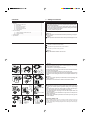
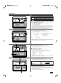
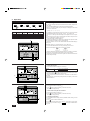
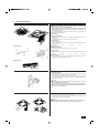
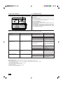
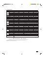
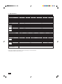
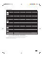
Air-Conditioners
PLH18, 24, 30, 36, 42AK
PL12, 18, 24, 30, 36, 42AK
PCH24, 30, 36, 42EK
PC24, 30, 36,42EK
PKH18, 24, 30, 36FK
PK12, 18, 24, 30, 36FK
FOR USER
OPERATION
MANUAL
For safe and correct use, please read this operation manual thoroughly before operating the air-conditioner unit.
Contents
1. Safety Precautions ....................................................................................
2. Operation ...................................................................................................
2.1. Switching the unit on/off ..............................................................
2.2. Mode select .................................................................................
2.3. Selecting a temperature ..............................................................
2.4. Selecting a fan speed ..................................................................
2.5. Adjusting airflow direction ............................................................
2.6. Using the timer ............................................................................
3. Care and cleaning .....................................................................................
3.1. Cleaning the filters and the indoor unit ........................................
3.2. Care and cleaning .......................................................................
4. Troubleshooting .........................................................................................
5. Specifications ............................................................................................
1. Safety Precautions
2
3
3
3
3
3
4
4
5
5
6
6
7
s Before installing the unit, make sure you read all the “Safety precautions”.
s The “Safety precautions” provide very important points regarding safety.
Make sure you follow them.
s If none of the above apply, turn the main switch off and contact the
dealer from whom you bought the air-conditioner, telling him the model
name and the nature of the problem.
Do not try to fix the unit yourself.
Symbols used in the text
Warning:
Describes precautions that should be observed to prevent danger of injury or
death to the user.
Caution:
Describes precautions that should be observed to prevent damage to the unit.
Symbols used in the illustrations
: Indicates an action that must be avoided.
: Indicates that important instructions must be followed.
: Indicates a part which must be grounded.
Warning:
Carefully read the labels affixed to the main unit.
CENTRALLY
ON/OFF –
CONTROLLE
DRY COOL
D
TIMER OFF
TIMER CLOCK
SWING
AUTO FAN
AUTO AUTO
CHECK SET
TEMP.
HEAT
START STOP FAN
SPEED
STAND BY
DEFROST
˚F
AUTO
RETURN
˚F
NOT AVAILABLE
FILTER
CHECK MODE
TEST RUN
Warning:
• The unit should not be installed by the user. Ask the dealer or an authorized
company to install the unit. If the unit is installed improperly, water leakage,
electric shock or fire may result.
• Do not stand on, or place any items on the unit.
• Do not splash water over the unit and do not touch the unit with wet hands.
An electric shock may result.
• Do not spray combustible gas close to the unit. Fire may result.
• Do not place a gas heater or any other open-flame appliance where it will be
exposed to the air discharged from the unit. Incomplete combustion may
result.
Caution:
• Do not use any sharp object to push the buttons, as this may damage the
remote controller.
• Never block or cover the indoor or outdoor unit’s intakes or outlets.
Warning:
• Do not remove the front panel or the fan guard from the outdoor unit when it
is running. You could be injured if you touch rotating, hot or high-voltage
parts.
• Never insert fingers, sticks etc. into the intakes or outlets, otherwise injury
may result, since the fan inside the unit rotates at high speed.
• If you detect odd smells, stop using the unit, turn off the power switch and
consult your dealer.
• This air conditioner is NOT intended for use by children or infirm persons
without supervisions.
• Young children should be supervised to ensure that they do not play with
the air conditioner.
Disposing of the unit
When you need to dispose of the unit, consult your dealer. If pipes are removed
incorrectly, refrigerant (fluorocarbon gas) may blow out and come into contact with
your skin, causing injury. Releasing refrigerant into the atmosphere also damages
the environment.
2
2. Operation
Operating range
A
ON/OFF –
CENTRALLY CONTROLLED
SWING
˚F
DRY COOL TIMER OFF TIMER CLOCK AUTO AUTO
FAN
AUTO FAN CHECK SET TEMP.
START STOP SPEED
HEAT
STAND BY
DEFROST
˚F
MODE
TIMER ON/OFF CLOCK/TIMER
CHECK MODE
TEST RUN
FAN SPEED AIR DISCHARGE
AIR SWEEP
SET TEMP.
1
FILTER
AUTO
RETURN
NOT AVAILABLE
TIMER SET
Indoor air intake temperature Outdoor air intake temperature
Maximum
95 °F DB, 71 °F WB
115 °F DB
Cooling
Minimum
67 °F DB, 57 °F WB
0 °F DB*
Maximum
80 °F DB, 67 °F WB
75 °F DB, 65 °F WB
Heating
Minimum
70 °F DB, 60 °F WB
17 °F DB, 15 °F WB
* With wind baffle installed. Without wind baffle, the minumum temperature will be
23 °F DB.
2.1. Switching the unit on/off
FILTER
• The power supply should not be turned off while the air conditioner is in use. This
can cause the unit to break down.
1 Press the ON/OFF button.
CHECK
TEST RUN
A The ON indicator should light up.
REMOTE CONTROLLER
• Even if you press the ON/OFF button immediately after shutting down the operation in progress, the air conditioner will not start for about three minutes. This is to
prevent the internal components from being damaged.
• If the operation stops due to a power failure, the unit will not automatically restart
until the power has been restored. Press the ON/OFF button to restart.
2.2. Mode select
1 If the unit is off, press the ON/OFF button to turn it on.
A The ON indicator should light up.
A
ON/OFF –
B
CENTRALLY CONTROLLED
SWING
˚F
DRY COOL TIMER OFF TIMER CLOCK AUTO AUTO
FAN
AUTO FAN CHECK SET TEMP.
START STOP SPEED
HEAT
STAND BY
DEFROST
˚F
MODE
AUTO
RETURN
B
COOL Cooling mode
CHECK MODE
NOT AVAILABLE
TIMER ON/OFF CLOCK/TIMER
1
FILTER
2 Press the operation mode button C and select the operation mode.
TEST RUN
FAN SPEED AIR DISCHARGE
FILTER
DRY
Drying mode
FAN
Fan mode
(For PL/PC/PK)
C
AIR SWEEP
SET TEMP.
TIMER SET
AUTO Automatic (cooling/heating) mode
(For PLH/PCH/PKH)
HEAT Heating mode
(For PLH/PCH/PKH)
CHECK
TEST RUN
REMOTE CONTROLLER
A
Note:
The heating display and the automatic display does not appear in models that
operate exclusively as cooling only air-conditioner.
2.3. Selecting a temperature
s To decrease the room temperature:
1 Press set temperature button to set the desired temperature.
A The selected temperature is displayed.
• Each time you press the button, the temperature value decreases by 2 °F.
ON/OFF –
CENTRALLY CONTROLLED
SWING
STAND BY
DEFROST
˚F
s To increase the room temperature:
1 Press set temperature button to set the desired temperature.
˚F
DRY COOL TIMER OFF TIMER CLOCK AUTO AUTO
FAN
AUTO FAN CHECK SET TEMP.
START STOP SPEED
HEAT
FILTER
AUTO
RETURN
CHECK MODE
NOT AVAILABLE
A The selected temperature is displayed.
TEST RUN
• Each time you press the button, the temperature value increases by 2 °F.
MODE
TIMER ON/OFF CLOCK/TIMER
FAN SPEED AIR DISCHARGE
FILTER
• Available temperature ranges are as follows:
AIR SWEEP
1
SET TEMP.
TIMER SET
CHECK
TEST RUN
REMOTE CONTROLLER
A
Cooling & Drying:
65 - 87 °F
Heating:
61 - 83 °F
Automatic:
65 - 83 °F
• The display flashes either 47 °F or 97 °F to inform you if the room temperture is
lower or higher than the displayed temperature.
2.4. Selecting a fan speed
1 Press fan speed button to select a desired fan speed.
• Each time you press the button, available options change with the display A on
the remote controller, as shown below.
ON/OFF –
CENTRALLY CONTROLLED
SWING
DRY COOL TIMER OFF TIMER CLOCK AUTO AUTO
FAN
AUTO FAN CHECK SET TEMP.
START STOP SPEED
HEAT
STAND BY
DEFROST
MODE
˚F
AUTO
RETURN
NOT AVAILABLE
TIMER ON/OFF CLOCK/TIMER
TIMER SET
Available
Option (Fan Speed Switch)
TEST RUN
FAN SPEED AIR DISCHARGE
FILTER
CHECK
TEST RUN
REMOTE CONTROLLER
1
FAN
SPEED
FAN
SPEED
FILTER
CHECK MODE
AIR SWEEP
SET TEMP.
Display
˚F
Low
-
High
The display and the fan speed of the unit will differ in the following situations:
• When STAND BY and DEFROST are displayed.
• Just after the heating mode (while waiting to change to another mode).
• When the temperature of the room is higher than the temperature setting of the
unit operating in the heating mode.
• In Dry mode, where the speed is set automatically and cannot be changed. Only
the display on the remote controller changes.
3
2. Operation
A
B
C
D
E
2.5. Adjusting airflow direction
The vertical air vane helps select the vertical direction of the airflow. (Except PC24,
30, 36, 42EK)
1 Press AIR DISCHARGE button to select the vertical airflow direction.
• Each time you press the button, the option changes are displayed on the remote
controller, as shown below.
A (swing) → B → C → D → E → A
PL(H)
PK(H)*
PK12FK
PCH
A
Swing
Swing
–
–
B
C
D
E
30°
45°
55°
70°
10°
30°
60°
70°
10°
30°
60°
70°
100% Horizontal 60% Downward 80% Downward 100%Downward
* Except PK12FK
F
AIR SWEEP (PCH24, 30, 36, 42EK and PC24, 30, 36, 42EK only)
2 Press the AIR SWEEP button to turn the jumbo swing louver on or off.
• Remote control display reading when air sweep is in operation.
ON/OFF –
CENTRALLY CONTROLLED
SWING
DRY COOL TIMER OFF TIMER CLOCK AUTO AUTO
FAN
AUTO FAN CHECK SET TEMP.
START STOP SPEED
HEAT
STAND BY
DEFROST
˚F
MODE
˚F
AUTO
RETURN
NOT AVAILABLE
TIMER ON/OFF CLOCK/TIMER
FILTER
CHECK MODE
TEST RUN
FAN SPEED AIR DISCHARGE
AIR SWEEP
SET TEMP.
• In cooling/drying mode with the fan speed set to LOW, every press on the button
will change the direction in the order of A, B, D, A. (C can not be set)
• If D or E is set, the angle will automatically revert to B after one hour of operation.
(Do not use D and E too often in cooling/drying mode with the fan speed set to
LOW, or condensation or dripping can occur.)
F “AUTO RETURN” should be displayed.
• When the angle setting is C in cooling mode, switching the fan speed from HIGH
to LOW will cause the angle to revert to B automatically.
• The airflow direction can not be set with UP/DOWN while the SWING setting is
being used.
• The arrow indicators are alternately displayed when the air sweep is in operation,
however they are not displayed when the air sweep is not in operation.
• The airflow vane of the PCH series and the guide vane of the PKH and PK series
can be changed manually.
FILTER
CHECK
TIMER SET
TEST RUN
REMOTE CONTROLLER
1 2
2.6. Using the timer
BA
1) Set the current time
1 Press clock/timer button to display the “CLOCK” B.
Remote
controller display A
ON/OFF –
CENTRALLY CONTROLLED
SWING
DRY COOL TIMER OFF TIMER CLOCK AUTO AUTO
FAN
AUTO FAN CHECK SET TEMP.
START STOP SPEED
HEAT
STAND BY
DEFROST
˚F
MODE
˚F
CHECK MODE
NOT AVAILABLE
TEST RUN
FAN SPEED AIR DISCHARGE
1
AIR SWEEP
SET TEMP.
↑
AUTO
→ START
→ AUTO
→ No Display
STOP
FILTER
AUTO
RETURN
TIMER ON/OFF CLOCK/TIMER
CLOCK
TIMER SET
FILTER
CHECK
TEST RUN
2
2 Each time you press TIMER SET button, the time increases in increments of one minute.
TIMER SET
Each time you press
button, the time decreases in increments of one minute.
• Press and hold the button to rapidly change the time.
• The time changes in increments of one minute → ten minutes → in units of hour; in
this order.
• Approximately ten seconds after pressing the button, the display on the remote
controller will turn off.
REMOTE CONTROLLER
2) Set the time to start the unit as follows
A BC
1 Press clock/timer button to display B
2 Press
SWING
DRY COOL TIMER OFF TIMER CLOCK AUTO AUTO
FAN
AUTO FAN CHECK SET TEMP.
START STOP SPEED
HEAT
STAND BY
DEFROST
˚F
˚F
AUTO
RETURN
NOT AVAILABLE
.
button to set the time that you want the unit to start.
The start time is displayed at A.
ON/OFF –
CENTRALLY CONTROLLED
TIMER SET
AUTO
START
3) Set the time to stop the unit as follows
FILTER
1 Press clock/timer button to display C
CHECK MODE
TEST RUN
2 Press
TIMER SET
AUTO
STOP
.
button to set the time that you want the unit to stop.
The stop time is displayed at A.
MODE
TIMER ON/OFF CLOCK/TIMER
1
FAN SPEED AIR DISCHARGE
AIR SWEEP
SET TEMP.
REMOTE CONTROLLER
TIMER SET
FILTER
4) Changing the set times
CHECK
TEST RUN
2
1 Press clock/timer button to display the time (CURRENT, START, STOP) you want
to change.
2 Press
button to set the desired time.
TIMER SET
• When change is made to either one of a pair, e.g., AUTO START or AUTO STOP,
set the time you need not to change to
. This display is available following 23:50.
4
3. Care and cleaning
■ PLH/PL Series
B
A
C
Caution:
• Always turn off the power, first on the remote controller and then the main
switch, before cleaning or servicing the unit.
• When installing or removing the filter or the intake grille, do not stand on an
unsteady surface. You may fall and injure yourself. Be also careful not to let
dust fall into your eyes.
Dirty or clogged filters block the airflow and reduce efficiency. Very dirty filters can
damage the air-conditioner itself.
■ PLH/PL Series
Intake grille removal
• Pull the knob on the intake grille in the direction indicated by the arrow and it
should open.
• Unhook the hinges to remove the intake grille from the grille.
Filter removal
D
• Open the intake grille.
• Release the knob on the center edge of the intake grille and pull the filter forward
to remove the filter.
A Knob
■ PCH/PC Series
B Grille
C Intake grille
D Filter
■ PCH/PC Series
Intake grille removal
• Pull handle on intake grille in direction of arrow to open grille.
Filter removal
• Hold filter handle and release from catch on grille, and pull out the small filter as
well.
A Handle
B Intake grille
C Handle
D Filter
E Small filter
■ PKH/PK Series
• Hold the filter lug (located at the bottom of the intake grill) and pull it out downward.
• To install the filters, push the filter lug upward.
A Filter
B Lug
■ PKH/PK Series
B
A
3.1. Cleaning the filters and the indoor unit
Cleaning the filters
• Clean the filters using a vacuum cleaner. If you do not have a vacuum cleaner, tap
the filters against a solid object to knock off dirt and dust.
• If the filters are especially dirty, wash them in lukewarm water. Take care to rinse
off any detergent thoroughly and allow the filters to dry completely before putting
them back into the unit.
Caution:
• Do not dry the filters in direct sunlight or by using a heat source, such as an
electric heater: this may warp them.
• Do not wash the filters in hot water (above 120°F), as this may warp them.
• Make sure that the air filters are always installed. Operating the unit without
air filters can cause malfunction.
Cleaning the indoor unit
• Wipe the outside of the unit with a clean, dry, soft cloth.
• Clean off any oil stains or finger marks using a neutral household detergent (such
as dishwashing liquid or laundry detergent).
Caution:
Never use gasoline, benzene, thinner, scouring powder or any type of nonneutral detergent, as these substances may damage the unit’s case.
ON/OFF –
CENTRALLY CONTROLLED
SWING
DRY COOL TIMER OFF TIMER CLOCK AUTO AUTO
FAN
AUTO FAN CHECK SET TEMP.
START STOP SPEED
HEAT
STAND BY
˚F
˚F
AUTO
RETURN
NOT AVAILABLE
FILTER
CHECK MODE
TEST RUN
DEFROST
5
3. Care and cleaning
4. Troubleshooting
3.2. Care and cleaning
A
Clean the filter
When the A “FILTER” indicator blinks on the remote controller to alert you to the
necessity of cleaning of the filter.
∗ As a guideline for typical office environment, the long-life filter must be cleaned
every 2,500 (PL(H))/100 (PC(H), PK(H)) operating hours.
ON/OFF –
CENTRALLY CONTROLLED
SWING
DRY COOL TIMER OFF TIMER CLOCK AUTO AUTO
FAN
AUTO FAN CHECK SET TEMP.
START STOP SPEED
HEAT
STAND BY
DEFROST
MODE
˚F
˚F
AUTO
RETURN
NOT AVAILABLE
TIMER ON/OFF CLOCK/TIMER
FILTER
Reset the FILTER indicator
CHECK MODE
TEST RUN
FAN SPEED AIR DISCHARGE
FILTER
1
AIR SWEEP
SET TEMP.
TIMER SET
CHECK
TEST RUN
REMOTE CONTROLLER
1 Press the FILTER button twice after cleaning.
s When you press the FILTER button twice, the “FILTER” indicator A will be
turned off and reset.
s The FILTER indicator provides you with a guideline for the necessity of
filter cleaning based on total operating hours in typical indoor air conditions. Depending on different operating environments, more or less frequent cleaning may be necessary.
4. Troubleshooting
Before you call out a repair man, check the following table to see whether there is a simple solution to your problem.
Problem
Unit will not start.
Display reading
Cause
Pilot lamp does not turn on even when the Main power switch is turned off.
POWER ON/OFF button is pressed.
Main power fuse has blown.
Solution
Turn main power on. Then press the
POWER ON/OFF button to turn the unit
on.
Replace the fuse.
Outdoor unit’s ground fault breaker is open. Reset the ground fault breaker.
A power cut has occurred (see NOTE be- Wait until power is restored, then press
the POWER ON/OFF button to turn the
low).
unit on.
Unit discharges air well, but fails to cool Remote controller shows that the unit is Improper temperature setting - e.g. you
operating.
have selected COOL mode, but the desired
or heat the room well.
temperature setting is higher than the current room temperature.
Filters are clogged.
Check the set temperature on the remote
controller and the actual intake air temperature. Use the COOLER and
WARMER buttons to set the temperature
as described in “Selecting a temperature”
on page 3.
Clean the filter and resume operation.
See “Cleaning the filters and the indoor
unit” on page 5.
Outdoor unit’s intake or outlet is obstructed. Remove the obstruction.
A door or window has been left open.
Shut door or window.
Unit does not start immediately.
Remote controller shows that the unit is Unit is waiting three minutes before restart- Wait until the unit restarts automatically.
operating.
The compressor may hesitate resuming
ing.
because a three-minute resume prevention circuit is incorporated in the outdoor
unit for protection of the compressor.
Unit stops soon after starting.
Remote controller check display reads Indoor or outdoor unit’s intake or outlet is Remove obstruction and restart the unit.
“CHECK P6” or “CHECK P8”.
obstructed.
Filters are clogged.
Remove the obstruction. Clean the filter
and resume operation.
NOTE: After a power cut, the unit will not restart automatically. You will have to restart it by pressing the POWER - ON/OFF button on the remote controller.
Wired remote controllers
In any of the following cases, turn off the main power switch and contact your local dealer for service:
• “CHECK” followed by “P1”, “P2”, “P3”, “P4”, “P5”, “P7” or “CENTRALLY CONTROLLED” is displayed on the control panel.
• The switches do not work properly.
• The circuit breaker trips frequently (or the fuse blows frequently).
• Water has accidentally been splashed into the unit.
• Water leaks from the unit.
• Something is accidentally dropped into the air-conditioner.
• An unusual noise is heard during operation.
6
5. Specifications
Item
Models
Cooling
*1 BTU/h
Capacity
Heating *1,*3 BTU/h
Heating *2,*3 BTU/h
Cooling
*1 kW
Power
Heating
*1,*3
kW
consumption
Heating
*2,*3 kW
SEER
HSPF
INDOOR UNIT MODELS
External finish
Power supply
V, Phase, Hz
Max. fuse size (time delay)
A
Min. ampacity
A
Fan motor
F. L. A.
Auxiliary heater
A (kW)
Airflow
Dry
CFM
Lo-Hi
Wet
CFM
W
in
Dimensions D
in
H
in
W
in
Dimensions
D
in
(GRILLE)
H
in
Weight
lbs
Weight (GRILLE)
lbs
OUTDOOR UNIT MODELS
External finish
Power supply
V, Phase, Hz
Max. fuse size (time delay)
A
Min. ampacity
A
Fan motor
F. L. A.
Models
Compressor
R. L. A.
L. R. A.
Crankcase heater
A (W)
Refrigerant control
Defrost method
W
in
Dimensions D
in
H
in
Weight
lbs
REMOTE CONTROLLER
Control voltage
(by built-in transformer)
NOTES:
PLH18AK
18,000
19,000 [24,500/25,500]
11,000 [16,500/17,500]
1.75
1.59 [3.19/3.49]
1.32 [2.92/3.22]
10.5
7.2
PLH18AK
PLH24AK
24,000
26,000 [31,500/32,500]
16,500 [22,000/23,000]
2.57
2.51 [4.11/4.41]
2.15 [3.75/4.05]
10.3
7.0
PLH24AK
PLH30AK
30,000
33,000 [39,500/41,200]
18,500 [25,000/26,700]
3.17
3.04 [4.94/5.44]
2.55 [4.45/4.95]
10.4
6.9
PLH30AK
Munsell 0.7Y 8.59/0.97
208/230, 1, 60
PLH36AK
35,400
38,000 [45,900/47,600]
23,000 [30,900/32,600]
3.63
3.45 [5.75/6.25]
2.93 [5.23/5.73]
10.0
7.1
PLH36AK
20
15
25
17
0.7
1.2
7.7/8.3 [1.6/1.9]
530-710
490-670
PLH42AK
42,000
44,300 [52,200/53,900]
26,800 [34,700/36,400]
3.98
3.82 [6.12/6.62]
3.24 [5.54/6.04]
10.7
7.0
PLH42AK
1.4
11.1/12.2 [2.3/2.8]
780-1060
740-1020
9.1/10.4 [1.9/2.4]
710-990
670-950
33-1/16
33-1/16
10-3/16
11-3/4
37-3/8
37-3/8
1-3/16
57
71
PUH18EK
PUH24EK
20
16
0.75
RH247NAB
12.0
37
0.11/0.17 (23/28)
PUH36EK
30
20
0.65+0.65
NH33NBD
11.5
54
34-1/4
11-5/8
33-1/2
131
75
11
PUH30EK
Munsell 5Y 7/1
208/230, 1, 60
202
22
0.75+0.75
NH41NAD
NH47NAD
14.0
17.5
73
87
0.16/0.17 (33/39)
Capillary tube
Reverse cycle
38-3/16
13-9/16
49-9/16
245
246
With grille
PUH42EK7
40
28
0.8+0.8
ZR42K3-PFV
20.4
109
246
Indoor unit-remote controller DC12V, Indoor unit- outdoor unit DC12V
*1 Rating conditions (cooling) – indoor: 80°F DB. 67°F WB
outdoor: 95°F DB. 75°F WB
(heating) – indoor: 70°F DB. 60°F WB
outdoor: 47°F DB. 43°F WB
*2 Rating conditions (heating) – indoor: 70°F DB. 60°F WB
outdoor: 17°F DB. 15°F WB
*3 Heating capacity and power consumption in [ ] include auxiliary electric heater operation at 208/230V.
Units should be installed by licensed electric contractor accordingly to local code requirement.
* Specifications subject to change without notice.
7
5. Specifications
Item
Models
Cooling capacity
*1 BTU/h
Power consumption
*1 kW
SEER
INDOOR UNIT MODELS
External finish
External finish (GRILLE)
Power supply
V, Phase, Hz
Max. fuse size (time delay)
A
Min. ampacity
A
Fan motor
F. L. A.
Airflow
Dry
CFM
Lo-Hi
Wet
CFM
W
in
Dimensions D
in
H
in
W
in
Dimensions
D
in
(GRILLE)
H
in
Weight
lbs
Weight (GRILLE)
lbs
OUTDOOR UNIT MODELS
External finish
Power supply
V, Phase, Hz
Max. fuse size (time delay)
A
Min. ampacity
A
Fan motor
F. L. A.
Model
Compressor
R. L. A.
L. R. A.
Crankcase heater
A (W)
Refrigerant control
W
in
Dimensions D
in
H
in
Weight
lbs
REMOTE CONTROLLER
Control voltage
(by built-in transformer)
NOTES:
PL12AK
12,500
1.26
10.1
PL12AK
PL18AK
18,400
1.85
10.2
PL18AK
PL24AK
PL30AK
PL36AK
PL42AK
24,000
31,000
36,500
42,500
2.65
3.17
3.64
4.08
10.0
10.6
10.5
10.8
PL24AK
PL30AK
PL36AK
PL42AK
Galvanized sheets with gray heat insulation
Munsell 0.7Y 8.59/0.97
115, 1, 60
15
2.0
3.0
1.2
2.6
420-560
530-710
710-990
780-1060
390-530
490-670
670-950
740-1020
33-1/16
33-1/16
10-3/16
11-3/4
37-3/8
37-3/8
1-3/16
49
53
66
71
11
PU12EK
PU18EK
PU24EK
PU30EK
PU36EK
PU42EK7
Munsell 5Y 7/1
208/230, 1, 60
15
20
30
40
11
16
20
22
28
0.65
0.75
0.65+0.65
0.75+0.75
0.8+0.8
RH167NAB
RH247NAB
NH33NBD
NH41NAD
NH47NAD
ZR42K3-PFV
8.9
12.0
11.5
14.0
17.5
20.4
29
37
54
73
87
109
0.11/0.12 (23/28)
0.16/0.17 (33/39)
Capillary tube
34-1/4
38-3/16
11-5/8
13-9/16
25-9/16
33-1/2
49-9/16
105
154
207
220
220
With grille
Indoor unit-remote controller DC12V, Indoor unit- outdoor unit DC12V
*1 Rating conditions (cooling) – indoor: 80°F DB. 67°F WB
outdoor: 95°F DB. 75°F WB
Units should be installed by licensed electric contractor accordingly to local code requirement.
* Specifications subject to change without notice.
8
5. Specifications
Item
Models
Cooling
*1 BTU/h
Capacity
Heating *1,*3 BTU/h
Heating *2,*3 BTU/h
Cooling
*1 kW
Power
Heating
*1,*3
kW
consumption
Heating
*2,*3 kW
SEER
HSPF
INDOOR UNIT MODELS
External finish
Power supply
V, Phase, Hz
Max. fuse size (time delay)
A
Min. ampacity
A
Fan motor
F. L. A.
Auxiliary heater
A (kW)
Airflow
Dry
CFM
Lo-Hi
Wet
CFM
W
in
Dimensions D
in
H
in
Weight
lbs
OUTDOOR UNIT MODELS
External finish
Power supply
V, Phase, Hz
Max. fuse size (time delay)
A
Min. ampacity
A
Fan motor
F. L. A.
Models
Compressor
R. L. A.
L. R. A.
Crankcase heater
A (W)
Refrigerant control
Defrost method
W
in
Dimensions D
in
H
in
Weight
lbs
REMOTE CONTROLLER
Control voltage
(by built-in transformer)
NOTES:
PCH24EK
24,000
27,000 [33,800/35,500]
18,400 [25,200/26,900]
2.46
2.42 [4.42/4.92]
2.1 [4.1/4.6]
10.3
7.1
PCH24EK
PCH30EK
PCH36EK
30,000
35,400
33,000 [39,800/41,500]
38,000 [45,900/47,600]
20,900 [27,700/29,400]
19,600 [27,500/29,200]
3.06
3.53
3.13 [5.13/5.63]
3.4 [5.7/6.2]
2.6 [4.6/5.51]
2.7 [5.0/5.5]
10.0
10.4
7.1
7.4
PCH30EK
PCH36EK
Munsell 2.5Y 8/0.3 & N2
208/230, 1, 60
25
15
20
12
PCH42EK
42,000
45,000 [52,900/54,600]
24,800 [32,700/34,400]
4.37
4.3 [6.6/7.1]
3.2 [5.5/6.0]
10.0
7.3
PCH42EK
17
1.3
10.8/12.0 [2.3/2.8]
990-1270
860-110
62-1/4
0.7
9.8/10.8 [2.0/2.5]
830-920
670-740
50-7/16
26-13/16
10-1/8
97
PUH24EK
20
16
0.65+0.65
NH33NBD
11.5
54
119
PUH30EK
PUH36EK
Munsell 5Y 7/1
208/230, 1, 60
30
20
22
0.75+0.75
NH41NAD
14.0
73
NH47NAD
17.5
87
PUH42EK
40
27
0.8+0.8
NH569NXA
20
105
0.16/0.17 (33/39)
Capillary tube
Reverse cycle
34-1/4
11-5/8
38-3/16
13-9/16
49-9/16
202
245
246
268
With indoor unit
Indoor unit-remote controller DC12V, Indoor unit- outdoor unit DC12V
*1 Rating conditions (cooling) – indoor: 80°F DB. 67°F WB
outdoor: 95°F DB. 75°F WB
(heating) – indoor: 70°F DB. 60°F WB
outdoor: 47°F DB. 43°F WB
*2 Rating conditions (heating) – indoor: 70°F DB. 60°F WB
outdoor: 17°F DB. 15°F WB
*3 Heating capacity and power consumption in [ ] include auxiliary electric heater operation at 208/230V.
Units should be installed by licensed electric contractor accordingly to local code requirement.
* Specifications subject to change without notice.
9
5. Specifications
Item
Models
Cooling capacity
*1 BTU/h
Power consumption
*1 kW
SEER
INDOOR UNIT MODELS
External finish
Power supply
V, Phase, Hz
Max. fuse size (time delay)
A
Min. ampacity
A
Fan motor
F. L. A.
Airflow
Dry
CFM
Lo-Hi
Wet
CFM
W
in
Dimensions D
in
H
in
Weight
lbs
OUTDOOR UNIT MODELS
External finish
Power supply
V, Phase, Hz
Max. fuse size (time delay)
A
Min. ampacity
A
Fan motor
F. L. A.
Model
Compressor
R. L. A.
L. R. A.
Crankcase heater
A (W)
Refrigerant control
W
in
Dimensions D
in
H
in
Weight
lbs
REMOTE CONTROLLER
Control voltage
(by built-in transformer)
NOTES:
PC24EK
24,000
2.43
10.3
PC24EK
PC30EK
PC36EK
31,000
36,500
3.10
3.80
10.4
10.2
PC30EK
PC36EK
Munsell 2.5Y 8/0.3 & N2
115, 1, 60
15
3.0
1.8
850-1050
730-900
50-7/16
26-13/16
2.4
990-1270
860-1100
62-1/4
26-13/16
10-1/8
93
115
PU24EK
PU30EK
PU36EK
PU42EK2
22
0.75+0.75
NH47NAD
17.5
87
40
27
0.8+0.8
NH569NXA
20.0
105
Munsell 5Y 7/1
208/230, 1, 60
30
20
16
20
0.65+0.65
NH33NBD
11.5
54
NH41NAD
14.0
73
0.16/0.17 (33/39)
Capillary tube
34-1/4
11-5/8
38-3/16
13-9/16
49-9/16
207
208
220
With indoor unit
Indoor unit-remote controller DC12V, Indoor unit- outdoor unit DC12V
*1 Rating conditions (cooling) – indoor: 80°F DB. 67°F WB
outdoor: 95°F DB. 75°F WB
Units should be installed by licensed electric contractor accordingly to local code requirement.
* Specifications subject to change without notice.
10
PC42EK
42,500
4.40
10.0
PC42EK
260
5. Specifications
Item
Models
Cooling
*1 BTU/h
Capacity
Heating *1,*3 BTU/h
Heating *2,*3 BTU/h
Cooling
*1 kW
Power
Heating
*1,*3
kW
consumption
Heating
*2,*3 kW
SEER
HSPF
INDOOR UNIT MODELS
External finish
Power supply
V, Phase, Hz
Max. fuse size (time delay)
A
Min. ampacity
A
Fan motor
F. L. A.
Auxiliary heater
A (kW)
Airflow
Dry
CFM
Lo-Hi
Wet
CFM
W
in
Dimensions D
in
H
in
Weight
lbs
OUTDOOR UNIT MODELS
External finish
Power supply
V, Phase, Hz
Max. fuse size (time delay)
A
Min. ampacity
A
Fan motor
F. L. A.
Models
Compressor
R. L. A.
L. R. A.
Crankcase heater
A (W)
Refrigerant control
Defrost method
W
in
Dimensions D
in
H
in
Weight
lbs
REMOTE CONTROLLER
Control voltage
(by built-in transformer)
NOTES:
PKH18FK
18,000
18,600 [24,100/25,100]
10,700 [16,200/17,200]
1.79
1.56 [3.16/3.46]
1.34 [2.94/3.24]
11.1
7.2
PKH18FK
PKH24FK
PKH30FK
24,000
30,000
25,000 [30,500/31,500]
33,000 [39,100/40,500]
14,700 [20,200/21,200]
19,000 [25,100/26,500]
2.36
3.12
2.37 [3.97/4.27]
3.02 [4.82/5.22]
1.92 [3.52/3.82]
2.48 [4.28/4.68]
10.2
10.6
6.8
7.1
PKH24FK
PKH30FK
Munsell 3.4Y 7.7/0.8
208/230, 1, 60
15
12
0.5
7.6/8.4 [1.6/1.9]
710-530
640-480
55-1/8
PKH36FK
34,200
38,000 [44,100/45,500]
19,600 [25,700/27,100]
3.44
3.54 [5.34/5.74]
2.65 [4.45/4.85]
10.5
6.9
PKH36FK
13
0.6
8.7/9.6 [1.8/2.2]
990-780
890-700
66-5/32
9-1/4
13-3/8
57
PUH18EK
66
PUH24EK
PUH30EK
PUH36EK
Munsell 5Y 7/1
208/230, 1, 60
20
16
0.75
RH247NAB
12.0
37
0.11/0.12 (23/28)
30
20
0.65+0.65
NH33NBD
11.5
54
22
0.75+0.75
NH41NAD
14.0
73
0.16/0.17 (33/39)
NH47NAD
17.5
87
Capillary tube
Reverse cycle
34-1/4
11-5/8
33-1/2
131
38-3/16
13-9/16
49-9/16
245
202
246
With indoor unit
Indoor unit-remote controller DC12V, Indoor unit- outdoor unit DC12V
*1 Rating conditions (cooling) – indoor: 80°F DB. 67°F WB
outdoor: 95°F DB. 75°F WB
(heating) – indoor: 70°F DB. 60°F WB
outdoor: 47°F DB. 43°F WB
*2 Rating conditions (heating) – indoor: 70°F DB. 60°F WB
outdoor: 17°F DB. 15°F WB
*3 Heating capacity and power consumption in [ ] include auxiliary electric heater operation at 208/230V.
Units should be installed by licensed electric contractor accordingly to local code requirement.
* Specifications subject to change without notice.
11
5. Specifications
Models
Item
Cooling capacity
*1 BTU/h
Power consumption
*1 kW
SEER
INDOOR UNIT MODELS
External finish
Power supply
V, Phase, Hz
Max. fuse size (time delay)
A
Min. ampacity
A
Fan motor
F. L. A.
Airflow
Dry
CFM
Lo-Hi
Wet
CFM
W
in
Dimensions D
in
H
in
Weight
lbs
OUTDOOR UNIT MODELS
External finish
Power supply
V, Phase, Hz
Max. fuse size (time delay)
A
Min. ampacity
A
Fan motor
F. L. A.
Model
Compressor
R. L. A.
L. R. A.
Crankcase heater
A (W)
Refrigerant control
W
in
Dimensions D
in
H
in
Weight
lbs
REMOTE CONTROLLER
Control voltage
(by built-in transformer)
NOTES:
PK12FK
12,500
1.21
11.5
PK12FK
PK18FK
18,500
1.75
11.3
PK18FK
PK24FK
24,000
2.34
10.6
PK24FK
Munsell 3.4Y 7.7/0.8
115, 1, 60
15
PK30FK
30,000
3.06
10.7
PK30FK
1
0.7
490-350
440-320
49-7/32
7-7/8
11-13/16
37
PU12EK
PK36FK
34,200
3.47
10.2
PK36FK
2
1.0
990-780
890-700
66-5/32
710-530
640-480
55-1/8
9-1/4
13-3/8
53
PU18EK
15
11
0.65
0.75
RH167NAB
RH247NAB
8.9
12.0
29
37
0.11/0.12 (23/28)
62
PU24EK
Munsell 5Y 7/1
208/230, 1, 60
PU30EK
20
16
PU36EK
30
20
0.65+0.65
NH33NBD
11.5
54
NH41NAD
14.0
73
0.16/0.17 (33/39)
22
0.75+0.75
NH47NAD
17.5
87
Capillary tube
34-1/4
11-5/8
25-9/16
105
33-1/2
154
38-3/16
13-9/16
207
With indoor unit
49-9/16
208
220
Indoor unit-remote controller DC12V, Indoor unit- outdoor unit DC12V
*1 Rating conditions (cooling) – indoor: 80°F DB. 67°F WB
outdoor: 95°F DB. 75°F WB
Units should be installed by licensed electric contractor accordingly to local code requirement.
* Specifications subject to change without notice.
HEAD OFFICE: MITSUBISHI DENKI BLDG., 2-2-3, MARUNOUCHI, CHIYODA-KU, TOKYO 100-8310, JAPAN
BG79P948H01
12
Printed in Japan